EP4174548B1 - Dispositif de connexion externe, module oculaire et appareil portatif - Google Patents
Dispositif de connexion externe, module oculaire et appareil portatif Download PDFInfo
- Publication number
- EP4174548B1 EP4174548B1 EP21832388.9A EP21832388A EP4174548B1 EP 4174548 B1 EP4174548 B1 EP 4174548B1 EP 21832388 A EP21832388 A EP 21832388A EP 4174548 B1 EP4174548 B1 EP 4174548B1
- Authority
- EP
- European Patent Office
- Prior art keywords
- extension portion
- eyepiece
- connection device
- section
- external connection
- Prior art date
- Legal status (The legal status is an assumption and is not a legal conclusion. Google has not performed a legal analysis and makes no representation as to the accuracy of the status listed.)
- Active
Links
Images

Classifications
-
- G—PHYSICS
- G02—OPTICS
- G02B—OPTICAL ELEMENTS, SYSTEMS OR APPARATUS
- G02B25/00—Eyepieces; Magnifying glasses
- G02B25/001—Eyepieces
-
- F—MECHANICAL ENGINEERING; LIGHTING; HEATING; WEAPONS; BLASTING
- F41—WEAPONS
- F41G—WEAPON SIGHTS; AIMING
- F41G11/00—Details of sighting or aiming apparatus; Accessories
-
- G—PHYSICS
- G02—OPTICS
- G02B—OPTICAL ELEMENTS, SYSTEMS OR APPARATUS
- G02B7/00—Mountings, adjusting means, or light-tight connections, for optical elements
- G02B7/02—Mountings, adjusting means, or light-tight connections, for optical elements for lenses
- G02B7/021—Mountings, adjusting means, or light-tight connections, for optical elements for lenses for more than one lens
Definitions
- the present disclosure relates to the technical field of hand-held apparatus accessories, in particular to an external connection device, an eyepiece module and a hand-held apparatus.
- observation structures such as lens components, sights, etc.
- these observation structures all include eyepiece modules.
- the eyepiece module needs to be additionally equipped with a functional component such as a night vision component and a focusing component based on an extended external tool.
- the extended external tool can only adapt to a functional structure of one size.
- the eyepiece module is equipped with a functional structure of a different size, the extended external tool needs to be replaced, and the existing extended external tool undoubtedly has poor applicability.
- the present disclosure adopts the following technical solution.
- the present disclosure provides an external connection device for connecting an eyepiece to an external functional component.
- the external connection device disclosed includes a main body part and a locking mechanism, wherein the main body part is a cylindrical structural member, and the inner surface of the main body part is provided with a separation portion arranged in a ring shape, which separates the main body part into a connecting section and a mounting section, and the main body part is connected to the eyepiece via the mounting section; a side wall of the connecting section is provided with a notch region and a deformation gap that is arranged in the circumferential direction of the connecting section, the notch region is in connection with the deformation gap, and is extended to an end of the connecting section away from the mounting section, and the connecting section forms a first hold hoop part and a second hold hoop part on two sides of the notch region respectively; the locking mechanism is connected to the first hold hoop part and the second hold hoop part respectively, and is configured for locking the first hold hoop part and the second hold hoop part
- the present disclosure provides an eyepiece module, which includes the eyepiece, a connecting assembly and said external connection device, wherein the eyepiece is connected to the mounting section via the connecting assembly.
- the present disclosure provides a hand-held apparatus, which includes said external connection device or said eyepiece module.
- the main body part is separated into a connecting section and a mounting section by a separation portion, and is connected to the eyepiece via the mounting section and connected to an external functional component via the connecting section, thus the functional expansion of the eyepiece is realized.
- a notch region is provided on the connecting section, and a first hold hoop part and a second hold hoop part are formed on two sides of the notch region.
- first and second hold hoop parts can move in the notch region to change the size of the notch region, locking the first and second hold hoop parts relative to each other by a locking mechanism can reduce the size of the notch region, which can reduce the accommodation space in the connecting section, and then enabling the connecting section to clamp and fix the functional component.
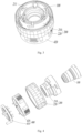
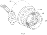
- an embodiment of the present disclosure discloses an external connection device 300 for connecting an eyepiece 100 to an external functional component, so as to realize the function expansion of the eyepiece 100, which can thus be used in different scenarios.
- the eyepiece 100 may be an eyepiece structure of a camera, a weapon sight, etc.
- Corresponding functional component may include a focusing component, a night vision component (such as a thermal imaging night vision device, etc.), a filter component, etc.
- the external connection device 300 disclosed in the embodiment of the present disclosure includes a main body part 310 and a locking mechanism 320.
- the main body part 310 is the main member of the external connection device 300, and the external connection device 300 is connected to the eyepiece 100 and the functional component based on the main body part 310.
- the main body part 310 is a cylindrical structural member, that is, the main body part 310 is hollow inside and has an accommodating space, which may be used to accommodate the functional component.
- the functional component When the functional component is accommodated in the main body part 310, the functional component may damage the eyepiece 100 due to its contact with the eyepiece 100 inside the main body part 310. At the same time, the imaging quality will be affected if the space between them is too small.
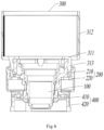
- the inner surface of the main body part 310 is provided with a separation portion 311 arranged in a ring shape, which separates the main body part 310 into a connecting section 312 and a mounting section 313. It should be understood that with such an arrangement, the separation portion 311 is located between the eyepiece 100 and the functional component, so that the eyepiece 100 and the functional component may be separated from each other, and the contact between them can be avoided.
- the main body part 310 is connected to the eyepiece 100 via the mounting section 313, and the functional component is located within the connecting section 312. The eyepiece 100 or functional component may be supported by abutting against the separation portion 311.
- the presence of the separation portion 311 can increase the distance between the eyepiece 100 and the functional component, which is beneficial for the functional component to act on the eyepiece 100 normally without affecting the imaging quality of the eyepiece 100.
- the separation portion 311 is arranged in a ring shape, that is to say, there is an avoidance space in the middle of the separation portion 311 for light propagation, and the separation portion 311 will not hinder the transmission of light in the main body part 310, and external light can enter the eyepiece 100 through the avoidance space, so as to form images in the eyes of the user.
- the side wall of the connecting section 312 is provided with a notch region 312a and a deformation gap 312b that is arranged in the circumferential direction of the connecting section 312, the notch region 312a is in connection with the deformation gap 312b, and is extended to an end of the connecting section 312 away from the mounting section 313; with such an arrangement, the connecting section 312 forms a first hold hoop part 312c and a second hold hoop part 312d on two sides of the notch region 312a respectively.
- the first hold hoop part 312c and the second hold hoop part 312d are separated from each other, so that deformation will occur when the first hold hoop part 312c and the second hold hoop part 312d are stressed.
- the first hold hoop part 312c and the second hold hoop part 312d are each a part of the side wall of the connecting section 312
- the side wall of the connecting section 312 will also be deformed, thus changing the size of the internal accommodation space of the connecting section 312.
- the size of the functional component is large, the internal accommodation space of the connecting section 312 may be increased for adaption, and when the size of the functional component is small, the internal accommodation space of the connecting section 312 may be reduced for adaption.
- the locking mechanism 320 as the control member of the external connection device 300, can be used to adjust the internal accommodation space of the connecting section 312.
- the locking mechanism 320 is connected to the first hold hoop part 312c and the second hold hoop part 312d respectively, and is configured for locking the first hold hoop part 312c and the second hold hoop part 312d, so that the connecting section 312 clamps and fixes the functional component. It should be understood that when the functional component is located in the accommodation space of the connecting section 312, the connecting section 312 cannot apply a sufficient action force on the functional component to generate frictional resistance to prevent the functional component from being disengaged from the connecting section 312. In this case, the stability and reliability of the connection between the functional component and the external connection device 300 are low.
- the first hold hoop part 312c and the second hold hoop part 323d can be locked based on the locking mechanism 320, that is, the first hold hoop part 312c and the second hold hoop part 312d can be kept in a stable state to maintain the deformation at that time; the deformation of the first hold hoop part 312c and the second hold hoop part 312d makes them move in the circumferential direction of the connecting section 312, thus changing the size of the notch region 312a.
- the notch region 312a needs to be reduced, the accommodation space in the connecting section 312 will be reduced, so that the accommodation space of the connecting section 312 will be matched with the functional component.
- the first hold hoop part 312c and the second hold hoop part 312d will not continue to deform in the locked state, so that the connecting section 312 can stably and sufficiently clamp and fix the functional component.
- the deformation degree of the first hold hoop part 312c and the second hold hoop part 312d is adjusted adaptively, so that the size of the accommodation space of the connecting section 312 is adapted with the functional component.
- the main body part 310 is separated into a connecting section 312 and a mounting section 313 by the separation portion 311, and is connected to the eyepiece 100 via the mounting section 313, and connected to the external functional component through the connecting section 312, thus realizing the functional expansion of the eyepiece 100.
- the connecting section 312 is provided with a notch region 312a, and a first hold hoop part 312c and a second hold hoop part 312d are formed on two sides of the notch region 312a.
- first hold hoop part 312c and the second hold hoop part 312d may move in the circumferential direction of the connecting section 312 to change the size of the notch region 312a, locking the first hold hoop part 312c and the second hold hoop part 312d relatively by a locking mechanism 320 may reduce the size of the notch region 312a, which may reduce the accommodation space in the connecting section 312, and then enabling the connecting section 312 to clamp and fix the functional component.
- the external connection device 300 disclosed in the embodiment of the present disclosure can undoubtedly adjust the size of the internal accommodation space of the connecting section 312 to adapt to functional components of different sizes, so it has better applicability.
- the locking mechanism 320 may be a clamping structure arranged on the outer sides of the first and second hold hoop parts 312c and 312d respectively.
- the first hold hoop part 312c and the second hold hoop part 312d may be clamped in opposite directions in use, thereby changing the size of the notch region 312a to change the size of the accommodation space of the connecting section 312.
- the first hold hoop part 312c may be provided with a first extension portion 312c1 in the radial direction of the main body part 310
- the second hold hoop part 312d may be provided with a second extension portion 312d1 in the radial direction of the main body part 310.
- the first extension portion 312c1 is provided opposite to the second extension portion 312d1
- the locking mechanism 320 is connected to the first extension portion 312c1 and the second extension portion 312d1 respectively, and is configured for locking the first extension portion 312c1 and the second extension portion 312d1.
- first hold hoop part 312c and the second hold hoop part 312d are both around the central axis of the main body part 310, and they are large in size, it is not convenient for them to apply action forces uniformly and intensively, which leads to poor locking effects.
- the force can be applied more intensively, since the first extension portion 312c1 and the second extension portion 312d1 are oppositely arranged, the first extension portion 312c1 and the second extension portion 312d1 may move towards each other with the locking mechanism 320, thereby changing (usually reducing) the size of the notch region 312a and further changing the size of the accommodation space of the connecting section 312.
- first extension portion 312c1 may be provided with a first through hole
- second extension portion 312d1 may be provided with a second through hole
- the locking mechanism 320 includes a connecting element 321 and a locking element 322.
- the connecting element 321 is provided through the first through hole and the second through hole, and is engaged with the first extension portion 312c1 at a side of the first through hole away from the second extension portion 312d1 for positional restriction.
- the locking element 322 can lock the second extension portion 312d1 at a side of the second through hole away from the first extension portion 312c1.
- the connecting element 321 abuts against the first extension portion 312c1 at the side of the first through hole away from the second extension portion 312d1
- the locking element 322 may apply an action force to the second extension portion 312d 1 at the side of the second through hole away from the first extension portion 312c1, so that the first extension portion 312c1 and the second extension portion 312d1 are closer to each other.
- the first hold hoop part 312c and the second hold hoop part 312d will be deformed accordingly, which changes the size of the accommodation space of the connecting section 312.
- the locking element 322 is locked against the second extension portion 312d, so that the first hold hoop part 312c and the second hold hoop part 312d are in a stable state, and the deformation degree at that time is maintained. In this way, the stable and sufficient clamping and fixing effect of the connecting section 312 on the functional component can be maintained, and the functional component can be prevented from loosening and being disengaged from the connecting section 312.
- the connecting element 321 may be selected as a threaded rod
- the locking element 322 may be selected as a lock nut.
- the lock nut is in a threaded connection with the threaded rod to achieve threaded transmission, and abuts against the second extension portion 312d1.
- the second extension portion 312d1 may be pushed to move toward the first extension portion 312c1, and then drive the first hold hoop part 312c and the second hold hoop part 312d to be deformed.
- the specific types of the connecting element 321 and the locking element 322 are not limited in the embodiment.
- the connecting element 321 may also be selected as a connecting rod, and the locking element 322 may be selected as a positioning pin, and the connecting rod may be provided with positioning holes at different positions.
- the positioning of the second extension portion 312d1 is limited by the engagement between the positioning pin with different positioning holes, thereby locking the first extension portion 312c1 and the second extension portion 312d 1, so as to ensure that the first hold hoop part 312c1 and the second extension portion 312d1 are deformed by required levels.
- the connecting element 321 is engaged with the first extension portion 312c1 at the side of the first through hole away from the second extension portion 312d1 for positional restriction.
- Such engagement for positional restriction can be realized by the connecting element 321 in many ways.
- the connecting element 321 may be provided with a limiting protrusion, via which the connecting element 321 may be in snap-fit engagement with the first extension portion 312c1.
- the limiting protrusion is usually arranged at an end of the connecting element 321, but it may also be arranged on the outer wall of the middle peripheral side of the connecting element 321. That is, the engagement for positional restriction between the connecting element 321 and the first extension portion 312c1 may be realized at an end of the connecting element 321 or in other areas of the connecting element 321.
- the locking mechanism 320 may further include a limiting element 323, which is connected to the connecting element 321 at the side of the first through hole away from the second extension portion 312d1, and via which the connecting element 321 is engaged with the first extension portion 312c1 for positional restriction.
- the limiting element 323, as an independent element, undoubtedly improves the convenience of assembling and disassembling the locking mechanism 320.
- limiting elements 323, such as threaded fasteners, limiting blocks installed in a snap connection manner, etc.
- the limiting element 323 may be a cam handle, which includes a cam portion 323a and a handle section 323b extending from the cam portion 323a.
- the cam portion 323a is rotatably connected to the connecting element 321, and the rotation axis of the cam portion 323a is perpendicular to the central axis of the first through hole.
- cam portion 323a has a partial base circle profile and a partial convex profile, as shown in Fig. 2 .
- the base circle profile abuts against the first extension portion 312c1, while the convex profile is further away from the first extension portion 312c1 compared with the base circle profile.
- the convex profile will gradually rotate to abut against the first extension portion 312c1, and will drive the first extension portion 312c1 to move towards the second extension portion 312d1 by a first distance, which is the difference in the size between the convex profile and the base circle profile.
- the first hold hoop part 312c and the second hold hoop part 312d may be tightened in a small range, so as to reduce the size of the accommodation space of the connecting section 312 to adapt to a smaller functional component.
- the convex profile When the handle section 323b is rotated in a second direction opposite to the first direction to rotate the cam portion 323a, during one rotation stroke of the cam portion 323a, the convex profile will gradually rotate in a direction away from the first extension portion 312c1, and the driving effect of the convex profile on the first extension portion 312c1 will gradually disappear, and the base circle profile will gradually abut against the second extension portion 312d1.
- the first extension portion 312c1 moves by a first distance away from the second extension portion 321d1. In this way, the first hold hoop part 312c and the second hold hoop part 312d may be loosened in a small range, so that the accommodation space of the connecting section 312 may be enlarged to adapt to a larger functional component.
- the extension direction of the handle section 323b may be parallel to the central axis of the main body part 310.
- the handle section 323b will not interfere with the main body part 310 in its extension direction, thus avoiding the interference to the normal use of the external connection device 300, and at the same time ensuring that the handle section 323b can drive the cam portion 323a to make a complete rotation stroke.
- an embodiment of the present disclosure further discloses an eyepiece module, which includes an eyepiece 100, a connecting assembly 200 and the aforementioned external connection device 300.
- the eyepiece 100 is connected to the mounting section 313 via the connecting assembly 200.
- the external connection device 300 can be installed on the eyepiece 100 via the connecting assembly 200 in actual use, which can realize the extension of the external connection function of the eyepiece 100.
- the specific structural type of the connecting assembly 200 is not limited in the embodiment, and the connecting assembly 200 can engage the eyepiece 100 with the mounting section 313 by clamping, bonding, screwing, etc..
- the connecting assembly 200 may include a connecting ring 210 and a locking ring 220.
- the connecting ring 210 may be used as an installation basis of the eyepiece 100, which is usually sleeved on the peripheral side of the eyepiece 100, and in which an installation groove matched with the external lens barrel of the eyepiece 100 may be arranged to install and fix the eyepiece 100.
- the locking ring 220 is usually sleeved outside the connecting ring 210, and is movably connected to the connecting ring 210, that is, the locking ring 220 can move relative to the connecting ring 210.
- the outer surface of the mounting section 313 may be provided with an external thread region
- the inner surface of the locking ring 220 may be provided with an internal thread region
- the mounting section 313 may be in threaded engagement with the locking ring 220 via the external thread region and the internal thread region of the locking ring 220.
- the fixed connection between the mounting section 313 and the locking ring 220 may be realized based on the threaded engagement between the external thread region and the internal thread region, that is, the engagement between the external connection device 300 and the eyepiece 100 is realized.
- the mounting section 313 and the locking ring 220 may be separated by screwing the external thread region out of the internal thread region. At this time, the external connection device 300 is also removed from the connecting assembly 200.
- the inner surface of the mounting section 313 may be provided with at least one first engagement portion 313a
- the connecting ring 210 is provided with a second engagement portion(s) 211 the number of which is same as that of the at least one first engagement portion 313a
- the first engagement portion 313a may be in snap-fit engagement with the second engagement portion 211. It should be understood that the first engagement portion 313a and the second engagement portion 211 are in one-to-one correspondence. After the first engagement portion 313a and the second engagement portion 211 are in snap-fit engagement one by one, the engagement between the mounting section 313 and the connecting ring 210 is realized.
- the mounting section 313 is connected to the connecting ring 210 and the locking ring 220 in the connecting assembly 200 at the same time, thus ensuring the reliable installation of the external connection device and the connecting assembly 200.
- the first engagement portion 313a is arranged on the inner surface of the mounting section 313, and the external thread region is arranged on the outer surface of the mounting section 313, therefore they will not interfere with each other when realizing the engagement with the second engagement portion 211 and the internal thread region of the locking ring 220.
- the specific number of the first engagement portion 313a and the second engagement portion 211 is not limited in the embodiment, which can be provided as one or more.
- the specific types of the first engagement portion 313a and the second engagement portion 211 are not limited in the embodiment, as long as they can in snap-fit engagement.
- one of the first engagement portion 313a and the second engagement portion 211 may be a protruding structure and the other may be an indent structure, and the protruding structure and the indent structure can realize the snap-fit engagement.
- one of the first engagement portion 313a and the second engagement portion 211 is a snap-fit protrusion, and the other is an L-shaped snap-fit groove.
- the second engagement portion 211 is an L-shaped snap-fit groove
- the first engagement portion 313a is an L-shaped snap-fit groove
- the second engagement portion 211 is a snap-fit protrusion.
- the first engagement portion 313a is a snap-fit protrusion and the second engagement portion 211 is an L-shaped snap-fit groove.
- the snap-fit protrusion may be realized by providing a projecting pin on the inner surface of the mounting section 313.
- the L-shaped snap-fit groove is provided with a first guide groove and a second guide groove which are intersected each other, and the snap-fit protrusion can smoothly enter the L-shaped snap-fit groove via the first guide groove, and then can be in snap-fit engagement with the L-shaped snap-fit groove by screwing the snap-fit protrusion into the second guide groove. Based on the structural characteristics of the L-shaped snap-fit groove, the accidental separation of the first engagement portion 313a from the second engagement portion 211 can be avoided, which can improve the connection reliability between the mounting section 313 and the connecting ring 210.
- the second engagement portion 211 can be evenly arranged on the connecting ring 210 in multiple groups, and the first engagement portion 313a can be smoothly engaged with different second engagement portions 211. Therefore, there are multiple engagement ways, which can be realized by simply rotating the external connection device at a certain angle in its circumferential direction.
- the cam handle is randomly arranged in the circumferential direction of the main body part 310, which is inconvenient to operate, and meanwhile it may interfere with other structures at different positions, the cam handle is generally arranged at a circumferentially fixed position of the main body part 310.
- a plurality of second engagement portions 211 are unevenly arranged on the connecting ring 210.
- the mounting assembly 400 includes a fixing ring 410 and a mounting ring 420, wherein the fixing ring 410 is sleeved on the peripheral side of the eyepiece 100, the mounting ring 420 is sleeved outside the fixing ring 410, and the mounting ring 420 is movably connected to the fixing ring 410.
- the fixing ring 410 may generally be in snap-fit engagement with the apparatus to which the eyepiece 100 is applied, thereby preventing the eyepiece 100 from rotating in the circumferential direction on the applied apparatus.
- the mounting ring 420 may generally be in threaded engagement with the applied apparatus, so that the eyepiece 100 can be fixedly mounted on the applied apparatus.
- an embodiment of the present disclosure also discloses a hand-held apparatus, which includes the aforementioned external connection device 300 or the aforementioned eyepiece module.
- a hand-held apparatus which includes the aforementioned external connection device 300 or the aforementioned eyepiece module.
- there are many types of hand-held apparatuses such as cameras, weapons with sights, microscopic observation devices, etc.
Landscapes
- Physics & Mathematics (AREA)
- General Physics & Mathematics (AREA)
- Optics & Photonics (AREA)
- Engineering & Computer Science (AREA)
- General Engineering & Computer Science (AREA)
- Mutual Connection Of Rods And Tubes (AREA)
- Telescopes (AREA)
- Studio Devices (AREA)
Claims (10)
- Dispositif de connexion externe pour connecter un oculaire à un composant fonctionnel externe, dans lequel le dispositif de connexion externe (300) comprend une partie de corps principal (310) et un mécanisme de verrouillage (320), dans lequel la partie de corps principal (310) est un élément structural cylindrique, une section de connexion (312) et une section de montage (313), et la partie de corps principal (310) est connectée à l'oculaire (100) par le biais de la section de montage (313) ;une paroi latérale de la section de connexion (312) est munie d'une région d'encoche (312a) s'étendant jusqu'à une extrémité de la section de connexion (312) à distance de la section de montage (313), et la section de connexion (312) forme une première partie de cerceau de maintien (312c) et une seconde partie de cerceau de maintien (312d) sur deux côtés de la région d'encoche (312a) respectivement ; le mécanisme de verrouillage (320) est connecté à la première partie de cerceau de maintien (312c) et à la seconde partie de cerceau de maintien (312d) respectivement, et est configuré pour verrouiller la première partie de cerceau de maintien (312c) et la seconde partie de cerceau de maintien (312d) de sorte que la section de connexion (312) serre et fixe le composant fonctionnelcaractérisé en ce queune surface intérieure dudit corps principal (310) est munie d'une partie de séparation (311) agencée en forme d'anneau, qui sépare ladite partie de corps principal (310) en ladite section de connexion (312) et ladite section de montage (313) ; en ce queladite paroi latérale de ladite section de connexion (312) est munie d'un espace de déformation (312b) qui est agencé dans une direction circonférentielle de la section de connexion (312), et en ce queladite région d'encoche (312a) est en liaison avec ledit espace de déformation (312b).
- Dispositif de connexion externe selon la revendication 1, dans lequel la première partie de cerceau de maintien (312c) est munie d'une première partie d'extension (312c1) dans une direction radiale de la partie de corps principal (310), et la seconde partie de cerceau de maintien (312d) est munie d'une seconde partie d'extension (312d1) dans la direction radiale de la partie de corps principal (310), la première partie d'extension (312c1) est disposée à l'opposé de la seconde partie d'extension (312d1), le mécanisme de verrouillage (320) est connecté à la première partie d'extension (312c1) et à la seconde partie d'extension (312d1) respectivement, et est configuré pour verrouiller la première partie d'extension (312c1) et la seconde partie d'extension (312d1).
- Dispositif de connexion externe selon la revendication 2, dans lequel la première partie d'extension (312c1) est munie d'un premier trou traversant, et la seconde partie d'extension (312d1) est munie d'un second trou traversant ; le mécanisme de verrouillage (320) comprend un élément de connexion (321) et un élément de verrouillage (322), dans lequel l'élément de connexion (321) est disposé à travers le premier trou traversant et le second trou traversant, et est en prise avec la première partie d'extension (312c1) sur un côté du premier trou traversant à distance de la seconde partie d'extension (312d1) pour une restriction de position, et l'élément de verrouillage (322) peut verrouiller la seconde partie d'extension (312d1) sur un côté du second trou traversant à distance de la première partie d'extension (312c1).
- Dispositif de connexion externe selon la revendication 3, dans lequel le mécanisme de verrouillage (320) comprend en outre un élément de limitation (323) qui est connecté à l'élément de connexion (321) sur le côté du premier trou traversant à distance de la seconde partie d'extension (312d1), et par le biais duquel l'élément de connexion (321) est en prise avec la première partie d'extension (312c1) pour une restriction de position.
- Dispositif de connexion externe selon la revendication 4, dans lequel l'élément de limitation (323) est une poignée à came qui comprend une partie de came (323a) et une section de poignée (323b) s'étendant à partir de la partie de came (323a), et la partie de came (323a) est connectée de manière rotative à l'élément de connexion (321), et un axe de rotation de la partie de came (323a) est perpendiculaire à un axe central du premier trou traversant.
- Dispositif de connexion externe selon la revendication 5, dans lequel une direction d'extension de la section de poignée (323b) est parallèle à un axe central de la partie de corps principal (310).
- Module oculaire, comprenant un oculaire (100), un ensemble de connexion (200) et le dispositif de connexion externe (300) selon l'une quelconque des revendications 1 à 6, dans lequel l'oculaire (100) est connecté à la section de montage (313) par le biais de l'ensemble de connexion (200).
- Module oculaire selon la revendication 7, dans lequel une surface extérieure de la section de montage (313) est munie d'une région de filetage externe, et une surface intérieure de la section de montage (313) est munie d'au moins une première partie de mise en prise (313a) ; l'ensemble de connexion (200) comprend une bague de connexion (210) et une bague de verrouillage (220), dans lequel la bague de connexion (210) est emmanchée sur un côté périphérique de l'oculaire (100), la bague de verrouillage (220) est emmanchée à l'extérieur de la bague de connexion (210), et est reliée de manière mobile à la bague de connexion (210) ; la bague de connexion (210) est munie d'une ou de secondes parties de mise en prise (211), dont le nombre est le même que celui de la au moins une première partie de mise en prise (313a), et une surface intérieure de la bague de verrouillage (220) est munie d'une région de filetage interne ;
la section de montage (313) peut être en prise filetée avec la bague de verrouillage (220) par le biais de la région de filetage externe et la région de filetage interne, et la première partie de mise en prise (313a) peut être en prise par encliquetage avec la seconde partie de mise en prise (211). - Module oculaire selon la revendication 8, dans lequel l'une de la première partie de mise en prise (313a) et de la seconde partie de mise en prise (211) est une saillie d'encliquetage et l'autre est une rainure d'encliquetage en L.
- Appareil portatif comprenant le dispositif de connexion externe selon l'une quelconque des revendications 1 à 6, ou comprenant le module oculaire selon l'une quelconque des revendications 7 à 9.
Applications Claiming Priority (2)
| Application Number | Priority Date | Filing Date | Title |
|---|---|---|---|
| CN202021216078.4U CN212135037U (zh) | 2020-06-28 | 2020-06-28 | 外接装置、目镜模组及手持设备 |
| PCT/CN2021/080574 WO2022001180A1 (fr) | 2020-06-28 | 2021-03-12 | Dispositif de connexion externe, module oculaire et appareil portatif |
Publications (3)
| Publication Number | Publication Date |
|---|---|
| EP4174548A1 EP4174548A1 (fr) | 2023-05-03 |
| EP4174548A4 EP4174548A4 (fr) | 2024-01-03 |
| EP4174548B1 true EP4174548B1 (fr) | 2025-01-22 |
Family
ID=73686187
Family Applications (1)
| Application Number | Title | Priority Date | Filing Date |
|---|---|---|---|
| EP21832388.9A Active EP4174548B1 (fr) | 2020-06-28 | 2021-03-12 | Dispositif de connexion externe, module oculaire et appareil portatif |
Country Status (3)
| Country | Link |
|---|---|
| EP (1) | EP4174548B1 (fr) |
| CN (1) | CN212135037U (fr) |
| WO (1) | WO2022001180A1 (fr) |
Families Citing this family (2)
| Publication number | Priority date | Publication date | Assignee | Title |
|---|---|---|---|---|
| CN212135037U (zh) * | 2020-06-28 | 2020-12-11 | 杭州海康微影传感科技有限公司 | 外接装置、目镜模组及手持设备 |
| CN113152052B (zh) * | 2021-02-22 | 2025-08-29 | 小熊电器股份有限公司 | 一种烫熨板可调节的挂烫机 |
Family Cites Families (11)
| Publication number | Priority date | Publication date | Assignee | Title |
|---|---|---|---|---|
| CN2427822Y (zh) * | 2000-06-20 | 2001-04-25 | 王以忠 | 光学器材转接头 |
| JP2009251336A (ja) * | 2008-04-08 | 2009-10-29 | Tamron Co Ltd | レンズマウント機構及びレンズ鏡筒 |
| CN203858404U (zh) * | 2014-05-15 | 2014-10-01 | 蔡彬 | 接目取景放大镜连接件 |
| US9977313B2 (en) * | 2016-08-05 | 2018-05-22 | Global Boom International Limited | Lens adapter and its back-locking lens fixing device |
| DE102016117805A1 (de) * | 2016-09-21 | 2018-03-22 | Henke-Sass, Wolf Gmbh | Endoskop und Verfahren zum Zentrieren eines Okulars in einem Hauptteil eines Endoskops |
| CN206332726U (zh) * | 2016-12-12 | 2017-07-14 | 杭州艾斯基光学仪器有限公司 | 一种连接手机的目镜转接头 |
| CN207112322U (zh) * | 2017-04-21 | 2018-03-16 | 深圳市大疆灵眸科技有限公司 | 云台支架 |
| CN108845473A (zh) * | 2018-08-15 | 2018-11-20 | 苏州康普雷森精密机械有限公司 | 一种相机镜头拼接组合部件 |
| CN208588890U (zh) * | 2018-08-29 | 2019-03-08 | 辉映摄影器材有限公司 | 一种镜头转接组件 |
| CN111258020B (zh) * | 2020-01-14 | 2021-05-18 | 中国科学院长春光学精密机械与物理研究所 | 螺纹锁紧结构及调焦镜头组件 |
| CN212135037U (zh) * | 2020-06-28 | 2020-12-11 | 杭州海康微影传感科技有限公司 | 外接装置、目镜模组及手持设备 |
-
2020
- 2020-06-28 CN CN202021216078.4U patent/CN212135037U/zh active Active
-
2021
- 2021-03-12 EP EP21832388.9A patent/EP4174548B1/fr active Active
- 2021-03-12 WO PCT/CN2021/080574 patent/WO2022001180A1/fr not_active Ceased
Also Published As
| Publication number | Publication date |
|---|---|
| EP4174548A1 (fr) | 2023-05-03 |
| EP4174548A4 (fr) | 2024-01-03 |
| WO2022001180A1 (fr) | 2022-01-06 |
| CN212135037U (zh) | 2020-12-11 |
Similar Documents
| Publication | Publication Date | Title |
|---|---|---|
| EP4174548B1 (fr) | Dispositif de connexion externe, module oculaire et appareil portatif | |
| JP5779179B2 (ja) | レンズユニット | |
| US11408553B2 (en) | Tripod stand head mount | |
| US10254506B2 (en) | Lens apparatus and image pickup apparatus | |
| US8593742B2 (en) | Screw-mount lens barrel | |
| US8300334B2 (en) | Variable power lens | |
| US10447904B2 (en) | Lens mount for use in attachment/removal of interchangeable lens, interchangeable lens, and image pickup apparatus | |
| JP3915020B2 (ja) | ズームレンズ装置のレンズ鏡筒構造 | |
| US20220239806A1 (en) | Scope phone mount | |
| US20200225439A1 (en) | Imaging device | |
| US7423815B2 (en) | Adjustable lens device | |
| US10088648B2 (en) | Binoculars | |
| US20240019768A1 (en) | Camera device | |
| US12235511B2 (en) | Adapter | |
| JP4208811B2 (ja) | ロック機構付きレンズ鏡筒 | |
| JP2025061054A (ja) | レンズ鏡筒 | |
| JP5567987B2 (ja) | レンズの倒れ調整装置およびレンズ鏡筒 | |
| JP7777367B2 (ja) | 変倍照準器 | |
| KR0138733B1 (ko) | 나사 장착대를 가진 렌즈 경통 | |
| CN116164584B (zh) | 变倍瞄准镜 | |
| JP6415425B2 (ja) | レンズ装置 | |
| JP5529243B2 (ja) | 締結具 | |
| KR101313860B1 (ko) | 광학장치 | |
| US7612958B2 (en) | Telescopic sight | |
| JP3091997B2 (ja) | ねじマウントレンズ鏡筒 |
Legal Events
| Date | Code | Title | Description |
|---|---|---|---|
| STAA | Information on the status of an ep patent application or granted ep patent |
Free format text: STATUS: THE INTERNATIONAL PUBLICATION HAS BEEN MADE |
|
| PUAI | Public reference made under article 153(3) epc to a published international application that has entered the european phase |
Free format text: ORIGINAL CODE: 0009012 |
|
| STAA | Information on the status of an ep patent application or granted ep patent |
Free format text: STATUS: REQUEST FOR EXAMINATION WAS MADE |
|
| 17P | Request for examination filed |
Effective date: 20230110 |
|
| AK | Designated contracting states |
Kind code of ref document: A1 Designated state(s): AL AT BE BG CH CY CZ DE DK EE ES FI FR GB GR HR HU IE IS IT LI LT LU LV MC MK MT NL NO PL PT RO RS SE SI SK SM TR |
|
| DAV | Request for validation of the european patent (deleted) | ||
| DAX | Request for extension of the european patent (deleted) | ||
| A4 | Supplementary search report drawn up and despatched |
Effective date: 20231205 |
|
| RIC1 | Information provided on ipc code assigned before grant |
Ipc: G02B 7/02 20210101ALI20231129BHEP Ipc: F41G 11/00 20060101ALI20231129BHEP Ipc: G02B 25/00 20060101ALI20231129BHEP Ipc: G02B 7/00 20210101AFI20231129BHEP |
|
| GRAP | Despatch of communication of intention to grant a patent |
Free format text: ORIGINAL CODE: EPIDOSNIGR1 |
|
| STAA | Information on the status of an ep patent application or granted ep patent |
Free format text: STATUS: GRANT OF PATENT IS INTENDED |
|
| INTG | Intention to grant announced |
Effective date: 20240924 |
|
| GRAS | Grant fee paid |
Free format text: ORIGINAL CODE: EPIDOSNIGR3 |
|
| GRAA | (expected) grant |
Free format text: ORIGINAL CODE: 0009210 |
|
| STAA | Information on the status of an ep patent application or granted ep patent |
Free format text: STATUS: THE PATENT HAS BEEN GRANTED |
|
| AK | Designated contracting states |
Kind code of ref document: B1 Designated state(s): AL AT BE BG CH CY CZ DE DK EE ES FI FR GB GR HR HU IE IS IT LI LT LU LV MC MK MT NL NO PL PT RO RS SE SI SK SM TR |
|
| REG | Reference to a national code |
Ref country code: GB Ref legal event code: FG4D |
|
| REG | Reference to a national code |
Ref country code: CH Ref legal event code: EP |
|
| REG | Reference to a national code |
Ref country code: IE Ref legal event code: FG4D |
|
| REG | Reference to a national code |
Ref country code: DE Ref legal event code: R096 Ref document number: 602021025204 Country of ref document: DE |
|
| P01 | Opt-out of the competence of the unified patent court (upc) registered |
Free format text: CASE NUMBER: APP_11830/2025 Effective date: 20250311 |
|
| PGFP | Annual fee paid to national office [announced via postgrant information from national office to epo] |
Ref country code: AT Payment date: 20250417 Year of fee payment: 5 |
|
| REG | Reference to a national code |
Ref country code: NL Ref legal event code: MP Effective date: 20250122 |
|
| PG25 | Lapsed in a contracting state [announced via postgrant information from national office to epo] |
Ref country code: NL Free format text: LAPSE BECAUSE OF FAILURE TO SUBMIT A TRANSLATION OF THE DESCRIPTION OR TO PAY THE FEE WITHIN THE PRESCRIBED TIME-LIMIT Effective date: 20250122 |
|
| PG25 | Lapsed in a contracting state [announced via postgrant information from national office to epo] |
Ref country code: RS Free format text: LAPSE BECAUSE OF FAILURE TO SUBMIT A TRANSLATION OF THE DESCRIPTION OR TO PAY THE FEE WITHIN THE PRESCRIBED TIME-LIMIT Effective date: 20250422 |
|
| PG25 | Lapsed in a contracting state [announced via postgrant information from national office to epo] |
Ref country code: FI Free format text: LAPSE BECAUSE OF FAILURE TO SUBMIT A TRANSLATION OF THE DESCRIPTION OR TO PAY THE FEE WITHIN THE PRESCRIBED TIME-LIMIT Effective date: 20250122 |
|
| PG25 | Lapsed in a contracting state [announced via postgrant information from national office to epo] |
Ref country code: PL Free format text: LAPSE BECAUSE OF FAILURE TO SUBMIT A TRANSLATION OF THE DESCRIPTION OR TO PAY THE FEE WITHIN THE PRESCRIBED TIME-LIMIT Effective date: 20250122 |
|
| PG25 | Lapsed in a contracting state [announced via postgrant information from national office to epo] |
Ref country code: ES Free format text: LAPSE BECAUSE OF FAILURE TO SUBMIT A TRANSLATION OF THE DESCRIPTION OR TO PAY THE FEE WITHIN THE PRESCRIBED TIME-LIMIT Effective date: 20250122 |
|
| REG | Reference to a national code |
Ref country code: LT Ref legal event code: MG9D |
|
| PG25 | Lapsed in a contracting state [announced via postgrant information from national office to epo] |
Ref country code: NO Free format text: LAPSE BECAUSE OF FAILURE TO SUBMIT A TRANSLATION OF THE DESCRIPTION OR TO PAY THE FEE WITHIN THE PRESCRIBED TIME-LIMIT Effective date: 20250422 Ref country code: IS Free format text: LAPSE BECAUSE OF FAILURE TO SUBMIT A TRANSLATION OF THE DESCRIPTION OR TO PAY THE FEE WITHIN THE PRESCRIBED TIME-LIMIT Effective date: 20250522 |
|
| REG | Reference to a national code |
Ref country code: AT Ref legal event code: MK05 Ref document number: 1761885 Country of ref document: AT Kind code of ref document: T Effective date: 20250122 |
|
| PG25 | Lapsed in a contracting state [announced via postgrant information from national office to epo] |
Ref country code: HR Free format text: LAPSE BECAUSE OF FAILURE TO SUBMIT A TRANSLATION OF THE DESCRIPTION OR TO PAY THE FEE WITHIN THE PRESCRIBED TIME-LIMIT Effective date: 20250122 |
|
| PG25 | Lapsed in a contracting state [announced via postgrant information from national office to epo] |
Ref country code: PT Free format text: LAPSE BECAUSE OF FAILURE TO SUBMIT A TRANSLATION OF THE DESCRIPTION OR TO PAY THE FEE WITHIN THE PRESCRIBED TIME-LIMIT Effective date: 20250522 Ref country code: LV Free format text: LAPSE BECAUSE OF FAILURE TO SUBMIT A TRANSLATION OF THE DESCRIPTION OR TO PAY THE FEE WITHIN THE PRESCRIBED TIME-LIMIT Effective date: 20250122 |
|
| PG25 | Lapsed in a contracting state [announced via postgrant information from national office to epo] |
Ref country code: BG Free format text: LAPSE BECAUSE OF FAILURE TO SUBMIT A TRANSLATION OF THE DESCRIPTION OR TO PAY THE FEE WITHIN THE PRESCRIBED TIME-LIMIT Effective date: 20250122 Ref country code: GR Free format text: LAPSE BECAUSE OF FAILURE TO SUBMIT A TRANSLATION OF THE DESCRIPTION OR TO PAY THE FEE WITHIN THE PRESCRIBED TIME-LIMIT Effective date: 20250423 |
|
| PG25 | Lapsed in a contracting state [announced via postgrant information from national office to epo] |
Ref country code: AT Free format text: LAPSE BECAUSE OF FAILURE TO SUBMIT A TRANSLATION OF THE DESCRIPTION OR TO PAY THE FEE WITHIN THE PRESCRIBED TIME-LIMIT Effective date: 20250122 |
|
| PG25 | Lapsed in a contracting state [announced via postgrant information from national office to epo] |
Ref country code: SE Free format text: LAPSE BECAUSE OF FAILURE TO SUBMIT A TRANSLATION OF THE DESCRIPTION OR TO PAY THE FEE WITHIN THE PRESCRIBED TIME-LIMIT Effective date: 20250122 |
|
| PG25 | Lapsed in a contracting state [announced via postgrant information from national office to epo] |
Ref country code: SM Free format text: LAPSE BECAUSE OF FAILURE TO SUBMIT A TRANSLATION OF THE DESCRIPTION OR TO PAY THE FEE WITHIN THE PRESCRIBED TIME-LIMIT Effective date: 20250122 |
|
| PG25 | Lapsed in a contracting state [announced via postgrant information from national office to epo] |
Ref country code: DK Free format text: LAPSE BECAUSE OF FAILURE TO SUBMIT A TRANSLATION OF THE DESCRIPTION OR TO PAY THE FEE WITHIN THE PRESCRIBED TIME-LIMIT Effective date: 20250122 |
|
| PG25 | Lapsed in a contracting state [announced via postgrant information from national office to epo] |
Ref country code: MC Free format text: LAPSE BECAUSE OF FAILURE TO SUBMIT A TRANSLATION OF THE DESCRIPTION OR TO PAY THE FEE WITHIN THE PRESCRIBED TIME-LIMIT Effective date: 20250122 |
|
| PG25 | Lapsed in a contracting state [announced via postgrant information from national office to epo] |
Ref country code: IT Free format text: LAPSE BECAUSE OF FAILURE TO SUBMIT A TRANSLATION OF THE DESCRIPTION OR TO PAY THE FEE WITHIN THE PRESCRIBED TIME-LIMIT Effective date: 20250122 |
|
| PG25 | Lapsed in a contracting state [announced via postgrant information from national office to epo] |
Ref country code: EE Free format text: LAPSE BECAUSE OF FAILURE TO SUBMIT A TRANSLATION OF THE DESCRIPTION OR TO PAY THE FEE WITHIN THE PRESCRIBED TIME-LIMIT Effective date: 20250122 Ref country code: CZ Free format text: LAPSE BECAUSE OF FAILURE TO SUBMIT A TRANSLATION OF THE DESCRIPTION OR TO PAY THE FEE WITHIN THE PRESCRIBED TIME-LIMIT Effective date: 20250122 |
|
| REG | Reference to a national code |
Ref country code: CH Ref legal event code: H13 Free format text: ST27 STATUS EVENT CODE: U-0-0-H10-H13 (AS PROVIDED BY THE NATIONAL OFFICE) Effective date: 20251023 Ref country code: DE Ref legal event code: R097 Ref document number: 602021025204 Country of ref document: DE |
|
| PG25 | Lapsed in a contracting state [announced via postgrant information from national office to epo] |
Ref country code: RO Free format text: LAPSE BECAUSE OF FAILURE TO SUBMIT A TRANSLATION OF THE DESCRIPTION OR TO PAY THE FEE WITHIN THE PRESCRIBED TIME-LIMIT Effective date: 20250122 |
|
| PG25 | Lapsed in a contracting state [announced via postgrant information from national office to epo] |
Ref country code: SK Free format text: LAPSE BECAUSE OF FAILURE TO SUBMIT A TRANSLATION OF THE DESCRIPTION OR TO PAY THE FEE WITHIN THE PRESCRIBED TIME-LIMIT Effective date: 20250122 |
|
| PG25 | Lapsed in a contracting state [announced via postgrant information from national office to epo] |
Ref country code: LU Free format text: LAPSE BECAUSE OF NON-PAYMENT OF DUE FEES Effective date: 20250312 |
|
| PLBE | No opposition filed within time limit |
Free format text: ORIGINAL CODE: 0009261 |
|
| STAA | Information on the status of an ep patent application or granted ep patent |
Free format text: STATUS: NO OPPOSITION FILED WITHIN TIME LIMIT |
|
| REG | Reference to a national code |
Ref country code: BE Ref legal event code: MM Effective date: 20250331 |
|
| GBPC | Gb: european patent ceased through non-payment of renewal fee |
Effective date: 20250422 |
|
| 26N | No opposition filed |
Effective date: 20251023 |
|
| PG25 | Lapsed in a contracting state [announced via postgrant information from national office to epo] |
Ref country code: GB Free format text: LAPSE BECAUSE OF NON-PAYMENT OF DUE FEES Effective date: 20250422 |
|
| PG25 | Lapsed in a contracting state [announced via postgrant information from national office to epo] |
Ref country code: FR Free format text: LAPSE BECAUSE OF NON-PAYMENT OF DUE FEES Effective date: 20250322 |
|
| PG25 | Lapsed in a contracting state [announced via postgrant information from national office to epo] |
Ref country code: BE Free format text: LAPSE BECAUSE OF NON-PAYMENT OF DUE FEES Effective date: 20250331 |
|
| PG25 | Lapsed in a contracting state [announced via postgrant information from national office to epo] |
Ref country code: CH Free format text: LAPSE BECAUSE OF NON-PAYMENT OF DUE FEES Effective date: 20250331 |
|
| PG25 | Lapsed in a contracting state [announced via postgrant information from national office to epo] |
Ref country code: IE Free format text: LAPSE BECAUSE OF NON-PAYMENT OF DUE FEES Effective date: 20250312 |
|
| PGFP | Annual fee paid to national office [announced via postgrant information from national office to epo] |
Ref country code: DE Payment date: 20260313 Year of fee payment: 6 |