EP4174632B1 - Ein anzeigesystem für ein flugzeug - Google Patents
Ein anzeigesystem für ein flugzeug Download PDFInfo
- Publication number
- EP4174632B1 EP4174632B1 EP21290071.6A EP21290071A EP4174632B1 EP 4174632 B1 EP4174632 B1 EP 4174632B1 EP 21290071 A EP21290071 A EP 21290071A EP 4174632 B1 EP4174632 B1 EP 4174632B1
- Authority
- EP
- European Patent Office
- Prior art keywords
- display unit
- display
- default behavior
- behavior tag
- displayable
- Prior art date
- Legal status (The legal status is an assumption and is not a legal conclusion. Google has not performed a legal analysis and makes no representation as to the accuracy of the status listed.)
- Active
Links
Images



Classifications
-
- G—PHYSICS
- G06—COMPUTING OR CALCULATING; COUNTING
- G06F—ELECTRIC DIGITAL DATA PROCESSING
- G06F3/00—Input arrangements for transferring data to be processed into a form capable of being handled by the computer; Output arrangements for transferring data from processing unit to output unit, e.g. interface arrangements
- G06F3/14—Digital output to display device ; Cooperation and interconnection of the display device with other functional units
- G06F3/1423—Digital output to display device ; Cooperation and interconnection of the display device with other functional units controlling a plurality of local displays, e.g. CRT and flat panel display
-
- G—PHYSICS
- G01—MEASURING; TESTING
- G01C—MEASURING DISTANCES, LEVELS OR BEARINGS; SURVEYING; NAVIGATION; GYROSCOPIC INSTRUMENTS; PHOTOGRAMMETRY OR VIDEOGRAMMETRY
- G01C23/00—Combined instruments indicating more than one navigational value, e.g. for aircraft; Combined measuring devices for measuring two or more variables of movement, e.g. distance, speed or acceleration
- G01C23/005—Flight directors
-
- G—PHYSICS
- G01—MEASURING; TESTING
- G01C—MEASURING DISTANCES, LEVELS OR BEARINGS; SURVEYING; NAVIGATION; GYROSCOPIC INSTRUMENTS; PHOTOGRAMMETRY OR VIDEOGRAMMETRY
- G01C23/00—Combined instruments indicating more than one navigational value, e.g. for aircraft; Combined measuring devices for measuring two or more variables of movement, e.g. distance, speed or acceleration
-
- G—PHYSICS
- G06—COMPUTING OR CALCULATING; COUNTING
- G06F—ELECTRIC DIGITAL DATA PROCESSING
- G06F3/00—Input arrangements for transferring data to be processed into a form capable of being handled by the computer; Output arrangements for transferring data from processing unit to output unit, e.g. interface arrangements
- G06F3/14—Digital output to display device ; Cooperation and interconnection of the display device with other functional units
- G06F3/1454—Digital output to display device ; Cooperation and interconnection of the display device with other functional units involving copying of the display data of a local workstation or window to a remote workstation or window so that an actual copy of the data is displayed simultaneously on two or more displays, e.g. teledisplay
-
- G—PHYSICS
- G06—COMPUTING OR CALCULATING; COUNTING
- G06F—ELECTRIC DIGITAL DATA PROCESSING
- G06F9/00—Arrangements for program control, e.g. control units
- G06F9/06—Arrangements for program control, e.g. control units using stored programs, i.e. using an internal store of processing equipment to receive or retain programs
- G06F9/44—Arrangements for executing specific programs
- G06F9/445—Program loading or initiating
- G06F9/44505—Configuring for program initiating, e.g. using registry, configuration files
-
- G—PHYSICS
- G09—EDUCATION; CRYPTOGRAPHY; DISPLAY; ADVERTISING; SEALS
- G09G—ARRANGEMENTS OR CIRCUITS FOR CONTROL OF INDICATING DEVICES USING STATIC MEANS TO PRESENT VARIABLE INFORMATION
- G09G5/00—Control arrangements or circuits for visual indicators common to cathode-ray tube indicators and other visual indicators
- G09G5/14—Display of multiple viewports
-
- G—PHYSICS
- G01—MEASURING; TESTING
- G01D—MEASURING NOT SPECIALLY ADAPTED FOR A SPECIFIC VARIABLE; ARRANGEMENTS FOR MEASURING TWO OR MORE VARIABLES NOT COVERED IN A SINGLE OTHER SUBCLASS; TARIFF METERING APPARATUS; MEASURING OR TESTING NOT OTHERWISE PROVIDED FOR
- G01D2207/00—Indexing scheme relating to details of indicating measuring values
- G01D2207/10—Displays which are primarily used in aircraft or display aircraft-specific information
-
- G—PHYSICS
- G09—EDUCATION; CRYPTOGRAPHY; DISPLAY; ADVERTISING; SEALS
- G09G—ARRANGEMENTS OR CIRCUITS FOR CONTROL OF INDICATING DEVICES USING STATIC MEANS TO PRESENT VARIABLE INFORMATION
- G09G2310/00—Command of the display device
- G09G2310/04—Partial updating of the display screen
-
- G—PHYSICS
- G09—EDUCATION; CRYPTOGRAPHY; DISPLAY; ADVERTISING; SEALS
- G09G—ARRANGEMENTS OR CIRCUITS FOR CONTROL OF INDICATING DEVICES USING STATIC MEANS TO PRESENT VARIABLE INFORMATION
- G09G2354/00—Aspects of interface with display user
-
- G—PHYSICS
- G09—EDUCATION; CRYPTOGRAPHY; DISPLAY; ADVERTISING; SEALS
- G09G—ARRANGEMENTS OR CIRCUITS FOR CONTROL OF INDICATING DEVICES USING STATIC MEANS TO PRESENT VARIABLE INFORMATION
- G09G2380/00—Specific applications
- G09G2380/12—Avionics applications
Definitions
- the present invention relates to a display system for an aircraft and to an aircraft having such a display system.
- the present invention further relates to a method of configuring a display system of an aircraft.
- Display systems for aircrafts frequently include a plurality of display units.
- Respective display units of a given plurality of display units may be embodied as display screens or display surfaces. Such display screens or display surfaces may e. g. be located in a cockpit of a given aircraft.
- the respective display units may be allocated to different operator stations in the given aircraft. For instance, a first number of display units of the respective display units may be allocated to an operator station that is assigned to a pilot of the given aircraft and a second number of display units of the respective display units may be allocated to an operator station that is assigned to a co-pilot of the given aircraft, or to one or more other persons in the given aircraft, such as e. g. an observer and/or a crew member who conduct a particular flight mission, and so on.
- the first number of display units and the second number of display units may be controlled independent of each other by a suitable control unit so that respectively displayed information may differ on the first and second number of display units.
- the first and second number of display units may be synchronized by a suitable control unit such that respectively displayed information is identical on the first and second number of display units.
- the document US 2008/0246633 A1 describes a display system in an aircraft that includes a first number of display units which are allocated to a pilot's operator station assigned to a pilot of the aircraft, and a second number of display units which are allocated to a co-pilot's operator station assigned to a co-pilot of the aircraft.
- the first number of display units and the second number of display units display the same images, i. e. they are synchronized by a suitable control unit such that respectively displayed information is identical on the first and second number of display units.
- the document US 2016/0357492 A1 describes a similar display system in an aircraft that includes a first number of display units and a second number of display units. Again, the first number of display units and the second number of display units display the same images, i. e. they are synchronized by a suitable control unit such that respectively displayed information is identical on the first and second number of display units.
- the first number of display units and the second number of display units of a display system in an aircraft may be configured to display one or more displayable parameters, such as e. g. a decision altitude, a minimum decision altitude, a decision height, an upper altitude limit, an upper height limit, a heading, a course, a barometric value, and so on.
- a respective control unit associated with the display system may be embodied to control display of the one or more displayable parameters on the first number of display units and/or the second number of display units of the display system.
- Illustrative control units which control display of displayable parameters on display units of a display system in an aircraft are described in the documents EP 3 228 990 A1 and US 2009/0189787 A1 .
- the first number of display units and the second number of display units of a display system in an aircraft are usually separately configured by the associated control unit using dedicated configuration files when booting the display system.
- a first configuration file is required for the first number of display units and a second configuration file is required for the second number of display units.
- the configuration files are generally static, thus, preventing e. g. reconfiguration of the first number of display units and the second number of display units of a given display system to or during a particular flight mission.
- an object of the present invention to provide a new display system with a first number of display units and a second number of display units, which may easily and rapidly be reconfigured. It is a further object of the present invention to provide an aircraft having such a new display system, as well as a method of configuring such a new display system of an aircraft.
- a display system for an aircraft comprises at least one first display unit, at least one second display unit, a control unit that is configured to control the at least one first display unit and the at least one second display unit, and a storage unit with a main memory that is configured to store at least one configuration file that is useable by the control unit for configuration of the at least one first display unit and the at least one second display unit.
- the at least one configuration file defines at least one displayable parameter for the at least one first display unit and the at least one second display unit and comprises at least one default behavior tag associated with the at least one displayable parameter.
- the at least one default behavior tag defines a default behavior of the at least one first display unit and the at least one second display unit upon display of the at least one displayable parameter.
- the latter may be used to configure both the at least one first display unit and the at least one second display unit. Any required personalization of the configuration of the at least one first display unit and/or the at least one second display unit may be performed by means of the at least one default behavior tag.
- a single configuration file is provided that may be personalized by means of the at least one default behavior tag.
- a default behavior tag may preferably be associated with each displayable parameter defined in a given configuration file for at least one first display unit and at least one second display unit.
- the default behavior tag may have the form SLAVE [TRUE, FALSE].
- a slave mode is forced for the given displayable parameter such that display of the given displayable parameter is synchronized between the at least one first display unit and the at least one second display unit.
- an un-slave mode is forced for the given displayable parameter such that display of the given displayable parameter is not synchronized between the at least one first display unit and the at least one second display unit.
- each default behavior tag in the given configuration file is preferably initially set to a predetermined default value.
- synchronization or non-synchronization of the displayable parameters between the at least one first display unit and the at least one second display unit is initially pre-parameterized by means of the given configuration file which is stored in a main memory of the display system having the at least one first display unit and the at least one second display unit.
- the given configuration file only defines the following displayable parameters: decision altitude DA, minimum decision altitude MDA, decision height DH, upper altitude limit ALTLIM, and upper height limit HTLIM, as well as a default behavior tag in the form SLAVE [TRUE, FALSE] for each defined displayable parameter.
- the given configuration file comprises entries such as: DA SLAVE [TRUE, FALSE], MDA SLAVE [TRUE, FALSE], DH SLAVE [TRUE, FALSE], ALTLIM SLAVE [TRUE, FALSE], and HTLIM SLAVE [TRUE, FALSE].
- each default behavior tag in the given configuration file may be modified, e. g. via an associated human-machine interface, such as a touchscreen, a keyboard, one or more pushbuttons, switches and so on.
- an operator at an operator station to which the at least one first display unit or the at least one second display unit is associated such as a pilot at the pilot's operator station, may modify one or more default behavior tags.
- Each modified default behavior tag is then stored in a secondary memory associated with the display system, preferably in a non-volatile random-access memory (NVRAM). More specifically, the modified default behavior tags may be stored in an associated modified default behavior tag file in the NVRAM.
- the modified default behavior tags may be retrieved from the NVRAM and used to overwrite the default behavior tags from the given configuration file.
- these modified behavior tags are retrieved from the NVRAM and used to overwrite the initial default behavior tags from the given configuration file.
- the default behavior tags from the given configuration file are applied.
- a single tag may be provided that is suitable to define a default behavior and/or the modified behavior of each displayable parameter defined in the configuration file.
- an ALL SLAVE [TRUE, FALSE] parameter may be provided in the given configuration file or stored in NVRAM to force the behavior of the at least one first display unit and the at least one second display unit with respect to all displayable parameters.
- the storage unit further comprises a secondary memory that is configured to store at least one modified default behavior tag that is adapted to be used instead of the at least one default behavior tag.
- the secondary memory is a non-volatile random-access memory.
- the display system further comprises at least one human-machine interface that is configured to enable generation of the at least one modified default behavior tag and to cause storage of the at least one modified default behavior tag in the secondary memory.
- the at least one human-machine interface is associated with the at least one first display unit and/or the at least one second display unit.
- control unit is adapted to configure the at least one first display unit and the at least one second display unit using the at least one configuration file, wherein the control unit is further adapted to use the at least one modified default behavior tag instead of the at least one default behavior tag.
- the displayable parameter is one of a decision altitude, a minimum decision altitude, a decision height, an upper altitude limit, an upper height limit, a heading, a course, or a barometric value.
- the at least one default behavior tag and the at least one modified default behavior tag are respectively configured to cause either synchronization or non-synchronization of the at least one first display unit and the at least one second display unit upon display of the at least one displayable parameter.
- the at least one first display unit is associated with a first operator station of an aircraft, wherein the at least one second display unit is associated with a second operator station of the aircraft.
- the present invention further provides an aircraft comprising a new display system as described above.
- the present invention provides a method of configuring a display system of an aircraft.
- the display system comprises at least one first display unit, at least one second display unit, a control unit that is configured to control the at least one first display unit and the at least one second display unit, and a storage unit with a main memory and a secondary memory.
- the method comprises the following steps that are executed by means of the control unit: retrieving, from the main memory, at least one configuration file that is useable by the control unit for configuration of the at least one first display unit and the at least one second display unit, wherein the at least one configuration file defines at least one displayable parameter for the at least one first display unit and the at least one second display unit and comprises at least one default behavior tag associated with the at least one displayable parameter, and wherein the at least one default behavior tag defines a default behavior of the at least one first display unit and the at least one second display unit upon display of the at least one displayable parameter; configuring the at least one first display unit and the at least one second display unit using the at least one configuration file; retrieving, from the secondary memory, at least one modified default behavior tag that is provided to be used instead of the at least one default behavior tag; and using the at least one modified default behavior tag instead of the at least one default behavior tag for the at least one displayable parameter with the at least one first display unit and the at least one second display unit.
- the secondary memory is a non-volatile random-access memory.
- the displayable parameter is one of a decision altitude, a minimum decision altitude, a decision height, an upper altitude limit, an upper height limit, a heading, a course, or a barometric value.
- the at least one default behavior tag and the at least one modified default behavior tag are respectively configured to cause either synchronization or non-synchronization of the at least one first display unit and the at least one second display unit upon display of the at least one displayable parameter.
- the at least one first display unit is associated with a first operator station in an aircraft, wherein the at least one second display unit is associated with a second operator station in the aircraft.
- Figure 1 shows an aircraft 1 according to an embodiment of the present invention. More specifically, a front part of an airplane is shown, which illustratively forms the aircraft 1.
- the aircraft 1 comprises a fuselage 2 that forms two compartments.
- the two compartments may include a cockpit 2a and a cabin or cargo compartment 2b.
- the aircraft 1 comprises a display system 10.
- the display system 10 is preferably at least partly arranged in the cockpit 2a.
- the display system 10 is further described at Figure 2 and Figure 3 below.
- the aircraft 1 is only illustratively embodied as an airplane. However, the aircraft 1 may alternatively be embodied as a multicopter, a helicopter, or any other flying vehicle, as well as even a non-flying vehicle, in which the display system 10 as described in more detail hereinafter may be installed.
- FIG 2 shows the display system 10 of Figure 1 , which is formed according to an illustrative embodiment of the present invention.
- the display system 10 may include a display management system 12, as well as at least one and, illustratively, two human-machine interfaces (HMI) 14, 15.
- HMI human-machine interfaces
- the display management system 12 preferably comprises at least one first display unit (DU) 16 and at least one second display unit (DU) 18.
- the human-machine interfaces 14, 15 are preferably associated with the at least one first display unit 16 and/or the at least one second display unit 18.
- the human-machine interface 14 may be associated with the at least one first display unit 16 and the human-machine interface 15 may be associated with the at least one second display unit 18.
- a plurality of first display units 16 is provided, which is hereinafter only referred to as “the display units 16", for simplicity and brevity.
- a plurality of second display units 18 is provided, which is hereinafter only referred to as “the display units 18", for simplicity and brevity.
- Each one of the display units 16 and/or the display units 18 may be embodied as a display screen or a screen, or it may be formed by a display surface, a display area or a display window.
- the display units 16 illustratively form a first display units sub-assembly 21.
- the first display units sub-assembly 21 is preferably associated with a first operator station, such as e. g. the operator station of a pilot of the aircraft 1 of Figure 1 .
- the display units 18 form a second display units sub-assembly 29.
- the second display units sub-assembly 29 is preferably associated with a second operator station, such as e. g. the operator station of a co-pilot of the aircraft 1 of Figure 1 .
- the second operator station i. e. the second display units sub-assembly 29, may alternatively be associated with one or more other persons in the aircraft 1 instead of the co-pilot, such as e. g. an observer and/or a crew member who conduct a particular flight mission, and so on.
- the display management system 12 further comprises a control unit 20 and a storage unit 30.
- the storage unit 30 may be connected to the control unit 20 via a connection 27.
- the storage unit 30 is configured to store at least one configuration file (35 in Figure 3 ) that is useable by the control unit 20 for configuration of the display units 16 and the display units 18.
- the control unit 20 configures the display units 16 and the display units 18 for display of selected displayable parameters, such as e. g. a decision altitude DA, a minimum decision altitude MDA, a decision height DH, an upper altitude limit ALTLIM, an upper height limit HTLIM, a heading HDG, a course CRS, and/or a barometric value, such as e. g. an atmospheric pressure QFE or an altimeter sub-scale setting QNH.
- control unit 20 is preferably configured to control the display units 16 and the display units 18. Therefore, the control unit 12 may be connected to the display units 16 via connections 22 and to the display units 18 via connections 28.
- control unit 12 may be connected via connections 24, 26 to the human-machine interfaces 14, 15 to receive inputs from the human-machine interfaces 14, 15.
- Human-machine interfaces 14, 15 may e. g. include push-buttons, joysticks, pointing devices such as trackballs, touchscreens, etc. or any combination thereof.
- the control unit 20 may further be connected to a set of avionics computers.
- the control unit 20 may be connected to avionics computers of a flight management system that collects data, e. g. from databases, GPS sensors, pressure altimeters and so on, for display on the display units 16 and/or the display units 18.
- Figure 3 shows the storage unit 30 of Figure 2 with a main memory 34.
- the storage unit 30 further comprises a secondary memory 38.
- the secondary memory 38 is preferentially a non-volatile random-access memory (NVRAM).
- NVRAM non-volatile random-access memory
- the main memory 34 is preferably configured to store at least one configuration file 35 that is useable by the control unit 20 of Figure 2 for configuration of at least one of the display units 16 of Figure 2 and at least one of the display units 18 of Figure 2 .
- the at least one configuration file 35 is a single configuration file and, therefore, hereinafter referred to as "the configuration file 35", which is useable by the control unit 20 of Figure 2 for configuration of one of the display units 16 of Figure 2 , which is hereinafter referred to as "the reconfigurable display unit 16", and one of the display units 18 of Figure 2 , which is hereinafter referred to as "the reconfigurable display unit 18", for simplicity and clarity.
- one or more other configuration files may be provided for configuration of other ones of the display units 16 of Figure 2 and the display units 18 of Figure 2 and stored in the main memory 34.
- the configuration file 35 defines at least one displayable parameter 36 for the reconfigurable display unit 16 and the reconfigurable display unit 18.
- the configuration file 35 defines five displayable parameters, which are hereinafter referred to as "the predefined displayable parameters 36", for simplicity and clarity, i. e.: decision altitude DA, minimum decision altitude MDA, decision height DH, upper altitude limit ALTLIM, and upper height limit HTLIM.
- the configuration file 35 may further define all settings required for operation of the reconfigurable display unit 16 and the reconfigurable display unit 18 together with the predefined displayable parameters 36.
- the configuration file 35 further comprises at least one default behavior tag 37 associated with the predefined displayable parameters 36.
- the at least one default behavior tag 37 preferentially defines a default behavior of the reconfigurable display unit 16 and the reconfigurable display unit 18 upon display of an associated one of the predefined displayable parameters 36. More specifically, the at least one default behavior tag 37 is preferably configured to cause either synchronization or non-synchronization of the reconfigurable display unit 16 and the reconfigurable display unit 18 upon display of the predefined displayable parameters 36.
- the at least one default behavior tag 37 may have the form SLAVE [TRUE, FALSE], and one such default behavior tag may be provided for each one of the predefined displayable parameters 36.
- the configuration file 35 may define the following predefined displayable parameters 36 and associated default behavior tags 37: DA SLAVE [TRUE, FALSE], MDA SLAVE [TRUE, FALSE], DH SLAVE [TRUE, FALSE], ALTLIM SLAVE [TRUE, FALSE], and HTLIM SLAVE [TRUE, FALSE].
- each default behavior tag is initially set to a predefined value.
- DA SLAVE TRUE
- MDA SLAVE TRUE
- DH SLAVE TRUE
- ALTLIM SLAVE TRUE
- HTLIM SLAVE TRUE.
- the at least one default behavior tag 37 may be replaced with at least one modified default behavior tag 39 to enable personalization of the configuration file 35.
- the at least one modified default behavior tag 39 that is adapted to be used instead of the at least one default behavior tag 37 is preferably stored in the secondary memory 38 of the storage unit 30.
- At least one of the human-machine interfaces 14, 15 of Figure 2 is configured to enable generation of the at least one modified default behavior tag 39 and to cause storage of the at least one modified default behavior tag 39 in the secondary memory 38.
- the at least one of the human-machine interfaces 14, 15 may e. g. provide access to an editable version of the at least one modified default behavior tag 39 and/or the at least one default behavior tag 37.
- the at least one of the human-machine interfaces 14, 15 may provide a control panel accessing such an editable version.
- each editing of the editable version leads to a subsequent storing.
- the control unit 20 of Figure 2 is preferably adapted to configure the reconfigurable display unit 16 and the reconfigurable display unit 18 using the configuration file 35 and to use the at least one modified default behavior tag 39 instead of the at least one default behavior tag 37.
- the at least one modified default behavior tag 39 may e. g. be generated using the human-machine interfaces 14, 15 of Figure 2 .
- the at least one modified default behavior tag 39 may alternatively be generated in an aircraft-independent manner, e. g. by means of a general-purpose computer, and merely be stored in the secondary memory 38. In the latter case, different profiles with differing modified default behavior tags may even be created and e. g. used for differing flight missions, and so on.
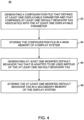
- Figure 4 shows an illustrative method 40 of providing on the one hand a configuration file with default behavior tags for configuring a display system of an aircraft, and on the other hand modified default behavior tags that may be used instead of the default behavior tags.
- the method 40 starts at step 42.
- a configuration file that defines at least one displayable parameter and that comprises at least one default behavior tag associated with the at least one displayable parameter is generated.
- the configuration file 35 of Figure 3 is generated, which defines the at least one displayable parameter 36 and the at least one default behavior tag 37.
- the configuration file 35 of Figure 3 with the predefined displayable parameters 36 and the associated default behavior tags 37 for configuration of the reconfigurable display units 16, 18 of Figure 2 is created.
- the generated configuration file is stored in a main memory of an associated display system.
- the configuration file 35 of Figure 3 is stored in the main memory 34 of Figure 3 of the display system 10 of Figure 2 of the aircraft 1 of Figure 1 .
- At step 46 at least one modified default behavior tag that is adapted to be used instead of the at least one stored default behavior tag is generated.
- the modified default behavior tags 39 of Figure 3 are created.
- the at least one generated modified default behavior tag is stored in a secondary memory of the associated display system.
- the modified default behavior tags 39 of Figure 3 are stored in the secondary memory 38 of Figure 3 of the display system 10 of Figure 2 of the aircraft 1 of Figure 1 .
- Figure 5 shows an illustrative method 50 of configuring a display system of an aircraft, wherein the display system comprises at least one first display unit, at least one second display unit, a control unit that is configured to control the at least one first display unit and the at least one second display unit, and a storage unit with a main memory and a secondary memory.
- the method 50 is preferably performed by means of the control unit and starts at step 52.
- the method 50 is described hereinafter in the context of the aircraft 1 of Figure 1 with the display system 10 of Figure 2 having the reconfigurable display units 16, 18, as well as the control unit 20 and the storage unit 30, with the main memory 34 and the secondary memory 38 of Figure 3 .
- the configuration file 35 with the predefined displayable parameters 36 and the associated default behavior tags 37 are stored, and in the secondary memory 38 the modified default behavior tags 39 are stored.
- control unit 20 retrieves the configuration file 35 that is useable by the control unit 20 for configuration of the reconfigurable display units 16, 18 from the main memory 34.
- control unit 20 configures the reconfigurable display units 16, 18 using the configuration file 35.
- control unit 20 retrieves, from the secondary memory 38, the modified default behavior tags 39 which are provided to be used instead of the default behavior tags 37.
- control unit 20 uses the modified default behavior tags 39 instead of the default behavior tags 37 for the displayable parameters 36 with the reconfigurable display units 16, 18.
- synchronization or non-synchronization of displayable parameters is described in detail with respect to separate display units.
- a respective synchronization may e. g. be performed between a display unit and other means, such as e. g. a GPS system, a database such as an aeronautical database, a NOTAM system, a machine learning unit, and so on.
- a GPS system e. g. a GPS system
- a database such as an aeronautical database
- NOTAM system e.g.
- machine learning unit e.g. a respective synchronization may e. g. be performed between a display unit and other means, such as e. g. a GPS system, a database such as an aeronautical database, a NOTAM system, a machine learning unit, and so on.
- These other means may at least be used in one realization to enable verification of respective settings of the displayable parameters.
Landscapes
- Engineering & Computer Science (AREA)
- Theoretical Computer Science (AREA)
- Physics & Mathematics (AREA)
- General Physics & Mathematics (AREA)
- Radar, Positioning & Navigation (AREA)
- Remote Sensing (AREA)
- Software Systems (AREA)
- General Engineering & Computer Science (AREA)
- Aviation & Aerospace Engineering (AREA)
- Human Computer Interaction (AREA)
- Computer Hardware Design (AREA)
- Traffic Control Systems (AREA)
- Controls And Circuits For Display Device (AREA)
Claims (14)
- Für ein Luftfahrzeug (1) angepasstes Anzeigesystem (10), umfassend:mindestens eine erste Anzeigeeinheit (16);mindestens eine zweite Anzeigeeinheit (18);eine Steuereinheit (20), die zum Steuern der mindestens einen ersten Anzeigeeinheit (16) und der mindestens einen zweiten Anzeigeeinheit (18) konfiguriert ist; undeine Speichereinheit (30) mit einem Hauptspeicher (34), der zum Speichern mindestens einer Konfigurationsdatei (35) konfiguriert ist, wobei die Steuereinheit (20) konfiguriert ist, um den Hauptspeicher (34) zu lesen und die mindestens eine Konfigurationsdatei (35) zu lesen und zu verwenden;dadurch gekennzeichnet, dassdie mindestens eine Konfigurationsdatei (35) konfiguriert ist, um von der Steuereinheit (20) zum Konfigurieren der mindestens einen ersten Anzeigeeinheit (16) und der mindestens einen zweiten Anzeigeeinheit (18) verwendet zu werden,wobei die mindestens eine Konfigurationsdatei (35) konfiguriert istw, um mindestens einen anzeigbaren Parameter für die mindestens eine erste Anzeigeeinheit (16) und die mindestens eine zweite Anzeigeeinheit (18) zu definieren und mindestens eine Standardverhaltenskennung (37) zu umfassen, die konfiguriert ist, um dem mindestens einen anzeigbaren Parameter zugeordnet zu werden, undwobei die mindestens eine Standardverhaltenskennung (37) konfiguriert ist, um ein Standardverhalten der mindestens einen ersten Anzeigeeinheit (16) und der mindestens einen zweiten Anzeigeeinheit (18) bei Anzeige des mindestens einen anzeigbaren Parameters zu definieren;wobei die Speichereinheit (30) ferner einen Sekundärspeicher (38) umfasst, der konfiguriert ist, um wenigstens eine modifizierte Standardverhaltenskennung (39) zu speichern, die eingerichtet ist, um von der Steuereinheit (20) anstelle der wenigstens einen Standardverhaltenskennung (37) gelesen und verwendet zu werden; undwobei das Anzeigesystem konfiguriert ist, um die mindestens eine Standardverhaltenskennung zu modifizieren, indem ein gegebener anzeigbarer Parameter auf einen für den gegebenen anzeigbaren Parameter erzwungenen Slave-Modus gesetzt wird, und die Steuereinheit ferner konfiguriert ist, um in dem Slave-Modus den gegebenen anzeigbaren Parameter zwischen der mindestens einen ersten Anzeigeeinheit (16) und mindestens einer zweiten Anzeigeeinheit (18) synchronisiert anzuzeigen,das Anzeigesystem konfiguriert ist, um den gegebenen anzeigbaren Parameter in einen für den gegebenen anzeigbaren Parameter erzwungenen Nicht-Slave-Modus zu ändern, und die Steuereinheit ferner konfiguriert ist, um in dem Nicht-Slave-Modus den gegebenen anzeigbaren Parameter zwischen der wenigstens einen ersten Anzeigeeinheit (16) und der wenigstens einen zweiten Anzeigeeinheit (18) unsynchronisiert anzuzeigen.
- Anzeigesystem (10) nach Anspruch 1, bei dem der Sekundärspeicher (38) ein nichtflüchtiger Speicher mit wahlfreiem Zugriff ist.
- Anzeigesystem (10) nach Anspruch 1 oder 2, das ferner mindestens eine Mensch-Maschine-Schnittstelle (14, 15) umfasst, die konfiguriert ist, um die Erzeugung der mindestens einen modifizierten Standardverhaltenskennung (39) zu ermöglichen und die Speicherung der mindestens einen modifizierten Standardverhaltenskennung (39) im sekundären Speicher (38) zu bewirken.
- Anzeigesystem (10) nach Anspruch 3, bei dem die mindestens eine Mensch-Maschine-Schnittstelle (14, 15) der mindestens einen ersten Anzeigeeinheit (16) und/oder der mindestens einen zweiten Anzeigeeinheit (18) zugeordnet ist.
- Anzeigesystem (10) nach einem der Ansprüche 1 bis 4,
bei dem die Steuereinheit (20) eingerichtet ist, die mindestens eine erste Anzeigeeinheit (16) und die mindestens eine zweite Anzeigeeinheit (18) unter Verwendung der mindestens einen Konfigurationsdatei (35) zu konfigurieren, und bei dem die Steuereinheit (20) ferner eingerichtet ist, die mindestens eine modifizierte Standardverhaltenskennung (39) anstelle der mindestens einen Standardverhaltenskennung (37) zu verwenden. - Anzeigesystem (10) nach einem der vorhergehenden Ansprüche, wobei der anzeigbare Parameter eine Entscheidungsflughöhe, eine minimale Entscheidungsflughöhe, eine Entscheidungshöhe, eine obere Flughöhenbegrenzung, eine obere Höhenbegrenzung, eine Flugrichtung, ein Kurs oder ein barometrischer Wert ist.
- Anzeigesystem (10) nach einem der vorhergehenden Ansprüche, bei dem die mindestens eine Standardverhaltenskennung (37) und die mindestens eine modifizierte Standardverhaltenskennung (39) jeweils konfiguriert sind, um bei Anzeige des mindestens einen anzeigbaren Parameters entweder eine Synchronisation oder eine Nichtsynchronisation der mindestens einen ersten Anzeigeeinheit (16) und der mindestens einen zweiten Anzeigeeinheit (18) zu bewirken.
- Anzeigesystem (10) nach einem der vorhergehenden Ansprüche, bei dem die mindestens eine erste Anzeigeeinheit (16) einer ersten Bedienerstation (29) eines Luftfahrzeugs (1) zugeordnet ist und bei dem die mindestens eine zweite Anzeigeeinheit (18) einer zweiten Bedienerstation (21) des Luftfahrzeugs (1) zugeordnet ist.
- Luftfahrzeug (1) mit einem Anzeigesystem (10) nach einem der vorhergehenden Ansprüche.
- Verfahren (50) zum Konfigurieren eines Anzeigesystems (10) eines Luftfahrzeugs (1), wobei das Anzeigesystem (10) nach einem der vorhergehenden Ansprüche 1 bis 8 ausgebildet ist;
wobei das Verfahren (50) die folgenden mittels der Steuereinheit (20) ausgeführten Schritte umfasst:einen Schritt des Abrufens (52) der wenigstens einen Konfigurationsdatei (35) aus dem Hauptspeicher (34), die konfiguriert ist, um von der Steuereinheit (20) zur Konfiguration der wenigstens einen ersten Anzeigeeinheit (16) und der wenigstens einen zweiten Anzeigeeinheit (18) verwendet zu werden,einen Schritt des Einbeziehens der mindestens einen Standardverhaltenskennung (37) in die mindestens eine Konfigurationsdatei (35), die den mindestens einen anzeigbaren Parameter für die mindestens eine erste Anzeigeeinheit (16) und die mindestens eine zweite Anzeigeeinheit (18) definiert,einen Schritt des Zuordnens der mindestens einen Standardverhaltenskennung (37) zu dem mindestens einen anzeigbaren Parameter,einen Schritt des Definierenlassens, durch die Standardverhaltenskennung (37), eines Standardverhaltens der mindestens einen ersten Anzeigeeinheit (16) und der mindestens einen zweiten Anzeigeeinheit (18) bei Anzeige des mindestens einen anzeigbaren Parameters;einen Schritt des Konfigurierens (54) der mindestens einen ersten Anzeigeeinheit (16) und der mindestens einen zweiten Anzeigeeinheit (18) unter Verwendung der mindestens einen Konfigurationsdatei (35);einen Schritt des Abrufens (56) mindestens einer anstelle der mindestens einen Standardverhaltenskennung (37) zu verwendenden modifizierten Standardverhaltenskennung (39) aus dem sekundären Speicher (38); undeinen Schritt des Verwendens (58) der mindestens einen modifizierten Standardverhaltenskennung (39) anstelle der mindestens einen Standardverhaltenskennung (37) für den mindestens einen anzeigbaren Parameter mit der mindestens einen ersten Anzeigeeinheit (16) und der mindestens einen zweiten Anzeigeeinheit (18);einen Schritt des Lesens der mindestens einen modifizierten Standardverhaltenskennung (39) durch die Steuereinheit (20) und des Verwendens derselben anstelle der mindestens einen in dem sekundären Speicher (38) der Speichereinheit (30) gespeicherten Standardverhaltenskennung (37); undeinen Schritt des Einstellens eines gegebenen anzeigbaren Parameters auf einen für den gegebenen anzeigbaren Parameter erzwungenen Slave-Modus, so dass die Anzeige des gegebenen anzeigbaren Parameters zwischen der wenigstens einen ersten Anzeigeeinheit (16) und wenigstens einer zweiten Anzeigeeinheit (18) synchronisiert wird, oder des Einstellens des gegebenen anzeigbaren Parameters auf einen für den gegebenen anzeigbaren Parameter erzwungenen Nicht-Slave-Modus, so dass die Anzeige des gegebenen anzeigbaren Parameters zwischen der wenigstens einen ersten Anzeigeeinheit (16) und der wenigstens einen zweiten Anzeigeeinheit (18) nicht synchronisiert wird. - Verfahren (40) nach Anspruch 11, bei dem der sekundäre Speicher (38) ein nichtflüchtiger Speicher mit wahlfreiem Zugriff ist.
- Verfahren (40) nach Anspruch 11 oder 12, bei dem der anzeigbare Parameter eine Entscheidungsflughöhe, eine minimale Entscheidungsflughöhe, eine Entscheidungshöhe, eine obere Flughöhenbegrenzung, eine obere Höhenbegrenzung, eine Flugrichtung, ein Kurs oder ein barometrischer Wert ist.
- Verfahren (40) nach einem der Ansprüche 11 bis 13, bei dem die mindestens eine Standardverhaltenskennung (37) und die mindestens eine modifizierte Standardverhaltenskennung (39) jeweils konfiguriert sind, um bei Anzeige des mindestens einen anzeigbaren Parameters entweder eine Synchronisation oder eine Nichtsynchronisation der mindestens einen ersten Anzeigeeinheit (16) und der mindestens einen zweiten Anzeigeeinheit (18) zu bewirken.
- Verfahren (40) nach einem der Ansprüche 1 bis 14, bei dem die mindestens eine erste Anzeigeeinheit (16) einer ersten Bedienerstation (29) in einem Luftfahrzeug (1) zugeordnet ist und bei dem die mindestens eine zweite Anzeigeeinheit (18) einer zweiten Bedienerstation (21) in dem Luftfahrzeug (1) zugeordnet ist.
Priority Applications (2)
| Application Number | Priority Date | Filing Date | Title |
|---|---|---|---|
| EP21290071.6A EP4174632B1 (de) | 2021-10-27 | 2021-10-27 | Ein anzeigesystem für ein flugzeug |
| US17/865,537 US12031840B2 (en) | 2021-10-27 | 2022-07-15 | Display system for an aircraft |
Applications Claiming Priority (1)
| Application Number | Priority Date | Filing Date | Title |
|---|---|---|---|
| EP21290071.6A EP4174632B1 (de) | 2021-10-27 | 2021-10-27 | Ein anzeigesystem für ein flugzeug |
Publications (2)
| Publication Number | Publication Date |
|---|---|
| EP4174632A1 EP4174632A1 (de) | 2023-05-03 |
| EP4174632B1 true EP4174632B1 (de) | 2025-05-14 |
Family
ID=86096890
Family Applications (1)
| Application Number | Title | Priority Date | Filing Date |
|---|---|---|---|
| EP21290071.6A Active EP4174632B1 (de) | 2021-10-27 | 2021-10-27 | Ein anzeigesystem für ein flugzeug |
Country Status (2)
| Country | Link |
|---|---|
| US (1) | US12031840B2 (de) |
| EP (1) | EP4174632B1 (de) |
Families Citing this family (1)
| Publication number | Priority date | Publication date | Assignee | Title |
|---|---|---|---|---|
| CN121578965A (zh) * | 2025-10-28 | 2026-02-27 | 中国航空工业集团公司洛阳电光设备研究所 | 一种双座飞机前后舱ufcp同步方法 |
Family Cites Families (6)
| Publication number | Priority date | Publication date | Assignee | Title |
|---|---|---|---|---|
| FR2892092B1 (fr) | 2005-10-18 | 2009-03-13 | Airbus France Sas | Systeme d'affichage pour un aeronef. |
| US20090189787A1 (en) | 2008-01-30 | 2009-07-30 | Honeywell International Inc. | System and method for generating an altimeter mis-set alert on a primary flight display |
| CN101388054A (zh) | 2008-09-22 | 2009-03-18 | 浪潮电子信息产业股份有限公司 | 利用NVRAM保存Linux启动脚本及配置文件以实现系统加密的方法 |
| US9141264B2 (en) * | 2011-12-14 | 2015-09-22 | International Business Machines Corporation | Variable refresh rates for portions of shared screens |
| FR3037136B1 (fr) | 2015-06-08 | 2017-05-19 | Airbus Operations Sas | Systeme et procede d'affichage d'un aeronef |
| US9672749B1 (en) | 2016-04-08 | 2017-06-06 | Honeywell International Inc. | System and method for updating ILS category and decision height |
-
2021
- 2021-10-27 EP EP21290071.6A patent/EP4174632B1/de active Active
-
2022
- 2022-07-15 US US17/865,537 patent/US12031840B2/en active Active
Also Published As
| Publication number | Publication date |
|---|---|
| EP4174632A1 (de) | 2023-05-03 |
| US12031840B2 (en) | 2024-07-09 |
| US20230126146A1 (en) | 2023-04-27 |
Similar Documents
| Publication | Publication Date | Title |
|---|---|---|
| US9709982B2 (en) | Flight management system of an aircraft | |
| US10761676B1 (en) | Flight deck display management system | |
| US11623761B2 (en) | Method of and apparatus for displaying an interactive interface during aircraft abnormal event | |
| US7437221B2 (en) | Interactive device for legacy cockpit environments | |
| EP0752142B2 (de) | System zur erzeugung einer einzelnen kontrolliste in abhängigkeit von mehreren fehlern | |
| US20130305391A1 (en) | Common Computing Apparatus Providing Distinct Non-Certified And Certified Computing Platforms | |
| US8768541B2 (en) | Device for interaction with a display system, in particular for an avionics display system | |
| US7808403B2 (en) | Display system for an aircraft | |
| EP2084495B1 (de) | Visuelles anzeigesystem für ein flugzeug | |
| EP3838766A1 (de) | Verfahren und systeme für datenreferenzen einer elektronischen kontrolliste | |
| US9156543B2 (en) | Control system for an aircraft | |
| US12031840B2 (en) | Display system for an aircraft | |
| US20170344191A1 (en) | Regulating Display Data by a Display System | |
| US20180114199A1 (en) | Task sharing and scheduling interface | |
| US20140266979A1 (en) | Control panel for use in controlling a large area display | |
| US20180075632A1 (en) | Unknown | |
| US9260198B2 (en) | Display system for aircraft cockpit | |
| EP4177571B1 (de) | Verteilte architektur für automatische flugsteuerungen mit eingebetteter anzeige | |
| US12358641B2 (en) | Method and system for configuring functionalities of an aircraft cockpit | |
| EP3686732B1 (de) | Verfahren und vorrichtung zur konfiguration von bildschirmanzeigen | |
| CN112241228A (zh) | 用于交通工具玻璃驾驶舱的电子显示设备、交通工具和相关联的显示方法 | |
| EP4361570B1 (de) | Systeme und verfahren zur bereitstellung von modusbewusstsein einer hud-anzeigekonfiguration | |
| CN223132372U (zh) | 一种通航飞机模块化机载电子仪表显示控制系统 | |
| Damilano et al. | FMS for unmanned aerial systems: HMI issues and new interface solutions | |
| EP4432177A1 (de) | Vorhersage von dienstproblemen, die sich an flugzeugoperationen anpasst |
Legal Events
| Date | Code | Title | Description |
|---|---|---|---|
| STAA | Information on the status of an ep patent application or granted ep patent |
Free format text: STATUS: UNKNOWN |
|
| PUAI | Public reference made under article 153(3) epc to a published international application that has entered the european phase |
Free format text: ORIGINAL CODE: 0009012 |
|
| STAA | Information on the status of an ep patent application or granted ep patent |
Free format text: STATUS: THE APPLICATION HAS BEEN PUBLISHED |
|
| AK | Designated contracting states |
Kind code of ref document: A1 Designated state(s): AL AT BE BG CH CY CZ DE DK EE ES FI FR GB GR HR HU IE IS IT LI LT LU LV MC MK MT NL NO PL PT RO RS SE SI SK SM TR |
|
| P01 | Opt-out of the competence of the unified patent court (upc) registered |
Effective date: 20230530 |
|
| STAA | Information on the status of an ep patent application or granted ep patent |
Free format text: STATUS: REQUEST FOR EXAMINATION WAS MADE |
|
| 17P | Request for examination filed |
Effective date: 20230927 |
|
| RBV | Designated contracting states (corrected) |
Designated state(s): AL AT BE BG CH CY CZ DE DK EE ES FI FR GB GR HR HU IE IS IT LI LT LU LV MC MK MT NL NO PL PT RO RS SE SI SK SM TR |
|
| GRAP | Despatch of communication of intention to grant a patent |
Free format text: ORIGINAL CODE: EPIDOSNIGR1 |
|
| STAA | Information on the status of an ep patent application or granted ep patent |
Free format text: STATUS: GRANT OF PATENT IS INTENDED |
|
| INTG | Intention to grant announced |
Effective date: 20250212 |
|
| RIN1 | Information on inventor provided before grant (corrected) |
Inventor name: LARMINIER, HERVE |
|
| GRAS | Grant fee paid |
Free format text: ORIGINAL CODE: EPIDOSNIGR3 |
|
| GRAA | (expected) grant |
Free format text: ORIGINAL CODE: 0009210 |
|
| STAA | Information on the status of an ep patent application or granted ep patent |
Free format text: STATUS: THE PATENT HAS BEEN GRANTED |
|
| AK | Designated contracting states |
Kind code of ref document: B1 Designated state(s): AL AT BE BG CH CY CZ DE DK EE ES FI FR GB GR HR HU IE IS IT LI LT LU LV MC MK MT NL NO PL PT RO RS SE SI SK SM TR |
|
| REG | Reference to a national code |
Ref country code: GB Ref legal event code: FG4D |
|
| REG | Reference to a national code |
Ref country code: CH Ref legal event code: EP |
|
| REG | Reference to a national code |
Ref country code: DE Ref legal event code: R096 Ref document number: 602021030736 Country of ref document: DE |
|
| REG | Reference to a national code |
Ref country code: IE Ref legal event code: FG4D |
|
| REG | Reference to a national code |
Ref country code: NL Ref legal event code: MP Effective date: 20250514 |
|
| PG25 | Lapsed in a contracting state [announced via postgrant information from national office to epo] |
Ref country code: PT Free format text: LAPSE BECAUSE OF FAILURE TO SUBMIT A TRANSLATION OF THE DESCRIPTION OR TO PAY THE FEE WITHIN THE PRESCRIBED TIME-LIMIT Effective date: 20250915 Ref country code: FI Free format text: LAPSE BECAUSE OF FAILURE TO SUBMIT A TRANSLATION OF THE DESCRIPTION OR TO PAY THE FEE WITHIN THE PRESCRIBED TIME-LIMIT Effective date: 20250514 Ref country code: ES Free format text: LAPSE BECAUSE OF FAILURE TO SUBMIT A TRANSLATION OF THE DESCRIPTION OR TO PAY THE FEE WITHIN THE PRESCRIBED TIME-LIMIT Effective date: 20250514 |
|
| REG | Reference to a national code |
Ref country code: LT Ref legal event code: MG9D |
|
| PG25 | Lapsed in a contracting state [announced via postgrant information from national office to epo] |
Ref country code: GR Free format text: LAPSE BECAUSE OF FAILURE TO SUBMIT A TRANSLATION OF THE DESCRIPTION OR TO PAY THE FEE WITHIN THE PRESCRIBED TIME-LIMIT Effective date: 20250815 Ref country code: NO Free format text: LAPSE BECAUSE OF FAILURE TO SUBMIT A TRANSLATION OF THE DESCRIPTION OR TO PAY THE FEE WITHIN THE PRESCRIBED TIME-LIMIT Effective date: 20250814 |
|
| PG25 | Lapsed in a contracting state [announced via postgrant information from national office to epo] |
Ref country code: NL Free format text: LAPSE BECAUSE OF FAILURE TO SUBMIT A TRANSLATION OF THE DESCRIPTION OR TO PAY THE FEE WITHIN THE PRESCRIBED TIME-LIMIT Effective date: 20250514 Ref country code: PL Free format text: LAPSE BECAUSE OF FAILURE TO SUBMIT A TRANSLATION OF THE DESCRIPTION OR TO PAY THE FEE WITHIN THE PRESCRIBED TIME-LIMIT Effective date: 20250514 |
|
| REG | Reference to a national code |
Ref country code: AT Ref legal event code: MK05 Ref document number: 1795357 Country of ref document: AT Kind code of ref document: T Effective date: 20250514 |
|
| PG25 | Lapsed in a contracting state [announced via postgrant information from national office to epo] |
Ref country code: BG Free format text: LAPSE BECAUSE OF FAILURE TO SUBMIT A TRANSLATION OF THE DESCRIPTION OR TO PAY THE FEE WITHIN THE PRESCRIBED TIME-LIMIT Effective date: 20250514 |
|
| PG25 | Lapsed in a contracting state [announced via postgrant information from national office to epo] |
Ref country code: HR Free format text: LAPSE BECAUSE OF FAILURE TO SUBMIT A TRANSLATION OF THE DESCRIPTION OR TO PAY THE FEE WITHIN THE PRESCRIBED TIME-LIMIT Effective date: 20250514 |
|
| PG25 | Lapsed in a contracting state [announced via postgrant information from national office to epo] |
Ref country code: AT Free format text: LAPSE BECAUSE OF FAILURE TO SUBMIT A TRANSLATION OF THE DESCRIPTION OR TO PAY THE FEE WITHIN THE PRESCRIBED TIME-LIMIT Effective date: 20250514 |
|
| PG25 | Lapsed in a contracting state [announced via postgrant information from national office to epo] |
Ref country code: RS Free format text: LAPSE BECAUSE OF FAILURE TO SUBMIT A TRANSLATION OF THE DESCRIPTION OR TO PAY THE FEE WITHIN THE PRESCRIBED TIME-LIMIT Effective date: 20250814 |
|
| PG25 | Lapsed in a contracting state [announced via postgrant information from national office to epo] |
Ref country code: IS Free format text: LAPSE BECAUSE OF FAILURE TO SUBMIT A TRANSLATION OF THE DESCRIPTION OR TO PAY THE FEE WITHIN THE PRESCRIBED TIME-LIMIT Effective date: 20250914 |
|
| PG25 | Lapsed in a contracting state [announced via postgrant information from national office to epo] |
Ref country code: LV Free format text: LAPSE BECAUSE OF FAILURE TO SUBMIT A TRANSLATION OF THE DESCRIPTION OR TO PAY THE FEE WITHIN THE PRESCRIBED TIME-LIMIT Effective date: 20250514 |
|
| PGFP | Annual fee paid to national office [announced via postgrant information from national office to epo] |
Ref country code: DE Payment date: 20251021 Year of fee payment: 5 |
|
| PG25 | Lapsed in a contracting state [announced via postgrant information from national office to epo] |
Ref country code: DK Free format text: LAPSE BECAUSE OF FAILURE TO SUBMIT A TRANSLATION OF THE DESCRIPTION OR TO PAY THE FEE WITHIN THE PRESCRIBED TIME-LIMIT Effective date: 20250514 Ref country code: SM Free format text: LAPSE BECAUSE OF FAILURE TO SUBMIT A TRANSLATION OF THE DESCRIPTION OR TO PAY THE FEE WITHIN THE PRESCRIBED TIME-LIMIT Effective date: 20250514 |
|
| PGFP | Annual fee paid to national office [announced via postgrant information from national office to epo] |
Ref country code: IT Payment date: 20251024 Year of fee payment: 5 |
|
| PGFP | Annual fee paid to national office [announced via postgrant information from national office to epo] |
Ref country code: FR Payment date: 20251030 Year of fee payment: 5 |
|
| PG25 | Lapsed in a contracting state [announced via postgrant information from national office to epo] |
Ref country code: CZ Free format text: LAPSE BECAUSE OF FAILURE TO SUBMIT A TRANSLATION OF THE DESCRIPTION OR TO PAY THE FEE WITHIN THE PRESCRIBED TIME-LIMIT Effective date: 20250514 |
|
| PG25 | Lapsed in a contracting state [announced via postgrant information from national office to epo] |
Ref country code: EE Free format text: LAPSE BECAUSE OF FAILURE TO SUBMIT A TRANSLATION OF THE DESCRIPTION OR TO PAY THE FEE WITHIN THE PRESCRIBED TIME-LIMIT Effective date: 20250514 |
|
| PG25 | Lapsed in a contracting state [announced via postgrant information from national office to epo] |
Ref country code: SK Free format text: LAPSE BECAUSE OF FAILURE TO SUBMIT A TRANSLATION OF THE DESCRIPTION OR TO PAY THE FEE WITHIN THE PRESCRIBED TIME-LIMIT Effective date: 20250514 |
|
| REG | Reference to a national code |
Ref country code: DE Ref legal event code: R097 Ref document number: 602021030736 Country of ref document: DE |
|
| PG25 | Lapsed in a contracting state [announced via postgrant information from national office to epo] |
Ref country code: RO Free format text: LAPSE BECAUSE OF FAILURE TO SUBMIT A TRANSLATION OF THE DESCRIPTION OR TO PAY THE FEE WITHIN THE PRESCRIBED TIME-LIMIT Effective date: 20250514 |
|
| PLBE | No opposition filed within time limit |
Free format text: ORIGINAL CODE: 0009261 |
|
| STAA | Information on the status of an ep patent application or granted ep patent |
Free format text: STATUS: NO OPPOSITION FILED WITHIN TIME LIMIT |
|
| REG | Reference to a national code |
Ref country code: CH Ref legal event code: L10 Free format text: ST27 STATUS EVENT CODE: U-0-0-L10-L00 (AS PROVIDED BY THE NATIONAL OFFICE) Effective date: 20260325 |
|
| 26N | No opposition filed |
Effective date: 20260217 |
|
| REG | Reference to a national code |
Ref country code: CH Ref legal event code: H13 Free format text: ST27 STATUS EVENT CODE: U-0-0-H10-H13 (AS PROVIDED BY THE NATIONAL OFFICE) Effective date: 20260527 |
|
| PG25 | Lapsed in a contracting state [announced via postgrant information from national office to epo] |
Ref country code: LU Free format text: LAPSE BECAUSE OF NON-PAYMENT OF DUE FEES Effective date: 20251027 |
|
| REG | Reference to a national code |
Ref country code: BE Ref legal event code: MM Effective date: 20251031 |
|
| GBPC | Gb: european patent ceased through non-payment of renewal fee |
Effective date: 20251027 |
|
| PG25 | Lapsed in a contracting state [announced via postgrant information from national office to epo] |
Ref country code: LT Free format text: LAPSE BECAUSE OF FAILURE TO SUBMIT A TRANSLATION OF THE DESCRIPTION OR TO PAY THE FEE WITHIN THE PRESCRIBED TIME-LIMIT Effective date: 20250514 |
|
| PG25 | Lapsed in a contracting state [announced via postgrant information from national office to epo] |
Ref country code: MC Free format text: LAPSE BECAUSE OF FAILURE TO SUBMIT A TRANSLATION OF THE DESCRIPTION OR TO PAY THE FEE WITHIN THE PRESCRIBED TIME-LIMIT Effective date: 20250514 |
|
| PG25 | Lapsed in a contracting state [announced via postgrant information from national office to epo] |
Ref country code: GB Free format text: LAPSE BECAUSE OF NON-PAYMENT OF DUE FEES Effective date: 20251027 |
|
| PG25 | Lapsed in a contracting state [announced via postgrant information from national office to epo] |
Ref country code: BE Free format text: LAPSE BECAUSE OF NON-PAYMENT OF DUE FEES Effective date: 20251031 Ref country code: CH Free format text: LAPSE BECAUSE OF NON-PAYMENT OF DUE FEES Effective date: 20251031 |
|
| PG25 | Lapsed in a contracting state [announced via postgrant information from national office to epo] |
Ref country code: SE Free format text: LAPSE BECAUSE OF FAILURE TO SUBMIT A TRANSLATION OF THE DESCRIPTION OR TO PAY THE FEE WITHIN THE PRESCRIBED TIME-LIMIT Effective date: 20250514 |