EP4174809A1 - Nichtkoaxiale systeme, verfahren und vorrichtungen zur erkennung von rauch - Google Patents
Nichtkoaxiale systeme, verfahren und vorrichtungen zur erkennung von rauch Download PDFInfo
- Publication number
- EP4174809A1 EP4174809A1 EP22201046.4A EP22201046A EP4174809A1 EP 4174809 A1 EP4174809 A1 EP 4174809A1 EP 22201046 A EP22201046 A EP 22201046A EP 4174809 A1 EP4174809 A1 EP 4174809A1
- Authority
- EP
- European Patent Office
- Prior art keywords
- receiver
- receiver lens
- view
- field
- light
- Prior art date
- Legal status (The legal status is an assumption and is not a legal conclusion. Google has not performed a legal analysis and makes no representation as to the accuracy of the status listed.)
- Pending
Links
Images


Classifications
-
- G—PHYSICS
- G01—MEASURING; TESTING
- G01N—INVESTIGATING OR ANALYSING MATERIALS BY DETERMINING THEIR CHEMICAL OR PHYSICAL PROPERTIES
- G01N21/00—Investigating or analysing materials by the use of optical means, i.e. using sub-millimetre waves, infrared, visible or ultraviolet light
- G01N21/17—Systems in which incident light is modified in accordance with the properties of the material investigated
- G01N21/47—Scattering, i.e. diffuse reflection
- G01N21/49—Scattering, i.e. diffuse reflection within a body or fluid
- G01N21/53—Scattering, i.e. diffuse reflection within a body or fluid within a flowing fluid, e.g. smoke
-
- G—PHYSICS
- G08—SIGNALLING
- G08B—SIGNALLING SYSTEMS, e.g. PERSONAL CALLING SYSTEMS; ORDER TELEGRAPHS; ALARM SYSTEMS
- G08B17/00—Fire alarms; Alarms responsive to explosion
- G08B17/10—Actuation by presence of smoke or gases, e.g. automatic alarm devices for analysing flowing fluid materials by the use of optical means
- G08B17/103—Actuation by presence of smoke or gases, e.g. automatic alarm devices for analysing flowing fluid materials by the use of optical means using a light emitting and receiving device
- G08B17/107—Actuation by presence of smoke or gases, e.g. automatic alarm devices for analysing flowing fluid materials by the use of optical means using a light emitting and receiving device for detecting light-scattering due to smoke
-
- G—PHYSICS
- G01—MEASURING; TESTING
- G01S—RADIO DIRECTION-FINDING; RADIO NAVIGATION; DETERMINING DISTANCE OR VELOCITY BY USE OF RADIO WAVES; LOCATING OR PRESENCE-DETECTING BY USE OF THE REFLECTION OR RERADIATION OF RADIO WAVES; ANALOGOUS ARRANGEMENTS USING OTHER WAVES
- G01S7/00—Details of systems according to groups G01S13/00, G01S15/00, G01S17/00
- G01S7/48—Details of systems according to groups G01S13/00, G01S15/00, G01S17/00 of systems according to group G01S17/00
- G01S7/481—Constructional features, e.g. arrangements of optical elements
- G01S7/4811—Constructional features, e.g. arrangements of optical elements common to transmitter and receiver
-
- G—PHYSICS
- G01—MEASURING; TESTING
- G01S—RADIO DIRECTION-FINDING; RADIO NAVIGATION; DETERMINING DISTANCE OR VELOCITY BY USE OF RADIO WAVES; LOCATING OR PRESENCE-DETECTING BY USE OF THE REFLECTION OR RERADIATION OF RADIO WAVES; ANALOGOUS ARRANGEMENTS USING OTHER WAVES
- G01S7/00—Details of systems according to groups G01S13/00, G01S15/00, G01S17/00
- G01S7/48—Details of systems according to groups G01S13/00, G01S15/00, G01S17/00 of systems according to group G01S17/00
- G01S7/481—Constructional features, e.g. arrangements of optical elements
- G01S7/4816—Constructional features, e.g. arrangements of optical elements of receivers alone
-
- G—PHYSICS
- G08—SIGNALLING
- G08B—SIGNALLING SYSTEMS, e.g. PERSONAL CALLING SYSTEMS; ORDER TELEGRAPHS; ALARM SYSTEMS
- G08B17/00—Fire alarms; Alarms responsive to explosion
- G08B17/10—Actuation by presence of smoke or gases, e.g. automatic alarm devices for analysing flowing fluid materials by the use of optical means
- G08B17/103—Actuation by presence of smoke or gases, e.g. automatic alarm devices for analysing flowing fluid materials by the use of optical means using a light emitting and receiving device
Definitions
- the present disclosure relates to non-coaxial methods, devices, and systems for detecting smoke.
- Smoke detection methods, devices, and systems can be implemented in indoor environments (e.g, buildings) or outdoor environments to detect smoke.
- a Light Detection and Ranging (LiDAR) smoke detection system can utilize optical systems, such as laser beam emitters and light receivers, to detect smoke in an environment.
- Smoke detection can minimize risk by alerting users and/or other components of a fire control system of a fire event occurring in the environment.
- LiDAR Light Detection and Ranging
- Non-coaxial methods, devices, and systems for detecting smoke are described herein.
- One or more embodiments include a laser emitter configured to emit a laser beam, and a light receiver.
- the light receiver may comprise a first receiver lens, wherein a field of view of the first receiver lens includes at least a portion of the laser beam.
- the light receiver may also comprise a second receiver lens, wherein a field of view of the second receiver lens includes at least a portion of the laser beam and a region between an edge of the field of view of the first receiver lens and the laser emitter.
- Certain smoke detection systems may use laser beam emitters in conjunction with light receivers to detect smoke.
- a smoke detection system may use Light Detection and Ranging (LiDAR) technology to detect smoke.
- LiDAR Light Detection and Ranging
- a laser beam when a laser beam is emitted in an indoor environment, it may encounter an object, substance, or material and light may be reflected and/or scattered to the light receiver. If no object, substance, or material is present in the path of the laser, the light will instead reflect and/or scatter off a wall of the indoor environment and back to the light receiver.
- the smoke detection system can determine the difference between a received light signal that has been reflected and/or scattered off a wall or light reflected off another object, substance, or material, because the intensity of the received light signal will be considerably greater if it has been reflected and/or scattered off a wall as opposed to reflecting and/or scattering off a substance such as smoke. Additionally, a light signal that has passed through smoke will be slightly attenuated.
- an indoor environment can be scanned to detect smoke.
- a system may be positioned in a corner of a room and rotated from zero to ninety degrees to scan the entire room for smoke.
- the approximate location of the smoke can also be determined.
- the components of a LiDAR smoke detection system may be co-axial (e.g., colinear)
- Making the path of the outgoing light beam and the light receiver of such a system co-axial can eliminate blind spots in the detection system (e.g., areas in which the detection system may be unable to detect the presence of smoke) that may occur if the light beam and light receiver were not co-axial.
- co-axial configurations can be optically complex, costly, and time-consuming to manufacture.
- Embodiments of the present disclosure can improve the field of view of such smoke detection systems and devices, and therefore reduce or eliminate any blind spots of the system, without the need for the emitter(s) and receiver(s) to be co-axial.
- embodiments of the present disclosure can ease the complexity, manufacturing constraints and costs of smoke detection systems and devices while maintaining a complete field of view (e.g., reducing or eliminating blind spots) for the smoke detection system or device.
- one or more embodiments include a smoke detection system comprising a laser emitter configured to emit a laser beam, and a light receiver.
- the light receiver may comprise a first receiver lens, wherein a field of view of the first receiver lens includes at least a portion of the laser beam.
- the light receiver may further comprise a second receiver lens, wherein a field of view of the second receiver lens includes at least a portion of the laser beam and includes a region between an edge of the field of view of the first receiver lens and the laser emitter.
- one or more embodiments may include a smoke detection system, comprising a laser emitter configured to emit a laser beam, a LiDAR receiver, and a processor.
- the LiDAR receiver may comprise a first receiver lens, wherein a field of view of the first receiver lens includes at least a portion of the laser beam.
- the LiDAR receiver may also include a second receiver lens, wherein a field of view of the second receiver lens includes at least a portion of the laser beam and includes a region between an edge of the field of view of the first receiver lens and the laser emitter.
- the processor may be configured to detect smoke based on light received by the LiDAR receiver.
- one or more embodiments may include a method of detecting smoke, comprising emitting a laser beam from a laser beam emitter while rotating the laser beam emitter and positioning a light receiver such that the light receiver is non-coaxial with the laser beam.
- the light receiver may comprise a first receiver lens, wherein a field of view of the first receiver lens includes at least a portion of the laser beam.
- the light receiver may also comprise a second receiver lens, wherein a field of view of the second receiver lens includes at least a portion of the laser beam and includes a region between an edge of the field of view of the first receiver lens and the laser emitter
- a can refer to one or more such things, while “a plurality of” something can refer to more than one such things.
- a number of components can refer to one or more components, while “a plurality of components” can refer to more than one component.
- the designator "N”, as used herein particularly with respect to reference numerals in the drawings, indicates that a number of the particular feature so designated can be included with a number of embodiments of the present disclosure. This number may be the same or different between designations.
- a fire control system may be any system designed to detect and/or provide a notification of fire events.
- a fire control system may include smoke detection systems and/or devices (e.g., systems 100 and 200) that can sense a fire occurring in the facility, alarms (e.g., speakers, strobes, etc.) that can provide a notification of the fire to the occupants of the facility, fans and/or dampers that can perform smoke control operations (e.g., pressurizing, purging, exhausting, etc.) during the fire, and/or sprinklers that can provide water to extinguish the fire, among other components.
- smoke detection systems and/or devices e.g., systems 100 and 200
- alarms e.g., speakers, strobes, etc.
- fans and/or dampers that can perform smoke control operations (e.g., pressurizing, purging, exhausting, etc.) during the fire
- sprinklers that can provide water to extinguish the fire, among other components.
- a fire control system may also include a control unit such as a physical fire control panel (e.g., box) installed in the facility that can be used by a user to directly control the operation of the components of the fire control system.
- a control unit such as a physical fire control panel (e.g., box) installed in the facility that can be used by a user to directly control the operation of the components of the fire control system.
- the fire control system can include a non-physical control unit or a control unit located remotely from the facility.
- the terms “light” or “beam” can include any type of light beam, such as a laser. These terms can also include pulses of light.
- the term “emitter” or “light emitter” can be any device, system, or apparatus configured to emit light.
- the light emitted can be pulses, such as pulses of lasers.
- a “light emitter” may be, for example, a LiDAR transmitter.
- the term "light receiver” can be used to describe any sensor, detector, lens, or combination thereof configured to receive light and/or to convert light into a form that is readable by an instrument.
- a "light receiver” may be, for example, a LiDAR receiver or an electro-optical sensor.
- a light receiver may include a clock or processing resources. The light receiver may be configured to measure the time taken for a pulse of light to travel from an emitter, reflect and/or scatter off an object, substance, or material, and travel back to the receiver.
- the term "reflected" may be used to refer to light that is not only reflected but may be reflected and/or scattered.
- the light may be reflected off a surface at an angle of incidence equaling the angle of reflection.
- Light that is incident on a surface or material can also be scattered in a multitude of directions in accordance with embodiments of the present disclosure.
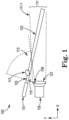
- Figure 1 illustrates a system 100 for detecting smoke 117 in accordance with an embodiment of the present disclosure.
- the system 100 may include a light emitter 101 configured to emit a beam 103.
- the light emitter 101 may be a laser emitter, and the beam 103 may be a laser beam.
- the light emitter 101 may be a photodiode or a laser diode.
- the beam 103 is illustrated in Figure 1 as a single beam of light, in some embodiments, the light emitter 101 may emit pulses of light.
- the light emitter 101 may emit a beam 103 at a particular time interval.
- the beam 103 may illuminate smoke 117.
- the smoke 117 e.g., the presence of the smoke
- the light receiver 105 may be configured to receive reflected light as a result of the beam 103 encountering an object, substance, or material (e.g., smoke 117).
- the light receiver 105 may be, for example, a LiDAR receiver (e.g., a LiDAR sensor).
- the system 100 may also include a processor configured to detect smoke based on light received through the light receiver 105. For instance, the processor may determine whether reflected light indicates the presence of smoke. The processor may do so, for example, by measuring and analyzing the intensity of reflected light received by the receiver 105. If the intensity of the reflected light is below a certain level, the processor may determine that smoke 117 is present. For example, the processor may compare the intensity level of the reflected light to that which would be expected for light reflected against a wall or another hard object; if the comparison indicates the intensity level of the reflected light is less than the expected intensity, the processor can determine that smoke 117 is present.
- a processor configured to detect smoke based on light received through the light receiver 105. For instance, the processor may determine whether reflected light indicates the presence of smoke. The processor may do so, for example, by measuring and analyzing the intensity of reflected light received by the receiver 105. If the intensity of the reflected light is below a certain level, the processor may determine that smoke 117 is present. For example,
- the processor may also determine the location of the smoke 117.
- the processor may be able to determine the location (e.g., the exact location) of the smoke 117 with respect to the light receiver 105 by measuring the amount of time between when the laser beam 103 pulse was emitted and when the reflected light was received by the light receiver 105.
- the processor may also be configured to then take an action in response to detecting smoke.
- the processor upon detecting smoke, may be configured to transmit a signal to a cloud, control panel, central monitoring system, user, or other device of a fire control system indicating the smoke has been detected.
- the processor may also be configured to transmit data, such as motion of the emitter 101 and/or location of the smoke 117, to any of the foregoing examples. Data may be transmitted from the processor with a unique identifier for the environment (e.g., a room) in which the system 100 is located.
- the processor may have embedded software for analyzing and transmitting data and/or for detecting smoke 117.
- the light receiver may include a first (e.g., primary) receiver lens 107 and a second (e.g., secondary) receiver lens 109.
- the primary receiver lens 107 and the secondary receiver lens 109 may be, for example, Fresnel lenses.
- the sizes of lenses 107 and 109 may be proportional to the size of the area to be monitored for smoke (e.g., the larger the area to be monitored for smoke, the greater the sizes of lenses 107 and 109).
- the secondary receiver lens 109 may be designed to collect light reflected from smoke 117 that is much closer to detector system 100 than light reflected from smoke that is further away from detector system 100 and within the field of view of the primary receiver lens 107. Accordingly, the secondary receiver lens 109 may be significantly smaller in size than the primary receiver lens 107.
- the primary receiver lens 107 may be a Fresnel lens of, for example, 90-110 mm in diameter.
- One or both receiver lenses 107 and 109 may be molded from clear plastic.
- the receiver lenses 107 and 109 may be disc-shaped with multiple concentric, grooved rings. This may allow the receiver lenses 107 and 109 to collect light and direct it to a photo-sensitive element within the light receiver 105.
- the secondary receiver lens 109 may be constructed by molding a small part of the primary receiver lens 107 at an angle to the remainder of the receiver lens 107. This would effectively make the secondary lens 109 a smaller lens within the primary receiver lens 107.
- the light emitter 101 and the light receiver 105 may be non-coaxial.
- light emitter 101 may be positioned at an angle with respect to light receiver 105, and the laser beam 103 emitted by light emitter 101 and the fields of view 111 and 113 of the primary and secondary receiver lenses 107 and 109, respectively, may not be parallel, as illustrated in Figure 1 .
- the field of view 111 of the primary receiver lens 107 may include at least a portion of the beam 103 (e.g., field of view 111 partially overlaps the beam 103), a portion of beam 103 may be outside field of view 111 but not outside field of view 113, such that the beam 103 may also illuminate smoke 117 that is positioned outside of the field of view 111 of the primary receiver lens 107, but is not outside the field of view 113 of secondary receiver lens 109.
- the secondary receiver lens 109 may be attached to the primary receiver lens 107.
- the secondary receiver lens 109 may be molded within the primary receiver lens 107.
- the secondary receiver lens 109 may be positioned at an angle with respect to the primary receiver lens 107.
- the field of view 111 of the primary receiver lens 107 may differ from the field of view 113 of the secondary receiver lens. Accordingly, the secondary receiver lens 109 may expand an overall field of view of the light receiver 105.
- the field of view 113 of the secondary receiver lens 109 may at least partially overlap with the field of view 111 of the primary receiver lens 107.
- the field of view 113 of the secondary receiver lens 109 may include at least a portion of the beam 103.
- field of view 112 may include portions of the beam 103 that may not be within the field of view 111 of the primary receiver lens 107.
- the field of view 113 of the secondary receiver lens 109 may include (e.g., cover) a region 115 between an edge 111-1 of the field of view 111 of the primary receiver lens 107 and light emitter 101.
- the edge 111-1 may be between the laser beam 103 and the second receiver lens 109. Accordingly, the combined fields of view 111 and 113 of the primary and secondary receiver lenses, respectively, may capture the entire, or nearly the entire, beam 103.
- the angle at which the primary receiver lens 107 is positioned with respect to the secondary receiver lens 109 may correspond to how much of beam 103 can be captured. This angle may be determined based on, for example, a distance between the emitter 101 and the receiver 105, an angle of the beam 103 with respect to the field of view 111 of the primary receiver lens 107, and/or an angle of the field of view 113 (e.g., angle of view) of the secondary receiver lens 109.
- the system 100 may include a rotation device configured to rotate the light emitter 101.
- the rotation device may be mechanical or electrical. It may be configured to rotate the light emitter 101 at a given speed and/or over a given range. For example, if the system 100 is set up in the corner of a room, the rotation device may rotate the light emitter 101 from 0 degrees to 90 degrees. If the emitter 101 emits pulses such as beam 103 periodically as the rotation device moves, the system 100 may be able to scan an entire room or region for smoke such as smoke 117. The rotation device may rotate the receiver 105 and the light emitter 101 together.
- Figure 2 illustrates a system 200 for detecting smoke in accordance with an embodiment of the present disclosure.
- Some portions and/or elements of smoke detection system 200 can be analogous to smoke detection system 100 as shown and described in connection with Figure 1 .
- field of view 211, and field of view edge 211-1, of primary receiver lens 207 can be analogous to field of view 111, and filed of view edge 111-1, respectively, of primary receiver lens 107 previously described in connection with Figure 1 .
- smoke detection system 200 may include multiple light emitters 201-1 and 201-2, wherein each light emitter 201-1 and 201-2 emits a different beam (laser beams 203-1 and 203-2, respectively).
- Each light emitter 201-1 and 201-2 may be positioned on an opposite side of light receiver 205, wherein the light receiver 205 is configured to receive light reflected by the beams 203-1 and 203-2 off of objects, substances, and materials, such as smoke 217-1 and 217-2.
- the light receiver 205 of the smoke detection system 200 can include a primary receiver lens 207 and a number of secondary receiver lenses 209-1 and 209-2.
- Secondary receiver lens 209-2 can ensure that smoke, such as smoke 217-2, can still be detected, even if it is outside of the fields of view 211 and 213-1 of the primary receiver lens 207 and other secondary receiver lens 203-1, and the emitter 201-2 can be non-coaxial with the light receiver 205.
- the emitter 201-2 can be positioned outside of the region 215 between the first edge 211-1 of the field of view 211 of the primary receiver lens and emitter 201-1.
- the field of view 213-2 of the emitter 201-2 can include at least a portion of the beam 203-2 emitted by the emitter 201-2.
- the field of view 211 of receiver lens 207 may include at least a portion of the beam 203-2.
- Secondary receiver lens 209-2 can have a field of view 213-2 which includes a region 221 between an edge 211-2 of the field of view 211 of the primary receiver lens 207 and the emitter 201-2. This can allow additional smoke, such as smoke 217-2, that is located outside the field of view 211 of the primary receiver lens 207 and the field of view 213-1 of the other secondary receiver lens 209-1 to be detected.
- FIG 3 illustrates a system 300 for detecting smoke in accordance with an embodiment of the present disclosure.
- System 300 may include a light emitter 301 which is configured to emit a beam 303 and positioned vertically above or below a light receiver 305.
- the beam 303 may illuminate smoke 317.
- all of or a portion of the beam 303 may be outside of the field of view of the light receiver 305 (e.g., field of view 111 shown in Figure 1 and field of view 211 shown in Figure 2 ).
- the light receiver may include a first receiver lens 307 and a second receiver lens 309.
- the second receiver lens 309 may be positioned at an angle with respect to the primary receiver lens 307 such that the field of view 313 of the second receiver lens overlaps with portions of the beam 303 that do not overlap with the field of view of the first receiver lens 307.
- FIG 4 illustrates a method 400 for detecting smoke (e.g., smoke 217-1 and 217-2 in Figure 2 and/or 117 in Figure 1 ) in accordance with an embodiment of the present disclosure.
- method 400 may include emitting a laser beam (e.g., beam 103 and/or 203 of Figures 1 and 2 , respectively) from a laser beam emitter (e.g., emitters 101 and/or 201-1 and 201-2 of Figures 1 and 2 , respectively).
- the beam can be emitted while rotating the laser beam emitter.
- the laser beam emitter may be rotated with a range of motion appropriate to scan an entire room for smoke, based on the positioning of the laser beam emitter within that room. This may include, for example, rotating the emitter between 0 and 90 degrees, between 90 and 180 degrees, or between 0 and 180 degrees.
- method 400 may include positioning a light receiver (e.g., light receivers 105 and/or 205 of Figures 1 and 2 , respectively) such that the light receiver is non-coaxial with the path of the laser beam.
- the light receiver may comprise a primary receiver lens (e.g., lens 107 and 207) and a secondary receiver lens (e.g., lens 109, 209-1, and 209-2), as previously described herein.
- the field of view (e.g., field of view 111 and 211) of the primary receiver lens may include at least a portion of the laser beam, as previously described herein.
- the field of view (e.g., field of view 113, 213-1, and 213-2) of the secondary receiver lens may also include another portion of the laser beam, and a region (e.g., regions 115, 215 and 221) between an edge (e.g., edge 111-1, 211-1, and 211-2) of the field of view of the primary receiver lens and the laser emitter, as previously described herein.
- method 400 may include illuminating smoke via the laser beam. This illumination may occur when the path of the laser beam intersects with the smoke.
- method 400 may include detecting the smoke via light reflected from the smoke to the light receiver.
- the light may be received by the light receiver via the primary receiver lens and/or the secondary receiver lens.
- at least a portion of the smoke may be positioned within the field of view of the secondary receiver lens.
- the smoke may be detected by measuring the intensity of the light received by the light receiver and comparing that intensity to an expected intensity for smoke, as previously described herein. If smoke is detected, the method can also include transmitting a signal indicating the presence of the smoke to at least one of another device within a fire control system, a fire control panel, a central monitoring station, a cloud, or a user, as previously described herein.
Landscapes
- Physics & Mathematics (AREA)
- General Physics & Mathematics (AREA)
- Engineering & Computer Science (AREA)
- Chemical & Material Sciences (AREA)
- Analytical Chemistry (AREA)
- Business, Economics & Management (AREA)
- Emergency Management (AREA)
- Radar, Positioning & Navigation (AREA)
- Computer Networks & Wireless Communication (AREA)
- Remote Sensing (AREA)
- Health & Medical Sciences (AREA)
- Life Sciences & Earth Sciences (AREA)
- Biochemistry (AREA)
- General Health & Medical Sciences (AREA)
- Immunology (AREA)
- Pathology (AREA)
- Fire-Detection Mechanisms (AREA)
Applications Claiming Priority (1)
| Application Number | Priority Date | Filing Date | Title |
|---|---|---|---|
| US17/513,102 US12039848B2 (en) | 2021-10-28 | 2021-10-28 | Non-coaxial systems, methods, and devices for detecting smoke |
Publications (1)
| Publication Number | Publication Date |
|---|---|
| EP4174809A1 true EP4174809A1 (de) | 2023-05-03 |
Family
ID=83691223
Family Applications (1)
| Application Number | Title | Priority Date | Filing Date |
|---|---|---|---|
| EP22201046.4A Pending EP4174809A1 (de) | 2021-10-28 | 2022-10-12 | Nichtkoaxiale systeme, verfahren und vorrichtungen zur erkennung von rauch |
Country Status (3)
| Country | Link |
|---|---|
| US (2) | US12039848B2 (de) |
| EP (1) | EP4174809A1 (de) |
| CN (1) | CN116046725A (de) |
Citations (3)
| Publication number | Priority date | Publication date | Assignee | Title |
|---|---|---|---|---|
| US8422000B2 (en) * | 2002-10-10 | 2013-04-16 | Qinetiq Limited | Bistatic laser radar apparatus |
| US20190383729A1 (en) * | 2018-06-15 | 2019-12-19 | Kidde Technologies, Inc. | Optically enhanced protective cover for chamberless point sensor |
| WO2020064935A1 (de) * | 2018-09-28 | 2020-04-02 | Siemens Schweiz Ag | Streulichtrauchmelder mit einer zweifarben-led, einem photosensor und einem dem photosensor vorgeschalteten oder der zweifarben-led nachgeschalteten wellenlängenselektiven polarisator sowie geeignete verwendung eines solchen polarisators |
Family Cites Families (73)
| Publication number | Priority date | Publication date | Assignee | Title |
|---|---|---|---|---|
| US4121110A (en) * | 1976-11-04 | 1978-10-17 | Solomon Elias E | Optically biased smoke detector |
| SE458480B (sv) | 1986-12-11 | 1989-04-03 | Bofors Ab | Anordning i zonroer foer uppskjutbar enhet, innefattande saendare och mottagare foer optisk straalning |
| DE3831654A1 (de) * | 1988-09-17 | 1990-03-22 | Hartwig Beyersdorf | Optischer rauchmelder |
| GB2274333B (en) * | 1993-01-07 | 1996-12-11 | Hochiki Co | Smoke detecting apparatus capable of detecting both smoke and fine particles |
| US7421321B2 (en) * | 1995-06-07 | 2008-09-02 | Automotive Technologies International, Inc. | System for obtaining vehicular information |
| US5719557A (en) * | 1994-05-19 | 1998-02-17 | Digital Security Controls Ltd. | Photoelectric smoke detector |
| US5764142A (en) * | 1995-09-01 | 1998-06-09 | Pittway Corporation | Fire alarm system with smoke particle discrimination |
| US6181251B1 (en) * | 1997-10-28 | 2001-01-30 | Robert R. Kelly | Combination smoke detection device and laser escape indicator |
| DE19902319B4 (de) * | 1999-01-21 | 2011-06-30 | Novar GmbH, Albstadt-Ebingen Zweigniederlassung Neuss, 41469 | Streulichtbrandmelder |
| US6876305B2 (en) * | 1999-12-08 | 2005-04-05 | Gentex Corporation | Compact particle sensor |
| US6225910B1 (en) * | 1999-12-08 | 2001-05-01 | Gentex Corporation | Smoke detector |
| GB2370903A (en) * | 2001-01-08 | 2002-07-10 | Thorn Security | A fire detector |
| PT102617B (pt) | 2001-05-30 | 2004-01-30 | Inst Superior Tecnico | Sistema lidar controlado por computador para localizacao de fumo, aplicavel, em particular, a deteccao precoce de incendios florestais |
| DE10246056A1 (de) * | 2002-10-02 | 2004-04-22 | Robert Bosch Gmbh | Rauchmelder |
| US7576659B2 (en) * | 2006-06-07 | 2009-08-18 | L.I.F.E. Support Technologies, Llc | Smoke detection and laser escape indication system utilizing base and satellite |
| US7592923B2 (en) * | 2006-06-07 | 2009-09-22 | L.I.F.E. Support Technologies, Llc | Smoke detection and laser escape indication system utilizing a control master with base and satellite stations |
| US7476862B2 (en) * | 2007-01-22 | 2009-01-13 | Brunswick Corporation | Method for detecting a source of heat near a marine vessel |
| CA2993208C (en) | 2007-11-15 | 2021-01-26 | Garrett Thermal Systems Limited | Particle detection |
| US20090292213A1 (en) * | 2008-05-21 | 2009-11-26 | Searete Llc, A Limited Liability Corporation Of The State Of Delaware | Circulatory monitoring systems and methods |
| DK2093734T3 (da) | 2008-02-19 | 2011-10-10 | Siemens Ag | Røgalarm med tidslig fortolkning af et tilbagekoblingssignal, testfremgangsmåde til funktionsdygtighed af en røgalarm |
| US20100073172A1 (en) * | 2008-09-25 | 2010-03-25 | L.I.F.E. Support Technologies, Llc | Dual condition fire/smoke detector with adjustable led cannon |
| US20100194574A1 (en) | 2009-01-30 | 2010-08-05 | David James Monk | Particle detection system and method of detecting particles |
| WO2010124347A1 (en) * | 2009-05-01 | 2010-11-04 | Xtralis Technologies Ltd | Improvements to particle detectors |
| US8638436B2 (en) * | 2009-09-15 | 2014-01-28 | Hochiki Corporation | Smoke sensor |
| US9322646B2 (en) | 2010-04-09 | 2016-04-26 | The Trustees Of The Stevens Institute Of Technology | Adaptive mechanism control and scanner positioning for improved three-dimensional laser scanning |
| FR2970102B1 (fr) * | 2010-12-31 | 2012-12-28 | Jacques Lewiner | Detecteur de fumee |
| JP6029055B2 (ja) * | 2011-10-24 | 2016-11-24 | パナソニックIpマネジメント株式会社 | 煙感知器 |
| EP2608174B1 (de) | 2011-12-20 | 2016-10-19 | Siemens Schweiz AG | Verfahren zur Erkennung eines Störobjektes in einem Streuvolumen eines optischen Brandmelders und optischer Brandmelder |
| GB2499256A (en) * | 2012-02-13 | 2013-08-14 | Thorn Security | Fire detector sensing photo-luminescent emissions from illuminated particles |
| US9140646B2 (en) * | 2012-04-29 | 2015-09-22 | Valor Fire Safety, Llc | Smoke detector with external sampling volume using two different wavelengths and ambient light detection for measurement correction |
| US8952821B2 (en) * | 2012-04-29 | 2015-02-10 | Valor Fire Safety, Llc | Smoke detector utilizing ambient-light sensor, external sampling volume, and internally reflected light |
| WO2014043461A1 (en) | 2012-09-14 | 2014-03-20 | Faro Technologies, Inc. | Laser scanner with dynamical adjustment of angular scan velocity |
| DE102013101280B4 (de) * | 2013-02-08 | 2025-02-20 | Schako Kg | Rauchmelder |
| EP2775464B1 (de) * | 2013-03-06 | 2018-01-17 | Siemens Schweiz AG | Gefahrenmelder mit einem kontaktlos arbeitenden Wärmestrahlungssensor zur Ermittlung einer Umgebungstemperatur |
| KR20160079057A (ko) * | 2013-10-30 | 2016-07-05 | 발로르 파이어 세이프티, 엘엘씨 | 외부 샘플링 볼륨 및 주변광 배제를 갖는 연기 감지기 |
| US10115280B2 (en) * | 2014-06-26 | 2018-10-30 | Life Safety Distribution Ag | Detector with optical block |
| EP3029646B1 (de) * | 2014-12-01 | 2019-01-30 | Siemens Schweiz AG | Streulichtrauchmelder mit einer zweifarbigen Leuchtdiode |
| EP3091517B1 (de) * | 2015-05-06 | 2017-06-28 | Siemens Schweiz AG | Offener streulichtrauchmelder sowie prüfgerät für einen derartigen offenen streulichtrauchmelder |
| GB2543065A (en) * | 2015-10-06 | 2017-04-12 | Thorn Security | Smoke detector tester |
| US9824564B2 (en) * | 2015-12-14 | 2017-11-21 | Honeywell International Inc. | Aspirated smoke detector with improved optical chamber |
| CN108883575A (zh) * | 2016-02-18 | 2018-11-23 | 维洛3D公司 | 准确的三维打印 |
| US20220379381A1 (en) * | 2016-02-18 | 2022-12-01 | Velo3D, Inc. | Accurate three-dimensional printing |
| US10871452B2 (en) * | 2016-06-15 | 2020-12-22 | Kidde Technologies, Inc. | Systems and methods for chamberless smoke detection and indoor air quality monitoring |
| WO2018027104A1 (en) * | 2016-08-04 | 2018-02-08 | Carrier Corporation | Smoke detector |
| WO2018044958A1 (en) | 2016-08-29 | 2018-03-08 | Okeeffe James | Laser range finder with smart safety-conscious laser intensity |
| US10379540B2 (en) | 2016-10-17 | 2019-08-13 | Waymo Llc | Light detection and ranging (LIDAR) device having multiple receivers |
| US11860292B2 (en) * | 2016-11-17 | 2024-01-02 | Trinamix Gmbh | Detector and methods for authenticating at least one object |
| EP3276680A1 (de) * | 2017-01-25 | 2018-01-31 | Siemens Schweiz AG | Optische rauchdetektion nach dem zweifarben-prinzip mittels einer leuchtdiode mit einem led-chip zur lichtemission und mit einem lichtkonverter zum umwandeln eines teils des emittierten lichts in langwelligeres licht |
| US10467509B2 (en) * | 2017-02-14 | 2019-11-05 | Microsoft Technology Licensing, Llc | Computationally-efficient human-identifying smart assistant computer |
| US10545240B2 (en) | 2017-03-28 | 2020-01-28 | Luminar Technologies, Inc. | LIDAR transmitter and detector system using pulse encoding to reduce range ambiguity |
| US10019891B1 (en) * | 2017-03-29 | 2018-07-10 | Google Llc | Smoke detector for distinguishing between an alarm condition and a nuisance condition |
| CN107132519A (zh) * | 2017-06-30 | 2017-09-05 | 深圳市镭神智能系统有限公司 | 一种激光雷达光路系统 |
| EP3454311B1 (de) * | 2017-09-08 | 2020-06-10 | Tyco Fire & Security GmbH | Kammerloser rauchmelder |
| KR102182719B1 (ko) | 2018-03-29 | 2020-11-24 | 주식회사 에스오에스랩 | 라이다 스캐닝 장치 |
| US10578720B2 (en) * | 2018-04-05 | 2020-03-03 | Luminar Technologies, Inc. | Lidar system with a polygon mirror and a noise-reducing feature |
| FR3080480B1 (fr) * | 2018-04-19 | 2022-10-07 | Shokly | Detecteur optique de fumee a rayonnement diffuse |
| US11184967B2 (en) * | 2018-05-07 | 2021-11-23 | Zane Coleman | Angularly varying light emitting device with an imager |
| EP3791162B1 (de) * | 2018-05-11 | 2025-06-25 | Carrier Corporation | Mehrpunkt-erfassungssystem |
| EP3762909A1 (de) * | 2018-05-28 | 2021-01-13 | Greenwave Systems PTE. LTD. | Bereichsüberwachung und kommunikation |
| US10670719B2 (en) | 2018-05-31 | 2020-06-02 | Beijing Voyager Technology Co., Ltd. | Light detection system having multiple lens-receiver units |
| DE102018214209A1 (de) | 2018-08-22 | 2020-02-27 | Robert Bosch Gmbh | Augensicheres LIDAR-System mit einstellbarem Abtastbereich |
| CN112997099A (zh) * | 2018-11-13 | 2021-06-18 | 纽诺有限公司 | 用于车辆盲点检测的光检测与测距 |
| US11269065B2 (en) | 2018-11-19 | 2022-03-08 | Infineon Technologies Ag | Muilti-detector with interleaved photodetector arrays and analog readout circuits for lidar receiver |
| WO2021019308A1 (en) | 2019-04-25 | 2021-02-04 | Innoviz Technologies Ltd. | Flash lidar having nonuniform light modulation |
| US11150348B2 (en) * | 2019-10-02 | 2021-10-19 | Cepton Technologies, Inc. | Techniques for detecting cross-talk interferences in lidar imaging sensors |
| WO2021083016A1 (zh) * | 2019-11-01 | 2021-05-06 | 上海禾赛科技股份有限公司 | 激光雷达和利用其进行探测的方法 |
| US11474018B2 (en) * | 2019-12-05 | 2022-10-18 | Carrier Corporation | Fluorescence enhanced LIDAR based particulate detector |
| US11657692B1 (en) * | 2021-10-28 | 2023-05-23 | Honeywell International Inc. | Smoke detector |
| CA3180627C (en) * | 2021-11-01 | 2026-03-03 | Michael Griffiths | Laser device and system |
| US20230191490A1 (en) * | 2021-12-17 | 2023-06-22 | Velo3D, Inc. | Accurate additive manufacturing |
| CN116577250A (zh) * | 2022-02-08 | 2023-08-11 | 开利公司 | 组合烟雾和空气质量检测 |
| CA3245105A1 (en) * | 2022-03-09 | 2023-09-14 | Axon4D Corp. | APPARATUS AND METHODS FOR MONITORING A FLOATING ROOF TANK |
| KR20240113138A (ko) * | 2023-01-13 | 2024-07-22 | 한국전자통신연구원 | 비화재보 방지 기능을 갖는 조기 화재 감지 장치 및 방법 |
-
2021
- 2021-10-28 US US17/513,102 patent/US12039848B2/en active Active
-
2022
- 2022-10-12 EP EP22201046.4A patent/EP4174809A1/de active Pending
- 2022-10-20 CN CN202211289002.8A patent/CN116046725A/zh active Pending
-
2024
- 2024-07-16 US US18/774,164 patent/US20240371247A1/en active Pending
Patent Citations (4)
| Publication number | Priority date | Publication date | Assignee | Title |
|---|---|---|---|---|
| US8422000B2 (en) * | 2002-10-10 | 2013-04-16 | Qinetiq Limited | Bistatic laser radar apparatus |
| US20190383729A1 (en) * | 2018-06-15 | 2019-12-19 | Kidde Technologies, Inc. | Optically enhanced protective cover for chamberless point sensor |
| US10677714B2 (en) * | 2018-06-15 | 2020-06-09 | Kidde Technologies, Inc. | Optically enhanced protective cover for chamberless point sensor |
| WO2020064935A1 (de) * | 2018-09-28 | 2020-04-02 | Siemens Schweiz Ag | Streulichtrauchmelder mit einer zweifarben-led, einem photosensor und einem dem photosensor vorgeschalteten oder der zweifarben-led nachgeschalteten wellenlängenselektiven polarisator sowie geeignete verwendung eines solchen polarisators |
Also Published As
| Publication number | Publication date |
|---|---|
| US12039848B2 (en) | 2024-07-16 |
| CN116046725A (zh) | 2023-05-02 |
| US20230138573A1 (en) | 2023-05-04 |
| US20240371247A1 (en) | 2024-11-07 |
Similar Documents
| Publication | Publication Date | Title |
|---|---|---|
| US20200056973A1 (en) | Particle detection | |
| US20080297360A1 (en) | Particle Detector, System and Method | |
| US12125356B2 (en) | Smoke detector | |
| CN213813949U (zh) | 一种激光雷达 | |
| EP4174809A1 (de) | Nichtkoaxiale systeme, verfahren und vorrichtungen zur erkennung von rauch | |
| US20230162583A1 (en) | Operating a scanning smoke detector | |
| US10620337B2 (en) | Retro-reflective sensor with multiple detectors | |
| US3147384A (en) | Flash detection and location system | |
| EP3364229B1 (de) | Optische abtastvorrichtung zur erkennung von objekten | |
| JP2019105550A (ja) | 物体検出装置、物体検出装置の制御方法、および物体検出装置の制御プログラム | |
| AU2018282480A1 (en) | Particle detection | |
| WO2017195754A1 (ja) | 監視システム | |
| KR101029712B1 (ko) | 반사판의 평형 조절을 위한 레이저 발광 수단을 구비한 광전식 분리형 연기 감지 시스템 | |
| US12620294B2 (en) | Sensing system for fire event detection | |
| EP0204436A1 (de) | Gerät zur Lichtverteilung und -abtastung | |
| CN220019871U (zh) | 一种激光雷达测距链路的整体监测结构及激光雷达 | |
| GB2269665A (en) | Optical beam smoke sensor | |
| CN216792445U (zh) | 用于前窗监控的光电传感器 | |
| US20250006031A1 (en) | Sensing system for fire event detection | |
| TW201925823A (zh) | 距離感測器 | |
| CN2771875Y (zh) | 自动测定两个物体间相对方向的系统 | |
| JP2006350908A (ja) | 光学式情報入力装置 | |
| CN119846605A (zh) | 用于检测LiDAR传感器的窗口污染的装置及方法 | |
| UA146281U (uk) | Система виявлення електронних пристроїв, що проводять фото- або відеозйомку | |
| JPWO2017195755A1 (ja) | 監視システム |
Legal Events
| Date | Code | Title | Description |
|---|---|---|---|
| PUAI | Public reference made under article 153(3) epc to a published international application that has entered the european phase |
Free format text: ORIGINAL CODE: 0009012 |
|
| STAA | Information on the status of an ep patent application or granted ep patent |
Free format text: STATUS: REQUEST FOR EXAMINATION WAS MADE |
|
| 17P | Request for examination filed |
Effective date: 20221012 |
|
| AK | Designated contracting states |
Kind code of ref document: A1 Designated state(s): AL AT BE BG CH CY CZ DE DK EE ES FI FR GB GR HR HU IE IS IT LI LT LU LV MC ME MK MT NL NO PL PT RO RS SE SI SK SM TR |
|
| STAA | Information on the status of an ep patent application or granted ep patent |
Free format text: STATUS: EXAMINATION IS IN PROGRESS |
|
| 17Q | First examination report despatched |
Effective date: 20240523 |