EP4174821A1 - Systèmes et procédés de surveillance et de fourniture d'alertes pour intersections de pistes de décollage - Google Patents
Systèmes et procédés de surveillance et de fourniture d'alertes pour intersections de pistes de décollage Download PDFInfo
- Publication number
- EP4174821A1 EP4174821A1 EP22201122.3A EP22201122A EP4174821A1 EP 4174821 A1 EP4174821 A1 EP 4174821A1 EP 22201122 A EP22201122 A EP 22201122A EP 4174821 A1 EP4174821 A1 EP 4174821A1
- Authority
- EP
- European Patent Office
- Prior art keywords
- runway
- takeoff
- intersection
- length
- aircraft
- Prior art date
- Legal status (The legal status is an assumption and is not a legal conclusion. Google has not performed a legal analysis and makes no representation as to the accuracy of the status listed.)
- Granted
Links
Images


Classifications
-
- G—PHYSICS
- G08—SIGNALLING
- G08G—TRAFFIC CONTROL SYSTEMS
- G08G5/00—Traffic control systems for aircraft
- G08G5/50—Navigation or guidance aids
- G08G5/52—Navigation or guidance aids for take-off
-
- G—PHYSICS
- G01—MEASURING; TESTING
- G01C—MEASURING DISTANCES, LEVELS OR BEARINGS; SURVEYING; NAVIGATION; GYROSCOPIC INSTRUMENTS; PHOTOGRAMMETRY OR VIDEOGRAMMETRY
- G01C23/00—Combined instruments indicating more than one navigational value, e.g. for aircraft; Combined measuring devices for measuring two or more variables of movement, e.g. distance, speed or acceleration
- G01C23/005—Flight directors
-
- G—PHYSICS
- G08—SIGNALLING
- G08G—TRAFFIC CONTROL SYSTEMS
- G08G5/00—Traffic control systems for aircraft
- G08G5/20—Arrangements for acquiring, generating, sharing or displaying traffic information
- G08G5/21—Arrangements for acquiring, generating, sharing or displaying traffic information located onboard the aircraft
-
- G—PHYSICS
- G08—SIGNALLING
- G08G—TRAFFIC CONTROL SYSTEMS
- G08G5/00—Traffic control systems for aircraft
- G08G5/20—Arrangements for acquiring, generating, sharing or displaying traffic information
- G08G5/26—Transmission of traffic-related information between aircraft and ground stations
-
- G—PHYSICS
- G08—SIGNALLING
- G08G—TRAFFIC CONTROL SYSTEMS
- G08G5/00—Traffic control systems for aircraft
- G08G5/50—Navigation or guidance aids
- G08G5/51—Navigation or guidance aids for control when on the ground, e.g. taxiing or rolling
-
- G—PHYSICS
- G08—SIGNALLING
- G08G—TRAFFIC CONTROL SYSTEMS
- G08G5/00—Traffic control systems for aircraft
- G08G5/70—Arrangements for monitoring traffic-related situations or conditions
- G08G5/76—Arrangements for monitoring traffic-related situations or conditions for monitoring atmospheric conditions
-
- G—PHYSICS
- G08—SIGNALLING
- G08G—TRAFFIC CONTROL SYSTEMS
- G08G5/00—Traffic control systems for aircraft
- G08G5/50—Navigation or guidance aids
- G08G5/55—Navigation or guidance aids for a single aircraft
Definitions
- Embodiments of the subject matter described herein relate generally to aircraft systems. More particularly, embodiments of the subject matter relate to systems and methods for assisting with identifying valid runway intersections for takeoff at an aerodrome.
- An aircraft may begin takeoff from a beginning point on a runway and use the full-length of the runway for takeoff. In some situations, an aircraft may begin takeoff from an intersection takeoff position on the runway and begin takeoff from the intersection takeoff position and only use part of the length of the runway for takeoff.
- An intersection takeoff is a takeoff that starts at a position different from the beginning of a runway. When an intersection takeoff is undertaken, some of the runway will not be available for the takeoff.
- An aircraft may be cleared by an air traffic controller (ATC) to depart from a published intersection take off position upon request by a pilot, or when initiated by ATC upon acceptance by the pilot.
- ATC air traffic controller
- Takeoff from an intersection take off position can be safe when certain conditions are met. For example, on high temperature days (e.g., about 47 degrees Celsius) a longer runway for takeoff is required since the air is thinner. Those conditions may include the time of day, visibility, specific intersection location, temperature, and others.
- intersection takeoff The choice between a full-length takeoff or an intersection take off is an aspect of the decision making process for the flight crew. While ATC may offer (or approve) an intersection takeoff it is the responsibility of the pilot in command to assess whether this is a safe option and, if not, to decline the ATC proposal.
- the potential benefits (e.g., flight efficiency) of an intersection takeoff needs to be balanced against the potential risks. This can add to pilot workload during this phase of operations.
- a flight deck system for identifying valid runway intersections for takeoff includes an aircraft display device in an aircraft and a controller.
- the controller is configured to: estimate a runway length required for takeoff based on aircraft parameters (e.g., aircraft type, aircraft weight, etc.); estimate, at each of a plurality of runway intersections, a corrected runway length at the runway intersection by applying an elevation correction, a temperature correction, and a gradient correction; determine, based on the estimated runway length required for takeoff and the corrected runway length at each of the plurality of runway intersections, each valid runway intersection from the plurality of runway intersections whose corrected runway length is long enough for use by the aircraft for takeoff and each invalid runway intersection from the plurality of runway intersections whose corrected runway length is not long enough for use by the aircraft for takeoff; and signal the aircraft display device to display on a map depicting the takeoff runway an invalid intersection icon adjacent to each invalid runway intersection.
- a method in a flight deck system in an aircraft for identifying valid runway intersections for takeoff includes: estimating a runway length required for takeoff based on aircraft parameters (e.g., aircraft type, aircraft weight, etc.); estimating, at each of a plurality of runway intersections, a corrected runway length at the runway intersection by applying an elevation correction, a temperature correction, and a gradient correction; determining, based on the estimated runway length required for takeoff and the corrected runway length at each of the plurality of runway intersections, each valid runway intersection from the plurality of runway intersections whose corrected runway length is long enough for use by the aircraft for takeoff and each invalid runway intersection from the plurality of runway intersections whose corrected runway length is not long enough for use by the aircraft for takeoff; and signaling an aircraft display device to display on a map depicting the takeoff runway an invalid intersection icon adjacent to each invalid runway intersection.
- aircraft parameters e.g., aircraft type, aircraft weight, etc.
- a non-transitory computer readable medium encoded with instructions configurable to cause a controller in an aircraft to perform a method for identifying valid runway intersections includes: estimating a runway length required for takeoff based on aircraft parameters (e.g., aircraft type, aircraft weight, etc.); estimating, at each of a plurality of runway intersections, a corrected runway length at the runway intersection by applying an elevation correction, a temperature correction, and a gradient correction; determining, based on the estimated runway length required for takeoff and the corrected runway length at each of the plurality of runway intersections, each valid runway intersection from the plurality of runway intersections whose corrected runway length is long enough for use by the aircraft for takeoff and each invalid runway intersection from the plurality of runway intersections whose corrected runway length is not long enough for use by the aircraft for takeoff; and signaling an aircraft display device to display on a map depicting the takeoff runway an invalid intersection icon adjacent to each invalid runway intersection.
- aircraft parameters e.g., aircraft type, aircraft weight, etc.
- module refers to any hardware, software, firmware, electronic control component, processing logic, and/or processor device, individually or in any combination, including without limitation: application specific integrated circuit (ASIC), a field-programmable gate-array (FPGA), an electronic circuit, a processor (shared, dedicated, or group) and memory that executes one or more software or firmware programs, a combinational logic circuit, and/or other suitable components that provide the described functionality.
- ASIC application specific integrated circuit
- FPGA field-programmable gate-array
- processor shared, dedicated, or group
- memory executes one or more software or firmware programs, a combinational logic circuit, and/or other suitable components that provide the described functionality.
- Embodiments of the present disclosure may be described herein in terms of functional and/or logical block components and various processing steps. It should be appreciated that such block components may be realized by any number of hardware, software, and/or firmware components configured to perform the specified functions. For example, an embodiment of the present disclosure may employ various integrated circuit components, e.g., memory elements, digital signal processing elements, logic elements, look-up tables, or the like, which may carry out a variety of functions under the control of one or more microprocessors or other control devices. In addition, those skilled in the art will appreciate that embodiments of the present disclosure may be practiced in conjunction with any number of systems, and that the systems described herein is merely exemplary embodiments of the present disclosure.
- the subject matter described herein discloses apparatus, systems, techniques, and articles for estimating and providing an indication of valid intersections for a selected takeoff runway.
- the apparatus, systems, techniques, and articles provided considers aircraft parameters (e.g., aircraft type, weight, etc.) and current environmental conditions (e.g., airport elevation, temperature, runway gradient, etc.) and makes an estimation based on the considered aircraft parameters and environment conditions.
- the apparatus, systems, techniques, and articles provided herein can estimate corrections to basic runway length when estimating whether an intersection can be used as a takeoff intersection.
- the apparatus, systems, techniques, and articles provided herein can estimate corrections to be applied to basic runway length to determine the actual length of a runway at an aerodrome.
- the apparatus, systems, techniques, and articles provided herein can estimate corrections including an elevation correction, a temperature correction, and a gradient correction.
- the apparatus, systems, techniques, and articles provided herein can consider the runway corrections and aircraft parameters as a proposed taxi path to the takeoff runway is entered, and estimate and cause display valid intersections to be displayed.
- An aircraft can be equipped with a three dimensional (3D) airport moving map (AMM) display function and/or a two dimensional (2D) AMM that can display an intended path for the aircraft to follow for taxiing from a parking area out to the departure runway in preparation for takeoff.
- the apparatus, systems, techniques, and articles provided herein can cause a display on the 3D AMM and/or 2D AMM (or other display) that indicates which runway intersection are suitable and cause the display of available runway length on both sides of the runway at the intersection.
- the apparatus, systems, techniques, and articles provided herein can cause an alert to be provided to flight crew when the takeoff runway is not being displayed to alert the flight crew when an unsuitable runway intersection has been selected.
- the apparatus, systems, techniques, and articles provided herein can provide an alert based on a taxi plan input from ATC/Datalink/Manual fight crew entry.
- the apparatus, systems, techniques, and articles provided herein can compare aircraft parameters with the performance to identify pilot errors to input values (e.g., takeoff weight information, etc.).
- pilot errors e.g., takeoff weight information, etc.
- the apparatus, systems, techniques, and articles provided herein can review the manual inputs to determine if they are correct based on aircraft specific parameters, parameters related to environment and required performance for intersections available.
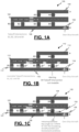
- FIG. 1A is a map depicting an example operating environment 100 at an airport or other aerodrome.
- the example operating environment 100 includes a takeoff runway 102, a taxiway A (104) and a taxiway B (106) on which an aircraft 108 traverses to reach the takeoff runway 102, and a plurality of runway intersections (A3, A4, B1, B2, B3, and B4) for accessing the takeoff runway 102 from the taxiway A (104) and the taxiway B (106).
- the runway intersections B1, B2, B3, and B4 are potential takeoff intersections for the aircraft 108.
- FIG. 1B is a map depicting an example operating environment 110 at an airport or other aerodrome.
- the example operating environment 110 includes a takeoff runway 112, a taxiway A (114) and a taxiway B (116) on which an aircraft 118 traverses to reach the takeoff runway 112, and a plurality of runway intersections (A3, A4, B1, B2, B3, and B4) for accessing the takeoff runway 112 from the taxiway A (114) and the taxiway B (116).
- the runway intersections B1, B2, B3, and B4 are potential takeoff intersections for the aircraft 108.
- runway intersections B1, B2, and B3 are each available as a takeoff intersection for the aircraft 118 and are so indicated by a valid intersection graphical element 117
- runway intersection B4 is not available as a takeoff intersection for the aircraft 118 and is so indicated by an invalid intersection graphical element 119
- the valid intersection graphical element 117 may use various visual features such as color ( e.g., green) to indicate that an associated runway intersection is available as a takeoff intersection.
- the invalid intersection graphical element 119 may use various visual features such as color ( e.g., red) to indicate that an associated runway intersection is not available as a takeoff intersection.
- FIG. 1C is a map depicting an example operating environment 120 at an airport or other aerodrome.
- the example operating environment 120 includes a takeoff runway 122, a taxiway A (124) and a taxiway B (126) on which an aircraft 128 traverses to reach the takeoff runway 122, and a plurality of runway intersections (A3, A4, B1, B2, B3, and B4) for accessing the takeoff runway 122 from the taxiway A (124) and the taxiway B (126).
- the runway intersections B1, B2, B3, and B4 are potential takeoff intersections for the aircraft 108.
- runway intersections B1, B2, and B3 are each available as a takeoff intersection for the aircraft 128 and are so indicated by a valid intersection graphical element 127, and runway intersection B4 is not available as a takeoff intersection for the aircraft 128 and is so indicated by an invalid intersection graphical element 129.
- the runway intersections B1, B2, and B3 are available as takeoff intersections for the aircraft 128 because they each have a corrected runway length that is long enough for use by the aircraft 128 for takeoff, wherein the corrected runway length is equal to a nominal runway length plus an elevation correction, a temperature correction, and a gradient correction, and wherein the nominal runway length is determined based on the actual length of the runway from the runway intersection to the end of the runway.
- the runway intersection B4 is not available as a takeoff intersection for the aircraft 128 because it has a corrected runway length that is not long enough for use by the aircraft 128 for takeoff.
- the valid intersection graphical element 127 may use various visual features such as color ( e.g., green) to indicate that an associated runway intersection is available as a takeoff intersection.
- the invalid intersection graphical element 129 may use various visual features such as color ( e.g., red) to indicate that an associated runway intersection is not available as a takeoff intersection.
- a corrected runway length graphical indicator 131 of a corrected runway length is provided adjacent to the runway intersection B4.
- This corrected runway length graphical indicator 131 provides a corrected runway length.
- the example corrected runway length graphical indicator 131 indicates that the corrected runway length at runway intersection is 7500 meters.
- the corrected runway length graphical indicator 131 is only provided at the runway intersection B4, which is not available as a takeoff intersection, in other examples, the corrected runway length graphical indicator 131 may be provided at all or some of the other runway intersections (A1, A2, B1, B2, B3) including those runway intersections that are available as a takeoff intersection.
- a takeoff direction indicator 133 is provided adjacent to the runway intersection B4. This takeoff direction indicator 133 provides an indication of the direction to the end of the runway. Although, in this example, the takeoff direction indicator 133 is only provided at the runway intersection B4, which is not available as a takeoff intersection, in other examples, the takeoff direction indicator 133 may be provided at all or some of the other runway intersections (A1, A2, B1, B2, B3) including those runway intersections that are available as a takeoff intersection.
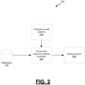
- FIG. 2 is a block diagram depicting an example valid takeoff runway intersection identification system 200.
- the example valid runway intersection identification system 200 includes a valid takeoff runway intersection controller 202 that is configured to identify valid takeoff runway intersections and invalid takeoff runway intersections to a flight crew via a display device 204.
- the example valid takeoff runway intersection controller 202 is configured to receive aircraft parameters (such as aircraft type and aircraft weight) and runway parameter information (such as actual runway length at various runway intersections, runway temperature, runway elevation, runway gradient) via onboard aircraft systems 206 and databases 208.
- aircraft parameters such as aircraft type and aircraft weight
- runway parameter information such as actual runway length at various runway intersections, runway temperature, runway elevation, runway gradient
- the example valid takeoff runway intersection controller 202 is configured to use the aircraft parameters and runway parameter information to estimate a runway length required for takeoff based on the aircraft parameters, estimate a corrected runway length at each of a plurality of runway intersections by applying an elevation correction, a temperature correction, and a gradient ( e.g., runway slope) correction to a nominal runway length for the runway intersection, and determine, based on the estimated runway length required for takeoff and the corrected runway length at each of the plurality of runway intersections, each valid runway intersection from the plurality of runway intersections whose corrected runway length is long enough for use by the aircraft for takeoff and each invalid runway intersection from the plurality of runway intersections whose corrected runway length is not long enough for use by the aircraft for takeoff.
- the example valid takeoff runway intersection controller 202 is further configured to signal the display device 204 to display on a map depicting the takeoff runway at least an invalid intersection icon adjacent to each invalid runway intersection.
- the display device 204 may be a primary flight display (PFD), Navigation display (ND), heads up display (HUD), heads down display (HDD),an electronic flight bag (EFB), a tablet computer, a smartphone, a wearable device, or some other device for displaying messages in an aircraft cockpit.
- PFD primary flight display
- ND Navigation display
- HUD heads up display
- HDD heads down display
- EFB electronic flight bag
- the valid takeoff runway intersection controller 202 includes at least one processor and a computer-readable storage device or media encoded with programming instructions for configuring the controller.
- the processor may be any custom-made or commercially available processor, a central processing unit (CPU), a graphics processing unit (GPU), an application specific integrated circuit (ASIC), a field programmable gate array (FPGA), an auxiliary processor among several processors associated with the controller, a semiconductor-based microprocessor (in the form of a microchip or chip set), any combination thereof, or generally any device for executing instructions.
- the computer readable storage device or media may include volatile and nonvolatile storage in read-only memory (ROM), random-access memory (RAM), and keep-alive memory (KAM), for example.
- KAM is a persistent or non-volatile memory that may be used to store various operating variables while the processor is powered down.
- the computer-readable storage device or media may be implemented using any of a number of known memory devices such as PROMs (programmable read-only memory), EPROMs (electrically PROM), EEPROMs (electrically erasable PROM), flash memory, or any other electric, magnetic, optical, or combination memory devices capable of storing data, some of which represent executable programming instructions, used by the controller.
- the takeoff runway intersection controller 202 is configured to estimate the elevation correction by multiplying a nominal runway length by a first factor, wherein the nominal runway length is determined based on the length of the runway from the runway intersection to the end of the runway.
- the takeoff runway intersection controller 202 is further configured to estimate the temperature correction by multiplying the nominal runway length by a second factor and estimate the gradient correction by multiplying the nominal runway length by a third factor.
- the takeoff runway intersection controller 202 estimates the corrected runway length as equating the corrected runway length to the nominal runway length plus the elevation correction, the temperature correction, and the gradient correction.
- the first factor is based on a first fixed percentage increase per each fixed altitude range increase above sea level at the takeoff runway
- the second factor is based on a second fixed percentage increase per fixed amount of temperature increase at the takeoff runway
- the third factor is based on a third fixed percentage increase per fixed degree of effective gradient when the combined elevation correction and temperature correction remains less than a fourth fixed percentage of the nominal runway length.
- the first factor is seven percent (7%) per 300 meter altitude above mean sea level (MSL)
- the second factor is one percent (1%) for every one-degree Celsius rise in Airport Reference Temperature (ART)
- the third factor is 20 percent (20%) for every one percent of the effective gradient when the combined elevation correction and temperature correction remains less than 35 percent (35%) of the nominal takeoff runway length.
- the example takeoff runway intersection controller 202 is configured to generate a takeoff runway map (e.g., operating environment 100/110/120) that graphically depicts the takeoff runway ( e.g., takeoff runway 102/112/122), a taxiway (e.g., taxiway 106/116/126) on which the aircraft ( e.g., aircraft 108/118/128) traverses to reach the takeoff runway, the runway intersections ( e.g., B1 (107/117/127), B2 (107/117/127), B3 (107/117/127), and B4 (109/119/129)) from the taxiway to the takeoff runway, an aircraft graphical element 108/118/128 representative of the aircraft, a valid intersection graphical element ( e.g., 117/127) for identifying each valid runway intersection and an invalid intersection graphical element ( e.g., 119/129) for identifying each invalid runway intersection.
- the example takeoff runway intersection controller 202 is configured to further configured to signal an aircraft display device ( e
- the takeoff runway intersection controller 202 is further configured to position an indication (e.g., corrected runway length graphical indicator 131) of the corrected runway length for each runway intersection adjacent to the runway intersection.
- the takeoff runway intersection controller 202 is further configured to position a takeoff direction indicator (e.g., takeoff direction indicator 133) for each runway intersection adjacent to the runway intersection.
- the takeoff runway intersection controller 202 is further configured to provide an alert on a cockpit display when the corrected runway length for a runway intersection selected using the cockpit display by a flight crew member is not long enough for use by the aircraft for takeoff.
- FIG. 3 is a diagram depicting an example 3D (three dimensional) AMM (airport moving map) display 300.
- an icon 302 representative of an ownship aircraft illustrated are an icon 302 representative of an ownship aircraft, a first taxiway 304 on which the ownship is traversing, a second taxiway 306 on which the ownship is to traverse before turning onto a takeoff runway 308, an intersection 310 from the second taxiway 306 and the takeoff runway 308 that is identified by an intersection indicator A13 and that has been selected for use by the ownship for turning onto the runway 308.
- the intersection 310 may have been automatically selected by ATC, manually chosen by the flight crew, and/or received via a CPDLC message.
- a takeoff runway intersection controller in the ownship has used ownship parameters and runway parameter information to estimate a runway length required for takeoff and has estimated a corrected runway length at the intersection 310 by applying an elevation correction, a temperature correction, and a gradient correction to a nominal runway length for the runway intersection 310, and determined, based on the estimated runway length required for takeoff and the corrected runway length at the runway intersection 310 is an invalid runway intersection because its corrected runway length is not long enough for use by the ownship for takeoff.
- the takeoff runway intersection controller has further provided an indication, through causing the intersection indicator A13 to be displayed in a visually distinguishable manner (e.g., bold type, highlighting, color such as red), that the runway intersection 310 identified as runway intersection A13 is not available as takeoff intersection.
- a visually distinguishable manner e.g., bold type, highlighting, color such as red
- FIG. 4 is a diagram depicting an example 2D (two dimensional) AMM display 400.
- an icon 402 representative of an ownship aircraft illustrated are an icon 402 representative of an ownship aircraft, a first taxiway 404 on which the ownship is traversing, a second taxiway 406 on which the ownship is to traverse before turning onto a takeoff runway 408, an intersection 410 from the second taxiway 406 and the takeoff runway 408 that is identified by an intersection indicator A13 and that has been selected for use by the ownship for turning onto the runway 408.
- the intersection 410 may have been automatically selected by ATC, manually chosen by the flight crew, and/or received via a CPDLC message.
- a takeoff runway intersection controller in the ownship has used ownship parameters and runway parameter information to estimate a runway length required for takeoff and has estimated a corrected runway length at the intersection 410 by applying an elevation correction, a temperature correction, and a gradient correction to a nominal runway length for the runway intersection 410, and determined, based on the estimated runway length required for takeoff and the corrected runway length at the runway intersection 410 is an invalid runway intersection because its corrected runway length is not long enough for use by the ownship for takeoff.
- the takeoff runway intersection controller has further provided an indication, through causing the intersection indicator A13 to be displayed in a visually distinguishable manner (e.g., bold type, highlighting, color such as red), that the runway intersection 410 identified as runway intersection A13 is not available as takeoff intersection.
- a visually distinguishable manner e.g., bold type, highlighting, color such as red
- FIG. 5 is a process flow chart depicting an example process 500 in an example takeoff runway intersection controller (e.g., controller 202) in an aircraft for identifying valid runway intersections for takeoff.
- the order of operation within the process 500 is not limited to the sequential execution as illustrated in the figure, but may be performed in one or more varying orders as applicable and in accordance with the present disclosure.
- the example process 500 includes estimating a runway length required for takeoff based on aircraft parameters (e.g., aircraft type, aircraft weight, etc.) (operation 502) and includes estimating, at each of a plurality of runway intersections, a corrected runway length at the runway intersection by applying an elevation correction, a temperature correction, and a gradient correction (operation 504).
- aircraft parameters e.g., aircraft type, aircraft weight, etc.
- Estimating a corrected runway length may comprise: estimating the elevation correction by multiplying a nominal runway length by a first factor, wherein the nominal runway length is based on the length of the runway from the runway intersection to the end of the runway; estimating the temperature correction by multiplying the nominal runway length by a second factor; estimating the gradient correction by multiplying the nominal runway length by a third factor; and making the corrected runway length equal to the nominal runway length plus the elevation correction, the temperature correction, and the gradient correction.
- the first factor is based on a first fixed percentage increase per each fixed altitude range increase above sea level at the takeoff runway
- the second factor is based on a second fixed percentage increase per fixed amount of temperature increase at the takeoff runway
- the third factor is based on a third fixed percentage increase per fixed degree of effective gradient when the combined elevation correction and temperature correction remains less than a fourth fixed percentage of the nominal runway length.
- the first factor is seven percent (7%) per 300 meter altitude above mean sea level (MSL)
- the second factor is one percent (1%) for every one-degree Celsius rise in Airport Reference Temperature (ART)
- the third factor is 20 percent (20%) for every one percent of the effective gradient when the combined elevation correction and temperature correction remains less than 35 percent (35%) of the nominal takeoff runway length.
- the example process 500 includes determining each valid runway intersection whose corrected runway length is long enough for use for takeoff and each invalid runway intersection whose corrected runway length is not long enough for use by the aircraft for takeoff (operation 506) and signaling an aircraft display device to display on a map depicting the takeoff runway an invalid intersection icon adjacent to each invalid runway intersection (operation 508).
- a flight deck system for identifying valid runway intersections for takeoff comprises an aircraft display device in an aircraft and a controller.
- the controller is configured to: estimate a runway length required for takeoff based on aircraft parameters (e.g., aircraft type, aircraft weight, etc.); estimate, at each of a plurality of runway intersections, a corrected runway length at the runway intersection by applying an elevation correction, a temperature correction, and a gradient correction; determine, based on the estimated runway length required for takeoff and the corrected runway length at each of the plurality of runway intersections, each valid runway intersection from the plurality of runway intersections whose corrected runway length is long enough for use by the aircraft for takeoff and each invalid runway intersection from the plurality of runway intersections whose corrected runway length is not long enough for use by the aircraft for takeoff; and signal the aircraft display device to display on a map depicting the takeoff runway an invalid intersection icon adjacent to each invalid runway intersection.
- aircraft parameters e.g., aircraft type, aircraft weight, etc.
- the controller may be configured to estimate the elevation correction by multiplying a nominal runway length by a first factor, wherein the nominal runway length is based on the length of the runway from the runway intersection to the end of the runway; estimate the temperature correction by multiplying the nominal runway length by a second factor; and estimate the gradient correction by multiplying the nominal runway length by a third factor; wherein the corrected runway length is equal to the nominal runway length plus the elevation correction, the temperature correction, and the gradient correction.
- the first factor may be based on a first fixed percentage increase per each fixed altitude range increase above sea level at the takeoff runway
- the second factor may be based on a second fixed percentage increase per fixed amount of temperature increase at the takeoff runway
- the third factor may be based on a third fixed percentage increase per fixed degree of effective gradient when the combined elevation correction and temperature correction remains less than a fourth fixed percentage of the nominal runway length.
- the first factor may be seven percent per 300 meter altitude above mean sea level (MSL)
- the second factor may be one percent for every one degree Celsius rise in Airport Reference Temperature (ART)
- the third factor may be 20 percent for every one percent of the effective gradient when the combined elevation correction and temperature correction remains less than 35 percent of the nominal takeoff runway length.
- the controller may be further configured to: generate a takeoff runway map that graphically depicts the takeoff runway, a taxiway on which the aircraft traverses to reach the takeoff runway, the runway intersections from the taxiway to the takeoff runway, an aircraft graphical element representative of the aircraft, a valid intersection graphical element for identifying each valid runway intersection and an invalid intersection graphical element for identifying each invalid runway intersection; and signal the aircraft display device to display the takeoff runway map.
- the controller may be further configured position an indication of the corrected runway length for each runway intersection adjacent to the runway intersection.
- the controller may be further configured to position a takeoff direction indicator for each runway intersection adjacent to the runway intersection.
- the controller may be further configured to provide an alert on a cockpit display when the corrected runway length for a runway intersection selected using the cockpit display by a flight crew member is not long enough for use by the aircraft for takeoff.
- a method in a flight deck system in an aircraft for identifying valid runway intersections for takeoff comprises: estimating a runway length required for takeoff based on aircraft parameters (e.g., aircraft type, aircraft weight, etc.); estimating, at each of a plurality of runway intersections, a corrected runway length at the runway intersection by applying an elevation correction, a temperature correction, and a gradient correction; determining, based on the estimated runway length required for takeoff and the corrected runway length at each of the plurality of runway intersections, each valid runway intersection from the plurality of runway intersections whose corrected runway length is long enough for use by the aircraft for takeoff and each invalid runway intersection from the plurality of runway intersections whose corrected runway length is not long enough for use by the aircraft for takeoff; and signaling an aircraft display device to display on a map depicting the takeoff runway an invalid intersection icon adjacent to each invalid runway intersection.
- aircraft parameters e.g., aircraft type, aircraft weight, etc.
- Estimating a corrected runway length may comprise: estimating the elevation correction by multiplying a nominal runway length by a first factor, wherein the nominal runway length is based on the length of the runway from the runway intersection to the end of the runway; estimating the temperature correction by multiplying the nominal runway length by a second factor; estimating the gradient correction by multiplying the nominal runway length by a third factor; and making the corrected runway length equal to the nominal runway length plus the elevation correction, the temperature correction, and the gradient correction.
- the first factor may be based on a first fixed percentage increase per each fixed altitude range increase above sea level at the takeoff runway
- the second factor may be based on a second fixed percentage increase per fixed amount of temperature increase at the takeoff runway
- the third factor may be based on a third fixed percentage increase per fixed degree of effective gradient when the combined elevation correction and temperature correction remains less than a fourth fixed percentage of the nominal runway length.
- the first factor may be seven percent per 300 meter altitude above mean sea level (MSL)
- the second factor may be one percent for every one degree Celsius rise in Airport Reference Temperature (ART)
- the third factor may be 20 percent for every one percent of the effective gradient when the combined elevation correction and temperature correction remains less than 35 percent of the nominal takeoff runway length.
- the method may further comprise: generating a takeoff runway map that graphically depicts the takeoff runway, a taxiway on which the aircraft traverses to reach the takeoff runway, the runway intersections from the taxiway to the takeoff runway, an aircraft graphical element representative of the aircraft, a valid intersection graphical element for identifying each valid runway intersection and an invalid intersection graphical element for identifying each invalid runway intersection; and signaling the aircraft display device to display the takeoff runway map.
- the method may further comprise positioning an indication of the corrected runway length for each runway intersection adjacent to the runway intersection.
- the method may further comprise positioning a takeoff direction indicator for each runway intersection adjacent to the runway intersection.
- the method may further comprise providing an alert on a cockpit display when the corrected runway length for a runway intersection selected using the cockpit display by a flight crew member is not long enough for use by the aircraft for takeoff.
- a non-transitory computer readable medium encoded with instructions configurable to cause a controller in an aircraft to perform a method for identifying valid runway intersections for takeoff comprises: estimating a runway length required for takeoff based on aircraft parameters (e.g., aircraft type, aircraft weight, etc.); estimating, at each of a plurality of runway intersections, a corrected runway length at the runway intersection by applying an elevation correction, a temperature correction, and a gradient correction; determining, based on the estimated runway length required for takeoff and the corrected runway length at each of the plurality of runway intersections, each valid runway intersection from the plurality of runway intersections whose corrected runway length is long enough for use by the aircraft for takeoff and each invalid runway intersection from the plurality of runway intersections whose corrected runway length is not long enough for use by the aircraft for takeoff; and signaling an aircraft display device to display on a map depicting the takeoff runway an invalid intersection icon adjacent to each invalid runway intersection.
- aircraft parameters e.g., aircraft type, aircraft weight, etc.
- Estimating a corrected runway length may comprise: estimating the elevation correction by multiplying a nominal runway length by a first factor, wherein the nominal runway length is based on the length of the runway from the runway intersection to the end of the runway; estimating the temperature correction by multiplying the nominal runway length by a second factor; estimating the gradient correction by multiplying the nominal runway length by a third factor; and making the corrected runway length equal to the nominal runway length plus the elevation correction, the temperature correction, and the gradient correction.
- the first factor may be based on a first fixed percentage increase per each fixed altitude range increase above sea level at the takeoff runway
- the second factor may be based on a second fixed percentage increase per fixed amount of temperature increase at the takeoff runway
- the third factor may be based on a third fixed percentage increase per fixed degree of effective gradient when the combined elevation correction and temperature correction remains less than a fourth fixed percentage of the nominal runway length.
- the first factor may be seven percent per 300 meter altitude above mean sea level (MSL)
- the second factor may be one percent for every one degree Celsius rise in Airport Reference Temperature (ART)
- the third factor may be 20 percent for every one percent of the effective gradient when the combined elevation correction and temperature correction remains less than 35 percent of the nominal takeoff runway length.
- the method may further comprise: generating a takeoff runway map that graphically depicts the takeoff runway, a taxiway on which the aircraft traverses to reach the takeoff runway, the runway intersections from the taxiway to the takeoff runway, an aircraft graphical element representative of the aircraft, a valid intersection graphical element for identifying each valid runway intersection and an invalid intersection graphical element for identifying each invalid runway intersection; and signaling the aircraft display device to display the takeoff runway map.
- the method may further comprise positioning an indication of the corrected runway length for each runway intersection adjacent to the runway intersection.
- the method may further comprise positioning a takeoff direction indicator for each runway intersection adjacent to the runway intersection.
- the method may further comprise providing an alert on a cockpit display when the corrected runway length for a runway intersection selected using the cockpit display by a flight crew member is not long enough for use by the aircraft for takeoff.
- a flight deck system for identifying valid runway intersections for takeoff.
- the flight deck system comprises a display device and a controller.
- the controller is configured to: estimate a runway length required for takeoff based on aircraft parameters (e.g., aircraft type, aircraft weight, etc.); and estimate, at each of a plurality of runway intersections, a corrected runway length at the runway intersection by applying an elevation correction, a temperature correction, and a gradient correction.
- the controller is configured to estimate the elevation correction by multiplying a nominal runway length by seven percent per 300 meter altitude above mean sea level (MSL), estimate the temperature correction by multiplying the nominal runway length by one percent for every one degree Celsius rise in Airport Reference Temperature (ART), and estimate the gradient correction by multiplying the nominal runway length by 20 percent for every one percent of the effective gradient when the combined elevation correction and temperature correction remains less than 35 percent of the nominal runway length, wherein the corrected runway length is equal to the nominal runway length plus the elevation correction, the temperature correction, and gradient correction.
- MSL mean sea level
- ART Airport Reference Temperature
- the controller is further configured to determine, based on the estimated runway length required for takeoff and the corrected runway length at each of the plurality of runway intersection, each valid runway intersection whose corrected runway length is long enough for use by the aircraft for takeoff and each invalid runway intersection whose corrected runway length is not long enough for use by the aircraft for takeoff; generate a runway display that shows the takeoff runway, the runway intersections, an icon representative of the aircraft, a first indicator that identifies any valid runway intersections and a second indicator that identifies any invalid runway intersections; position the available runway length and a takeoff direction indicator for a runway intersection on the runway display adjacent the runway intersection; signal a display device to display the runway display; and provide an alert when the corrected runway length for a selected runway intersection is not long enough for use by the aircraft for takeoff.
- Skilled artisans may implement the described functionality in varying ways for each particular application, but such implementation decisions should not be interpreted as causing a departure from the scope of the present invention.
- an embodiment of a system or a component may employ various integrated circuit components, e.g., memory elements, digital signal processing elements, logic elements, look-up tables, or the like, which may carry out a variety of functions under the control of one or more microprocessors or other control devices.
- integrated circuit components e.g., memory elements, digital signal processing elements, logic elements, look-up tables, or the like, which may carry out a variety of functions under the control of one or more microprocessors or other control devices.
- DSP digital signal processor
- ASIC application specific integrated circuit
- FPGA field programmable gate array
- a general-purpose processor may be a microprocessor, but in the alternative, the processor may be any conventional processor, controller, microcontroller, or state machine.
- a processor may also be implemented as a combination of computing devices, e.g., a combination of a DSP and a microprocessor, a plurality of microprocessors, one or more microprocessors in conjunction with a DSP core, or any other such configuration.
- a software module may reside in RAM memory, flash memory, ROM memory, EPROM memory, EEPROM memory, registers, hard disk, a removable disk, a CD-ROM, or any other form of storage medium known in the art.
- An exemplary storage medium is coupled to the processor such that the processor can read information from, and write information to, the storage medium.
- the storage medium may be integral to the processor.
- the processor and the storage medium may reside in an ASIC.
- the ASIC may reside in a user terminal.
- the processor and the storage medium may reside as discrete components in a user terminal.
Landscapes
- Engineering & Computer Science (AREA)
- Aviation & Aerospace Engineering (AREA)
- Physics & Mathematics (AREA)
- General Physics & Mathematics (AREA)
- Radar, Positioning & Navigation (AREA)
- Remote Sensing (AREA)
- Traffic Control Systems (AREA)
Applications Claiming Priority (2)
| Application Number | Priority Date | Filing Date | Title |
|---|---|---|---|
| IN202111049325 | 2021-10-28 | ||
| US17/647,270 US12094354B2 (en) | 2021-10-28 | 2022-01-06 | Systems and methods for monitoring and providing alerts for takeoff runway intersections |
Publications (2)
| Publication Number | Publication Date |
|---|---|
| EP4174821A1 true EP4174821A1 (fr) | 2023-05-03 |
| EP4174821B1 EP4174821B1 (fr) | 2025-10-01 |
Family
ID=83691380
Family Applications (1)
| Application Number | Title | Priority Date | Filing Date |
|---|---|---|---|
| EP22201122.3A Active EP4174821B1 (fr) | 2021-10-28 | 2022-10-12 | Systèmes et procédés de surveillance et de fourniture d'alertes pour intersections de pistes de décollage |
Country Status (1)
| Country | Link |
|---|---|
| EP (1) | EP4174821B1 (fr) |
Cited By (1)
| Publication number | Priority date | Publication date | Assignee | Title |
|---|---|---|---|---|
| EP4592989A1 (fr) * | 2024-01-29 | 2025-07-30 | Honeywell International Inc. | Systèmes et procédés d'évaluation de décollage d'intersection piste d'atterrissage/tail d'aéronef |
Citations (6)
| Publication number | Priority date | Publication date | Assignee | Title |
|---|---|---|---|---|
| US20080215198A1 (en) * | 2006-09-22 | 2008-09-04 | Richards Robert E | Method and apparatus for providing takeoff runway information and predicting end of runway overrun |
| US8441376B1 (en) * | 2010-09-29 | 2013-05-14 | Rockwell Collins, Inc. | System, module, and method for presenting surface symbology on an aircraft display unit |
| US20130271300A1 (en) * | 2012-04-12 | 2013-10-17 | Honeywell International Inc. | Systems and methods for improving runway awareness with takeoff and landing performance data |
| US20150262493A1 (en) * | 2014-03-12 | 2015-09-17 | Honeywell International Inc. | System and method for identifying runway position during an intersection takeoff |
| US20190056740A1 (en) * | 2017-08-18 | 2019-02-21 | The Boeing Company | Process and Machine for Making a Runway Extension Speed for an Aircraft |
| EP3816972A1 (fr) * | 2019-10-31 | 2021-05-05 | Rockwell Collins, Inc. | Système et procédé pour changer de mode svs |
-
2022
- 2022-10-12 EP EP22201122.3A patent/EP4174821B1/fr active Active
Patent Citations (6)
| Publication number | Priority date | Publication date | Assignee | Title |
|---|---|---|---|---|
| US20080215198A1 (en) * | 2006-09-22 | 2008-09-04 | Richards Robert E | Method and apparatus for providing takeoff runway information and predicting end of runway overrun |
| US8441376B1 (en) * | 2010-09-29 | 2013-05-14 | Rockwell Collins, Inc. | System, module, and method for presenting surface symbology on an aircraft display unit |
| US20130271300A1 (en) * | 2012-04-12 | 2013-10-17 | Honeywell International Inc. | Systems and methods for improving runway awareness with takeoff and landing performance data |
| US20150262493A1 (en) * | 2014-03-12 | 2015-09-17 | Honeywell International Inc. | System and method for identifying runway position during an intersection takeoff |
| US20190056740A1 (en) * | 2017-08-18 | 2019-02-21 | The Boeing Company | Process and Machine for Making a Runway Extension Speed for an Aircraft |
| EP3816972A1 (fr) * | 2019-10-31 | 2021-05-05 | Rockwell Collins, Inc. | Système et procédé pour changer de mode svs |
Non-Patent Citations (1)
| Title |
|---|
| FEDERAL AVIATION ADMINISTRATION: "Pilot's Handbook of Aeronautical Knowledge - Chapter 11: Aircraft Performance", 1 January 2016 (2016-01-01), XP093032504, Retrieved from the Internet <URL:https://www.faa.gov/sites/faa.gov/files/regulations_policies/handbooks_manuals/aviation/phak/13_phak_ch11.pdf> * |
Cited By (1)
| Publication number | Priority date | Publication date | Assignee | Title |
|---|---|---|---|---|
| EP4592989A1 (fr) * | 2024-01-29 | 2025-07-30 | Honeywell International Inc. | Systèmes et procédés d'évaluation de décollage d'intersection piste d'atterrissage/tail d'aéronef |
Also Published As
| Publication number | Publication date |
|---|---|
| EP4174821B1 (fr) | 2025-10-01 |
Similar Documents
| Publication | Publication Date | Title |
|---|---|---|
| EP3757973B1 (fr) | Présentation d'informations séparation visuelle assistée 2d et 3d | |
| US12518641B2 (en) | Systems and methods for generating avionic displays indicating wake turbulence | |
| EP3703036B1 (fr) | Système et procédé permettant une gestion de diversion automatique | |
| CN104249813B (zh) | 用于显示跑道灯光信息的飞行器系统和方法 | |
| WO2012145061A2 (fr) | Procédés et systèmes pour filtrer des informations de trafic en vue de leur affichage | |
| EP2325825A2 (fr) | Filtrage de trafic approprié pour affichage, amélioration et/ou alerte | |
| EP3816969A1 (fr) | Système et procédé permettant de calculer un virage pour rejoindre une piste derrière un avion précédent tout en maintenant un intervalle d'espacement spécifié | |
| EP2950295B1 (fr) | Système et procédé permettant de réaliser des économies sur les dépenses de vol pendant la descente et approche d'un aéronef | |
| CN103377565A (zh) | 利用起飞和着陆性能数据来改进跑道感知的系统和方法 | |
| CN110525669B (zh) | 通过图形可视化增强辅助目视间隔 | |
| EP3144637A1 (fr) | Procédé et système destinés à améliorer la perception de situation en cas de lacet non anticipé d'un système de giravion | |
| US11104449B2 (en) | Significant weather advisory system | |
| CA2984425C (fr) | Systemes et procedes d'aide a l'atterrissage d'un aeronef | |
| EP4174821A1 (fr) | Systèmes et procédés de surveillance et de fourniture d'alertes pour intersections de pistes de décollage | |
| US12094354B2 (en) | Systems and methods for monitoring and providing alerts for takeoff runway intersections | |
| US8502701B2 (en) | Runway status indicator | |
| EP3796287A1 (fr) | Système et procédé pour surveiller le trafic et fournir une alerte dans un point de terminaison post planifié de fim-pa | |
| US11749127B2 (en) | System and method to provide progressive taxi instructions and alerts on cockpit display | |
| US20130278628A1 (en) | Methods and systems for representing segmented circle airport marker information on a cockpit display | |
| EP3855411B1 (fr) | Procédés d'initialisation de l'affichage des autorisations de roulage au sol | |
| US11348472B2 (en) | System and method to automatically construct a flight plan from a data set for an aerial vehicle | |
| EP3961602B1 (fr) | Système et procédé pour fournir des instructions et alertes progressives sur un affichage de poste de pilotage | |
| EP3904832B1 (fr) | Système et procédé de construction automatique d'un plan de vol à partir d'un ensemble de données d'un engin volant | |
| CN102831788A (zh) | 用于改进预测路径显示输出的系统和方法 | |
| EP4462407A1 (fr) | Systèmes et procédés de génération d'affichages avioniques indiquant une turbulence de sillage |
Legal Events
| Date | Code | Title | Description |
|---|---|---|---|
| PUAI | Public reference made under article 153(3) epc to a published international application that has entered the european phase |
Free format text: ORIGINAL CODE: 0009012 |
|
| STAA | Information on the status of an ep patent application or granted ep patent |
Free format text: STATUS: THE APPLICATION HAS BEEN PUBLISHED |
|
| AK | Designated contracting states |
Kind code of ref document: A1 Designated state(s): AL AT BE BG CH CY CZ DE DK EE ES FI FR GB GR HR HU IE IS IT LI LT LU LV MC ME MK MT NL NO PL PT RO RS SE SI SK SM TR |
|
| P01 | Opt-out of the competence of the unified patent court (upc) registered |
Effective date: 20230525 |
|
| STAA | Information on the status of an ep patent application or granted ep patent |
Free format text: STATUS: REQUEST FOR EXAMINATION WAS MADE |
|
| 17P | Request for examination filed |
Effective date: 20231030 |
|
| RBV | Designated contracting states (corrected) |
Designated state(s): AL AT BE BG CH CY CZ DE DK EE ES FI FR GB GR HR HU IE IS IT LI LT LU LV MC ME MK MT NL NO PL PT RO RS SE SI SK SM TR |
|
| REG | Reference to a national code |
Ref legal event code: R079 Ref country code: DE Ref legal event code: R079 Ref document number: 602022022193 Country of ref document: DE Free format text: PREVIOUS MAIN CLASS: G08G0005060000 Ipc: G08G0005210000 |
|
| RIC1 | Information provided on ipc code assigned before grant |
Ipc: G01C 23/00 20060101ALI20250324BHEP Ipc: G08G 5/76 20250101ALI20250324BHEP Ipc: G08G 5/52 20250101ALI20250324BHEP Ipc: G08G 5/51 20250101ALI20250324BHEP Ipc: G08G 5/26 20250101ALI20250324BHEP Ipc: G08G 5/21 20250101AFI20250324BHEP |
|
| GRAP | Despatch of communication of intention to grant a patent |
Free format text: ORIGINAL CODE: EPIDOSNIGR1 |
|
| STAA | Information on the status of an ep patent application or granted ep patent |
Free format text: STATUS: GRANT OF PATENT IS INTENDED |
|
| RIN1 | Information on inventor provided before grant (corrected) |
Inventor name: THEKKUMKARA, DILEEP Inventor name: VELAPPAN, KALAIARASU Inventor name: SONGA, ANIL KUMAR |
|
| INTG | Intention to grant announced |
Effective date: 20250508 |
|
| GRAS | Grant fee paid |
Free format text: ORIGINAL CODE: EPIDOSNIGR3 |
|
| GRAA | (expected) grant |
Free format text: ORIGINAL CODE: 0009210 |
|
| STAA | Information on the status of an ep patent application or granted ep patent |
Free format text: STATUS: THE PATENT HAS BEEN GRANTED |
|
| AK | Designated contracting states |
Kind code of ref document: B1 Designated state(s): AL AT BE BG CH CY CZ DE DK EE ES FI FR GB GR HR HU IE IS IT LI LT LU LV MC ME MK MT NL NO PL PT RO RS SE SI SK SM TR |
|
| REG | Reference to a national code |
Ref country code: GB Ref legal event code: FG4D Ref country code: CH Ref legal event code: F10 Free format text: ST27 STATUS EVENT CODE: U-0-0-F10-F00 (AS PROVIDED BY THE NATIONAL OFFICE) Effective date: 20251001 |
|
| REG | Reference to a national code |
Ref country code: IE Ref legal event code: FG4D |
|
| REG | Reference to a national code |
Ref country code: DE Ref legal event code: R096 Ref document number: 602022022193 Country of ref document: DE |
|
| PGFP | Annual fee paid to national office [announced via postgrant information from national office to epo] |
Ref country code: AT Payment date: 20260113 Year of fee payment: 4 |
|
| PGFP | Annual fee paid to national office [announced via postgrant information from national office to epo] |
Ref country code: FR Payment date: 20251027 Year of fee payment: 4 |
|
| REG | Reference to a national code |
Ref country code: NL Ref legal event code: MP Effective date: 20251001 |
|
| REG | Reference to a national code |
Ref country code: AT Ref legal event code: MK05 Ref document number: 1843375 Country of ref document: AT Kind code of ref document: T Effective date: 20251001 |
|
| PG25 | Lapsed in a contracting state [announced via postgrant information from national office to epo] |
Ref country code: NL Free format text: LAPSE BECAUSE OF FAILURE TO SUBMIT A TRANSLATION OF THE DESCRIPTION OR TO PAY THE FEE WITHIN THE PRESCRIBED TIME-LIMIT Effective date: 20251001 |
|
| PG25 | Lapsed in a contracting state [announced via postgrant information from national office to epo] |
Ref country code: ES Free format text: LAPSE BECAUSE OF FAILURE TO SUBMIT A TRANSLATION OF THE DESCRIPTION OR TO PAY THE FEE WITHIN THE PRESCRIBED TIME-LIMIT Effective date: 20251001 |
|
| REG | Reference to a national code |
Ref country code: LT Ref legal event code: MG9D |
|
| PG25 | Lapsed in a contracting state [announced via postgrant information from national office to epo] |
Ref country code: NO Free format text: LAPSE BECAUSE OF FAILURE TO SUBMIT A TRANSLATION OF THE DESCRIPTION OR TO PAY THE FEE WITHIN THE PRESCRIBED TIME-LIMIT Effective date: 20260101 |
|
| PG25 | Lapsed in a contracting state [announced via postgrant information from national office to epo] |
Ref country code: HR Free format text: LAPSE BECAUSE OF FAILURE TO SUBMIT A TRANSLATION OF THE DESCRIPTION OR TO PAY THE FEE WITHIN THE PRESCRIBED TIME-LIMIT Effective date: 20251001 Ref country code: FI Free format text: LAPSE BECAUSE OF FAILURE TO SUBMIT A TRANSLATION OF THE DESCRIPTION OR TO PAY THE FEE WITHIN THE PRESCRIBED TIME-LIMIT Effective date: 20251001 Ref country code: AT Free format text: LAPSE BECAUSE OF FAILURE TO SUBMIT A TRANSLATION OF THE DESCRIPTION OR TO PAY THE FEE WITHIN THE PRESCRIBED TIME-LIMIT Effective date: 20251001 |
|
| PG25 | Lapsed in a contracting state [announced via postgrant information from national office to epo] |
Ref country code: RS Free format text: LAPSE BECAUSE OF FAILURE TO SUBMIT A TRANSLATION OF THE DESCRIPTION OR TO PAY THE FEE WITHIN THE PRESCRIBED TIME-LIMIT Effective date: 20260101 |
|
| PG25 | Lapsed in a contracting state [announced via postgrant information from national office to epo] |
Ref country code: IS Free format text: LAPSE BECAUSE OF FAILURE TO SUBMIT A TRANSLATION OF THE DESCRIPTION OR TO PAY THE FEE WITHIN THE PRESCRIBED TIME-LIMIT Effective date: 20260201 |
|
| PG25 | Lapsed in a contracting state [announced via postgrant information from national office to epo] |
Ref country code: CZ Free format text: LAPSE BECAUSE OF FAILURE TO SUBMIT A TRANSLATION OF THE DESCRIPTION OR TO PAY THE FEE WITHIN THE PRESCRIBED TIME-LIMIT Effective date: 20251001 Ref country code: PT Free format text: LAPSE BECAUSE OF FAILURE TO SUBMIT A TRANSLATION OF THE DESCRIPTION OR TO PAY THE FEE WITHIN THE PRESCRIBED TIME-LIMIT Effective date: 20260202 |
|
| PG25 | Lapsed in a contracting state [announced via postgrant information from national office to epo] |
Ref country code: PL Free format text: LAPSE BECAUSE OF FAILURE TO SUBMIT A TRANSLATION OF THE DESCRIPTION OR TO PAY THE FEE WITHIN THE PRESCRIBED TIME-LIMIT Effective date: 20251001 |
|
| PG25 | Lapsed in a contracting state [announced via postgrant information from national office to epo] |
Ref country code: LV Free format text: LAPSE BECAUSE OF FAILURE TO SUBMIT A TRANSLATION OF THE DESCRIPTION OR TO PAY THE FEE WITHIN THE PRESCRIBED TIME-LIMIT Effective date: 20251001 |