EP4174980A1 - Feuille d'électrode positive et batterie - Google Patents
Feuille d'électrode positive et batterie Download PDFInfo
- Publication number
- EP4174980A1 EP4174980A1 EP21830200.8A EP21830200A EP4174980A1 EP 4174980 A1 EP4174980 A1 EP 4174980A1 EP 21830200 A EP21830200 A EP 21830200A EP 4174980 A1 EP4174980 A1 EP 4174980A1
- Authority
- EP
- European Patent Office
- Prior art keywords
- positive electrode
- electrode active
- layer
- electrode material
- main
- Prior art date
- Legal status (The legal status is an assumption and is not a legal conclusion. Google has not performed a legal analysis and makes no representation as to the accuracy of the status listed.)
- Pending
Links
Images
Classifications
-
- H—ELECTRICITY
- H01—ELECTRIC ELEMENTS
- H01M—PROCESSES OR MEANS, e.g. BATTERIES, FOR THE DIRECT CONVERSION OF CHEMICAL ENERGY INTO ELECTRICAL ENERGY
- H01M10/00—Secondary cells; Manufacture thereof
- H01M10/05—Accumulators with non-aqueous electrolyte
- H01M10/052—Li-accumulators
-
- H—ELECTRICITY
- H01—ELECTRIC ELEMENTS
- H01M—PROCESSES OR MEANS, e.g. BATTERIES, FOR THE DIRECT CONVERSION OF CHEMICAL ENERGY INTO ELECTRICAL ENERGY
- H01M4/00—Electrodes
- H01M4/02—Electrodes composed of, or comprising, active material
- H01M4/36—Selection of substances as active materials, active masses, active liquids
- H01M4/362—Composites
- H01M4/366—Composites as layered products
-
- H—ELECTRICITY
- H01—ELECTRIC ELEMENTS
- H01M—PROCESSES OR MEANS, e.g. BATTERIES, FOR THE DIRECT CONVERSION OF CHEMICAL ENERGY INTO ELECTRICAL ENERGY
- H01M10/00—Secondary cells; Manufacture thereof
- H01M10/05—Accumulators with non-aqueous electrolyte
- H01M10/052—Li-accumulators
- H01M10/0525—Rocking-chair batteries, i.e. batteries with lithium insertion or intercalation in both electrodes; Lithium-ion batteries
-
- H—ELECTRICITY
- H01—ELECTRIC ELEMENTS
- H01M—PROCESSES OR MEANS, e.g. BATTERIES, FOR THE DIRECT CONVERSION OF CHEMICAL ENERGY INTO ELECTRICAL ENERGY
- H01M4/00—Electrodes
- H01M4/02—Electrodes composed of, or comprising, active material
- H01M4/13—Electrodes for accumulators with non-aqueous electrolyte, e.g. for lithium-accumulators; Processes of manufacture thereof
- H01M4/131—Electrodes based on mixed oxides or hydroxides, or on mixtures of oxides or hydroxides, e.g. LiCoOx
-
- H—ELECTRICITY
- H01—ELECTRIC ELEMENTS
- H01M—PROCESSES OR MEANS, e.g. BATTERIES, FOR THE DIRECT CONVERSION OF CHEMICAL ENERGY INTO ELECTRICAL ENERGY
- H01M4/00—Electrodes
- H01M4/02—Electrodes composed of, or comprising, active material
- H01M4/13—Electrodes for accumulators with non-aqueous electrolyte, e.g. for lithium-accumulators; Processes of manufacture thereof
- H01M4/136—Electrodes based on inorganic compounds other than oxides or hydroxides, e.g. sulfides, selenides, tellurides, halogenides or LiCoFy
-
- H—ELECTRICITY
- H01—ELECTRIC ELEMENTS
- H01M—PROCESSES OR MEANS, e.g. BATTERIES, FOR THE DIRECT CONVERSION OF CHEMICAL ENERGY INTO ELECTRICAL ENERGY
- H01M4/00—Electrodes
- H01M4/02—Electrodes composed of, or comprising, active material
- H01M4/13—Electrodes for accumulators with non-aqueous electrolyte, e.g. for lithium-accumulators; Processes of manufacture thereof
- H01M4/139—Processes of manufacture
-
- H—ELECTRICITY
- H01—ELECTRIC ELEMENTS
- H01M—PROCESSES OR MEANS, e.g. BATTERIES, FOR THE DIRECT CONVERSION OF CHEMICAL ENERGY INTO ELECTRICAL ENERGY
- H01M4/00—Electrodes
- H01M4/02—Electrodes composed of, or comprising, active material
- H01M4/36—Selection of substances as active materials, active masses, active liquids
- H01M4/362—Composites
- H01M4/364—Composites as mixtures
-
- H—ELECTRICITY
- H01—ELECTRIC ELEMENTS
- H01M—PROCESSES OR MEANS, e.g. BATTERIES, FOR THE DIRECT CONVERSION OF CHEMICAL ENERGY INTO ELECTRICAL ENERGY
- H01M4/00—Electrodes
- H01M4/02—Electrodes composed of, or comprising, active material
- H01M4/36—Selection of substances as active materials, active masses, active liquids
- H01M4/48—Selection of substances as active materials, active masses, active liquids of inorganic oxides or hydroxides
- H01M4/485—Selection of substances as active materials, active masses, active liquids of inorganic oxides or hydroxides of mixed oxides or hydroxides for inserting or intercalating light metals, e.g. LiTi2O4 or LiTi2OxFy
-
- H—ELECTRICITY
- H01—ELECTRIC ELEMENTS
- H01M—PROCESSES OR MEANS, e.g. BATTERIES, FOR THE DIRECT CONVERSION OF CHEMICAL ENERGY INTO ELECTRICAL ENERGY
- H01M4/00—Electrodes
- H01M4/02—Electrodes composed of, or comprising, active material
- H01M4/36—Selection of substances as active materials, active masses, active liquids
- H01M4/48—Selection of substances as active materials, active masses, active liquids of inorganic oxides or hydroxides
- H01M4/50—Selection of substances as active materials, active masses, active liquids of inorganic oxides or hydroxides of manganese
- H01M4/505—Selection of substances as active materials, active masses, active liquids of inorganic oxides or hydroxides of manganese of mixed oxides or hydroxides containing manganese for inserting or intercalating light metals, e.g. LiMn2O4 or LiMn2OxFy
-
- H—ELECTRICITY
- H01—ELECTRIC ELEMENTS
- H01M—PROCESSES OR MEANS, e.g. BATTERIES, FOR THE DIRECT CONVERSION OF CHEMICAL ENERGY INTO ELECTRICAL ENERGY
- H01M4/00—Electrodes
- H01M4/02—Electrodes composed of, or comprising, active material
- H01M4/36—Selection of substances as active materials, active masses, active liquids
- H01M4/48—Selection of substances as active materials, active masses, active liquids of inorganic oxides or hydroxides
- H01M4/52—Selection of substances as active materials, active masses, active liquids of inorganic oxides or hydroxides of nickel, cobalt or iron
- H01M4/525—Selection of substances as active materials, active masses, active liquids of inorganic oxides or hydroxides of nickel, cobalt or iron of mixed oxides or hydroxides containing iron, cobalt or nickel for inserting or intercalating light metals, e.g. LiNiO2, LiCoO2 or LiCoOxFy
-
- H—ELECTRICITY
- H01—ELECTRIC ELEMENTS
- H01M—PROCESSES OR MEANS, e.g. BATTERIES, FOR THE DIRECT CONVERSION OF CHEMICAL ENERGY INTO ELECTRICAL ENERGY
- H01M4/00—Electrodes
- H01M4/02—Electrodes composed of, or comprising, active material
- H01M4/36—Selection of substances as active materials, active masses, active liquids
- H01M4/58—Selection of substances as active materials, active masses, active liquids of inorganic compounds other than oxides or hydroxides, e.g. sulfides, selenides, tellurides, halogenides or LiCoFy; of polyanionic structures, e.g. phosphates, silicates or borates
- H01M4/5825—Oxygenated metallic salts or polyanionic structures, e.g. borates, phosphates, silicates, olivines
-
- H—ELECTRICITY
- H01—ELECTRIC ELEMENTS
- H01M—PROCESSES OR MEANS, e.g. BATTERIES, FOR THE DIRECT CONVERSION OF CHEMICAL ENERGY INTO ELECTRICAL ENERGY
- H01M4/00—Electrodes
- H01M4/02—Electrodes composed of, or comprising, active material
- H01M2004/021—Physical characteristics, e.g. porosity, surface area
-
- H—ELECTRICITY
- H01—ELECTRIC ELEMENTS
- H01M—PROCESSES OR MEANS, e.g. BATTERIES, FOR THE DIRECT CONVERSION OF CHEMICAL ENERGY INTO ELECTRICAL ENERGY
- H01M4/00—Electrodes
- H01M4/02—Electrodes composed of, or comprising, active material
- H01M2004/026—Electrodes composed of, or comprising, active material characterised by the polarity
- H01M2004/028—Positive electrodes
-
- Y—GENERAL TAGGING OF NEW TECHNOLOGICAL DEVELOPMENTS; GENERAL TAGGING OF CROSS-SECTIONAL TECHNOLOGIES SPANNING OVER SEVERAL SECTIONS OF THE IPC; TECHNICAL SUBJECTS COVERED BY FORMER USPC CROSS-REFERENCE ART COLLECTIONS [XRACs] AND DIGESTS
- Y02—TECHNOLOGIES OR APPLICATIONS FOR MITIGATION OR ADAPTATION AGAINST CLIMATE CHANGE
- Y02E—REDUCTION OF GREENHOUSE GAS [GHG] EMISSIONS, RELATED TO ENERGY GENERATION, TRANSMISSION OR DISTRIBUTION
- Y02E60/00—Enabling technologies; Technologies with a potential or indirect contribution to GHG emissions mitigation
- Y02E60/10—Energy storage using batteries
Definitions
- the present disclosure relates to the technical field of batteries, and more specifically, to a positive electrode plate and a battery.
- Lithium ion batteries have the advantages of high energy density, small size, light weight, long cycle life, no memory effect and the like, and are widely used in portable electronic devices and new energy electric vehicle batteries.
- layered positive electrode materials have become the focus of attention due to their advantages of high energy density, low cost, high platform voltage and the like.
- higher requirements have been put forward for the surface density and compacted density of electrode plates.
- the electrode plate under high surface density and high compacted density, the migration path of lithium ions in the electrode plate far away from the electrolyte side is extended, the electrode plate partially has the problem of uneven lithium ion deintercalation/intercalation, and the speed for large and small particles in the electrode plate to be completely deintercalated/intercalated is inconsistent, resulting in uneven distribution of state of charge among particles, large battery impedance, poor rate and fast cycle attenuation, as well as potential safety hazards.
- a first aspect of the present disclosure provides a positive electrode plate.
- the positive electrode plate includes a current collector and a positive electrode active layer arranged on the current collector.
- the positive electrode active layer includes m positive electrode active sub-layers.
- a positive electrode active material in each of the positive electrode active sub-layers includes a main positive electrode material and an auxiliary positive electrode material.
- the D 50 particle size of the main positive electrode material in the positive electrode active layer satisfies 1 / 2 ⁇ 1 n ⁇ 1 D 501 ⁇ D 50 n ⁇ 2 2 + 1 n ⁇ 1 D 501 ,
- the n is any integer ranging from 2 to m
- the D 501 represents the D 50 particle size of the main positive electrode material in a first positive electrode active sub-layer
- the D 50 n represents the D 50 particle size of the main positive electrode material in an nth positive electrode active sub-layer
- the distance between the nth positive electrode active sub-layer and the current collector is greater than the distance between a (n-1)th positive electrode active sub-layer and the current collector.
- the D 90 particle size of the auxiliary positive electrode material is less than the D 10 particle size of the main positive electrode material in the first positive electrode active sub-layer.
- a second aspect of the present disclosure provides a battery, including the positive electrode plate as described above.
- the present disclosure has the following beneficial effects: in the positive electrode plate provided by the present disclosure, by setting the particle size of the main positive electrode material in each of the positive electrode active sub-layers of the positive electrode active layer to satisfy 1 / 2 ⁇ 1 n ⁇ 1 D 501 ⁇ D 50 n ⁇ 2 2 + 1 n ⁇ 1 D 501 , the particle size of the main positive electrode material of the positive electrode active layer is gradually increased from the side adjacent to the current collector to the side far from the current collector, so that the lithium ion deintercalation/intercalation speed in the entire positive electrode active layer is uniform, the charge distribution between adjacent particles in the thickness direction of the positive electrode plate is uniform, and the polarization caused by different state of charge in the thickness direction of the positive electrode plate and different state of charge between large and small particles can be reduced; and by filling the small auxiliary positive electrode material particles in the gap between the large main positive electrode material particles, the compacted density of the positive electrode plate can be effectively increased.
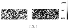
- FIG. 1 illustrates Raman spectral images of micro-region of positive electrode plates prepared in an example and a comparative example provided in the present disclosure.
- An example of the present disclosure provides a positive electrode plate.
- the positive electrode plate includes a current collector and a positive electrode active layer arranged on the current collector.
- the positive electrode active layer includes m positive electrode active sub-layers.
- a positive electrode active material in each of the positive electrode active sub-layers includes a main positive electrode material and an auxiliary positive electrode material.
- the D 50 particle size of the main positive electrode material in the positive electrode active layer satisfies: 1 / 2 ⁇ 1 n ⁇ 1 D 501 ⁇ D 50 n ⁇ 2 2 + 1 n ⁇ 1 D 501
- the n is any integer ranging from 2 to m
- the D 501 represents the D 50 particle size of the main positive electrode material in a first positive electrode active sub-layer
- the D 50 n represents the D 50 particle size of the main positive electrode material in an nth positive electrode active sub-layer
- the distance between the nth positive electrode active sub-layer and the current collector is greater than the distance between a (n-1)th positive electrode active sub-layer and the current collector.
- the D 90 particle size of the auxiliary positive electrode material is less than the D 10 particle size of the main positive electrode material in the first positive electrode active sub-layer. That is, the particle size of the auxiliary positive electrode material and the particle size of the main positive electrode material in the first positive electrode active sub-layer satisfy D 90 auxiliary ⁇ D 101 , where the D 90 auxiliary represents the D 90 particle size of the auxiliary positive electrode material, and the D 101 represents the D 10 particle size of the main positive electrode material in the first positive electrode active sub-layer.
- the m positive electrode active sub-layers are arranged on the same side of the current collector. In the direction far away from the current collector, the m positive electrode active sub-layers successively include a first positive electrode active sub-layer, a second positive electrode active sub-layer ... a (m-1)th positive electrode active sub-layer and an mth positive electrode active sub-layer.
- the first positive electrode active sub-layer is in direct contact with the current collector.
- the m is an integer ranging from 3 to 6. In another example, the m is equal to 4.
- the D 50 particle size of the main positive electrode material in the positive electrode active layer satisfies: 1 / 2 ⁇ 1 n-1 D 501 ⁇ D 50 n ⁇ 2 2 + 1 n ⁇ 1 D 501 . That is to say, the D 50 particle size of any positive electrode active sub-layer of the m positive electrode active sub-layers and the D 50 particle size of the first positive electrode active sub-layer satisfy the relational expression I.
- the D 50 particle size from the first positive electrode active sub-layer to the mth positive electrode active sub-layer increases gradually, the D 50 particle size of the first positive electrode active sub-layer near the current collector is the smallest, and the D 50 particle size of the mth positive electrode active sub-layer farthest from the current collector is the largest.
- the middle layer shows a gradient distribution from small particle size to large particle size.
- the particle size of the main positive electrode material of the positive electrode active layer increases gradually from the current collector to the side far from the current collector, so that the lithium ion deintercalation/intercalation speed in the entire positive electrode active layer is uniform, thus making the charge distribution between adjacent particles in the thickness direction of the positive electrode plate uniform, reducing the polarization caused by different state of charge in the thickness direction of the positive electrode plate and different state of charge between the large and small particles, improving the electric conductivity of the prepared battery, and improving the rate performance, the safety performance and the like of the prepared battery.
- the transmission of lithium ions in the battery is mainly affected by two aspects, one is solid phase diffusion, that is, the particle size of the active material in the electrode, the other is liquid phase diffusion, that is, the diffusion distance of lithium ions in the liquid phase environment.
- solid phase diffusion that is, the particle size of the active material in the electrode
- liquid phase diffusion that is, the diffusion distance of lithium ions in the liquid phase environment.
- the lithium ion deintercalation/intercalation speed of the active material in the surface layer (near the separator) of the electrode plate is caused to be fast, while the lithium ion deintercalation/intercalation speed of the active material in the inner layer (near the current collector) of the electrode plate is caused to be slow, leading to uneven distribution of the state of charge between the active material particles, resulting in large battery impedance, poor rate and fast cycle attenuation.
- the deintercalation/intercalation speed of the lithium ions of large positive electrode material particles is slower than that of small main positive electrode material particles, leading to uneven distribution of the state of charge among the positive electrode material particles, resulting in large battery impedance, poor rate and fast cycle attenuation.
- the lithium ion deintercalation/intercalation speed of the large positive electrode material particles is slower, while the lithium ion deintercalation/intercalation speed of the small positive electrode material particles is faster.
- the particle size of the main positive electrode material particles in the positive electrode active sub-layer adjacent to the electrolyte is set to be larger, and the particle size of the main positive electrode material particles in the positive electrode active sub-layer far from the electrolyte (near the side of the current collector) is set to be smaller.
- the lithium ion deintercalation/intercalation speed of the large main positive electrode material particles adjacent to the electrolyte is equivalent to the lithium ion deintercalation/intercalation speed of the small main positive electrode material particles far from the electrolyte, so that the lithium ion deintercalation/intercalation speed of the positive electrode active material in each of the positive electrode active sub-layers is the same, thus improving the consistency of the lithium ion deintercalation/intercalation speed of the overall positive electrode active layer.
- the particle size of the main positive electrode material particles in the first positive electrode active sub-layer is the smallest, and the time for lithium ions to release from the main positive electrode material particles is short, but the first positive electrode active sub-layer is the farthest from the electrolyte, and the released lithium ions take longer time to enter the electrolyte.
- the particle size of the main positive electrode material particles in the mth positive electrode active sub-layer is the largest, and the lithium ions take longer time to release from the main positive electrode material particles, but the mth positive electrode active sub-layer is the closest to the electrolyte, and the lithium ions only take shorter time to enter the electrolyte.
- the total time for the lithium ions to release from the main positive electrode material particles of the first positive electrode active sub-layer and arrive at the electrolyte tends to be the same as the total time for the lithium ions to release from the main positive electrode material particles of the mth positive electrode active sub-layer and arrive at the electrolyte, that is, the deintercalation/intercalation speed of the lithium ions in the first positive electrode active sub-layer is equivalent to the deintercalation/intercalation speed of the lithium ions in the mth positive electrode active sub-layer.
- the deintercalation/intercalation speed of the lithium ions in the second positive electrode active sub-layer is equivalent to that in the (m-1)th positive electrode active sub-layer, and the deintercalation/intercalation speed of the lithium ions in adjacent nth and (n-1)th positive electrode active sub-layers is also equivalent, or the deintercalation/intercalation speed of the lithium ions in any two positive electrode active sub-layers of the positive electrode active layer is equivalent.
- the D 50 particle size of the main positive electrode material in each of the positive electrode active sub-layer of the positive electrode active layers is distributed according to the above relational expression, so that the deintercalation/intercalation speed of the lithium ions in the entire positive electrode active layer is uniform, thus making the charge distribution between adjacent particles in the thickness direction of the positive electrode plate uniform, and reducing the polarization caused by different state of charge in the thickness direction of the positive electrode plate and different state of charge between the large and small particles.
- the positive electrode active material in the present disclosure is also provided with an auxiliary positive electrode material layer.
- the particle size of the auxiliary positive electrode material and the particle size of the main positive electrode material in the first positive electrode active sub-layer satisfy: D 90 auxiliary ⁇ D 101 , that is, the particle size of 90% of the auxiliary positive electrode material is less than the particle size of 10% of the main positive electrode material in the positive electrode active sub-layer, and the small auxiliary positive electrode material particles are distributed in the gaps between the large main positive electrode material particles in each of the positive electrode active sub-layers, thus effectively increasing the compacted density of the positive electrode plate.
- the main positive electrode material is preferably a layered positive electrode material
- the auxiliary positive electrode material is preferably a polyanion positive electrode material.
- the polyanion positive electrode material has excellent structural stability.
- the polyanion positive electrode is not easy to react with the electrolyte, or has little impact on the structure of the positive electrode active layer when reacting with the electrolyte, and will not damage the structural stability of the positive electrode active layer.
- the cycle and safety performance of the positive electrode plate can be improved by the joint use of the polyanion positive electrode material and the layered positive electrode material.
- the layered positive electrode material may be a layered positive electrode material formed by coating and compacting the main positive electrode material.
- the positive electrode plate provided by the present disclosure, under the situation that the particle size of the main positive electrode material in each of the positive electrode active sub-layers of the positive electrode active layer is set to satisfy the above relational expression I, and the small auxiliary positive electrode material particles are also filled in the gap among the large main positive electrode material particles, the uniformity of the charge distribution between adjacent particles in the thickness direction of the positive electrode plate is improved, and the polarization caused by different state of charge in the thickness direction of the positive electrode plate and different state of charge between the large and small particles, thus further effectively increasing the compacted density of the positive electrode plate.
- the D 50 particle size of the auxiliary positive electrode material is less than or equal to 200 nm. That is, the particle size of the auxiliary positive electrode material satisfies D 50 auxiliary ⁇ 200 nm, and the D 50 auxiliary represents the D 50 particle size of the auxiliary positive electrode material.
- the auxiliary positive electrode material can be better distributed among the main positive electrode material particles, thus further improving the compacted density of the positive electrode plate.
- the D 90 particle size of the main positive electrode material in the (n-1)th positive electrode active sub-layer is less than or equal to the D 10 particle size of the main positive electrode material in the nth positive electrode active sub-layer. That is, the particle size of the main positive electrode material in the (n-1)th positive electrode active sub-layer and the particle size of the main positive electrode material in the nth positive electrode active sub-layer satisfy D 90 n-1 ⁇ D 10 n , where D 90 n-1 represents the D 90 particle size of the main positive electrode material in the (n-1)th positive electrode active sub-layer, and D 10 n represents the D 10 particle size of the main positive electrode material in the nth positive electrode active sub-layer.
- the particle size of 90% of the main positive electrode material in the (n-1)th positive electrode active sub-layer is smaller than the particle size of 10% of the main positive electrode material in the nth positive electrode active sub-layer. In this way, it is ensured that the particle size of the main positive electrode material particles in the adjacent two layers gradually transitions from small particle size to large particle size. For the entire positive electrode active layer, it can further improve the gradient regularity of the particle size distribution of the main positive electrode material particles in each of the positive electrode active sub-layers.
- the particle size of the main positive electrode material in the positive electrode active layer further satisfies 4.0 ⁇ m ⁇ D 50 [m/2]+1 ⁇ 8.0 ⁇ m
- the [m/2] represents rounding down
- the D 50 [m/2]+1 represents the D 50 particle size of the main positive electrode material in a ([m/2]+1)th positive electrode active sub-layer.
- the particle size of the main positive electrode material in the positive electrode active layer satisfies 4.0 ⁇ m ⁇ D 503 ⁇ 8.0 ⁇ m. That is to say, the D 50 particle size of the third positive electrode active sub-layer is between 4.0 ⁇ m and 8.0 ⁇ m.
- the particle size of the main positive electrode material in the positive electrode active layer satisfies 4.0 ⁇ m ⁇ D 503 ⁇ 8.0 ⁇ m. That is to say, the D 50 particle size of the third positive electrode active sub-layer is between 4.0 ⁇ m and 8.0 ⁇ m.
- the above setting defines the particle size of the main positive electrode material close to the middle layer or in the middle layer.
- the particle size distribution of the main positive electrode material in the first positive electrode active sub-layer to the last positive electrode active sub-layer can be known through the relational expression I of particle size distribution of the sub-layers.
- the percentage of the surface density of the main positive electrode material in each of the first positive electrode active sub-layer to an mth positive electrode active sub-layer to the surface density of the main positive electrode material in the positive electrode active layer shows a normal distribution.
- the surface density of the main positive electrode material in the positive electrode active layer refers to the mass of the main positive electrode material in the positive electrode active layer on a unit area under a specified thickness
- the surface density of the main positive electrode material in the positive electrode active sub-layer refers to the mass of the main positive electrode material in the positive electrode active sub-layer on a unit area under a specified thickness.
- the surface densities of the main positive electrode material in the positive electrode active sub-layer at both ends of the positive electrode active layer are small, and the surface density of the main positive electrode material in the positive electrode active sub-layer of the middle layer is large. This distribution can improve the uniformity of the charge distribution between adjacent particles in the thickness direction of the positive electrode plate.
- the surface density of the main positive electrode material in the positive electrode active sub-layers at both ends is set to be smaller, thus reducing the amount of the main positive electrode material particles with large lithium ion deintercalation/intercalation speed difference at both ends, improving the consistency of lithium ion deintercalation/intercalation speed in the entire positive electrode active layer, and improving the charge distribution uniformity between adjacent particles in the thickness direction of the positive electrode plate.
- the percentage of the surface density of the main positive electrode material in each of the positive electrode active sub-layers to the surface density of the main positive electrode material in the positive electrode active layer satisfies: ⁇ 1 ⁇ 10.0 % , ⁇ m ⁇ 10.0 % ; ⁇ 2 ⁇ 10.0 % , ⁇ m-1 ⁇ 10.0 % ; 40.0 % ⁇ ⁇ m/2 ⁇ 60.0 % , where the m is an integer equal to or greater than 3, the ⁇ 1 represents the percentage of the surface density of the main positive electrode material in the first positive electrode active sub-layer to the surface density of the main positive electrode material in the positive electrode active layer, the ⁇ 2 represents the percentage of the surface density of the main positive electrode material in the second positive electrode active sub-layer to the surface density of the main positive electrode material in the positive electrode active layer, the ⁇ m represents the percentage of the surface density of the main positive electrode material in the mth positive electrode active sub-layer to the surface density of
- the ⁇ m/2 represents the percentage of the surface density of the main positive electrode material in the ([m/2]+1)th positive electrode active sub-layer to the surface density of the main positive electrode material in the positive electrode active layer, and the [m/2] represents rounding down; and when the m is an even number, the ⁇ m/2 represents the percentage of the surface density of the main positive electrode material in at least one of the ([m/2])th positive electrode active sub-layer and the ([m/2]+1)th positive electrode active sub-layer to the surface density of the main positive electrode material in the positive electrode active layer.
- each of the positive electrode active sub-layers further includes a conductive agent and a binder.
- the surface density of the positive electrode active layer satisfies 300 g/m 2 ⁇ 500 g/m 2 , where the ⁇ represents the surface density of the positive electrode active layer.
- the positive electrode active layer includes a main positive electrode material, an auxiliary positive electrode material, a conductive agent and a binder.
- the surface density of the positive electrode active layer refers to the mass of all of the main positive electrode material, the auxiliary positive electrode material, the conductive agent and the binder in the positive electrode active layer on a unit area under a specified thickness.
- the surface density of the positive electrode active layer is large and between 300 g/m 2 and 500 g/m 2 , so that the positive electrode active layer has a high electric capacity.
- the positive electrode active layer with higher surface density has a greater thickness on the positive electrode plate with the same area.
- the larger the thickness of the positive electrode active layer the more obvious the improvement of the distribution of the state of charge among the positive electrode material particles of the positive electrode plate is obtained by adopting the relational expression I of particle size distribution of each of the positive electrode active sub-layers.
- the thicker the positive electrode plate is the more obvious the effect of improving the electric performance of the positive electrode plate is when the setting of the relational expression I is adopted.
- the impedance of the positive electrode plate can be reduced, the charge uniformity of the positive electrode plate can be improved, and the rate performance of the prepared battery can be improved.
- the conductive agent is at least one of conductive carbon black, acetylene black, carbon nanotubes and graphene.
- the binder is polyvinylidene fluoride or a copolymer containing vinylidene fluoride.
- the surface density of the positive electrode active layer satisfies 350 g/m 2 ⁇ 450 g/m 2 . In another example, the surface density of the positive electrode active layer satisfies 400 g/m 2 ⁇ 450 g/m 2 .
- the mass of the auxiliary positive electrode material accounts for 0.5%-20.0% of the mass of the positive electrode active material in the positive electrode active layer.
- the mass of the auxiliary positive electrode material accounts for 4.0%-12.0% of the mass of the positive electrode active material in the positive electrode active layer.
- the layered positive electrode material is at least one of lithium cobaltate, lithium nickelate, lithium manganate, lithium nickel cobalt manganate and lithium nickel cobalt aluminate; and the polyanion positive electrode material is at least one of lithium iron phosphate, lithium manganese iron phosphate, lithium manganese phosphate, lithium vanadium phosphate, lithium vanadium fluorophosphate, lithium manganese silicate, lithium iron silicate and lithium cobalt silicate.
- the present disclosure further provides a battery, including the positive electrode plate as described in the above examples.
- Arranging the electrode plate in the battery can reduce the polarization caused by different charge in the thickness direction of the positive electrode plate and different charge between the large and small particles, eliminate the polarization caused by the uneven lithium ion deintercalation/intercalation, reduce the impedance of the battery, and improve the electrochemical performance and cycle performance of the battery at different rates.
- Second positive electrode slurry was prepared according to the above steps.
- Third positive electrode slurry was prepared according to the above steps.
- the fourth positive electrode slurry was prepared according to the above steps.
- a positive electrode plate was prepared by adopting the same method in example 1, the difference was that the number of the D 50 particle sizes of the layered positive electrode material selected for preparing the positive electrode active sub-layers was 3, the D 50 particle sizes of the layered positive electrode material in the first positive electrode active sub-layer, the second positive electrode active sub-layer and the third positive electrode active sub-layer were 2.0 ⁇ m, 6.5 ⁇ m and 15.0 ⁇ m respectively, and the D 50 particle sizes in the 3 layers satisfied relational expression I. Other conditions were the same as those in example 1. The positive electrode plate was obtained.
- a positive electrode plate was prepared by adopting the same method in example 1, the difference was that the number of the D 50 particle sizes of the layered positive electrode material selected for preparing the positive electrode active sub-layers was 5, the D 50 particle sizes of the layered positive electrode material in the first positive electrode active sub-layer, the second positive electrode active sub-layer, the third positive electrode active sub-layer, the fourth positive electrode active sub-layer and the fifth positive electrode active sub-layer were 0.5 ⁇ m, 1.5 ⁇ m, 4.5 ⁇ m, 8.0 ⁇ m and 18.0 ⁇ m respectively, and the D 50 particle sizes in the 5 layers satisfied relational expression I. Other conditions were the same as those in example 1. The positive electrode plate was obtained.
- a positive electrode plate was prepared by adopting the same method in example 1, the difference was that the D 50 particle size of lithium iron phosphate was 125 nm. The positive electrode plate was obtained.
- a positive electrode plate was prepared by adopting the same method in example 1, the difference was that the D 50 particle size of lithium iron phosphate was 300 nm. The positive electrode plate was obtained.
- a positive electrode plate was prepared by adopting the same method in example 1, the difference was that the layered positive electrode material selected was a mixture of lithium cobaltate and lithium nickel cobalt aluminate with a molar ratio of 1:1. The positive electrode plate was obtained.
- a positive electrode plate was prepared by adopting the same method in example 1,. the difference was that the content of lithium iron phosphate in the positive electrode active material was 15.0%. The positive electrode plate was obtained.
- a positive electrode plate was prepared by adopting the same method in example 1, the difference was that the content of lithium iron phosphate in the positive electrode active material was 2.0%. The positive electrode plate was obtained.
- a positive electrode plate was prepared by adopting the same method in example 1, the difference was that the polyanion in the positive electrode active material was lithium manganese iron phosphate. The positive electrode plate was obtained.
- a positive electrode plate was prepared by adopting the same method in example 1, the difference was that the positive electrode active material did not contain the polyanion positive electrode. The positive electrode plate was obtained.
- the positive electrode plate was obtained.
- a positive electrode plate was prepared by adopting the same method in example 1, the difference was that the number of the D 50 particle sizes of the layered positive electrode material selected for preparing the positive electrode active sub-layers was 4, and the D 50 particle sizes of LiNi 0.83 Co 0.13 Mn 0.04O2 in the first positive electrode active sub-layer, the second positive electrode active sub-layer, the third positive electrode active sub-layer and the fourth positive electrode active sub-layer were 0.6 ⁇ m, 3.0 ⁇ m, 7.0 ⁇ m and 20.0 ⁇ m respectively.
- the positive electrode plate was obtained.
- the positive electrode plates in examples 1 to 9 and in comparative examples 1 to 4 above were used to prepare batteries to obtain the corresponding batteries according to the following method: the positive electrode plate, the separator and the negative electrode plate were stacked sequentially to obtain a bare battery core, then the battery core was put into a housing, baking and drying were performed, electrolyte was injected, welding and sealing were performed, and high-temperature aging, formation and aging processes were performed to obtain a battery.
- Performance tests including impedance performance test, rate performance test, cycle performance test, safety performance test and state of charge performance test, were performed on the batteries prepared by adopting the corresponding positive electrode plates in examples 1 to 9 and comparative examples 1 to 4 above. See FIG. 1 and Table 1 for specific data.
- Impedance performance test method at 25°C, the battery was fully charged with 0.2C constant current and constant voltage, and then discharged to 2.5 V with 0.2C constant current after shelving, the operation was repeated for 3 times, the discharge capacity at the 3 rd time was recorded as C0, the battery was adjusted to 50% SOC with 0.2C0 current, and then 1.5C constant current discharge for 30s was tested to calculate the impedance value.
- Rate performance test method at 25°C, the battery was fully charged with 0.2C constant current and constant voltage, and then discharged to 2.5 V with 0.2C constant current after shelving, the operation was repeated for 3 times, the discharge capacity at the 3 rd time was recorded as C0, the battery was fully charged with 0.2C0 and 5.0C0 constant current and constant voltage respectively, and then was fully discharged with the same current, the 0.2C0 discharge capacity was used as the benchmark, and the ratio of the 5.0C0 discharge capacity to the 0.2C0 discharge capacity was used as the indicator to evaluate the rate performance.
- Cycle performance test method at 25°C, the battery was fully charged with 0.2C constant current and constant voltage, and then discharged to 2.5 V with 0.2C constant current after shelving, the operation was repeated for 3 times, the discharge capacity at the 3 rd time was recorded as C0, the battery was fully charged with 1.0C0 constant current and constant voltage in a 45°C environment, and then was discharged with 1.0C0 constant current, 500 cycles were performed, and the capacity retention rate was recorded.
- Safety performance test method the electrode stability was tested by DSC as the indicator to evaluate the safety performance, the battery was fully charged, the positive electrode plate was taken out in a glove box, an appropriate amount of the positive electrode material was scraped and put into a crucible, a certain amount of electrolyte was added, the crucible was transferred to a device, the test atmosphere was pure argon, the heating rate was 2°C/min, and the initial temperature of thermal runaway, the peak temperature of thermal runaway, and the exothermic power were recorded respectively.
- SOC State of charge performance test method: the battery was fully charged rapidly with 2.0C current, the positive electrode plate was taken out in a glove box and cut with an Ar ion beam to obtain an electrode plate section, and then the electrode plate section was placed on the Raman spectrum for cross-section scanning.
- the vibration energy levels of different metals and oxygen/different-valence metals and oxygen are different, and the peak position, peak type and peak intensity in the Raman spectrum are different.
- the area ratio of 550 cm -1 peak to 470 cm -1 peak was used as the indicator to evaluate the SOC. The ratio of each point in the scanning area could be obtained, so that the distribution of the SOC in the area could be obtained, and then the average value of the SOC in the area could be calculated to characterize the actual SOC of the electrode plate.
- FIG. 1 Please refer to FIG. 1 .
- the left side is the SOC distribution of the battery prepared corresponding to example 1
- the right side is the SOC distribution of the battery prepared corresponding to comparative example 3. It can be seen that the SOC distribution in the positive electrode plate prepared according to example 1 is obviously more uniform, indicating that the positive electrode plate has less polarization, and is more conducive to the intercalation/deintercalation of lithium ions.
- Example 1 S/N Impedance (m ⁇ ) Rate (%) Capacity retention rate (%) DSC SOC (%) Initial temperature of thermal runaway (°C) Peak temperature of thermal runaway (°C) Exothermic power (J/g)
- Example 1 154 98.5 92.1 201.5 207.5 1027.5 97.5
- Example 2 175 93.0 84.3 199.1 205.4 1026.5 89.2
- Example 3 177 92.5 83.5 199.8 206.2 1028.3 88.4
- Example 4 151 99.3 93.2 202.9 209.2 1027.5 98.7
- Example 5 181 91.4 82.0 198.7 204.9 1022.3 86.8
- Example 6 158 97.5 90.6 199.6 205.7 1030.4 95.9
- Example 7 201 86.2 87.1 204.2 210.2 948.4 92.2
- examples 1 to 9 are better than that of comparative examples 1-4.
- the lowest battery impedance value in examples 1 to 9 can reach 151 m• ⁇ , and the lower the battery impedance value is, the better the conductivity of the battery is; and in terms of rate performance, the highest rate ratio is 99.3%, and the lowest rate ratio is 86.2%.
- the prepared battery is worse than that prepared in example 1 in terms of the impedance, rate, cycle capacity retention rate, safety performance and SOC.
- the battery impedance in comparative example 1 is 195 m• ⁇ , and is larger than that in example 1, indicating that the conductivity of the battery is reduced; and the rate is only 87.8%, the capacity retention rate is only 76.8%, the initial temperature and peak temperature of thermal runaway are lower than those in example 1, the exothermic power is greater than that in example 1, and the SOC ratio is lower than that in example 1.
- the polyanion positive electrode material is not added in comparative example 2, the compacted density of the positive electrode plate is affected, and then the conductivity of the positive electrode plate is affected. From the data of comparative example 2, it can be seen that the battery prepared in comparative example 2 is worse than that prepared in example 1 in terms of impedance, rate, cycle capacity retention rate, safety performance and SOC.
- comparative example 3 there is only one particle size added in comparative example 3 and the polyanion positive electrode material is not added. From the data of comparative example 3, it can be seen that the battery prepared in comparative example 3 is worse than that prepared in example 1 in terms of impedance, rate, cycle capacity retention rate, safety performance and SOC.
- the D 50 particle size of LiNi 0.83 Co 0.13 Mn 0.04O2 in the four positive electrode active sub-layers in comparative example 4 does not satisfy the relational expression I in the present disclosure, that is, the particle size of the particles between the sub-layers does not show the regular distribution in the relational expression I.
- the battery prepared in comparative example 4 is worse than that prepared in example 1 in terms of impedance, rate, cycle capacity retention rate, safety performance and SOC, indicating that setting the D 50 particle size of LiNi 0.83 Co 0.13 Mn 0.04O2 in each of the positive electrode active sub-layers according to the relational expression I in the present disclosure can improve the electric performance of the battery.
- example 7 and example 8 By comparing example 7 and example 8 with example 1, it can be seen that the performance of the positive electrode plate prepared by adopting the lithium iron phosphate positive electrode material with the mass accounting for 6.5% of the mass of the positive electrode material is better.
- the performance of the positive electrode plate prepared when adopting the auxiliary positive electrode material with the mass accounting for 4.0%-12.0% of the mass of the positive electrode active material in the positive electrode active layer is better.
- the positive electrode plate with the particle size distribution satisfying the relational expression I in the present disclosure can reduce the polarization caused by different SOC in the thickness direction of the positive electrode plate and different SOC between the large and small particles, eliminate the polarization caused by uneven lithium ion intercalation, reduce the battery impedance, and improve the rate and cycle performance.
- the polyanion positive electrode material has excellent structural stability. Through joint use, not only the cycle performance is improved, but also the safety performance (thermal stability) is improved.
Landscapes
- Chemical & Material Sciences (AREA)
- Chemical Kinetics & Catalysis (AREA)
- Electrochemistry (AREA)
- General Chemical & Material Sciences (AREA)
- Inorganic Chemistry (AREA)
- Engineering & Computer Science (AREA)
- Materials Engineering (AREA)
- Manufacturing & Machinery (AREA)
- Composite Materials (AREA)
- Crystallography & Structural Chemistry (AREA)
- Battery Electrode And Active Subsutance (AREA)
- Secondary Cells (AREA)
Applications Claiming Priority (2)
| Application Number | Priority Date | Filing Date | Title |
|---|---|---|---|
| CN202010585072.2A CN113839028B (zh) | 2020-06-24 | 2020-06-24 | 正极片及电池 |
| PCT/CN2021/093563 WO2021258900A1 (fr) | 2020-06-24 | 2021-05-13 | Feuille d'électrode positive et batterie |
Publications (2)
| Publication Number | Publication Date |
|---|---|
| EP4174980A1 true EP4174980A1 (fr) | 2023-05-03 |
| EP4174980A4 EP4174980A4 (fr) | 2024-10-02 |
Family
ID=78964369
Family Applications (1)
| Application Number | Title | Priority Date | Filing Date |
|---|---|---|---|
| EP21830200.8A Pending EP4174980A4 (fr) | 2020-06-24 | 2021-05-13 | Feuille d'électrode positive et batterie |
Country Status (6)
| Country | Link |
|---|---|
| US (1) | US20230253549A1 (fr) |
| EP (1) | EP4174980A4 (fr) |
| JP (1) | JP7596410B2 (fr) |
| KR (1) | KR102891402B1 (fr) |
| CN (1) | CN113839028B (fr) |
| WO (1) | WO2021258900A1 (fr) |
Families Citing this family (5)
| Publication number | Priority date | Publication date | Assignee | Title |
|---|---|---|---|---|
| CN116646516A (zh) * | 2022-02-15 | 2023-08-25 | 比亚迪股份有限公司 | 一种磷酸铁锂正极活性材料、正极极片及锂离子电池 |
| CN114400322B (zh) * | 2022-02-21 | 2024-05-14 | 远景动力技术(江苏)有限公司 | 正极活性材料、电化学装置和电子设备 |
| CN114636887B (zh) * | 2022-05-20 | 2022-07-22 | 石家庄嘉硕电子技术有限公司 | 脱嵌电极板对的状态检测方法、一致性检测方法及装置 |
| CN119230745B (zh) * | 2023-06-28 | 2026-03-17 | 宁德时代新能源科技股份有限公司 | 正极片及其制备方法、锂离子电池以及用电装置 |
| CN117410494B (zh) * | 2023-12-15 | 2024-03-15 | 溧阳中科海钠科技有限责任公司 | 一种正极极片及其制备方法、钠离子电池和用电设备 |
Family Cites Families (22)
| Publication number | Priority date | Publication date | Assignee | Title |
|---|---|---|---|---|
| JP2006210003A (ja) * | 2005-01-25 | 2006-08-10 | Nissan Motor Co Ltd | 電池用電極 |
| JP4513822B2 (ja) | 2007-03-30 | 2010-07-28 | Tdk株式会社 | 電極及び電気化学デバイス |
| CN101483235B (zh) * | 2009-02-11 | 2011-02-16 | 深圳新宙邦科技股份有限公司 | 电池电极片及其制备方法以及由该电极片制备的电池 |
| KR101407085B1 (ko) * | 2011-05-02 | 2014-06-19 | 주식회사 엘지화학 | 다층의 전극 활물질층을 포함하는 전극 및 이를 포함하는 이차 전지 |
| JP5929183B2 (ja) | 2011-12-28 | 2016-06-01 | 株式会社豊田中央研究所 | 電極、リチウム二次電池及び電極の製造方法 |
| CN103746089B (zh) * | 2013-12-11 | 2016-05-11 | 中南大学 | 一种具有梯度结构的全固态锂电池及其制备方法 |
| TWI570752B (zh) * | 2013-12-11 | 2017-02-11 | 財團法人工業技術研究院 | 儲能元件與超級電容器元件 |
| KR102305509B1 (ko) * | 2014-07-22 | 2021-09-28 | 씨-나노 테크놀로지 리미티드 | 배터리용 전극 조성물 |
| JP6287707B2 (ja) * | 2014-09-08 | 2018-03-07 | トヨタ自動車株式会社 | 非水電解質二次電池 |
| CN105958051A (zh) * | 2016-06-06 | 2016-09-21 | 中国工程物理研究院电子工程研究所 | 一种异质结锂离子薄膜电池电极材料及其制备方法 |
| KR102135284B1 (ko) | 2016-06-14 | 2020-07-17 | 주식회사 엘지화학 | 이차전지용 전극 및 이를 포함하는 리튬 이차 전지 |
| CN106252586B (zh) * | 2016-08-30 | 2018-12-11 | 深圳博磊达新能源科技有限公司 | 一种复合正极片及其制备方法、锂离子电池 |
| JP6617312B2 (ja) * | 2017-02-27 | 2019-12-11 | 住友大阪セメント株式会社 | リチウムイオン二次電池用電極、リチウムイオン二次電池 |
| JP7069668B2 (ja) * | 2017-12-01 | 2022-05-18 | トヨタ自動車株式会社 | リチウムイオン二次電池 |
| KR102410662B1 (ko) * | 2018-02-01 | 2022-06-17 | 주식회사 엘지에너지솔루션 | 이차전지용 양극 활물질, 그 제조방법 및 이를 포함하는 리튬 이차전지 |
| CN110556538B (zh) * | 2018-06-01 | 2021-05-04 | 宁德时代新能源科技股份有限公司 | 正极片及锂离子电池 |
| KR102553570B1 (ko) * | 2018-06-27 | 2023-07-10 | 삼성전자 주식회사 | 리튬 이온 전지용 양극 활물질 및 이를 포함하는 리튬 이온 전지 |
| WO2020017580A1 (fr) | 2018-07-19 | 2020-01-23 | 株式会社Gsユアサ | Élément de stockage d'énergie |
| JP6627932B1 (ja) * | 2018-08-21 | 2020-01-08 | 住友大阪セメント株式会社 | リチウムイオン二次電池用正極材料、リチウムイオン二次電池用電極、及びリチウムイオン二次電池 |
| KR102657451B1 (ko) * | 2018-10-19 | 2024-04-16 | 주식회사 엘지에너지솔루션 | 이차전지용 양극재 및 이를 포함하는 리튬 이차전지 |
| CN111261834A (zh) | 2020-03-25 | 2020-06-09 | 宁德新能源科技有限公司 | 负极极片、电化学装置和电子装置 |
| DE112022002815T5 (de) * | 2021-05-28 | 2024-03-07 | Semiconductor Energy Laboratory Co., Ltd. | Batterie, elektronisches Gerät, Energiespeichersystem und beweglicher Gegenstand |
-
2020
- 2020-06-24 CN CN202010585072.2A patent/CN113839028B/zh active Active
-
2021
- 2021-05-13 KR KR1020237001997A patent/KR102891402B1/ko active Active
- 2021-05-13 US US18/012,599 patent/US20230253549A1/en active Pending
- 2021-05-13 JP JP2022580298A patent/JP7596410B2/ja active Active
- 2021-05-13 EP EP21830200.8A patent/EP4174980A4/fr active Pending
- 2021-05-13 WO PCT/CN2021/093563 patent/WO2021258900A1/fr not_active Ceased
Also Published As
| Publication number | Publication date |
|---|---|
| KR20230027203A (ko) | 2023-02-27 |
| WO2021258900A1 (fr) | 2021-12-30 |
| KR102891402B1 (ko) | 2025-11-27 |
| EP4174980A4 (fr) | 2024-10-02 |
| CN113839028A (zh) | 2021-12-24 |
| CN113839028B (zh) | 2023-02-10 |
| US20230253549A1 (en) | 2023-08-10 |
| JP2023531266A (ja) | 2023-07-21 |
| JP7596410B2 (ja) | 2024-12-09 |
Similar Documents
| Publication | Publication Date | Title |
|---|---|---|
| US20230108289A1 (en) | Positive-electrode material, positive electrode plate, lithium secondary battery, battery module, battery pack, and apparatus | |
| EP4174980A1 (fr) | Feuille d'électrode positive et batterie | |
| EP4243116A1 (fr) | Batterie au lithium-ion | |
| JP7337049B2 (ja) | リチウムイオン二次電池用正極組成物、リチウムイオン二次電池用正極、及びリチウムイオン二次電池 | |
| US20230343933A1 (en) | Negative electrode active material, electrochemical apparatus, and electronic apparatus | |
| US20130122366A1 (en) | Cathode plate for secondary battery, manufacturing method thereof and secondary battery provided with the cathode plate | |
| EP4024511A1 (fr) | Matériau actif d'anode à base de carbone globulaire, procédé pour sa préparation, et anode et batterie secondaire au lithium le comprenant | |
| EP3951977A1 (fr) | Batterie secondaire et module de batterie, bloc-batterie et dispositif le contenant | |
| EP4152462A1 (fr) | Batterie au métal-sodium à plaque plate et appareil électrochimique | |
| CN116169249A (zh) | 一种负极片、二次电池以及用电设备 | |
| WO2016201941A1 (fr) | Batterie au lithium-ion à performance de cycle longue | |
| EP4542685A2 (fr) | Matériau d'électrode positive, feuille d'électrode positive et batterie | |
| KR20140108380A (ko) | 실리콘-금속 합금계 음극 활물질을 포함하는 이차전지 | |
| WO2012124525A1 (fr) | Batterie secondaire à électrolyte non aqueux et son procédé de fabrication | |
| EP4283706A1 (fr) | Plaque d'électrode négative et son application | |
| EP4718617A1 (fr) | Séparateur, appareil électrochimique et dispositif électronique | |
| EP4685861A1 (fr) | Batterie secondaire et dispositif électrique | |
| CN106374091A (zh) | 一种锂离子动力电池及其制备方法 | |
| CN116759540A (zh) | 一种磷酸锰铁锂复合电极极片及其制备方法与应用 | |
| EP4579788A1 (fr) | Ensemble de réapprovisionnement en lithium, électrode positive, batterie secondaire et dispositif électronique | |
| CN118248832B (zh) | 一种负极片、电池及用电设备 | |
| CN115472777A (zh) | 负极极片、二次电池及用电设备 | |
| CN115440933A (zh) | 负极极片、电池、电池包及用电设备 | |
| EP4579786A1 (fr) | Électrode, batterie secondaire et dispositif électrique | |
| EP4376116A1 (fr) | Pièce polaire d'électrode négative, batterie, bloc-batterie et dispositif électrique |
Legal Events
| Date | Code | Title | Description |
|---|---|---|---|
| STAA | Information on the status of an ep patent application or granted ep patent |
Free format text: STATUS: THE INTERNATIONAL PUBLICATION HAS BEEN MADE |
|
| PUAI | Public reference made under article 153(3) epc to a published international application that has entered the european phase |
Free format text: ORIGINAL CODE: 0009012 |
|
| STAA | Information on the status of an ep patent application or granted ep patent |
Free format text: STATUS: REQUEST FOR EXAMINATION WAS MADE |
|
| 17P | Request for examination filed |
Effective date: 20230111 |
|
| AK | Designated contracting states |
Kind code of ref document: A1 Designated state(s): AL AT BE BG CH CY CZ DE DK EE ES FI FR GB GR HR HU IE IS IT LI LT LU LV MC MK MT NL NO PL PT RO RS SE SI SK SM TR |
|
| DAV | Request for validation of the european patent (deleted) | ||
| DAX | Request for extension of the european patent (deleted) | ||
| A4 | Supplementary search report drawn up and despatched |
Effective date: 20240829 |
|
| RIC1 | Information provided on ipc code assigned before grant |
Ipc: H01M 4/505 20100101ALI20240823BHEP Ipc: H01M 4/485 20100101ALI20240823BHEP Ipc: H01M 4/139 20100101ALI20240823BHEP Ipc: H01M 4/02 20060101ALI20240823BHEP Ipc: H01M 10/0525 20100101ALI20240823BHEP Ipc: H01M 10/052 20100101ALI20240823BHEP Ipc: H01M 4/58 20100101ALI20240823BHEP Ipc: H01M 4/525 20100101ALI20240823BHEP Ipc: H01M 4/36 20060101ALI20240823BHEP Ipc: H01M 4/136 20100101ALI20240823BHEP Ipc: H01M 4/131 20100101ALI20240823BHEP Ipc: H01M 4/13 20100101AFI20240823BHEP |