EP4174982A1 - Électrode négative pour batterie secondaire à électrolyte non aqueux et batterie secondaire à électrolyte non aqueux - Google Patents
Électrode négative pour batterie secondaire à électrolyte non aqueux et batterie secondaire à électrolyte non aqueux Download PDFInfo
- Publication number
- EP4174982A1 EP4174982A1 EP21830205.7A EP21830205A EP4174982A1 EP 4174982 A1 EP4174982 A1 EP 4174982A1 EP 21830205 A EP21830205 A EP 21830205A EP 4174982 A1 EP4174982 A1 EP 4174982A1
- Authority
- EP
- European Patent Office
- Prior art keywords
- negative electrode
- active material
- based active
- particles
- aqueous electrolyte
- Prior art date
- Legal status (The legal status is an assumption and is not a legal conclusion. Google has not performed a legal analysis and makes no representation as to the accuracy of the status listed.)
- Pending
Links
- 239000011255 nonaqueous electrolyte Substances 0.000 title claims abstract description 33
- 239000002409 silicon-based active material Substances 0.000 claims abstract description 113
- 239000000203 mixture Substances 0.000 claims abstract description 65
- 239000011856 silicon-based particle Substances 0.000 claims abstract description 47
- VYPSYNLAJGMNEJ-UHFFFAOYSA-N Silicium dioxide Chemical compound O=[Si]=O VYPSYNLAJGMNEJ-UHFFFAOYSA-N 0.000 claims description 27
- 229910052912 lithium silicate Inorganic materials 0.000 claims description 17
- PAZHGORSDKKUPI-UHFFFAOYSA-N lithium metasilicate Chemical compound [Li+].[Li+].[O-][Si]([O-])=O PAZHGORSDKKUPI-UHFFFAOYSA-N 0.000 claims description 16
- 229910052814 silicon oxide Inorganic materials 0.000 claims description 15
- 230000002349 favourable effect Effects 0.000 abstract 2
- 239000002245 particle Substances 0.000 description 47
- 239000010410 layer Substances 0.000 description 35
- 239000007773 negative electrode material Substances 0.000 description 32
- OKTJSMMVPCPJKN-UHFFFAOYSA-N Carbon Chemical compound [C] OKTJSMMVPCPJKN-UHFFFAOYSA-N 0.000 description 28
- 238000000576 coating method Methods 0.000 description 25
- 239000002002 slurry Substances 0.000 description 22
- 239000011248 coating agent Substances 0.000 description 17
- 229910002804 graphite Inorganic materials 0.000 description 17
- 239000010439 graphite Substances 0.000 description 17
- 238000007789 sealing Methods 0.000 description 12
- 239000002388 carbon-based active material Substances 0.000 description 11
- 230000000052 comparative effect Effects 0.000 description 11
- HBBGRARXTFLTSG-UHFFFAOYSA-N Lithium ion Chemical compound [Li+] HBBGRARXTFLTSG-UHFFFAOYSA-N 0.000 description 10
- 229910001416 lithium ion Inorganic materials 0.000 description 10
- 238000004519 manufacturing process Methods 0.000 description 9
- -1 polytetrafluoroethylene Polymers 0.000 description 9
- 239000011230 binding agent Substances 0.000 description 8
- 229910052799 carbon Inorganic materials 0.000 description 7
- 229910052782 aluminium Inorganic materials 0.000 description 6
- 239000003792 electrolyte Substances 0.000 description 6
- 239000010408 film Substances 0.000 description 6
- 229910052751 metal Inorganic materials 0.000 description 6
- 239000002184 metal Substances 0.000 description 6
- 239000007774 positive electrode material Substances 0.000 description 6
- 239000000377 silicon dioxide Substances 0.000 description 6
- 239000002033 PVDF binder Substances 0.000 description 5
- 239000003125 aqueous solvent Substances 0.000 description 5
- 239000002612 dispersion medium Substances 0.000 description 5
- 238000001035 drying Methods 0.000 description 5
- 229920002981 polyvinylidene fluoride Polymers 0.000 description 5
- 150000003839 salts Chemical class 0.000 description 5
- KMTRUDSVKNLOMY-UHFFFAOYSA-N Ethylene carbonate Chemical compound O=C1OCCO1 KMTRUDSVKNLOMY-UHFFFAOYSA-N 0.000 description 4
- SECXISVLQFMRJM-UHFFFAOYSA-N N-Methylpyrrolidone Chemical compound CN1CCCC1=O SECXISVLQFMRJM-UHFFFAOYSA-N 0.000 description 4
- 239000006230 acetylene black Substances 0.000 description 4
- 239000003575 carbonaceous material Substances 0.000 description 4
- 239000006258 conductive agent Substances 0.000 description 4
- 238000009826 distribution Methods 0.000 description 4
- JBTWLSYIZRCDFO-UHFFFAOYSA-N ethyl methyl carbonate Chemical compound CCOC(=O)OC JBTWLSYIZRCDFO-UHFFFAOYSA-N 0.000 description 4
- 238000011156 evaluation Methods 0.000 description 4
- 239000007788 liquid Substances 0.000 description 4
- 229910003002 lithium salt Inorganic materials 0.000 description 4
- 159000000002 lithium salts Chemical group 0.000 description 4
- 239000000463 material Substances 0.000 description 4
- 238000002156 mixing Methods 0.000 description 4
- 235000012239 silicon dioxide Nutrition 0.000 description 4
- 229910052723 transition metal Inorganic materials 0.000 description 4
- XLYOFNOQVPJJNP-UHFFFAOYSA-N water Substances O XLYOFNOQVPJJNP-UHFFFAOYSA-N 0.000 description 4
- UZKWTJUDCOPSNM-UHFFFAOYSA-N 1-ethenoxybutane Chemical compound CCCCOC=C UZKWTJUDCOPSNM-UHFFFAOYSA-N 0.000 description 3
- WEVYAHXRMPXWCK-UHFFFAOYSA-N Acetonitrile Chemical compound CC#N WEVYAHXRMPXWCK-UHFFFAOYSA-N 0.000 description 3
- 229920002134 Carboxymethyl cellulose Polymers 0.000 description 3
- RTZKZFJDLAIYFH-UHFFFAOYSA-N Diethyl ether Chemical compound CCOCC RTZKZFJDLAIYFH-UHFFFAOYSA-N 0.000 description 3
- XEKOWRVHYACXOJ-UHFFFAOYSA-N Ethyl acetate Chemical compound CCOC(C)=O XEKOWRVHYACXOJ-UHFFFAOYSA-N 0.000 description 3
- 229910001290 LiPF6 Inorganic materials 0.000 description 3
- ZMXDDKWLCZADIW-UHFFFAOYSA-N N,N-Dimethylformamide Chemical compound CN(C)C=O ZMXDDKWLCZADIW-UHFFFAOYSA-N 0.000 description 3
- 239000004642 Polyimide Substances 0.000 description 3
- XAGFODPZIPBFFR-UHFFFAOYSA-N aluminium Chemical compound [Al] XAGFODPZIPBFFR-UHFFFAOYSA-N 0.000 description 3
- 229910052796 boron Inorganic materials 0.000 description 3
- 239000006229 carbon black Substances 0.000 description 3
- 239000011300 coal pitch Substances 0.000 description 3
- 239000002131 composite material Substances 0.000 description 3
- 229910052802 copper Inorganic materials 0.000 description 3
- 239000010949 copper Substances 0.000 description 3
- 238000007606 doctor blade method Methods 0.000 description 3
- 150000002170 ethers Chemical class 0.000 description 3
- 239000011888 foil Substances 0.000 description 3
- GAEKPEKOJKCEMS-UHFFFAOYSA-N gamma-valerolactone Chemical compound CC1CCC(=O)O1 GAEKPEKOJKCEMS-UHFFFAOYSA-N 0.000 description 3
- 230000006872 improvement Effects 0.000 description 3
- 150000002484 inorganic compounds Chemical class 0.000 description 3
- 229910010272 inorganic material Inorganic materials 0.000 description 3
- 229910052748 manganese Inorganic materials 0.000 description 3
- 239000002905 metal composite material Substances 0.000 description 3
- 238000000034 method Methods 0.000 description 3
- 239000012046 mixed solvent Substances 0.000 description 3
- 229910052759 nickel Inorganic materials 0.000 description 3
- PXHVJJICTQNCMI-UHFFFAOYSA-N nickel Substances [Ni] PXHVJJICTQNCMI-UHFFFAOYSA-N 0.000 description 3
- 229920002239 polyacrylonitrile Polymers 0.000 description 3
- 229920001721 polyimide Polymers 0.000 description 3
- 229920001343 polytetrafluoroethylene Polymers 0.000 description 3
- 239000004810 polytetrafluoroethylene Substances 0.000 description 3
- 239000000843 powder Substances 0.000 description 3
- 238000007086 side reaction Methods 0.000 description 3
- YLQBMQCUIZJEEH-UHFFFAOYSA-N tetrahydrofuran Natural products C=1C=COC=1 YLQBMQCUIZJEEH-UHFFFAOYSA-N 0.000 description 3
- DHKHKXVYLBGOIT-UHFFFAOYSA-N 1,1-Diethoxyethane Chemical compound CCOC(C)OCC DHKHKXVYLBGOIT-UHFFFAOYSA-N 0.000 description 2
- VAYTZRYEBVHVLE-UHFFFAOYSA-N 1,3-dioxol-2-one Chemical compound O=C1OC=CO1 VAYTZRYEBVHVLE-UHFFFAOYSA-N 0.000 description 2
- VQKFNUFAXTZWDK-UHFFFAOYSA-N 2-Methylfuran Chemical compound CC1=CC=CO1 VQKFNUFAXTZWDK-UHFFFAOYSA-N 0.000 description 2
- SBLRHMKNNHXPHG-UHFFFAOYSA-N 4-fluoro-1,3-dioxolan-2-one Chemical compound FC1COC(=O)O1 SBLRHMKNNHXPHG-UHFFFAOYSA-N 0.000 description 2
- 229920000178 Acrylic resin Polymers 0.000 description 2
- 239000004925 Acrylic resin Substances 0.000 description 2
- RYGMFSIKBFXOCR-UHFFFAOYSA-N Copper Chemical compound [Cu] RYGMFSIKBFXOCR-UHFFFAOYSA-N 0.000 description 2
- OIFBSDVPJOWBCH-UHFFFAOYSA-N Diethyl carbonate Chemical compound CCOC(=O)OCC OIFBSDVPJOWBCH-UHFFFAOYSA-N 0.000 description 2
- XTHFKEDIFFGKHM-UHFFFAOYSA-N Dimethoxyethane Chemical compound COCCOC XTHFKEDIFFGKHM-UHFFFAOYSA-N 0.000 description 2
- WEEGYLXZBRQIMU-UHFFFAOYSA-N Eucalyptol Chemical compound C1CC2CCC1(C)OC2(C)C WEEGYLXZBRQIMU-UHFFFAOYSA-N 0.000 description 2
- 229910001556 Li2Si2O5 Inorganic materials 0.000 description 2
- 229910007562 Li2SiO3 Inorganic materials 0.000 description 2
- WHXSMMKQMYFTQS-UHFFFAOYSA-N Lithium Chemical compound [Li] WHXSMMKQMYFTQS-UHFFFAOYSA-N 0.000 description 2
- 229910016819 LixCoyNi1-yO2 Inorganic materials 0.000 description 2
- 229910016818 LixCoyNi1−yO2 Inorganic materials 0.000 description 2
- 229910014240 LixNi1-yMyOz Inorganic materials 0.000 description 2
- 229910014052 LixNi1−yMyOz Inorganic materials 0.000 description 2
- 229910014149 LixNiO2 Inorganic materials 0.000 description 2
- RJUFJBKOKNCXHH-UHFFFAOYSA-N Methyl propionate Chemical compound CCC(=O)OC RJUFJBKOKNCXHH-UHFFFAOYSA-N 0.000 description 2
- 229920003171 Poly (ethylene oxide) Polymers 0.000 description 2
- 239000004698 Polyethylene Substances 0.000 description 2
- 239000004372 Polyvinyl alcohol Substances 0.000 description 2
- XUIMIQQOPSSXEZ-UHFFFAOYSA-N Silicon Chemical compound [Si] XUIMIQQOPSSXEZ-UHFFFAOYSA-N 0.000 description 2
- 229920002125 Sokalan® Polymers 0.000 description 2
- WYURNTSHIVDZCO-UHFFFAOYSA-N Tetrahydrofuran Chemical compound C1CCOC1 WYURNTSHIVDZCO-UHFFFAOYSA-N 0.000 description 2
- IZJSTXINDUKPRP-UHFFFAOYSA-N aluminum lead Chemical compound [Al].[Pb] IZJSTXINDUKPRP-UHFFFAOYSA-N 0.000 description 2
- RDOXTESZEPMUJZ-UHFFFAOYSA-N anisole Chemical compound COC1=CC=CC=C1 RDOXTESZEPMUJZ-UHFFFAOYSA-N 0.000 description 2
- 229910052787 antimony Inorganic materials 0.000 description 2
- 229910021383 artificial graphite Inorganic materials 0.000 description 2
- 150000007942 carboxylates Chemical class 0.000 description 2
- 150000005678 chain carbonates Chemical class 0.000 description 2
- 230000008859 change Effects 0.000 description 2
- 238000005229 chemical vapour deposition Methods 0.000 description 2
- 229910052804 chromium Inorganic materials 0.000 description 2
- 150000005676 cyclic carbonates Chemical class 0.000 description 2
- MHDVGSVTJDSBDK-UHFFFAOYSA-N dibenzyl ether Chemical compound C=1C=CC=CC=1COCC1=CC=CC=C1 MHDVGSVTJDSBDK-UHFFFAOYSA-N 0.000 description 2
- IEJIGPNLZYLLBP-UHFFFAOYSA-N dimethyl carbonate Chemical compound COC(=O)OC IEJIGPNLZYLLBP-UHFFFAOYSA-N 0.000 description 2
- USIUVYZYUHIAEV-UHFFFAOYSA-N diphenyl ether Chemical compound C=1C=CC=CC=1OC1=CC=CC=C1 USIUVYZYUHIAEV-UHFFFAOYSA-N 0.000 description 2
- 230000000694 effects Effects 0.000 description 2
- 150000002148 esters Chemical class 0.000 description 2
- FJKIXWOMBXYWOQ-UHFFFAOYSA-N ethenoxyethane Chemical compound CCOC=C FJKIXWOMBXYWOQ-UHFFFAOYSA-N 0.000 description 2
- FKRCODPIKNYEAC-UHFFFAOYSA-N ethyl propionate Chemical compound CCOC(=O)CC FKRCODPIKNYEAC-UHFFFAOYSA-N 0.000 description 2
- 238000009830 intercalation Methods 0.000 description 2
- 150000002500 ions Chemical class 0.000 description 2
- 229910052742 iron Inorganic materials 0.000 description 2
- 239000003273 ketjen black Substances 0.000 description 2
- 229910052745 lead Inorganic materials 0.000 description 2
- HEPLMSKRHVKCAQ-UHFFFAOYSA-N lead nickel Chemical compound [Ni].[Pb] HEPLMSKRHVKCAQ-UHFFFAOYSA-N 0.000 description 2
- 229910052744 lithium Inorganic materials 0.000 description 2
- AMXOYNBUYSYVKV-UHFFFAOYSA-M lithium bromide Chemical compound [Li+].[Br-] AMXOYNBUYSYVKV-UHFFFAOYSA-M 0.000 description 2
- KWGKDLIKAYFUFQ-UHFFFAOYSA-M lithium chloride Chemical compound [Li+].[Cl-] KWGKDLIKAYFUFQ-UHFFFAOYSA-M 0.000 description 2
- 229910052749 magnesium Inorganic materials 0.000 description 2
- 239000002931 mesocarbon microbead Substances 0.000 description 2
- VNWKTOKETHGBQD-UHFFFAOYSA-N methane Chemical compound C VNWKTOKETHGBQD-UHFFFAOYSA-N 0.000 description 2
- 229940017219 methyl propionate Drugs 0.000 description 2
- 239000011812 mixed powder Substances 0.000 description 2
- 229920000573 polyethylene Polymers 0.000 description 2
- 229920005672 polyolefin resin Polymers 0.000 description 2
- 229920002451 polyvinyl alcohol Polymers 0.000 description 2
- RUOJZAUFBMNUDX-UHFFFAOYSA-N propylene carbonate Chemical compound CC1COC(=O)O1 RUOJZAUFBMNUDX-UHFFFAOYSA-N 0.000 description 2
- 229920005989 resin Polymers 0.000 description 2
- 239000011347 resin Substances 0.000 description 2
- 229910052706 scandium Inorganic materials 0.000 description 2
- 229910052710 silicon Inorganic materials 0.000 description 2
- 239000010703 silicon Substances 0.000 description 2
- 229910052708 sodium Inorganic materials 0.000 description 2
- 229920003048 styrene butadiene rubber Polymers 0.000 description 2
- 239000002344 surface layer Substances 0.000 description 2
- ZUHZGEOKBKGPSW-UHFFFAOYSA-N tetraglyme Chemical compound COCCOCCOCCOCCOC ZUHZGEOKBKGPSW-UHFFFAOYSA-N 0.000 description 2
- 239000002562 thickening agent Substances 0.000 description 2
- ABDKAPXRBAPSQN-UHFFFAOYSA-N veratrole Chemical compound COC1=CC=CC=C1OC ABDKAPXRBAPSQN-UHFFFAOYSA-N 0.000 description 2
- 229910052727 yttrium Inorganic materials 0.000 description 2
- 229910052725 zinc Inorganic materials 0.000 description 2
- 239000011701 zinc Substances 0.000 description 2
- RBACIKXCRWGCBB-UHFFFAOYSA-N 1,2-Epoxybutane Chemical compound CCC1CO1 RBACIKXCRWGCBB-UHFFFAOYSA-N 0.000 description 1
- ZZXUZKXVROWEIF-UHFFFAOYSA-N 1,2-butylene carbonate Chemical compound CCC1COC(=O)O1 ZZXUZKXVROWEIF-UHFFFAOYSA-N 0.000 description 1
- LZDKZFUFMNSQCJ-UHFFFAOYSA-N 1,2-diethoxyethane Chemical compound CCOCCOCC LZDKZFUFMNSQCJ-UHFFFAOYSA-N 0.000 description 1
- BGJSXRVXTHVRSN-UHFFFAOYSA-N 1,3,5-trioxane Chemical compound C1OCOCO1 BGJSXRVXTHVRSN-UHFFFAOYSA-N 0.000 description 1
- VDFVNEFVBPFDSB-UHFFFAOYSA-N 1,3-dioxane Chemical compound C1COCOC1 VDFVNEFVBPFDSB-UHFFFAOYSA-N 0.000 description 1
- WNXJIVFYUVYPPR-UHFFFAOYSA-N 1,3-dioxolane Chemical compound C1COCO1 WNXJIVFYUVYPPR-UHFFFAOYSA-N 0.000 description 1
- RYHBNJHYFVUHQT-UHFFFAOYSA-N 1,4-Dioxane Chemical compound C1COCCO1 RYHBNJHYFVUHQT-UHFFFAOYSA-N 0.000 description 1
- GDXHBFHOEYVPED-UHFFFAOYSA-N 1-(2-butoxyethoxy)butane Chemical compound CCCCOCCOCCCC GDXHBFHOEYVPED-UHFFFAOYSA-N 0.000 description 1
- GEWWCWZGHNIUBW-UHFFFAOYSA-N 1-(4-nitrophenyl)propan-2-one Chemical compound CC(=O)CC1=CC=C([N+]([O-])=O)C=C1 GEWWCWZGHNIUBW-UHFFFAOYSA-N 0.000 description 1
- DURPTKYDGMDSBL-UHFFFAOYSA-N 1-butoxybutane Chemical compound CCCCOCCCC DURPTKYDGMDSBL-UHFFFAOYSA-N 0.000 description 1
- RRQYJINTUHWNHW-UHFFFAOYSA-N 1-ethoxy-2-(2-ethoxyethoxy)ethane Chemical compound CCOCCOCCOCC RRQYJINTUHWNHW-UHFFFAOYSA-N 0.000 description 1
- UALKQROXOHJHFG-UHFFFAOYSA-N 1-ethoxy-3-methylbenzene Chemical compound CCOC1=CC=CC(C)=C1 UALKQROXOHJHFG-UHFFFAOYSA-N 0.000 description 1
- BPIUIOXAFBGMNB-UHFFFAOYSA-N 1-hexoxyhexane Chemical compound CCCCCCOCCCCCC BPIUIOXAFBGMNB-UHFFFAOYSA-N 0.000 description 1
- CRWNQZTZTZWPOF-UHFFFAOYSA-N 2-methyl-4-phenylpyridine Chemical compound C1=NC(C)=CC(C=2C=CC=CC=2)=C1 CRWNQZTZTZWPOF-UHFFFAOYSA-N 0.000 description 1
- JWUJQDFVADABEY-UHFFFAOYSA-N 2-methyltetrahydrofuran Chemical compound CC1CCCO1 JWUJQDFVADABEY-UHFFFAOYSA-N 0.000 description 1
- UNDXPKDBFOOQFC-UHFFFAOYSA-N 4-[2-nitro-4-(trifluoromethyl)phenyl]morpholine Chemical compound [O-][N+](=O)C1=CC(C(F)(F)F)=CC=C1N1CCOCC1 UNDXPKDBFOOQFC-UHFFFAOYSA-N 0.000 description 1
- SBUOHGKIOVRDKY-UHFFFAOYSA-N 4-methyl-1,3-dioxolane Chemical compound CC1COCO1 SBUOHGKIOVRDKY-UHFFFAOYSA-N 0.000 description 1
- 229910020596 CmF2m+1SO2 Inorganic materials 0.000 description 1
- ZAFNJMIOTHYJRJ-UHFFFAOYSA-N Diisopropyl ether Chemical compound CC(C)OC(C)C ZAFNJMIOTHYJRJ-UHFFFAOYSA-N 0.000 description 1
- PXGOKWXKJXAPGV-UHFFFAOYSA-N Fluorine Chemical compound FF PXGOKWXKJXAPGV-UHFFFAOYSA-N 0.000 description 1
- UFHFLCQGNIYNRP-UHFFFAOYSA-N Hydrogen Chemical compound [H][H] UFHFLCQGNIYNRP-UHFFFAOYSA-N 0.000 description 1
- 229910011131 Li2B4O7 Inorganic materials 0.000 description 1
- 229910001357 Li2MPO4F Inorganic materials 0.000 description 1
- 229910003253 LiB10Cl10 Inorganic materials 0.000 description 1
- 229910000552 LiCF3SO3 Inorganic materials 0.000 description 1
- 229910001305 LiMPO4 Inorganic materials 0.000 description 1
- 229910013406 LiN(SO2CF3)2 Inorganic materials 0.000 description 1
- 229910012161 LiPF6-x Inorganic materials 0.000 description 1
- 229910012171 LiPF6−x Inorganic materials 0.000 description 1
- 229910001091 LixCoO2 Inorganic materials 0.000 description 1
- 229910016780 LixCoyM1-yOz Inorganic materials 0.000 description 1
- 229910016784 LixCoyM1−yOz Inorganic materials 0.000 description 1
- 229910015220 LixMn2-yMyO4 Inorganic materials 0.000 description 1
- 229910015329 LixMn2O4 Inorganic materials 0.000 description 1
- 229910015283 LixMn2−yMyO4 Inorganic materials 0.000 description 1
- 229910003007 LixMnO2 Inorganic materials 0.000 description 1
- 239000004743 Polypropylene Substances 0.000 description 1
- XBDQKXXYIPTUBI-UHFFFAOYSA-M Propionate Chemical compound CCC([O-])=O XBDQKXXYIPTUBI-UHFFFAOYSA-M 0.000 description 1
- GOOHAUXETOMSMM-UHFFFAOYSA-N Propylene oxide Chemical compound CC1CO1 GOOHAUXETOMSMM-UHFFFAOYSA-N 0.000 description 1
- 238000003917 TEM image Methods 0.000 description 1
- BEKPOUATRPPTLV-UHFFFAOYSA-N [Li].BCl Chemical compound [Li].BCl BEKPOUATRPPTLV-UHFFFAOYSA-N 0.000 description 1
- ZVLDJSZFKQJMKD-UHFFFAOYSA-N [Li].[Si] Chemical compound [Li].[Si] ZVLDJSZFKQJMKD-UHFFFAOYSA-N 0.000 description 1
- 230000002159 abnormal effect Effects 0.000 description 1
- KXKVLQRXCPHEJC-UHFFFAOYSA-N acetic acid trimethyl ester Natural products COC(C)=O KXKVLQRXCPHEJC-UHFFFAOYSA-N 0.000 description 1
- 238000004220 aggregation Methods 0.000 description 1
- 230000002776 aggregation Effects 0.000 description 1
- HSFWRNGVRCDJHI-UHFFFAOYSA-N alpha-acetylene Natural products C#C HSFWRNGVRCDJHI-UHFFFAOYSA-N 0.000 description 1
- 150000001408 amides Chemical class 0.000 description 1
- 229910021486 amorphous silicon dioxide Inorganic materials 0.000 description 1
- 238000004458 analytical method Methods 0.000 description 1
- 230000008901 benefit Effects 0.000 description 1
- 230000005540 biological transmission Effects 0.000 description 1
- 150000001642 boronic acid derivatives Chemical class 0.000 description 1
- YFNONBGXNFCTMM-UHFFFAOYSA-N butoxybenzene Chemical compound CCCCOC1=CC=CC=C1 YFNONBGXNFCTMM-UHFFFAOYSA-N 0.000 description 1
- 239000001768 carboxy methyl cellulose Substances 0.000 description 1
- 235000010948 carboxy methyl cellulose Nutrition 0.000 description 1
- 239000008112 carboxymethyl-cellulose Substances 0.000 description 1
- 229920002678 cellulose Polymers 0.000 description 1
- 239000001913 cellulose Substances 0.000 description 1
- 239000011247 coating layer Substances 0.000 description 1
- 229910017052 cobalt Inorganic materials 0.000 description 1
- 239000010941 cobalt Substances 0.000 description 1
- GUTLYIVDDKVIGB-UHFFFAOYSA-N cobalt atom Chemical compound [Co] GUTLYIVDDKVIGB-UHFFFAOYSA-N 0.000 description 1
- 150000001875 compounds Chemical class 0.000 description 1
- 239000004020 conductor Substances 0.000 description 1
- 230000008602 contraction Effects 0.000 description 1
- 239000011889 copper foil Substances 0.000 description 1
- 150000003983 crown ethers Chemical class 0.000 description 1
- 238000005520 cutting process Methods 0.000 description 1
- 150000004292 cyclic ethers Chemical class 0.000 description 1
- 229940019778 diethylene glycol diethyl ether Drugs 0.000 description 1
- SBZXBUIDTXKZTM-UHFFFAOYSA-N diglyme Chemical compound COCCOCCOC SBZXBUIDTXKZTM-UHFFFAOYSA-N 0.000 description 1
- NKDDWNXOKDWJAK-UHFFFAOYSA-N dimethoxymethane Chemical compound COCOC NKDDWNXOKDWJAK-UHFFFAOYSA-N 0.000 description 1
- POLCUAVZOMRGSN-UHFFFAOYSA-N dipropyl ether Chemical compound CCCOCCC POLCUAVZOMRGSN-UHFFFAOYSA-N 0.000 description 1
- 239000006185 dispersion Substances 0.000 description 1
- 229940093499 ethyl acetate Drugs 0.000 description 1
- CYEDOLFRAIXARV-UHFFFAOYSA-N ethyl propyl carbonate Chemical compound CCCOC(=O)OCC CYEDOLFRAIXARV-UHFFFAOYSA-N 0.000 description 1
- 125000002534 ethynyl group Chemical group [H]C#C* 0.000 description 1
- 229910052731 fluorine Inorganic materials 0.000 description 1
- 239000011737 fluorine Substances 0.000 description 1
- 239000007789 gas Substances 0.000 description 1
- 125000005843 halogen group Chemical group 0.000 description 1
- 230000020169 heat generation Effects 0.000 description 1
- 229910052739 hydrogen Inorganic materials 0.000 description 1
- 239000001257 hydrogen Substances 0.000 description 1
- 230000008595 infiltration Effects 0.000 description 1
- 238000001764 infiltration Methods 0.000 description 1
- 230000002401 inhibitory effect Effects 0.000 description 1
- 229910052909 inorganic silicate Inorganic materials 0.000 description 1
- 238000009413 insulation Methods 0.000 description 1
- 230000002687 intercalation Effects 0.000 description 1
- 229910052747 lanthanoid Inorganic materials 0.000 description 1
- 150000002602 lanthanoids Chemical class 0.000 description 1
- 229910001547 lithium hexafluoroantimonate(V) Inorganic materials 0.000 description 1
- 229910001540 lithium hexafluoroarsenate(V) Inorganic materials 0.000 description 1
- HSZCZNFXUDYRKD-UHFFFAOYSA-M lithium iodide Inorganic materials [Li+].[I-] HSZCZNFXUDYRKD-UHFFFAOYSA-M 0.000 description 1
- RSNHXDVSISOZOB-UHFFFAOYSA-N lithium nickel Chemical compound [Li].[Ni] RSNHXDVSISOZOB-UHFFFAOYSA-N 0.000 description 1
- MHCFAGZWMAWTNR-UHFFFAOYSA-M lithium perchlorate Chemical compound [Li+].[O-]Cl(=O)(=O)=O MHCFAGZWMAWTNR-UHFFFAOYSA-M 0.000 description 1
- 229910001486 lithium perchlorate Inorganic materials 0.000 description 1
- 229910001537 lithium tetrachloroaluminate Inorganic materials 0.000 description 1
- 229910001496 lithium tetrafluoroborate Inorganic materials 0.000 description 1
- HSFDLPWPRRSVSM-UHFFFAOYSA-M lithium;2,2,2-trifluoroacetate Chemical compound [Li+].[O-]C(=O)C(F)(F)F HSFDLPWPRRSVSM-UHFFFAOYSA-M 0.000 description 1
- QSZMZKBZAYQGRS-UHFFFAOYSA-N lithium;bis(trifluoromethylsulfonyl)azanide Chemical compound [Li+].FC(F)(F)S(=O)(=O)[N-]S(=O)(=O)C(F)(F)F QSZMZKBZAYQGRS-UHFFFAOYSA-N 0.000 description 1
- 239000011159 matrix material Substances 0.000 description 1
- 238000005259 measurement Methods 0.000 description 1
- 150000002736 metal compounds Chemical class 0.000 description 1
- 229910044991 metal oxide Inorganic materials 0.000 description 1
- 150000004706 metal oxides Chemical class 0.000 description 1
- MHAIQPNJLRLFLO-UHFFFAOYSA-N methyl 2-fluoropropanoate Chemical compound COC(=O)C(C)F MHAIQPNJLRLFLO-UHFFFAOYSA-N 0.000 description 1
- RCIJMMSZBQEWKW-UHFFFAOYSA-N methyl propan-2-yl carbonate Chemical compound COC(=O)OC(C)C RCIJMMSZBQEWKW-UHFFFAOYSA-N 0.000 description 1
- KKQAVHGECIBFRQ-UHFFFAOYSA-N methyl propyl carbonate Chemical compound CCCOC(=O)OC KKQAVHGECIBFRQ-UHFFFAOYSA-N 0.000 description 1
- YKYONYBAUNKHLG-UHFFFAOYSA-N n-Propyl acetate Natural products CCCOC(C)=O YKYONYBAUNKHLG-UHFFFAOYSA-N 0.000 description 1
- 229910021382 natural graphite Inorganic materials 0.000 description 1
- 150000002825 nitriles Chemical class 0.000 description 1
- 239000004745 nonwoven fabric Substances 0.000 description 1
- TWNQGVIAIRXVLR-UHFFFAOYSA-N oxo(oxoalumanyloxy)alumane Chemical compound O=[Al]O[Al]=O TWNQGVIAIRXVLR-UHFFFAOYSA-N 0.000 description 1
- HPUOAJPGWQQRNT-UHFFFAOYSA-N pentoxybenzene Chemical compound CCCCCOC1=CC=CC=C1 HPUOAJPGWQQRNT-UHFFFAOYSA-N 0.000 description 1
- 239000011301 petroleum pitch Substances 0.000 description 1
- DLRJIFUOBPOJNS-UHFFFAOYSA-N phenetole Chemical compound CCOC1=CC=CC=C1 DLRJIFUOBPOJNS-UHFFFAOYSA-N 0.000 description 1
- 239000005011 phenolic resin Substances 0.000 description 1
- 229920000098 polyolefin Polymers 0.000 description 1
- 229920001155 polypropylene Polymers 0.000 description 1
- 238000002360 preparation method Methods 0.000 description 1
- 238000003825 pressing Methods 0.000 description 1
- 229940090181 propyl acetate Drugs 0.000 description 1
- 239000002994 raw material Substances 0.000 description 1
- 230000009467 reduction Effects 0.000 description 1
- 238000001878 scanning electron micrograph Methods 0.000 description 1
- 238000000790 scattering method Methods 0.000 description 1
- 239000002904 solvent Substances 0.000 description 1
- 239000010409 thin film Substances 0.000 description 1
- YFNKIDBQEZZDLK-UHFFFAOYSA-N triglyme Chemical compound COCCOCCOCCOC YFNKIDBQEZZDLK-UHFFFAOYSA-N 0.000 description 1
- NQPDZGIKBAWPEJ-UHFFFAOYSA-N valeric acid Chemical compound CCCCC(O)=O NQPDZGIKBAWPEJ-UHFFFAOYSA-N 0.000 description 1
- 239000002759 woven fabric Substances 0.000 description 1
Images

Classifications
-
- H—ELECTRICITY
- H01—ELECTRIC ELEMENTS
- H01M—PROCESSES OR MEANS, e.g. BATTERIES, FOR THE DIRECT CONVERSION OF CHEMICAL ENERGY INTO ELECTRICAL ENERGY
- H01M4/00—Electrodes
- H01M4/02—Electrodes composed of, or comprising, active material
- H01M4/36—Selection of substances as active materials, active masses, active liquids
- H01M4/38—Selection of substances as active materials, active masses, active liquids of elements or alloys
- H01M4/386—Silicon or alloys based on silicon
-
- H—ELECTRICITY
- H01—ELECTRIC ELEMENTS
- H01M—PROCESSES OR MEANS, e.g. BATTERIES, FOR THE DIRECT CONVERSION OF CHEMICAL ENERGY INTO ELECTRICAL ENERGY
- H01M10/00—Secondary cells; Manufacture thereof
- H01M10/05—Accumulators with non-aqueous electrolyte
- H01M10/052—Li-accumulators
-
- H—ELECTRICITY
- H01—ELECTRIC ELEMENTS
- H01M—PROCESSES OR MEANS, e.g. BATTERIES, FOR THE DIRECT CONVERSION OF CHEMICAL ENERGY INTO ELECTRICAL ENERGY
- H01M4/00—Electrodes
- H01M4/02—Electrodes composed of, or comprising, active material
- H01M4/13—Electrodes for accumulators with non-aqueous electrolyte, e.g. for lithium-accumulators; Processes of manufacture thereof
- H01M4/131—Electrodes based on mixed oxides or hydroxides, or on mixtures of oxides or hydroxides, e.g. LiCoOx
-
- H—ELECTRICITY
- H01—ELECTRIC ELEMENTS
- H01M—PROCESSES OR MEANS, e.g. BATTERIES, FOR THE DIRECT CONVERSION OF CHEMICAL ENERGY INTO ELECTRICAL ENERGY
- H01M4/00—Electrodes
- H01M4/02—Electrodes composed of, or comprising, active material
- H01M4/13—Electrodes for accumulators with non-aqueous electrolyte, e.g. for lithium-accumulators; Processes of manufacture thereof
- H01M4/134—Electrodes based on metals, Si or alloys
-
- H—ELECTRICITY
- H01—ELECTRIC ELEMENTS
- H01M—PROCESSES OR MEANS, e.g. BATTERIES, FOR THE DIRECT CONVERSION OF CHEMICAL ENERGY INTO ELECTRICAL ENERGY
- H01M4/00—Electrodes
- H01M4/02—Electrodes composed of, or comprising, active material
- H01M4/13—Electrodes for accumulators with non-aqueous electrolyte, e.g. for lithium-accumulators; Processes of manufacture thereof
- H01M4/139—Processes of manufacture
- H01M4/1395—Processes of manufacture of electrodes based on metals, Si or alloys
-
- H—ELECTRICITY
- H01—ELECTRIC ELEMENTS
- H01M—PROCESSES OR MEANS, e.g. BATTERIES, FOR THE DIRECT CONVERSION OF CHEMICAL ENERGY INTO ELECTRICAL ENERGY
- H01M4/00—Electrodes
- H01M4/02—Electrodes composed of, or comprising, active material
- H01M4/36—Selection of substances as active materials, active masses, active liquids
- H01M4/362—Composites
- H01M4/364—Composites as mixtures
-
- H—ELECTRICITY
- H01—ELECTRIC ELEMENTS
- H01M—PROCESSES OR MEANS, e.g. BATTERIES, FOR THE DIRECT CONVERSION OF CHEMICAL ENERGY INTO ELECTRICAL ENERGY
- H01M4/00—Electrodes
- H01M4/02—Electrodes composed of, or comprising, active material
- H01M4/36—Selection of substances as active materials, active masses, active liquids
- H01M4/362—Composites
- H01M4/366—Composites as layered products
-
- H—ELECTRICITY
- H01—ELECTRIC ELEMENTS
- H01M—PROCESSES OR MEANS, e.g. BATTERIES, FOR THE DIRECT CONVERSION OF CHEMICAL ENERGY INTO ELECTRICAL ENERGY
- H01M4/00—Electrodes
- H01M4/02—Electrodes composed of, or comprising, active material
- H01M4/36—Selection of substances as active materials, active masses, active liquids
- H01M4/48—Selection of substances as active materials, active masses, active liquids of inorganic oxides or hydroxides
- H01M4/483—Selection of substances as active materials, active masses, active liquids of inorganic oxides or hydroxides for non-aqueous cells
-
- H—ELECTRICITY
- H01—ELECTRIC ELEMENTS
- H01M—PROCESSES OR MEANS, e.g. BATTERIES, FOR THE DIRECT CONVERSION OF CHEMICAL ENERGY INTO ELECTRICAL ENERGY
- H01M4/00—Electrodes
- H01M4/02—Electrodes composed of, or comprising, active material
- H01M4/36—Selection of substances as active materials, active masses, active liquids
- H01M4/58—Selection of substances as active materials, active masses, active liquids of inorganic compounds other than oxides or hydroxides, e.g. sulfides, selenides, tellurides, halogenides or LiCoFy; of polyanionic structures, e.g. phosphates, silicates or borates
- H01M4/5825—Oxygenated metallic salts or polyanionic structures, e.g. borates, phosphates, silicates, olivines
-
- H—ELECTRICITY
- H01—ELECTRIC ELEMENTS
- H01M—PROCESSES OR MEANS, e.g. BATTERIES, FOR THE DIRECT CONVERSION OF CHEMICAL ENERGY INTO ELECTRICAL ENERGY
- H01M4/00—Electrodes
- H01M4/02—Electrodes composed of, or comprising, active material
- H01M2004/021—Physical characteristics, e.g. porosity, surface area
-
- H—ELECTRICITY
- H01—ELECTRIC ELEMENTS
- H01M—PROCESSES OR MEANS, e.g. BATTERIES, FOR THE DIRECT CONVERSION OF CHEMICAL ENERGY INTO ELECTRICAL ENERGY
- H01M4/00—Electrodes
- H01M4/02—Electrodes composed of, or comprising, active material
- H01M2004/026—Electrodes composed of, or comprising, active material characterised by the polarity
- H01M2004/027—Negative electrodes
-
- Y—GENERAL TAGGING OF NEW TECHNOLOGICAL DEVELOPMENTS; GENERAL TAGGING OF CROSS-SECTIONAL TECHNOLOGIES SPANNING OVER SEVERAL SECTIONS OF THE IPC; TECHNICAL SUBJECTS COVERED BY FORMER USPC CROSS-REFERENCE ART COLLECTIONS [XRACs] AND DIGESTS
- Y02—TECHNOLOGIES OR APPLICATIONS FOR MITIGATION OR ADAPTATION AGAINST CLIMATE CHANGE
- Y02E—REDUCTION OF GREENHOUSE GAS [GHG] EMISSIONS, RELATED TO ENERGY GENERATION, TRANSMISSION OR DISTRIBUTION
- Y02E60/00—Enabling technologies; Technologies with a potential or indirect contribution to GHG emissions mitigation
- Y02E60/10—Energy storage using batteries
-
- Y—GENERAL TAGGING OF NEW TECHNOLOGICAL DEVELOPMENTS; GENERAL TAGGING OF CROSS-SECTIONAL TECHNOLOGIES SPANNING OVER SEVERAL SECTIONS OF THE IPC; TECHNICAL SUBJECTS COVERED BY FORMER USPC CROSS-REFERENCE ART COLLECTIONS [XRACs] AND DIGESTS
- Y02—TECHNOLOGIES OR APPLICATIONS FOR MITIGATION OR ADAPTATION AGAINST CLIMATE CHANGE
- Y02P—CLIMATE CHANGE MITIGATION TECHNOLOGIES IN THE PRODUCTION OR PROCESSING OF GOODS
- Y02P70/00—Climate change mitigation technologies in the production process for final industrial or consumer products
- Y02P70/50—Manufacturing or production processes characterised by the final manufactured product
Definitions
- the present disclosure relates to a negative electrode for a non-aqueous electrolyte secondary battery and a non-aqueous electrolyte secondary battery, and more particularly to a negative electrode for a non-aqueous electrolyte secondary battery including a Si-based active material and a non-aqueous electrolyte secondary battery.
- Si-based active materials containing silicon (Si) and carbon-based active materials such as graphite are used.
- the Si-based active materials are known to be capable of intercalating more lithium ions per unit mass than the carbon-based active materials such as graphite do.
- a Si-based active material in which Si particles are dispersed in an oxide phase including silicon oxide or lithium silicate is suitable for the negative electrode active material of the non-aqueous electrolyte secondary battery, due to a smaller change in volume with intercalation of lithium ions as compared with the case of using Si alone.
- Patent Literature 1 discloses a negative electrode active material composed of silicon oxide represented by SiO x (0.5 ⁇ x ⁇ 1.6) and a silicon-lithium silicate composite in which a silicon phase is dispersed in a lithium silicate phase represented by Li 2z SiO (2+z) (0 ⁇ z ⁇ 2).
- PATENT LITERATURE 1 International Publication No. 2019/142744
- a high charge-discharge efficiency which is a ratio of a discharge capacity to a charge capacity, is required to be maintained even after repeated charges and discharges. Improvement of this charge-discharge cycle characteristics is an important object, and in particular, improvement of the charge-discharge cycle characteristics with higher capacity has been required. In the art disclosed in Patent Literature 1, achievement of both the battery capacity and the charge-discharge cycle characteristics is not considered, and the art still has room for improvement.
- a negative electrode for a non-aqueous electrolyte secondary battery of an aspect of the present disclosure has: a band-shaped negative electrode current collector; and a negative electrode mixture layer formed on a surface of the negative electrode current collector.
- the negative electrode mixture layer includes a first Si-based active material and a second Si-based active material, both the first Si-based active material and the second Si-based active material have a structure in which Si particles are dispersed in an oxide phase, and a content rate of the Si particles in the first Si-based active material is higher than a content rate of the Si particles in the second Si-based active material, and in the negative electrode mixture layer, a proportion of a mass of the first Si-based active material to a total mass of the first Si-based active material and the second Si-based active material is larger in a central part than in an end part in a width direction of the negative electrode current collector.
- a non-aqueous electrolyte secondary battery of an aspect of the present disclosure comprises: the above negative electrode for a non-aqueous electrolyte secondary battery; a positive electrode; and a non-aqueous electrolyte.
- a non-aqueous electrolyte secondary battery that achieves both the battery capacity and the charge-discharge cycle characteristics can be provided.
- a cylindrical battery housing a wound electrode assembly in a cylindrical battery case will be exemplified, but the electrode assembly is not limited to the wound electrode assembly, and may be a stacked electrode assembly in which a plurality of positive electrodes and a plurality of negative electrodes are alternately stacked with a separator interposed therebetween.
- the shape of the battery case is not limited to the cylindrical shape, and may be, for example, a rectangular shape, a coin shape, or the like, and the battery case may be a pouch composed of laminated sheets including a metal layer and a resin layer.
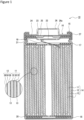
- FIG. 1 is an axial sectional view of a cylindrical secondary battery 10 of an example of an embodiment.
- an electrode assembly 14 and a non-aqueous electrolyte (not illustrated) are housed in an exterior 15.
- the electrode assembly 14 has a wound structure in which a positive electrode 11 and a negative electrode 12 are wound with a separator 13 interposed therebetween.
- a sealing assembly 16 side will be described as the "upper side”
- the bottom side of the exterior 15 will be described as the "lower side”.
- An opening end of the upper part of the exterior 15 is capped with the sealing assembly 16 to seal inside the secondary battery 10.
- Insulating plates 17 and 18 are provided on the upper and lower sides of the electrode assembly 14, respectively.
- a positive electrode lead 19 extends upward through a through hole of the insulating plate 17, and is welded to the lower face of a filter 22, which is a bottom plate of the sealing assembly 16.
- a negative electrode lead 20 extends through an outside of the insulating plate 18 toward the bottom side of the exterior 15, and is welded to a bottom inner face of the exterior 15. In the secondary battery 10, the exterior 15 becomes a negative electrode terminal.
- the exterior 15 is, for example, a bottomed cylindrical metallic exterior housing can.
- a gasket 27 is provided between the exterior 15 and the sealing assembly 16 to achieve sealability inside the secondary battery 10.
- the exterior 15 has a groove 21 formed by, for example, pressing the side wall thereof from the outside to support the sealing assembly 16.
- the groove 21 is preferably formed in a circular shape along a circumferential direction of the exterior 15, and supports the sealing assembly 16 with the gasket 27 interposed therebetween and with the upper face of the groove 21.
- the sealing assembly 16 has the filter 22, a lower vent member 23, an insulating member 24, an upper vent member 25, and the cap 26 that are stacked in this order from the electrode assembly 14 side.
- Each member constituting the sealing assembly 16 has, for example, a disk shape or a ring shape, and each member except for the insulating member 24 is electrically connected each other.
- the lower vent member 23 and the upper vent member 25 are connected each other at each of centers thereof, and the insulating member 24 is interposed between each of the circumference of the vent members 23 and 25. If the internal pressure of the battery increases due to abnormal heat generation, for example, the lower vent member 23 breaks and thereby the upper vent member 25 expands toward the cap 26 side to be separated from the lower vent member 23, resulting in cutting off of an electrical connection between both members. If the internal pressure further increases, the upper vent member 25 breaks, and gas is discharged through an opening 26a of the cap 26.
- the positive electrode 11, the negative electrode 12, the separator 13, and the non-aqueous electrolyte, which constitute the secondary battery 10, particularly a negative electrode active material included in a negative electrode mixture layer constituting the negative electrode 12, will be described in detail.
- the positive electrode 11 has a band-shaped positive electrode current collector and a positive electrode mixture layer formed on a surface of the positive electrode current collector. As illustrated in FIG. 1 , the positive electrode 11 may have the positive electrode mixture layers 32 on both surfaces of the positive electrode current collector 30.
- a foil of a metal stable within a potential range of the positive electrode 11, such as aluminum, a film in which such a metal is disposed on a surface layer thereof, and the like may be used.
- the positive electrode mixture layer 32 may include, for example, a positive electrode active material, a binder, a conductive agent, and the like.
- the positive electrode 11 may be produced by, for example, applying a positive electrode mixture slurry including the positive electrode active material, the conductive agent, the binder, and the like onto the positive electrode current collector 30, followed by drying and then compressing to form the positive electrode mixture layer 32.
- the positive electrode active material examples include a lithium-transition metal composite oxide containing a transition metal element such as Co, Mn, and Ni.
- the lithium-transition metal composite oxide examples include Li x CoO 2 , Li x NiO 2 , Li x MnO 2 , Li x Co y Ni 1-y O 2 , Li x Co y M 1-y O z , Li x Ni 1-y M y O z , Li x Mn 2 O 4 , Li x Mn 2-y M y O 4 , LiMPO 4 , and Li 2 MPO 4 F, wherein M represents at least one of Na, Mg, Sc, Y, Mn, Fe, Co, Ni, Cu, Zn, Al, Cr, Pb, Sb, and B, 0 ⁇ x ⁇ 1.2, 0 ⁇ y ⁇ 0.9, and 2.0 ⁇ z ⁇ 2.3.
- the positive electrode active material preferably includes a lithium-nickel composite oxide such as Li x NiO 2 , Li x Co y Ni 1-y O 2 , and Li x Ni 1-y MyO z , wherein M represents at least one of Na, Mg, Sc, Y, Mn, Fe, Co, Ni, Cu, Zn, Al, Cr, Pb, Sb, and B, 0 ⁇ x ⁇ 1.2, 0 ⁇ y ⁇ 0.9, and 2.0 ⁇ z ⁇ 2.3.
- inorganic compound particles such as aluminum oxide and a lanthanoid-containing compound may adhere.
- Examples of the conductive agent included in the positive electrode mixture layer 32 include carbon materials such as carbon black (CB), acetylene black (AB), Ketjenblack, and graphite. These materials may be used singly, and may be used in combination of two or more thereof.
- binder included in the positive electrode mixture layer 32 examples include fluororesins such as polytetrafluoroethylene (PTFE) and polyvinylidene fluoride (PVdF), polyacrylonitrile (PAN), a polyimide (PI), an acrylic resin, and a polyolefin resin. These materials may be used singly, and may be used in combination of two or more thereof. These resins may be used in combination with carboxymethylcellulose (CMC) or a salt thereof, polyethylene oxide (PEO), and the like.
- PTFE polytetrafluoroethylene
- PVdF polyvinylidene fluoride
- PAN polyacrylonitrile
- PI polyimide
- acrylic resin an acrylic resin
- polyolefin resin examples include polyolefin resin. These materials may be used singly, and may be used in combination of two or more thereof. These resins may be used in combination with carboxymethylcellulose (CMC) or a salt thereof, polyethylene oxide (PEO), and the like.
- the negative electrode 12 has a band-shaped negative electrode current collector and a negative electrode mixture layer formed on a surface of the negative electrode current collector. As illustrated in FIG. 1 , the negative electrode 12 may have the negative electrode mixture layers 36 on both surfaces of the negative electrode current collector 34.
- a foil of a metal stable within a potential range of the negative electrode 12, such as copper, a film in which such a metal is disposed on a surface layer, and the like may be used.
- the negative electrode mixture layer 36 may include, for example, a negative electrode active material, a binder, and the like.
- fluororesins such as PTFE and PVdF, PAN, PI, an acrylic resin, a polyolefin resin, and the like may be used similar to that in the positive electrode 11, but styrene-butadiene rubber (SBR) is preferably used.
- the negative electrode mixture layer may include CMC or a salt thereof, polyacrylic acid (PAA) or a salt thereof, polyvinyl alcohol (PVA), and the like.
- the negative electrode mixture layer 36 includes, as the negative electrode active material, a first Si-based active material 40 and a second Si-based active material 50 as exemplified in FIG. 2 (hereinafter, the first Si-based active material and the second Si-based active material may be collectively referred to as the Si-based active material).
- the first Si-based active material 40 includes at least an oxide phase 42 and Si particles 44, and has a structure in which the Si particles 44 are dispersed in the oxide phase 42.
- the first Si-based active material 40 may further include a conductive coating 48 covering surfaces of base particles 46 composed of the oxide phase 42 and the Si particles 44.
- the second Si-based active material 50 includes at least an oxide phase 52 and Si particles 54, and has a structure in which the Si particles 54 are dispersed in the oxide phase 52.
- the second Si-based active material 50 may further include a conductive coating 58 covering surfaces of base particles 56 composed of the oxide phase 52 and the Si particles 54.
- the Si particles 44 and 54 may be substantially uniformly dispersed in the oxide phases 42 and 52, respectively. That is, the base particles 46 and 56 have a sea-island structure in which the fine Si particles 44 and 54 are dispersed in the oxide phases 42 and 52, respectively.
- the Si particles 44 and 54 may be scatteringly present substantially uniformly on any cross section without uneven distribution in a part thereof.
- Average particle diameters of the Si particles 44 and 54 are preferably 200 nm or less, and more preferably 100 nm or less.
- the average particle diameters of the Si particles 44 and 54 are measured by observing a cross section of the negative electrode mixture layer by using a scanning electron microscope (SEM) or a transmission electron microscope (TEM). Specifically, the average particle diameters are determined by measuring diameters of circumscribed circles of random 100 particles selected from SEM or TEM images to average the measured value.
- the oxide phases 42 and 52 may contain a metal oxide containing at least Si as a main component (component at the most mass).
- the oxide phases 42 and 52 may be constituted by aggregation of finer particles than the Si particles 44 and 54.
- the oxide phases 42 and 52 may contain, for example, at least one of Li, Si, Al, and B.
- the oxide phases 42 and 52 may contain at least one of lithium silicate and silicon oxide as the main component.
- the lithium silicate is preferably represented by, for example, Li 2z SiO (2+z) (0 ⁇ z ⁇ 2).
- a content of the main component is preferably more than 50 mass%, more preferably 80 mass% or more, and may be substantially 100 mass%, based on the total mass of the oxide phases 42 and 52.
- the silicon oxide may be, for example, silicon dioxide (SiO 2 ).
- SiO 2 silicon dioxide
- the Si-based active materials 40 and 50 have, for example, a structure in which the Si particles 44 and 54 are dispersed in an amorphous SiO 2 matrix, and represented by SiO x (0.5 ⁇ x ⁇ 1.5).
- SiO 2 changes into mainly Li 4 SiO 4 with the first charge.
- the oxide phases 42 and 52 before the first charge may be both the lithium silicate phase or may be both the silicon oxide phase; however, preferably, the oxide phase 42 contains lithium silicate as the main component and the oxide phase 52 contains silicon oxide as the main component. That is, the first Si-based active material 40 is of preferably particles in which the Si particles 44 are dispersed in the lithium silicate phase, and the second Si-based active material 50 is of preferably particles in which the Si particles 54 are dispersed in the silicon oxide phase. In this case, the effect of improving the charge-discharge cycle characteristics of the battery becomes more remarkable.
- a content rate of the Si particles 44 in the first Si-based active material 40 is larger than a content rate of the Si particles 54 in the second Si-based active material 50.
- the content rate of the Si particles 44 in the first Si-based active material 40 means a proportion of a mass of the Si particles 44 to a mass of the base particles 46, and is preferably 40 mass% to 70 mass%, and more preferably 40 mass% to 60 mass%.
- the content rate of the Si particles 54 in the second Si-based active material 50 means a proportion of a mass of the Si particles 54 to a mass of the base particles 56, and is preferably 20 mass% to 40 mass%, and more preferably 25 mass% to 35 mass%.
- the content rate of the Si particles 44 in the first Si-based active material 40 may be 40 mass% or more, and the content rate of the Si particles 54 in the second Si-based active material 50 may be less than 40 mass%.
- the Si-based active materials 40 and 50 may be composed of only the base particles 46 and 56, respectively, and may have the conductive coatings 48 and 58 composed of a material having higher conductivity than the oxide phases 42 and 52 on the surfaces of the base particles 46 and 56, respectively.
- the conductive material constituting the conductive coatings 48 and 58 may be, for example, at least one selected from the group consisting of a carbon material, a metal, and a metal compound, and a carbon material is preferably used.
- Examples of a method for carbon-coating the surfaces of the base particles 46 and 56 include: a CVD method using acetylene, methane, and the like; and a method of mixing a coal pitch, petroleum pitch, a phenol resin and the like with the base particles 46 and 56 to be heat-treated.
- a conductive agent such as carbon black and Ketjenblack may be adhered to the surfaces of the base particles 46 and 56 using a binder to form the carbon coating layer.
- the conductive coatings 48 and 58 may be formed with covering substantially the entire regions of the surfaces of the base particles 46 and 56. Thicknesses of the conductive coatings 48 and 58 are preferably 1 nm to 200 nm, and more preferably 5 nm to 100 nm with considering achievement of the conductivity and dispersity of lithium ions toward the base particles 46 and 56. If the conductive coatings 48 and 58 are excessively thin, the conductivity is lowered, and uniformly covering the base particles 46 and 56 becomes difficult. Meanwhile, if the conductive coatings 48 and 58 are excessively thick, the dispersion of lithium ions toward the base particles 46 and 56 is inhibited to tend to decrease the capacity. The thicknesses of the conductive coatings 48 and 58 may be measured by observing a cross section of the particles using an SEM or a TEM.
- a median diameter (D50) on a volumetric basis of the first Si-based active material 40 and a D50 of the second Si-based active material 50 may be, for example, 2 ⁇ m to 20 ⁇ m.
- the median diameter (D50) on a volumetric basis also referred to as a 50% particle diameter or a median diameter, means a particle diameter at which a volumetric integrated value is 50% in a particle size distribution measured by a laser diffraction scattering method.
- the D50 of the first Si-based active material 40 may be larger than the D50 of the second Si-based active material 50.
- the D50 of the first Si-based active material 40 is preferably 7 ⁇ m to 20 ⁇ m, and more preferably 8 ⁇ m to 15 ⁇ m.
- the D50 of the second Si-based active material 50 is preferably 2 ⁇ m to 7 ⁇ m, and more preferably 3 ⁇ m to 6 ⁇ m.
- the D50s of the Si-based active materials 40 and 50 may be smaller than a D50 of a carbon-based active material, described later.
- the Si-based active materials 40 and 50 may be produced via, for example, the following steps 1 to 3.
- the Si-based active materials 40 and 50 can intercalate more lithium ions than the carbon-based active material does, the Si-based active materials 40 and 50 may be used for the negative electrode active material to increase the battery capacity. Since the Si-based active materials 40 and 50 have larger change in volume with charge and discharge than the carbon-based active material, the carbon-based active material and the Si-based active materials 40 and 50 are preferably used in combination.
- graphite conventionally used for negative electrode active materials such as: a natural graphite such as flake graphite, massive graphite, and amorphous graphite; and an artificial graphite such as massive artificial graphite (MAG) and meso-carbon microbead (MCMB) may be used, for example.
- a D50 of the graphite may be, for example 18 ⁇ m to 24 ⁇ m.
- Contents of the Si-based active materials 40 and 50 are preferably 2 mass% to 20 mass%, more preferably 3 mass% to 15 mass%, and particularly preferably 4 mass% to 10 mass%, based on the total mass of the negative electrode active material. That is, a mixing ratio between the carbon-based active material and the Si-based active material is preferably 98:2 to 80:20, more preferably 97:3 to 85:15, and particularly preferably 96:4 to 90:10, at a mass ratio. When the mass ratio between the carbon-based active material and the Si-based active materials 40 and 50 is within the above range, the charge-discharge cycle characteristics are more remarkably improved easily with increasing the capacity.
- FIG. 3 is a front view of the negative electrode 12 of an example of an embodiment.
- End parts 34a are regions at both ends in the width direction of the band-shaped negative electrode current collector 34, and a central part 34b is a central region in the width direction of the negative electrode current collector.
- a ratio of a length in the width direction (hereinafter, referred to as the width) between one end part 34a, the central part 34b, and the other end part 34a may be, for example, 1:8:1 to 3:4:3.
- a proportion of a mass of the first Si-based active material 40 to a total mass of the first Si-based active material 40 and the second Si-based active material 50 is larger in the central part 34b than in the end part 34a. This allows the central part 34b, which has a lower negative electrode potential than the end part 34a due to repeated charges and discharges, to have a large amount of the first Si-based active material 40, leading to reduction of the charge-discharge depth of the first Si-based active material 40 for inhibiting a side reaction to improve the charge-discharge cycle characteristics.
- the first Si-based active material 40 with a higher content of the Si particles 44 is advantageous to the higher capacity, the expansion and contraction thereof are large during the charge and discharge, and the side reaction is likely to occur on the surface.
- the charge and discharge expand and contract the negative electrode 12 to repeatedly cause infiltration and ooze of the electrolyte liquid, and to cause concentration gradient of lithium ions in the electrolyte liquid along the width direction of the negative electrode current collector 34 inside the electrode assembly 14, leading to a higher concentration of lithium ions in the electrolyte liquid in the central part 34b than in the end part 34a.
- This concentration gradient of lithium ions rises the negative electrode potential during the charge and discharge in the end part 34a and lowers that in the central part 34b.
- disposing a large amount of the first Si-based active material 40 in the central part 34b where the side reaction hardly occurs may achieve both the higher capacity and the charge-discharge cycle characteristics.
- the above negative electrode 12 may be produced via, for example, the following steps 1 to 3.
- a porous sheet having an ion permeation property and an insulation property may be used.
- the porous sheet include a fine porous thin film, a woven fabric, and a nonwoven fabric.
- a polyolefin such as polyethylene and polypropylene, cellulose, and the like are preferable.
- the separator 13 may have any of a single-layered structure and a stacked structure. A heat-resistant layer and the like may be formed on a surface of the separator 13.
- the non-aqueous electrolyte may include a non-aqueous solvent and an electrolyte salt dissolved in the non-aqueous solvent.
- an electrolyte salt dissolved in the non-aqueous solvent.
- esters, ethers, nitriles such as acetonitrile, amides such as dimethylformamide, a mixed solvent of two or more thereof, and the like may be used, for example.
- the non-aqueous solvent may contain a halogen-substituted derivative in which hydrogen of these solvents is at least partially substituted with a halogen atom such as fluorine.
- halogen-substituted derivative examples include fluorinated cyclic carbonates such as fluoroethylene carbonate (FEC), fluorinated chain carbonates, and fluorinated chain carboxylates such as methyl fluoropropionate (FMP).
- FEC fluoroethylene carbonate
- FMP fluorinated chain carboxylates
- esters examples include cyclic carbonates such as ethylene carbonate (EC), propylene carbonate (PC), and butylene carbonate; chain carbonates such as dimethyl carbonate (DMC), ethyl methyl carbonate (EMC), diethyl carbonate (DEC), methyl propyl carbonate, ethyl propyl carbonate, and methyl isopropyl carbonate; cyclic carboxylates such as ⁇ -butyrolactone (GBL) and ⁇ -valerolactone (GVL); and chain carboxylates such as methyl acetate, ethyl acetate, propyl acetate, methyl propionate (MP), and ethyl propionate.
- cyclic carbonates such as ethylene carbonate (EC), propylene carbonate (PC), and butylene carbonate
- chain carbonates such as dimethyl carbonate (DMC), ethyl methyl carbonate (EMC), diethyl carbonate (DEC), methyl propyl
- ethers examples include cyclic ethers such as 1,3-dioxolane, 4-methyl-1,3-dioxolane, tetrahydrofuran, 2-methyltetrahydrofuran, propylene oxide, 1,2-butylene oxide, 1,3-dioxane, 1,4-dioxane, 1,3,5-trioxane, furan, 2-methylfuran, 1,8-cineole, and a crown ether; and chain ethers such as 1,2-dimethoxyethane, diethyl ether, dipropyl ether, diisopropyl ether, dibutyl ether, dihexyl ether, ethyl vinyl ether, butyl vinyl ether, methyl phenyl ether, ethyl phenyl ether, butyl phenyl ether, pentyl phenyl ether, methoxytoluene, benzyl ethyl ether, 1,
- the electrolyte salt is preferably a lithium salt.
- the lithium salt include LiBF 4 , LiClO 4 , LiPF 6 , LiAsF 6 , LiSbF 6 , LiAlCl 4 , LiSCN, LiCF 3 SO 3 , LiCF 3 CO 2 , Li(P(C 2 O 4 )F 4 ), LiPF 6-x (C n F 2n+1 ) x (1 ⁇ x ⁇ 6, and n represents 1 or 2), LiB 10 Cl 10 , LiCl, LiBr, LiI, lithium chloroborane, a lithium lower aliphatic carboxylate, borate salts such as Li 2 B 4 O 7 and Li(B(C 2 O 4 )F 2 ), and imide salts such as LiN(SO 2 CF 3 ) 2 and LiN(C 1 F 2l+1 SO 2 )(C m F 2m+1 SO 2 ) ⁇ 1 and m represent integers of 0 or more ⁇ .
- the lithium salts may be used singly, and a plurality of types thereof may be mixed to be used. Among them, LiPF 6 is preferably used from the viewpoints of ion conductivity, electrochemical stability, and the like.
- a concentration of the lithium salt may be, for example, 0.8 mol to 1.8 mol per litter of the non-aqueous solvent.
- the positive electrode active material a lithium nickelate containing cobalt and aluminum, represented by LiNi 0.91 Co 0.045 Al 0.045 O 2 , was used.
- This positive electrode active material, acetylene black (AB), and polyvinylidene fluoride (PVdF) were mixed at a mass ratio of 100:0.75:0.6 to prepare a positive electrode mixture slurry with N-methyl-2-pyrrolidone (NMP) as a dispersion medium.
- NMP N-methyl-2-pyrrolidone
- This positive electrode mixture slurry was applied on both surfaces of a band-shaped positive electrode current collector made of aluminum foil with a doctor blade method, the coating film was dried and then compressed with a roller to form positive electrode mixture layers on both surfaces of the positive electrode current collector.
- the positive electrode current collector on which the positive electrode mixture layers were formed was cut to a predetermined electrode size to produce a positive electrode.
- Si particles 3N, crushed product with 10 ⁇ m
- lithium silicate particles represented by Li 2z SiO (2+z) (0 ⁇ z ⁇ 2) (crushed product with 10 ⁇ m) were mixed so that a content rate of the Si particles was 52 mass%, and the mixture was crush-treated with a ball mill.
- the mixed powder was taken out in an inert atmosphere, and heat-treated under a condition under an inert atmosphere at 600°C for 4 hours.
- the heat-treated powder (hereinafter, referred to as the base particles) was crushed with a jet mill, and then mixed with coal pitch for heat-treating under a condition under an inert atmosphere at 800°C for 5 hours to form a conductive coating of carbon on surfaces of the base particles.
- the amount of coating with carbon was 2 mass% based on a total mass of the particles including the base particles and the conductive coating.
- the particles on which the conductive coating was formed was disintegrated and classified by using a sieve to obtain a first Si-based active material in which the Si particles were dispersed at a content rate of 52 mass% in a lithium silicate phase, and having a D50 of 11 ⁇ m.
- Si particles 3N, crushed product with 10 ⁇ m
- silicon dioxide particles crushed product with 10 ⁇ m
- the mixed powder was taken out in an inert atmosphere, and heat-treated under a condition under an inert atmosphere at 600°C for 4 hours.
- the heat-treated powder (hereinafter, referred to as the base particles) was crushed with a jet mill, and then a conductive coating of carbon was formed on surfaces of the base particles with a CVD method (1000°C).
- the amount of coating with carbon was 5 mass% based on a total mass of the particles including the base particles and the conductive coating.
- the particles on which the conductive coating was formed was disintegrated and classified by using a sieve to obtain a second Si-based active material in which the Si particles were dispersed at a content rate of 30 mass% in a silicon dioxide phase, and having a D50 of 5 ⁇ m.
- a cross section of the particle of the Si-based active material was observed with an SEM, and it was consequently confirmed that the Si particles were substantially uniformly dispersed in the oxide phase in both of the Si-based active materials.
- the Si particles had an average particle diameter of less than 50 nm.
- the amount of coating with carbon was analyzed with a CS analyzer.
- the D50 of the Si-based active material was measured by using a laser diffraction-type particle size distribution measuring device (SALD-2000A, manufactured by SHIMADZU CORPORATION). The measurement was performed by using water as a dispersion medium, and a refractive index of the particles was set to be 1.70-0.01i.
- Graphite having a D50 of 22 ⁇ m and the above first Si-based active material were mixed at a mass ratio of 91.7:8.3 to be used as a negative electrode active material A.
- the negative electrode active material A carboxymethylcellulose (CMC), polyacrylic acid (PAA), and styrene-butadiene rubber (SBR) were mixed at a mass ratio of 100:1:1:1 to prepare a negative electrode mixture slurry A with water as a dispersion medium.
- Graphite having a D50 of 22 ⁇ m and the above second Si-based active material were mixed at a mass ratio of 96.2:3.8 to be used as a negative electrode active material B.
- a negative electrode mixture slurry B was prepared in the same manner as of the negative electrode mixture slurry A except that the negative electrode active material B was used instead of the negative electrode active material A.
- a negative electrode current collector made of copper foil was prepared, and an end part, a central part, and an end part were defined at a length ratio of 2:6:2 in the width direction.
- the negative electrode mixture slurry A was applied with a doctor blade method, the coating film was dried, then the negative electrode mixture slurry B was applied on both the end parts with a doctor blade method, the coating film was dried, and compressed with a roller to form negative electrode mixture layers on both surfaces of the negative electrode current collector.
- the negative electrode current collector on which the negative electrode mixture layers were formed was cut to a predetermined electrode size to produce a negative electrode.
- LiPF 6 was dissolved at a concentration of 1.3 mol/L. Furthermore, vinylene carbonate (VC) was dissolved into the above mixed solvent at a concentration of 4 mass% to prepare a non-aqueous electrolyte (electrolyte liquid).
- An aluminum lead was attached to the positive electrode, a nickel lead was attached to the negative electrode, the positive electrode and the negative electrode were spirally wound with a separator made of polyethylene fine porous film interposed therebetween to produce a wound electrode assembly.
- This electrode assembly was housed in an exterior, and the nickel lead was welded with a bottom of the exterior. Then, the aluminum lead was welded with a sealing assembly, the above non-aqueous electrolyte was injected thereinto, and then an opening of the exterior was sealed with the sealing assembly to obtain a non-aqueous electrolyte secondary battery.
- the negative electrode graphite, the first Si-based active material, and the second Si-based active material were mixed at a mass ratio of 93.5:5:1.5 to be used as a negative electrode active material C.
- a negative electrode was produced and a non-aqueous electrolyte secondary battery was produced in the same manner as in Example except that the negative electrode active material C was used instead of the negative electrode active material A to prepare a negative electrode mixture slurry C, and that the negative electrode mixture slurry C was applied on the entire surface of the central part and both the end parts of the negative electrode current collector to form the negative electrode mixture layer.
- graphite and the second Si-based active material were mixed at a mass ratio of 97.5:2.5 to be used as a negative electrode active material D, and graphite and the first Si-based active material were mixed at a mass ratio of 87.5: 12.5 to be used as a negative electrode active material E.
- a negative electrode was produced and a non-aqueous electrolyte secondary battery was produced in the same manner as in Example except that the negative electrode active material D was used instead of the negative electrode active material A to prepare a negative electrode mixture slurry D, and that the negative electrode active material E was used instead of the negative electrode active material B to prepare a negative electrode mixture slurry E.
- graphite and the second Si-based active material were mixed at a mass ratio of 94:6 to be used as a negative electrode active material F.
- a negative electrode was produced and a non-aqueous electrolyte secondary battery was produced in the same manner as in Example except that the negative electrode active material F was used instead of the negative electrode active material A to prepare a negative electrode mixture slurry F, and that the negative electrode mixture slurry F was applied on the entire surface of the central part and both the end parts of the negative electrode current collector to form the negative electrode mixture layer.
- each of the batteries of Example and Comparative Examples was charged at a constant current of 0.3 C until a battery voltage reached 4.2 V, charged at a constant voltage of 4.2 V until a current value reached 1/50 C, and then discharged at a constant current of 0.5 C until the battery voltage reached 2.85 V.
- a discharge capacity at this time was specified as the initial discharge capacity.
- each of the batteries of Example and Comparative Examples was charged at a constant current of 0.3 C until a battery voltage reached 4.2 V, then charged at a constant voltage of 4.2 V until a current value reached 1/50 C, and thereafter discharged at a constant current of 0.5 C until the battery voltage reached 2.85 V.
- This was set as one charge-discharge cycle.
- a charge-discharge efficiency which was a ratio of a discharge capacity to a charge capacity, was calculated in every cycle, and the number of cycles when the charge-discharge efficiencies were less than 99.8% in consecutive five cycles was specified as the number of cycles at which a discharge capacity plummeted.
- Table 1 Composition of negative electrode mixture layer (mass ratio) Evaluation results Average (graphite / lithium silicate / silicon oxide) Central part (graphite / lithium silicate / silicon oxide) End part (graphite / lithium silicate / silicon oxide) Initial discharge capacity [mAh] Number of cycles at which discharge capacity plummets Example 93.5/5/1.5 91.7/8.3/0 96.2/0/3.8 3348 100 Comparative Example 1 93.5/5/1.5 3348 50 Comparative Example 2 93.5/5/1.5 97.5/0/2.5 87.5/12.5/0 3348 30 Comparative Example 3 94/0/6 3250 100
- the battery of Example has excellent charge-discharge cycle characteristics compared with the batteries of Comparative Examples 1 and 2, and exhibits higher capacity than Comparative Example 3.
- the batteries of Comparative Examples 1 to 3 have insufficient one of the battery capacity and the charge-discharge cycle characteristics; on the other hand, only the battery of Example achieves both the battery capacity and the charge-discharge cycle characteristics. That is, required for the achievement of both the battery capacity and the charge-discharge cycle characteristics is not only merely mixing to use the two kinds of the Si-based active materials having different content rates of the Si particles (the first Si-based active material and the second Si-based active material) but also appropriately dispersing each thereof in the negative electrode mixture layer.
Landscapes
- Chemical & Material Sciences (AREA)
- Chemical Kinetics & Catalysis (AREA)
- Electrochemistry (AREA)
- General Chemical & Material Sciences (AREA)
- Engineering & Computer Science (AREA)
- Materials Engineering (AREA)
- Composite Materials (AREA)
- Inorganic Chemistry (AREA)
- Manufacturing & Machinery (AREA)
- Crystallography & Structural Chemistry (AREA)
- Battery Electrode And Active Subsutance (AREA)
Applications Claiming Priority (2)
| Application Number | Priority Date | Filing Date | Title |
|---|---|---|---|
| JP2020109746 | 2020-06-25 | ||
| PCT/JP2021/022950 WO2021261358A1 (fr) | 2020-06-25 | 2021-06-16 | Électrode négative pour batterie secondaire à électrolyte non aqueux et batterie secondaire à électrolyte non aqueux |
Publications (2)
| Publication Number | Publication Date |
|---|---|
| EP4174982A1 true EP4174982A1 (fr) | 2023-05-03 |
| EP4174982A4 EP4174982A4 (fr) | 2024-03-27 |
Family
ID=79281334
Family Applications (1)
| Application Number | Title | Priority Date | Filing Date |
|---|---|---|---|
| EP21830205.7A Pending EP4174982A4 (fr) | 2020-06-25 | 2021-06-16 | Électrode négative pour batterie secondaire à électrolyte non aqueux et batterie secondaire à électrolyte non aqueux |
Country Status (5)
| Country | Link |
|---|---|
| US (1) | US20230246178A1 (fr) |
| EP (1) | EP4174982A4 (fr) |
| JP (1) | JP7638280B2 (fr) |
| CN (1) | CN115917782B (fr) |
| WO (1) | WO2021261358A1 (fr) |
Family Cites Families (11)
| Publication number | Priority date | Publication date | Assignee | Title |
|---|---|---|---|---|
| JP5103789B2 (ja) * | 2006-05-24 | 2012-12-19 | パナソニック株式会社 | リチウム二次電池用負極およびそれを用いたリチウム二次電池 |
| JP2015230747A (ja) * | 2014-06-03 | 2015-12-21 | トヨタ自動車株式会社 | リチウムイオン二次電池用電極 |
| US10177403B2 (en) * | 2015-02-23 | 2019-01-08 | Sanyo Electric Co., Ltd. | Negative-electrode active material for non-aqueous electrolyte secondary battery, negative electrode for non-aqueous electrolyte secondary battery, and non-aqueous electrolyte secondary battery |
| JP6609946B2 (ja) * | 2015-03-18 | 2019-11-27 | 凸版印刷株式会社 | リチウムイオン二次電池用電極、その製造方法及びリチウムイオン二次電池 |
| JP6119796B2 (ja) * | 2015-05-14 | 2017-04-26 | 信越化学工業株式会社 | 非水電解質二次電池用負極活物質、及びそれを用いた非水電解質二次電池 |
| JP7015447B2 (ja) * | 2017-11-14 | 2022-02-03 | 株式会社Gsユアサ | 非水電解質二次電池 |
| CN111602275B (zh) | 2018-01-19 | 2023-06-09 | 三洋电机株式会社 | 非水电解质二次电池 |
| JP6699689B2 (ja) * | 2018-06-27 | 2020-05-27 | トヨタ自動車株式会社 | 負極の製造方法、負極および非水電解液二次電池 |
| JP6683221B2 (ja) * | 2018-07-26 | 2020-04-15 | トヨタ自動車株式会社 | 負極、非水電解液二次電池、および負極の製造方法 |
| EP3859828B1 (fr) * | 2018-09-26 | 2023-04-05 | Panasonic Intellectual Property Management Co., Ltd. | Électrode négative de batterie secondaire à électrolyte non aqueux, et batterie secondaire à électrolyte non aqueux |
| DE102020111241A1 (de) * | 2020-04-24 | 2021-10-28 | Bayerische Motoren Werke Aktiengesellschaft | Anode, Lithiumionenbatterie und Verfahren zum Herstellen einer Anode |
-
2021
- 2021-06-16 CN CN202180044731.4A patent/CN115917782B/zh active Active
- 2021-06-16 US US18/011,444 patent/US20230246178A1/en active Pending
- 2021-06-16 EP EP21830205.7A patent/EP4174982A4/fr active Pending
- 2021-06-16 WO PCT/JP2021/022950 patent/WO2021261358A1/fr not_active Ceased
- 2021-06-16 JP JP2022531890A patent/JP7638280B2/ja active Active
Also Published As
| Publication number | Publication date |
|---|---|
| EP4174982A4 (fr) | 2024-03-27 |
| JP7638280B2 (ja) | 2025-03-03 |
| US20230246178A1 (en) | 2023-08-03 |
| CN115917782A (zh) | 2023-04-04 |
| JPWO2021261358A1 (fr) | 2021-12-30 |
| WO2021261358A1 (fr) | 2021-12-30 |
| CN115917782B (zh) | 2025-07-29 |
Similar Documents
| Publication | Publication Date | Title |
|---|---|---|
| EP4207355B1 (fr) | Électrode positive pour batteries secondaires à électrolyte non aqueux, et batterie secondaire à électrolyte non aqueux | |
| CN110212196B (zh) | 非水电解质二次电池和非水电解质二次电池的制造方法 | |
| EP4209461A1 (fr) | Matériau actif d'électrode positive pour batteries secondaires à électrolyte non aqueux, et batterie secondaire à électrolyte non aqueux | |
| JP2019040701A (ja) | 非水電解質二次電池 | |
| EP4485558A1 (fr) | Électrode positive pour batteries secondaires à électrolyte non aqueux et batterie secondaire à électrolyte non aqueux | |
| EP4224561A1 (fr) | Électrode négative pour batteries secondaires et batterie secondaire | |
| EP4224560A1 (fr) | Électrode négative pour batterie secondaire et batterie secondaire | |
| WO2016151979A1 (fr) | Electrode négative pour batteries secondaires à électrolyte non aqueux et batterie secondaire à électrolyte non aqueux | |
| EP4411853A1 (fr) | Batterie secondaire à électrolyte non aqueux | |
| EP4270528A1 (fr) | Électrode positive pour batterie secondaire à électrolyte non aqueux, et batterie secondaire à électrolyte non aqueux | |
| EP4224554A1 (fr) | Batterie secondaire à électrolyte non aqueux | |
| US20250140786A1 (en) | Non-aqueous electrolyte secondary battery | |
| EP4411861A1 (fr) | Batterie rechargeable à électrolyte non aqueux | |
| EP4328992A1 (fr) | Batterie secondaire à électrolyte non aqueux | |
| WO2019171761A1 (fr) | Électrode positive de batterie secondaire, collecteur de courant d'électrode positive de batterie secondaire et batterie secondaire | |
| EP4138157A1 (fr) | Matériau actif d'électrode positive pour batteries secondaires à électrolyte non aqueux, et batterie secondaire à électrolyte non aqueux | |
| EP4270520A1 (fr) | Matériau actif d'électrode positive pour batteries secondaires à électrolyte non aqueux, et batterie secondaire à électrolyte non aqueux | |
| EP4160717A1 (fr) | Électrode positive de batterie secondaire à électrolyte non aqueux, et batterie secondaire à électrolyte non aqueux | |
| EP4174982A1 (fr) | Électrode négative pour batterie secondaire à électrolyte non aqueux et batterie secondaire à électrolyte non aqueux | |
| EP4517877A1 (fr) | Matériau actif d'électrode négative pour batterie secondaire à électrolyte non aqueux, et batterie secondaire à électrolyte non aqueux | |
| EP4459714A1 (fr) | Matériau actif d'électrode positive pour batterie secondaire à électrolyte non aqueux et batterie secondaire à électrolyte non aqueux | |
| US20250192234A1 (en) | Non-aqueous electrolyte secondary battery | |
| EP4456165A1 (fr) | Électrode négative pour batteries secondaires à électrolyte non aqueux, et batterie secondaire à électrolyte non aqueux | |
| EP4489129A1 (fr) | Matériau actif d'électrode positive pour batterie secondaire à électrolyte non aqueux et batterie secondaire à électrolyte non aqueux | |
| US20250266441A1 (en) | Non-aqueous electrolyte secondary battery |
Legal Events
| Date | Code | Title | Description |
|---|---|---|---|
| STAA | Information on the status of an ep patent application or granted ep patent |
Free format text: STATUS: THE INTERNATIONAL PUBLICATION HAS BEEN MADE |
|
| PUAI | Public reference made under article 153(3) epc to a published international application that has entered the european phase |
Free format text: ORIGINAL CODE: 0009012 |
|
| STAA | Information on the status of an ep patent application or granted ep patent |
Free format text: STATUS: REQUEST FOR EXAMINATION WAS MADE |
|
| 17P | Request for examination filed |
Effective date: 20221215 |
|
| AK | Designated contracting states |
Kind code of ref document: A1 Designated state(s): AL AT BE BG CH CY CZ DE DK EE ES FI FR GB GR HR HU IE IS IT LI LT LU LV MC MK MT NL NO PL PT RO RS SE SI SK SM TR |
|
| DAV | Request for validation of the european patent (deleted) | ||
| DAX | Request for extension of the european patent (deleted) | ||
| A4 | Supplementary search report drawn up and despatched |
Effective date: 20240226 |
|
| RIC1 | Information provided on ipc code assigned before grant |
Ipc: H01M 4/02 20060101ALI20240220BHEP Ipc: H01M 10/052 20100101ALI20240220BHEP Ipc: H01M 4/58 20100101ALI20240220BHEP Ipc: H01M 4/48 20100101ALI20240220BHEP Ipc: H01M 4/1395 20100101ALI20240220BHEP Ipc: H01M 4/131 20100101ALI20240220BHEP Ipc: H01M 4/13 20100101ALI20240220BHEP Ipc: H01M 4/38 20060101ALI20240220BHEP Ipc: H01M 4/36 20060101ALI20240220BHEP Ipc: H01M 4/134 20100101AFI20240220BHEP |