EP4174985A1 - Batterie au plomb de type liquide - Google Patents
Batterie au plomb de type liquide Download PDFInfo
- Publication number
- EP4174985A1 EP4174985A1 EP21832652.8A EP21832652A EP4174985A1 EP 4174985 A1 EP4174985 A1 EP 4174985A1 EP 21832652 A EP21832652 A EP 21832652A EP 4174985 A1 EP4174985 A1 EP 4174985A1
- Authority
- EP
- European Patent Office
- Prior art keywords
- positive electrode
- bones
- bone
- vertical
- frame bone
- Prior art date
- Legal status (The legal status is an assumption and is not a legal conclusion. Google has not performed a legal analysis and makes no representation as to the accuracy of the status listed.)
- Withdrawn
Links
Images


Classifications
-
- H—ELECTRICITY
- H01—ELECTRIC ELEMENTS
- H01M—PROCESSES OR MEANS, e.g. BATTERIES, FOR THE DIRECT CONVERSION OF CHEMICAL ENERGY INTO ELECTRICAL ENERGY
- H01M10/00—Secondary cells; Manufacture thereof
- H01M10/04—Construction or manufacture in general
- H01M10/0486—Frames for plates or membranes
-
- H—ELECTRICITY
- H01—ELECTRIC ELEMENTS
- H01M—PROCESSES OR MEANS, e.g. BATTERIES, FOR THE DIRECT CONVERSION OF CHEMICAL ENERGY INTO ELECTRICAL ENERGY
- H01M10/00—Secondary cells; Manufacture thereof
- H01M10/06—Lead-acid accumulators
-
- H—ELECTRICITY
- H01—ELECTRIC ELEMENTS
- H01M—PROCESSES OR MEANS, e.g. BATTERIES, FOR THE DIRECT CONVERSION OF CHEMICAL ENERGY INTO ELECTRICAL ENERGY
- H01M10/00—Secondary cells; Manufacture thereof
- H01M10/06—Lead-acid accumulators
- H01M10/08—Selection of materials as electrolytes
-
- H—ELECTRICITY
- H01—ELECTRIC ELEMENTS
- H01M—PROCESSES OR MEANS, e.g. BATTERIES, FOR THE DIRECT CONVERSION OF CHEMICAL ENERGY INTO ELECTRICAL ENERGY
- H01M10/00—Secondary cells; Manufacture thereof
- H01M10/06—Lead-acid accumulators
- H01M10/12—Construction or manufacture
-
- H—ELECTRICITY
- H01—ELECTRIC ELEMENTS
- H01M—PROCESSES OR MEANS, e.g. BATTERIES, FOR THE DIRECT CONVERSION OF CHEMICAL ENERGY INTO ELECTRICAL ENERGY
- H01M4/00—Electrodes
- H01M4/02—Electrodes composed of, or comprising, active material
- H01M4/14—Electrodes for lead-acid accumulators
-
- H—ELECTRICITY
- H01—ELECTRIC ELEMENTS
- H01M—PROCESSES OR MEANS, e.g. BATTERIES, FOR THE DIRECT CONVERSION OF CHEMICAL ENERGY INTO ELECTRICAL ENERGY
- H01M4/00—Electrodes
- H01M4/02—Electrodes composed of, or comprising, active material
- H01M4/14—Electrodes for lead-acid accumulators
- H01M4/16—Processes of manufacture
- H01M4/20—Processes of manufacture of pasted electrodes
-
- H—ELECTRICITY
- H01—ELECTRIC ELEMENTS
- H01M—PROCESSES OR MEANS, e.g. BATTERIES, FOR THE DIRECT CONVERSION OF CHEMICAL ENERGY INTO ELECTRICAL ENERGY
- H01M4/00—Electrodes
- H01M4/02—Electrodes composed of, or comprising, active material
- H01M4/36—Selection of substances as active materials, active masses, active liquids
- H01M4/48—Selection of substances as active materials, active masses, active liquids of inorganic oxides or hydroxides
-
- H—ELECTRICITY
- H01—ELECTRIC ELEMENTS
- H01M—PROCESSES OR MEANS, e.g. BATTERIES, FOR THE DIRECT CONVERSION OF CHEMICAL ENERGY INTO ELECTRICAL ENERGY
- H01M4/00—Electrodes
- H01M4/02—Electrodes composed of, or comprising, active material
- H01M4/64—Carriers or collectors
- H01M4/66—Selection of materials
- H01M4/68—Selection of materials for use in lead-acid accumulators
- H01M4/685—Lead alloys
-
- H—ELECTRICITY
- H01—ELECTRIC ELEMENTS
- H01M—PROCESSES OR MEANS, e.g. BATTERIES, FOR THE DIRECT CONVERSION OF CHEMICAL ENERGY INTO ELECTRICAL ENERGY
- H01M4/00—Electrodes
- H01M4/02—Electrodes composed of, or comprising, active material
- H01M4/64—Carriers or collectors
- H01M4/70—Carriers or collectors characterised by shape or form
- H01M4/72—Grids
- H01M4/73—Grids for lead-acid accumulators, e.g. frame plates
-
- H—ELECTRICITY
- H01—ELECTRIC ELEMENTS
- H01M—PROCESSES OR MEANS, e.g. BATTERIES, FOR THE DIRECT CONVERSION OF CHEMICAL ENERGY INTO ELECTRICAL ENERGY
- H01M4/00—Electrodes
- H01M4/02—Electrodes composed of, or comprising, active material
- H01M4/64—Carriers or collectors
- H01M4/70—Carriers or collectors characterised by shape or form
- H01M4/72—Grids
- H01M4/74—Meshes or woven material; Expanded metal
-
- H—ELECTRICITY
- H01—ELECTRIC ELEMENTS
- H01M—PROCESSES OR MEANS, e.g. BATTERIES, FOR THE DIRECT CONVERSION OF CHEMICAL ENERGY INTO ELECTRICAL ENERGY
- H01M50/00—Constructional details or processes of manufacture of the non-active parts of electrochemical cells other than fuel cells, e.g. hybrid cells
- H01M50/50—Current conducting connections for cells or batteries
- H01M50/531—Electrode connections inside a battery casing
- H01M50/54—Connection of several leads or tabs of plate-like electrode stacks, e.g. electrode pole straps or bridges
- H01M50/541—Connection of several leads or tabs of plate-like electrode stacks, e.g. electrode pole straps or bridges for lead-acid accumulators
-
- Y—GENERAL TAGGING OF NEW TECHNOLOGICAL DEVELOPMENTS; GENERAL TAGGING OF CROSS-SECTIONAL TECHNOLOGIES SPANNING OVER SEVERAL SECTIONS OF THE IPC; TECHNICAL SUBJECTS COVERED BY FORMER USPC CROSS-REFERENCE ART COLLECTIONS [XRACs] AND DIGESTS
- Y02—TECHNOLOGIES OR APPLICATIONS FOR MITIGATION OR ADAPTATION AGAINST CLIMATE CHANGE
- Y02E—REDUCTION OF GREENHOUSE GAS [GHG] EMISSIONS, RELATED TO ENERGY GENERATION, TRANSMISSION OR DISTRIBUTION
- Y02E60/00—Enabling technologies; Technologies with a potential or indirect contribution to GHG emissions mitigation
- Y02E60/10—Energy storage using batteries
-
- Y—GENERAL TAGGING OF NEW TECHNOLOGICAL DEVELOPMENTS; GENERAL TAGGING OF CROSS-SECTIONAL TECHNOLOGIES SPANNING OVER SEVERAL SECTIONS OF THE IPC; TECHNICAL SUBJECTS COVERED BY FORMER USPC CROSS-REFERENCE ART COLLECTIONS [XRACs] AND DIGESTS
- Y02—TECHNOLOGIES OR APPLICATIONS FOR MITIGATION OR ADAPTATION AGAINST CLIMATE CHANGE
- Y02P—CLIMATE CHANGE MITIGATION TECHNOLOGIES IN THE PRODUCTION OR PROCESSING OF GOODS
- Y02P70/00—Climate change mitigation technologies in the production process for final industrial or consumer products
- Y02P70/50—Manufacturing or production processes characterised by the final manufactured product
Definitions
- the present invention relates to a liquid-type lead storage battery.
- ISS vehicles vehicles mounted with an idling stop system
- the ISS vehicles stop the engine when stop at a traffic light or the like to suppress fuel consumption, and therefore can improve fuel efficiency and further can reduce the emission amount.
- the lead storage battery mounted in the ISS vehicles described above tends to have a short life.
- the reasons therefor are as follows.
- the lead storage battery is used up to a deep discharge depth to supply power to equipment, such as air conditioners, lights, wipers, and car navigation systems, when the engine stops due to the stop at a traffic light, for example. Further, the discharge for restarting the engine in starting and the charge by an alternator or a regenerative brake are repeated. Due to these severe uses, the lead storage battery is seriously damaged particularly in power generation elements.
- an electrode plate group serving as the power generation element has a laminate containing a plurality of positive electrode plates and negative electrode plates arranged alternately and separators arranged between the positive electrode plates and the negative electrode plates.
- the positive electrode plate has a positive electrode current collector and a positive electrode mixture containing a positive electrode active material.
- the positive electrode active material contains lead dioxide.
- the positive electrode current collector has a rectangular grid substrate and a lug (also referred to as a "current collecting lug") continuous to the grid substrate. The positive electrode mixture is held in the grid substrate.
- the lugs of the plurality of positive electrode plates are connected with a positive electrode strap.
- the negative electrode plate has a negative current collector and a negative electrode mixture containing a negative electrode active material.
- the negative electrode active material contains metallic lead.
- the negative current collector has a rectangular grid substrate and a lug continuous to the grid substrate. The negative electrode mixture is held in the grid substrate. The lugs of the plurality of negative electrode plates are connected with a negative electrode strap.
- the positive electrode current collector and the negative current collector mainly contain lead or a lead alloy.
- An example of the grid substrate includes a grid substrate structured to have frame bones forming the four sides of the rectangle and a plurality of intermediate bones connected to the frame bones and present inside the frame bones.
- the frame bones have an upper frame bone located on the upper side of the grid substrate and extending in the lateral direction, a lower grid substrate located on the lower side of the grid substrate and extending in the lateral direction, and a pair of vertical frame bones extending in the vertical direction.
- the lug projects upward from a position shifted to the side close to either one of the pair of vertical frame bones from the longitudinal center of the upper frame bone.
- the plurality of intermediate bones has a plurality of vertical intermediate bones from the upper frame bone toward the lower frame bone side or from the lower frame bone toward the upper frame bone side and a plurality of lateral intermediate bones from one of the pair of vertical frame bones toward the side of the other one of the pair of vertical frame bones or from the other one of the pair of vertical frame bones toward the side of the one of the pair of vertical frame bones.
- spaces surrounded by the frame bones and the plurality of intermediate bones or spaces surrounded only by the plurality of intermediate bones are present as opening portions.
- the positive electrode mixture is charged at least into the opening portions of the grid substrate of the positive electrode current collector.
- the negative electrode mixture is charged at least into the opening portions of the grid substrate of the negative current collector.
- a battery case of the liquid-type lead storage battery is a box type having an opening portion in the upper side and has a plurality of cell chambers for housing the electrode plate groups. The plurality of cell chambers is separated by partitions. The opening portion of the battery case is sealed with a lid.
- a metal component for example, a bushing
- the lid has a communication port (also referred to as a "liquid port") for injecting an electrolyte.
- the positions and the number of the liquid ports correspond to the positions and the number of the cell chambers of the battery case.
- the battery case and the lid are formed of acid-resistant resins. Examples of the acid-resistant resins include polypropylene, polyester, and ABS.
- additives such as aluminum sulphate, are sometimes added to the electrolyte according to performance demanded in the liquid-type lead storage battery.
- the growth is a phenomenon in which a positive electrode grid body (grid substrate of the positive electrode current collector) entirely expands or is deformed due to corrosion of the positive electrode grid body.
- the occurrence of the growth poses a risk that the positive electrode grid body is partially curved and broken, and the broken end breaks through the separators to contact the opposing negative electrode plate or expands upward to, for example, contact a part of the negative electrode, such as the negative electrode strap, causing an internal short circuit.
- the deformation of the positive electrode grid body causes peeling off or dropping of the positive electrode mixture, which also causes an early capacity decrease.
- the mechanism by which the growth occurs is considered as follows.
- the corrosion of the positive electrode grid body in the lead storage batteries, not limited to the liquid type is caused by an oxidation reaction in which the lead or the lead alloy forming the positive electrode grid body reacts with sulfate ions contained mainly in the electrolyte or the positive electrode mixture and changes into a multilayered corrosion reaction product containing PbO x (x: 1 to 2), PbSO 4 , or the like.
- This corrosion proceeds mainly by the repeated charge and discharge.
- the growth of a layer of the corrosion reaction product is remarkable.
- the growth of the corrosion reaction product generates a force of pulling and expanding the surface of the positive electrode grid body.
- the lead alloy in a center portion away from the surface tends to resist the deformation of the surface. Therefore, as the corrosion proceeds, complicated stresses are generated, and the deformation starts preferentially from a portion where a difference between the stresses is remarkable. As a result, the positive electrode grid body entirely expands, resulting in the growth.
- a potential distribution of the positive electrode grid body is closely related to the incidence of the corrosion.
- a current path is longer than that in the other parts, and therefore the DC resistance increases based on the Ohm's law. Therefore, the polarization in the extraction of a current is small in the vicinity of the lug and large in the opposite corner area.
- the closer it is to the lug the more likely it is that a large current flows through the positive electrode grid body and that the corrosion proceeds.
- the active material present in the vicinity of the lug is preferentially used for a charge/discharge reaction, and therefore deterioration, such as softening or dropping, of the positive electrode mixture is likely to proceed.
- the potential distribution greatly changes depending on the shape or the arrangement of the vertical intermediate bones and the lateral intermediate bones.
- a potential difference between the vicinity of the lug and the opposite corner area increases as the vertical intermediate bones approach the vertical state or the lateral intermediate bones approach the horizontal state.
- the potential difference between the vicinity of the lug and the opposite corner area increases.
- the positive electrode grid body having a simple grid shape in which all the vertical intermediate bones and the lateral intermediate bones are orthogonal to each other has posed a problem that a difference in the proceed of the deterioration among sites in plan view is likely to be large, and the life is likely to be shortened due to the equilibrium.
- PTL 1 and PTL 2 disclose grid for liquid-type lead storage batteries which do not have a simple grid shape.
- the projecting position of a lug is a position shifted to the right side from the longitudinal center of an upper frame bone, and all vertical intermediate bones are arranged along a diagonal line starting from a certain point on a line extending the center line in the width direction of the lug upward and ending at a lower frame bone or right and left vertical frame bones.
- the vertical intermediate bones each present on the right side and the left side relative to the above-described reference line have the starting point of the diagonal line located at the upper side as the connection point with the upper frame of each vertical intermediate bone is separated from the lug.
- the resistance is smaller than that in the case of a simple grid shape, so that the in-plane potential distribution is improved.
- the area of an opening portion increases with an increase in the distance from the lug, and therefore, when vibration or impact is applied during in-vehicle use, the active material is likely to drop, and the discharge capacity is reduced corresponding to the amount of the dropping material, so that the life is likely to be shortened.
- vertical intermediate bones on the side close to a lug extends perpendicularly to an upper frame bone and a lower frame bone
- the other vertical intermediate bones extend radially (along a plurality of lines spreading from one point) to spread diagonally from the side of a lower frame bone of an opposite corner area toward the side of an upper frame or toward the side of perpendicularly extending vertical intermediate bones.
- the grid body has seven radially spreading vertical intermediate bones, four of which are directly connected to the upper frame bone and the remaining three of which are directly connected to the perpendicularly extending vertical intermediate bone.
- liquid-type lead storage battery having the grid body of such a shape
- a large current is concentrated on the perpendicularly extending vertical intermediate bones close to the lug based on the Kirchhoff's first law.
- the corrosion rapidly proceeds and the resistance increases in the perpendicularly extending vertical intermediate bones, and then, when the corrosion further proceeds, the vertical intermediate bones may be broken or raptured.
- a current extracted from the radially spreading vertical intermediate bones decreases, which may cause a sharp decrease in battery performance.
- PTL 3 discloses that, to prevent upward accelerated growth, horizontal bars (lateral intermediate bones) having a large cross-sectional area are arranged in an upper part region of a frame bone on the side opposite to a position where a positive electrode current collecting lug is connected of a first lateral frame bone (upper frame bone).
- a first aspect of the present invention provided to solve the above-described problems is a liquid-type lead storage battery having the following configurations (1) to (4).
- the average value A is the average value of the cross-sectional areas of all the lateral intermediate bones including the thick lateral intermediate bone.
- the "positive electrode current collector is formed of a lead alloy having a rolled structure” can be obtained by, for example, applying punching processing or expanding processing to a rolled plate obtained by rolling a lead alloy slab with a multistage rolling mill until a predetermined thickness is reached.
- the lateral intermediate bones sometime have a uniform cross-sectional area in the longitudinal direction of the lateral intermediate bone or sometimes has a cross-sectional area changed in the longitudinal direction, such as a cross-sectional area becoming smaller toward a center part from at least either one of the right frame bone and the left frame bone extending in the vertical direction.
- the ratio B/A is calculated using the minimum cross-sectional area value.
- a second aspect of the present invention provided to solve the above-described problems is a liquid-type lead storage battery having the configurations (1) to (3) above and the following configurations (5) and (6).
- the liquid-type lead storage battery has a plurality of first vertical intermediate bones which is the vertical intermediate bone extending diagonally from each position of the upper frame bone toward the lower frame bone side to be separated from the position directly under the lug of the lower frame bone and a second vertical intermediate bone which is the vertical intermediate bone arranged closest to a first vertical frame bone which is the vertical frame bone on the side far from the lug and reaching the lower frame bone.
- An angle ⁇ L formed by a straight line indicating the direction in which the second vertical intermediate bone extends and a straight line indicating the direction in which the first vertical frame bone extends is -10° or more and 10° or less.
- the positive/negative of the angle ⁇ L is defined as "negative” when the second vertical intermediate bone is directed toward the vertical frame bone (second vertical frame bone) on the side close to the lug and is defined as "positive” when the second vertical intermediate bone is directed toward the first vertical frame bone, as the second vertical intermediate bone is directed from the upper frame bone toward the lower frame bone.
- the growth in the lateral direction is likely to be larger than the growth in the vertical direction.
- the right and left frame bones of the expanding positive electrode plate sometimes stretch and tear the contacting separators, resulting in that the positive electrodes and the negative electrodes laminated on each other via the separators form a contact short circuit, so that the end of life is reached at an early stage.
- the separators are not torn, a part of the positive electrode grid body broken by corrosion breaks through the separators, resulting in a contact short circuit with the negative electrode plate, so that the end of life is reached at an early stage in some cases.
- a current collector formed of a lead alloy having a rolled structure (for example, obtained by applying punching processing or expanding processing to a rolled plate of a lead alloy) has a rolled structure containing a fine fibrous crystal structure in which crystal grains containing the lead alloy are oriented in a fixed direction. Therefore, the growth caused by corrosion is likely to proceed.
- a current collector obtained by casting a lead alloy (cast plate) has a coarse granular crystal structure, and the grain boundaries are preferentially corroded, and therefore the growth is difficult to proceed.
- a large difference in the growth speed is largely affected by the crystal structure (small grain boundaries with active dislocation movement promote creep), and therefore the growth is likely to considerably proceed in the rolled plate as compared with the cast plate.
- a grid substrate formed by a casting method or a punching method generally has frame bones thicker than right and left frame bones on the upper side and the lower side, and therefore an upper part and a lower part have high mechanical strength, and are less likely to undergo the elongation in the lateral direction than the elongation in the vertical direction.
- the inside of the frame bones particularly the vicinity of a center part in the up-down direction is provided with intermediate bones relatively thin with respect to the frame bones and is far from the upper and lower frame bones, and therefore lacks mechanical strength as compared with the upper part and the lower part of the grid substrate.
- a barrel-shaped deformation is observed in which the changes in the upper part and the lower part are small and the changes in the center part is large in the lateral direction.
- the barrel-shaped deformation occurs more remarkably in the laterally long positive electrode grid body than in the vertically long positive electrode grid body.
- the deformation of the positive electrode grid body is not limited to the center part, and the lower part having mechanical strength lower than that of the upper part is deformed, and the form of the positive electrode grid body is changed from the barrel shape to a mountain shape.
- Such a deformation into the mountain shape is a new problem to be solved found by the examination of the present inventors and the like on the liquid-type lead storage battery having a life prolonged by suppressing an upper part short circuit by the invention described in PTL 3.
- the positive electrode grid body is designed to exhibit a uniform potential distribution such that the positive electrode active material is used from the upper part to the lower part during charge and discharge.
- a technology is adopted which includes providing a plurality of intermediate bones for reinforcement in the upper part of the positive electrode grid body, for example, for reducing the area of the opening portion in the vicinity of the current collecting lug and increasing the current collection efficiency of the positive electrode active material.
- the intermediate bones for reinforcement are not provided in the lower part of the positive electrode grid body in many cases.
- the density of the intermediate bones is high, so that the mechanical strength is larger than that of the lower part.
- the horizontal bars (lateral intermediate bones) having a large cross-sectional area are arranged in the upper part region of the frame bone on the side opposite to the position where the positive electrode current collecting lug is connected of the first lateral frame bone (upper frame bone) to prevent the upward accelerated growth, so that the difference in the mechanical strength between the upper part and the lower part of the positive electrode grid body is larger.
- the long use of the positive electrode plate having the laterally long grid substrate poses a risk that the grid substrate is deformed into the barrel shape, causing the tearing in the lateral direction of the separators, and forming a contact short circuit with the negative electrode plate.
- the lead storage battery according to the first aspect of the present invention has the above-described configuration (4) in the lead storage battery having the above-described configurations (1) to (3). More specifically, at least one of the plurality of lateral intermediate bones is the thick lateral intermediate bone having the cross-sectional area B larger than the average value A of the cross-sectional areas of the plurality of lateral intermediate bones. Due to the fact that the cross-sectional area ratio B/A is 1.15 or more, the mechanical strength of the positive electrode plate is improved, and thus the positive electrode grid body is difficult to elongate in the lateral direction, so that the deformation of the positive electrode grid body (grid substrate of the positive electrode current collector) into the barrel shape or the mountain shape can be suppressed.
- the installation of at least one thick lateral intermediate bone below a center part in the vertical direction of the positive electrode grid body where the lateral elongation is likely to occur, for example, in the positive electrode grid body improves the mechanical strength, which makes it difficult to cause the elongation in the lateral direction, so that the deformation into the barrel shape or the mountain shape of the positive electrode grid body can be suppressed.
- the peeling off or the dropping of the active material is suppressed, so that the decrease in the discharge capacity is suppressed and, further, a short life due to corrosion of the grid substrate due to the entrance of the electrolyte into a place where the peeling off or the dropping of the active material has occurred and the accelerated growth can also be prevented.
- one aspect of the present invention provides a lead storage battery with a long life because the growth caused by the corrosion of the grid substrate is suppressed in the positive electrode current collector containing the rolled plate, and therefore a short circuit due to a contact between the positive electrode plate and the negative electrode plate is suppressed.
- the cross-sectional area ratio B/A is preferably set to 1.25 or less.
- the vertical intermediate bones are arranged to extend diagonally from respective positions of the upper frame bone toward the lower frame bone side to be separated from the position directly under the lug of the lower frame bone, and the lug projects upward from the position shifted to the side close to the right frame bone from the longitudinal center of the upper frame bone, the deformation of the left frame bone (first vertical frame bone which is the vertical frame bone on the side far from the lug) promotes the peeling off or the dropping of the positive electrode mixture.
- a particular focus should be placed on the peeling off or the dropping of the positive electrode mixture charged into the plurality of opening portions adjacent to the left frame bone.
- the positive electrode mixture charged into the plurality of opening portions adjacent to the left frame bone is referred to as a left end positive electrode mixture.
- the opening portions filled with the left end positive electrode mixture are referred to as left end opening portions.
- the vertical intermediate bone forming the left end opening portions is referred to as a left end vertical bone (vertical intermediate bone farthest from the lug). More specifically, the left end vertical bone in this case is the vertical intermediate bone arranged closest to the left frame bone (first vertical frame bone).
- the left end positive electrode mixture is in close contact with the left frame bone like cement, and has actions of preventing contact between the left frame bone and the electrolyte and stopping the deformation, such as elongation or curvature, of the left frame bone. Therefore, when the left end positive electrode mixture is peeled off from the left frame bone or is dropped from the left end opening portions, surface corrosion of the left frame bone is not prevented, so that the above-described accelerated growth proceeds. The once peeled-off left end positive electrode mixture does not have the power to stop the deformation of the relevant left frame bone.
- the left end positive electrode mixture is more likely to be peeled off/dropped as the opening area of the left end opening portions in plan view is larger. This is because the contact area with the positive electrode grid body per unit volume of the positive electrode mixture decreases.
- the more the lead storage battery is operated in the partial state of charge for a case, such as a case where the lead storage battery is mounted in the ISS vehicles the more the left end positive electrode mixture is softened, and therefore the left end positive electrode mixture is more likely to be peeled off/dropped.
- vibration applied from the outside during in-vehicle use easily peels off/drops the softened positive electrode mixture.
- the peeling off or the dropping of the charged positive electrode mixture is particularly likely to occur in the left end opening portions, which can cause a shorter life of the liquid-type lead storage battery used in the partial state of charge as in the ISS vehicles.
- a liquid-type lead storage battery according to a second aspect of the present invention has the above-described configurations (5) and (6) in the lead storage battery having the above-described configurations (1) to (4). More specifically, it has been found that, by setting the angle ⁇ L to -10° or more and 10° or less, even when the lead storage battery is used over a long time in the partial state of charge, the peeling off or the dropping of the positive electrode mixture ("left end positive electrode mixture" described above) arranged in the opening portions ("left end opening portions” described above ) is significantly suppressed, the opening portions being formed by the first vertical frame bone (vertical frame bone on the side far from the lug), the second vertical intermediate bone (vertical intermediate bone arranged closest to the first vertical frame bone and reaching the lower frame bone described above), and the pair of lateral intermediate bones (or the lateral intermediate bones and the upper frame bone or the lower frame bone).
- the angle ⁇ L is preferably -5° to 5° and more preferably -2° to 3°.
- the growth of the first vertical frame bone ("left frame bone” described above) of the positive electrode grid body proceeds in an accelerated manner due to the peeling off or the dropping of the left end positive electrode mixture charged into the left end opening portions. Then, the proceed of the accelerated growth causes the deformation of the left frame bone or the vertical intermediate bones around the left frame bone and accelerates the peeling off or the dropping of the left end positive electrode mixture. Therefore, it can be said that the way of delaying "the first occurrence of the peeling off or the dropping of the left end positive electrode mixture” is the key to prevent the peeling off or the dropping of the left end positive electrode mixture and prolong the life of the liquid-type lead storage battery.
- an area difference among the plurality of left end opening portions in the up-down direction becomes smaller in plan view.
- the area difference among the opening portions has a positive correlation with the likelihood of the peeling off or the dropping of the positive electrode mixture charged into the opening portions. More specifically, by reducing the area difference among the plurality of left end opening portions in the up-down direction, the first occurrence of the peeling off or the dropping of the left end positive electrode mixture can be delayed.
- a minimum separation distance d L between the first vertical frame bone and the second vertical intermediate bone is 5.0 mm or more and 10.0 mm or less.
- the opening area of the left end opening portions is excessively small, it is necessary to increase the pressurizing force in a pressurizing step using a pressurizing roller or the like in a step of charging a positive electrode paste into the positive electrode grid body.
- the distance d L is 5.0 mm or more and 10.0 mm or less, the left end opening portions have an opening area suitable for paste charging, and therefore the manufacturing cost can be reduced.
- the range where the distance d L is 5.0 mm or more and 10.0 mm or less is a numerical value range particularly suitable for the fluidity of the positive electrode paste of a liquid-type lead storage battery for the ISS vehicles.
- Embodiments of the present invention are described.
- the embodiments described below give examples of the present invention, and the present invention is not limited to the embodiments.
- the embodiments can be variously altered or modified, and aspects to which such alternations or modifications are added can also be included in the present invention.
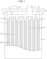
- Liquid-type lead storage batteries of a first embodiment, a second embodiment, and a third embodiment include an electrode plate group 1 in which a plurality of positive electrode plates 10 and negative electrode plates 20 are alternately laminated via ribbed separators 30 as illustrated in FIG. 1 .
- the electrode plate group 1 is housed in a cell chamber of a battery case 41 together with an electrolyte (not illustrated) such that the laminating direction is along the horizontal direction (i.e., the plate surfaces of the positive electrode plates 10 and the negative electrode plates 20 are along the perpendicular direction) and immersed in the electrolyte in the cell chamber of the battery case 41.
- the liquid-type lead storage batteries include the electrode plate group 1 and the battery case 41 having the cell chamber housing the electrode plate group 1 together with the electrolyte, in which one electrode plate group 1 is housed in one cell chamber and the number of the positive electrode plates 10 constituting the electrode plate group 1 is equal to or less than the number of the negative electrode plates 20.
- the positive electrode plate 10 has a positive electrode current collector and a positive electrode mixture containing a positive electrode active material, and the positive electrode active material contains lead dioxide.
- the positive electrode current collector has a rectangular grid substrate and a lug 11 continuous to the grid substrate, and the positive electrode mixture is held in the grid substrate.
- the negative electrode plate 20 has a negative current collector and a negative electrode mixture containing a negative electrode active material, and the negative electrode active material contains metallic lead.
- the negative current collector has a rectangular grid substrate and a lug 21 continuous to the grid substrate, and the negative electrode mixture is held in the grid substrate.
- the positive electrode mixture and the negative electrode mixture are charged into opening portions of the corresponding grid substrates and are present as mixture layers on both the plate surfaces of the grid substrates.
- the positive electrode current collector is described in detail below.
- the negative current collector constituting the negative electrode plate 20 is formed by a punching method to a lead alloy rolled plate. Examples of manufacturing methods other than the punching method for the positive electrode current collector and the negative current collector include a lead alloy casting method and an expanding method using a lead alloy rolled plate.
- the separator 30 is a porous film-like body containing resin, glass, or the like, for example, and has a flat plate-shaped base surface and, as necessary, pleated ribs projecting in a direction orthogonal to the plane direction of the base surface.
- the lugs 11 of the plurality of positive electrode plates 10 are connected with a positive electrode strap 13.
- the lugs 21 of the plurality of negative electrode plates 20 are connected with a negative electrode strap 23.
- the positive electrode strap 13 is connected to one end of a positive electrode terminal 15, the negative electrode strap 23 is connected to one end of a negative electrode terminal 25, and the other end of the positive electrode terminal 15 and the other end of the negative electrode terminal 25 penetrate a lid 43 closing an opening portion of the battery case 41 to be exposed to the outside of a case body of the liquid-type lead storage battery including the battery case 41 and the lid 43.
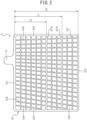
- a positive electrode current collector 5 constituting the positive electrode plate 10 of the first embodiment is formed by punching processing to a lead alloy rolled plate and has a laterally long rectangular grid substrate 51 and the lug 11 continuous to the grid substrate, and the positive electrode mixture is held in the grid substrate 51.
- the positive electrode current collector 5 a stripe-like rolled structure is observed on the cut surface perpendicular to the plate surface. In such a rolled structure, metal crystals in the lead alloy are stretched into a thin layer shape by rolling.
- the positive electrode current collector 5 is formed of the lead alloy having the rolled structure.
- the grid substrate 51 has frame bones forming the four sides of the rectangle and a plurality of intermediate bones connected to the frame bones and present inside the frame bones.
- the frame bones include an upper frame bone 511 located on the upper side of the grid substrate and extending in the lateral direction, a lower frame bone 512 located on the lower side of the grid substrate and extending in the lateral direction, a left frame bone 513 located on the left side of the grid substrate and extending in the vertical direction, and a right frame bone 514 located on the right side of the grid substrate and extending in the vertical direction.
- the lug 11 projects upward from a position shifted to the right frame bone 514 side from the longitudinal center of the upper frame bone 511.
- the plurality of intermediate bones includes a plurality of vertical intermediate bones 516 from respective positions of the upper frame bone 511 toward the lower frame bone 512 side and a plurality of lateral intermediate bones 517 connecting the left frame bone 513 and the right frame bone 514.
- all the vertical intermediate bones 516 are arranged along a diagonal line starting from a certain point on a reference line obtained by extending, upward, a line extending perpendicularly to the lower frame bone 512 on the right side relative to the lug and ending at the lower frame bone 512 or the lateral intermediate bone 517.
- the vertical intermediate bones present on the right side and the left side relative to the reference line each have the starting point of the diagonal line located on the upper side as the connection points with the upper frame of the vertical intermediate bones are separated from the lug.
- a current path from an opposite corner area to the lug is shorter than that of a positive electrode grid body having a simple grid shape.
- Two of the plurality of lateral intermediate bones 517 are thick lateral intermediate bones 517a, 517b having a cross-sectional area B larger than an average value A of the cross-sectional areas of the plurality of lateral intermediate bones 517, and a cross-sectional area ratio B/A is 1.15 or more.
- the distance between the center position in the vertical direction of the upper frame bone and the center position in the vertical direction of the lower frame bone is defined as L0 and the distance between the center position in the vertical direction of the upper frame bone and the center position in the vertical direction of the thick lateral intermediate bone 517a is defined as L1, a ratio L1/L0 is 0.66.
- L2 the distance between the center position in the vertical direction of the upper frame bone and the center position in the vertical direction of the thick lateral intermediate bone 517b
- a ratio L2/L0 is 0.47.
- the grid substrate 51 of the positive electrode current collector 5 constituting the positive electrode plate 10 has the two thick lateral intermediate bones 517a, 517b, the thick lateral intermediate bone 517a being present in a lower half region and the thick lateral intermediate bone 517b being present in the vicinity of a center part in the vertical direction of the grid substrate 51.
- a positive electrode current collector 5 constituting a positive electrode plate 10A of a second embodiment is formed by punching processing to a lead alloy rolled plate and has a laterally long rectangular grid substrate 51 and a lug 11 continuous to the grid substrate, and a positive electrode mixture is held in the grid substrate 51.
- a stripe-like rolled structure is observed on the cut surface perpendicular to the plate surface.
- metal crystals in the lead alloy are stretched into a thin layer shape by rolling.
- the positive electrode current collector 5 is formed of the lead alloy having the rolled structure.
- the grid substrate 51 has frame bones forming the four sides of the rectangle and a plurality of intermediate bones connected to the frame bones and present inside the frame bones.
- the frame bones include an upper frame bone 511 located on the upper side of the grid substrate and extending in the lateral direction, a lower frame bone 512 located on the lower side of the grid substrate and extending in the lateral direction, a left frame bone 513 located on the left side of the grid substrate and extending in the vertical direction, and a right frame bone 514 located on the right side of the grid substrate and extending in the vertical direction.
- the lug 11 projects upward from a position shifted to the right frame bone 514 side from the longitudinal center of the upper frame bone 511.
- the plurality of intermediate bones includes a plurality of first vertical intermediate bones 516a extending diagonally from respective positions of the upper frame bone 511 toward the lower frame bone 512 side to be separated from the position directly under the lug 11 of the lower frame bone 512, a second vertical intermediate bone 518 arranged closest to the left frame bone 513 and reaching the lower frame bone, and a plurality of lateral intermediate bones 517 connecting the left frame bone 513 and the right frame bone 514.
- the plurality of first vertical intermediate bones 516a is arranged on a diagonal line starting from a certain point on a reference line obtained by extending, upward, a line extending perpendicularly to the lower frame bone 512 on the slightly right side relative to the center in the width direction of the lug and ending at the lower frame bone 512 or the lateral intermediate bone 517.
- the vertical intermediate bones present on the right side and the left side relative to the reference line each have the starting point of the diagonal line located on the upper side as the connection points with the upper frame of the vertical intermediate bones are separated from the lug.
- a current path from an opposite corner area to the lug is shorter than that of a positive electrode grid body having a simple grid shape.
- An angle ⁇ L formed by a straight line K518 indicating the direction in which the second vertical intermediate bone 518 extends and a straight line K513 indicating the direction in which the left frame bone (first vertical frame bone) 513 extends is -10° or more and 10° or less.
- a minimum separation distance d L between the left frame bone (first vertical frame bone) 513 and the second vertical intermediate bone 518 is 7.0 mm.
- the average separation distance between the adjacent lateral intermediate bones 517 is 5.5 mm.
- the average opening area of a plurality of left end opening portions 519 in plan view is 30 mm 2 or more and 104 mm 2 or less.
- Two of the plurality of lateral intermediate bones 517 are thick lateral intermediate bones 517a, 517b having a cross-sectional area B larger than an average value A of the cross-sectional areas of the plurality of lateral intermediate bones 517, and the cross-sectional area ratio B/A is 1.15 or more.
- the distance between the center position in the vertical direction of the upper frame bone and the center position in the vertical direction of the lower frame bone is defined as L0 and the distance between the center position in the vertical direction of the upper frame bone and the center position in the vertical direction of the thick lateral intermediate bone 517a is defined as L1, a ratio L1/L0 is 0.66.
- L2 the distance between the center position in the vertical direction of the upper frame bone and the center position in the vertical direction of the thick lateral intermediate bone 517b
- a ratio L2/L0 is 0.47.
- the grid substrate 51 of the positive electrode current collector 5 constituting the positive electrode plate 10A has the two thick lateral intermediate bones 517a, 517b, the thick lateral intermediate bone 517a being present in a lower half region and the thick lateral intermediate bone 517b being present in the vicinity of a center part in the vertical direction of the grid substrate 51.
- a positive electrode current collector 5B constituting a positive electrode plate 10 of a third embodiment is the same as the positive electrode current collector 5A constituting the positive electrode plate 10 according to the second embodiment, except that all lateral intermediate bones 517 have the same thickness.
- the grid substrate 51 of each of the positive electrode current collectors 5, 5A constituting the positive electrode plates 10 has the thick lateral intermediate bones 517a, 517b having the ratio B/A of 1.15 or more. Therefore, as compared with a case where all the lateral intermediate bones have the same thickness as that of the lateral intermediate bones 517, the mechanical strength of the positive electrode plate is improved and the positive electrode plate becomes difficult to elongate in the lateral direction, so that the deformation into the barrel shape or the mountain shape of the grid substrates 51 of the positive electrode current collectors 5, 5A containing a rolled plate is suppressed. Thus, the growth caused by corrosion of the grid substrate 51 is suppressed, and a short circuit due to the contact between the positive electrode plate and the negative electrode plate is prevented, so that the life is prolonged.
- the liquid-type lead storage batteries according to the second embodiment and the third embodiment have both the first vertical intermediate bone 516a and the second vertical intermediate bone 518 as the vertical intermediate bones of the grid substrates 51 of the positive electrode current collectors 5A, 5B constituting the positive electrode plates 10, and the angle ⁇ L is - 10° or more and 10° or less.
- the peeling off or the dropping of the positive electrode mixture positive electrode mixture arranged in the left end opening portions 519 is remarkably suppressed as compared with a case of having only the first vertical intermediate bone 516a.
- the left end opening portions 519 have an opening area suitable for paste charging, and therefore the manufacturing cost can be reduced.
- the vertical intermediate bones 516 of the grid substrate 51 of the positive electrode current collector 5 constituting the positive electrode plate 10 and the first vertical intermediate bone 516a of the grid substrates 51 of the positive electrode current collectors 5A, 5B constituting the positive electrode plates 10 are arranged to extend diagonally from respective positions of the upper frame bone toward the lower frame bone side to be separated from the position directly under the lug of the lower frame bone. Therefore, as compared with a liquid-type lead storage battery including a positive electrode current collector having a simple grid shape, a charge/discharge reaction accompanied by the electrolysis of the electrolyte in a lower part of the positive electrode plate 10 is likely to proceed in constant voltage charge or the like.
- liquid-type lead storage batteries according to the first embodiment to the third embodiment each have an excellent discharge capacity because the utilization rate of the positive electrode active material in the positive electrode mixture held in the lower part of the positive electrode plate increases due to the arrangement of the vertical intermediate bones 516 and the first vertical intermediate bone 516a.
- the liquid-type lead storage batteries of the first embodiment to the third embodiment are suitable as liquid-type lead storage batteries mounted in vehicles controlling the charge, such as charge control vehicles and idling stop vehicles, and mainly used in the partial state of charge.
- the partial state of charge is a state in which the charge state is more than 70% and less than 100%, for example.
- the liquid-type lead storage batteries of the first embodiment to the third embodiment are usable not only as a power source for starting the internal combustion engine of vehicles but as a motive power source or an auxiliary backup power source for electric vehicles, electric forklifts, electric buses, electric motorcycles, electric scooters, small electric mopeds, golf carts, electric locomotives, and the like. Further, the liquid-type lead storage batteries according to the embodiments are also usable as a power source for lighting and a backup power source. Alternatively, the liquid-type lead storage batteries according to the embodiments are also usable as power storage devices for electric energy generated by solar power generation, wind power generation, and the like.
- Liquid-type lead storage batteries (Samples No. 1 to No. 39) having a battery size of Q-85 were produced by the following method. As shown in Tables 1 to 3, the liquid-type lead storage batteries of the samples are different in the configuration of lateral intermediate bones of a positive electrode current collector, but are the same except for the difference.
- current collectors for positive electrode plate and negative electrode plate were produced from a Pb-Ca-Sn alloy rolled plate by a punching method. In the cross section of the current collector cut in the thickness direction, a rolled structure with an average interlayer distance of 20 um was observed.
- the liquid-type lead storage battery of Sample No. 1 is a conventional example, and the positive electrode current collector thereof does not include the thick lateral intermediate bones 517a, 517b in the positive electrode current collector 5 in FIG. 2 , and all the lateral intermediate bones 517 have the same thickness.
- the grid substrate 51 of the positive electrode current collector 5 has a width (dimension in the lateral direction) of 137 mm and a height (dimension in the vertical direction) of 116.5 mm. Both the dimensions are not the distances between the centerlines of the frame bones but the distances between the outermost sides.
- the cross-sectional areas of all the lateral intermediate bones 517 are 1.00 mm 2 .
- one of the plurality of lateral intermediate bones 517 constituting the grid substrate 51 is a thick lateral intermediate bone.
- the ratio L1/L0 of the distance (distance between the center positions in the vertical direction) L1 between the thick lateral intermediate bone and the upper frame bone 511 to the distance (distance between the center positions in the vertical direction) L0 between the upper frame bone 511 and the lower frame bone 512 is any of 0.40, 0.50, 0.60, 0.70, 0.80, and 0.90.
- the cross-sectional areas of the lateral intermediate bones other than the thick lateral intermediate bone are the same and 1.00 mm 2 .
- the average value A of the cross-sectional areas of all the lateral intermediate bones including the thick lateral intermediate bone is set to 1.01 mm 2 , 1.02 mm 2 , 1.02 mm 2 , 1.03 mm 2 , or 1.03 mm 2
- the ratio B/A is set to 1.10, 1.15, 1.20, 1.25, or 1.30.
- two of the plurality of lateral intermediate bones 517 are thick lateral intermediate bones.
- One of the two thick lateral intermediate bones is arranged at a position where the ratio L1/L0 of the distance (distance between the center positions in the vertical direction) L1 from the upper frame bone 511 to the distance (distance between the center positions in the vertical direction) L0 between the upper frame bone 511 and the lower frame bone 512 is 0.80.
- the other one is arranged at a position where the ratio L2/L0 of the distance (distance between the center positions in the vertical direction) L2 ( ⁇ L1) from the upper frame bone 511 to the distance L0 is any of 0.40, 0.50, 0.60, and 0.70.
- the cross-sectional areas of the lateral intermediate bones other than the thick lateral intermediate bones are the same and 1.00 mm 2
- the cross-sectional areas B of both the two thick lateral intermediates are 1.26 mm 2
- the average value A of the cross-sectional areas of all the lateral intermediate bones including the thick lateral intermediate bones is 1.05 mm 2 .
- the ratio B/A is 1.20.
- three of the plurality of lateral intermediate bones 517 are thick lateral intermediate bones.
- Two of the three thick lateral intermediate bones are present in a lower half region from the center part in the vertical direction of the grid substrate 51, and the remaining one is located at a position in an upper half region.
- the two thick lateral intermediate bones present in the lower half region are arranged at a position where the ratio L1/L0 is 0.80 and at a position where the ratio L2/L0 is 0.60.
- One thick lateral intermediate bone present in the upper half region is arranged at a position where the ratio L3/L0 is any of 0.10, 0.20, 0.30, and 0.40.
- the cross-sectional areas B of the three thick lateral intermediate bones are all 1.30 mm 2 .
- the cross-sectional areas of the lateral intermediate bones other than the thick lateral intermediate bones are all the same and 1.00 mm 2 .
- the average value A of the cross-sectional areas of all the lateral intermediate bones including the thick lateral intermediate bones is 1.08 mm 2 .
- the ratio B/A is 1.20.
- the average cross-sectional area thereof is defined as B and the ratio B/A is determined.
- the negative current collector one was used which had the same shape as that of the positive electrode current collector 5 illustrated in FIG. 2 and in which all the lateral intermediate bones had the same thickness.
- a lead powder containing lead monoxide as a main component was kneaded with water and dilute sulfuric acid, and, as necessary, additives were mixed and kneaded to produce a paste for positive electrode mixture.
- a ratio ⁇ /( ⁇ + ⁇ ) of a mass ⁇ of ⁇ -lead dioxide and a mass ⁇ of ⁇ -lead dioxide contained in the positive electrode active material was set to 20%.
- a lead powder containing lead monoxide as a main component was kneaded with water and dilute sulfuric acid, and, as necessary, additives were mixed and kneaded to produce a paste for negative electrode mixture.
- the paste for positive electrode mixture was charged into the grid substrate of the positive electrode current collector, and then aged and dried to produce a positive electrode plate before formation.
- the paste for negative electrode mixture was charged into the grid substrate of the negative current collector, and then aged and dried to produce a negative electrode plate before formation.
- the density of the positive electrode active material possessed by the positive electrode plate was 4.2 g/cm 3 .
- the density of the negative electrode active material possessed by the negative electrode plate was 4.0 g/cm 3 .
- a ribbed separator which contained a porous synthetic resin and had a flat plate-shaped base surface and pleated ribs projecting in a direction orthogonal to the plane direction of the base surface.
- the total thickness of the ribbed separators was set to 0.90 mm, the rib height was set to 0.65 mm, and the thickness of the base surface was set to 0.25 mm.
- the number of the positive electrode plates was set to 7.
- the number of the negative electrode plates was set to 8.
- This electrode plate group was housed in a battery case, the lugs of the positive electrode current collectors of the positive electrode plates were connected with a positive electrode strap, and the lugs of the negative current collectors of the negative electrode plates were connected with a negative electrode strap. Then, the positive electrode strap was connected to one end of a positive electrode terminal and the negative electrode strap was connected to one end of a negative electrode terminal.
- the battery case has a plurality of cell chambers housing the electrode plate group, but the volume of a portion with a level equal to or below the upper level (highest liquid level) per cell chamber is 570 cm 3 .
- the electrode plate group was loaded with a predetermined group pressure.
- an opening portion of the battery case was closed with a lid.
- a positive electrode pole and a negative electrode pole were individually caused to penetrate through a bushing insert-molded in the lid, and were welded in a state where the other end of the positive electrode pole and the other end of the negative electrode pole were exposed to the outside of a lead storage battery, so that the positive electrode terminal and the negative electrode terminal were formed.
- an electrolyte containing dilute sulfuric acid with a relative density of 1.23 and containing aluminum sulfate at a concentration of 0.1 mol/L was injected to the upper level of the battery case, the liquid port was sealed with a plug body, and then battery case formation was performed, so that a lead storage battery was obtained.
- the time from the injection of the electrolyte to the start of energization for the formation (i.e., soaking time) was set to 30 minutes, the amount of electricity for the formation was set to 230%, and the temperature of the electrolyte in the formation was set to 45°C. At this time, the amount of the injected electrolyte was 375 cm 3 per cell chamber. The relative density of the electrolyte after the formation was 1.28.
- liquid-type lead storage batteries of Samples No. 1 to No. 39 thus obtained were subjected to a combined life test at 75°C, and investigated for the number of cycles until the end of the life.
- the conditions of the life test are as follows. First, in a 75°C environment, a cycle of 300 A discharge for 2 seconds, CCCV for 60 minutes (14.5 V, maximum charge current 50 A), 25 A discharge for 5 minutes, and CCCV for 30 minutes (14.5 V, maximum charge current 50 A) was repeated a plurality of times in this order. When the voltage at each discharge dropped to 7.2 V, it was determined that the end of life was reached, and the number of cycles that had been performed up to the moment was defined as the life.
- the life test results were evaluated according to the following criteria. A case where the number of cycles is less than 360 was evaluated as “ ⁇ ”, a case where the number of cycles is 360 or more and less than 380 was evaluated as “ ⁇ ”, a case where the number of cycles is 380 or more and less than 400 was evaluated as " ⁇ ”, and a case where the number of cycles is 400 or more was evaluated as " ⁇ ".
- any of the following four states is indicated as the "Separator state" in Table 1.
- the liquid-type lead storage battery is demanded to reduce the weight, and thus is in a situation of being requested to reduce the mass by even a few grams. Therefore, the suppression of a battery weight increase was evaluated according to the following criteria.
- the mass of the positive electrode current collector in the conventional example is 48.0 g, and a case where an increased amount of the mass based on the mass is less than 0.5 g was evaluated as " ⁇ ", a case where the increased amount of the mass based on the mass is 0.5 g or more and less than 1.0 g was evaluated as " ⁇ ", a case where the increased amount of the mass based on the mass is 1.0 g or more and less than 1.5 g was evaluated as " ⁇ ”, and a case where the increased amount of the mass based on the mass is 1.5 g or more was evaluated as " ⁇ ".
- the separator state when the separator state is evaluated as " ⁇ ", it is considered that the positive electrode plate and the negative electrode plate formed a contact short circuit, so that the life was shortened.
- the separator state When the separator state was evaluated as " ⁇ ”, it is considered that the softening or the peeling off of the positive electrode active material proceeded due to an increase in distortion caused by the expansion of the positive electrode plate, which was not able to be visually confirmed.
- the separator state is evaluated as "o”, it is considered that the distortion caused by the expansion of the positive electrode plate is suppressed and the life property was improved.
- the separator state When the separator state is evaluated as " ⁇ ”, it is considered that the effect of suppressing the distortion caused by the expansion of the positive electrode plate was high and the excellent life property was obtained.
- the weight (mass) of the grid substrate of the positive electrode current collector increases. Therefore, from the viewpoint of reducing the weight of the liquid-type lead storage battery, the cross-sectional area ratio (B/A) of the lateral intermediate bone is preferably set to 1.25 or less.
- Liquid-type lead storage batteries of Samples No. 40 to No. 53 were produced by the same method as the method described in the first comparative test, except for using positive electrode current collectors of No. 40 to No. 53.
- one of the plurality of lateral intermediate bones 517 constituting the grid substrate 51 is a thick lateral intermediate bone in the positive electrode current collector 5A in FIG. 3 .
- the ratio L1/L0 of the distance (distance between the center positions in the vertical direction) L1 between the thick lateral intermediate bone and the upper frame bone 511 to the distance (distance between the center positions in the vertical direction) L0 between the upper frame bone 511 and the lower frame bone 512 is 0.70.
- the cross-sectional areas of the lateral intermediate bones other than the thick lateral intermediate bone are all the same and 1.00 mm 2 .
- the ratio B/A is set to 1.25.
- liquid-type lead storage batteries of Samples No. 40 to No. 53 are different in the configuration of the left end vertical intermediate bone 518, but are the same except for the difference.
- the distances d L of the positive electrode current collectors of Samples No. 40 to No. 48 are 7.0 mm and the same, but the angle ⁇ L of each of the positive electrode current collectors is -15°, -10°, -5°, -2°, 0°, 3°, 5°, 10°, or 15°.
- the angles ⁇ L of the positive electrode current collectors of Samples No. 49 to No. 53 are 0° and the same, but the distances d L are 3.0 mm, 5.0 mm, 8.0 mm, 10.0 mm, and 12.0 mm, respectively.
- the angles ⁇ L of the positive electrode current collectors are 0° and only the distances d L are different.
- the distance d L is preferably 5.0 mm or more and 10.0 mm or less.
- Liquid-type lead storage batteries of Samples No. 54 to No. 67 were produced by the same method as the method described in the first comparative test, except for using positive electrode current collectors of No. 54 to No. 67.
- the liquid-type lead storage batteries of Samples No. 54 to No. 67 have the positive electrode current collector 5B illustrated in FIG. 4 .
- the liquid-type lead storage batteries of Samples No. 54 to No. 67 are the same as the liquid-type lead storage battery of the first comparative test, except for the difference.
- the cross-sectional areas of the plurality of lateral intermediate bones 517 constituting the positive electrode current collector 5B were all the same and herein set to 1.00 mm 2 .
- liquid-type lead storage batteries of Samples No. 54 to No. 67 are different in the configuration of the left end vertical intermediate bone 518, but are the same except for the difference.
- the distances d L of the positive electrode current collectors of Samples No. 54 to No. 62 are 7.0 mm and the same, but the angle ⁇ L is -15°, -10°, -5°, -2°, 0°, 3°, 5°, 10°, or 15°.
- the angles ⁇ L of the positive electrode current collectors of Samples No. 63 to No. 67 are 0° and the same, but the distances d L are 3.0 mm, 5.0 mm, 8.0 mm, 10.0 mm, and 12.0 mm, respectively.
- the distances d L of the positive electrode current collectors are 7.0 mm and only the angles ⁇ L are different.
- the angle ⁇ L is set to -10° or more and 10° or less, excellent life performance of 400 cycles or more can be exhibited, and the separator state is also good.
- the angle ⁇ L is set to -5° or more and 5° or less, more excellent life performance of 405 cycles or more can be exhibited.
- the angle ⁇ L By setting the angle ⁇ L to -2° or more and 3° or less, still more excellent life performance of 408 cycles or more can be exhibited.
- the angles ⁇ L of the positive electrode current collectors are 0° and only the distances d L are different.
- the distance d L is preferably 5.0 mm or more and 10.0 mm or less.
Landscapes
- Chemical & Material Sciences (AREA)
- Chemical Kinetics & Catalysis (AREA)
- Electrochemistry (AREA)
- General Chemical & Material Sciences (AREA)
- Engineering & Computer Science (AREA)
- Manufacturing & Machinery (AREA)
- Materials Engineering (AREA)
- Inorganic Chemistry (AREA)
- Cell Electrode Carriers And Collectors (AREA)
- Battery Electrode And Active Subsutance (AREA)
- Secondary Cells (AREA)
Applications Claiming Priority (2)
| Application Number | Priority Date | Filing Date | Title |
|---|---|---|---|
| JP2020113457 | 2020-06-30 | ||
| PCT/JP2021/017267 WO2022004120A1 (fr) | 2020-06-30 | 2021-04-30 | Batterie au plomb de type liquide |
Publications (1)
| Publication Number | Publication Date |
|---|---|
| EP4174985A1 true EP4174985A1 (fr) | 2023-05-03 |
Family
ID=79315276
Family Applications (1)
| Application Number | Title | Priority Date | Filing Date |
|---|---|---|---|
| EP21832652.8A Withdrawn EP4174985A1 (fr) | 2020-06-30 | 2021-04-30 | Batterie au plomb de type liquide |
Country Status (5)
| Country | Link |
|---|---|
| US (1) | US12463257B2 (fr) |
| EP (1) | EP4174985A1 (fr) |
| JP (1) | JP7149046B2 (fr) |
| CN (1) | CN115668551B (fr) |
| WO (1) | WO2022004120A1 (fr) |
Families Citing this family (1)
| Publication number | Priority date | Publication date | Assignee | Title |
|---|---|---|---|---|
| JP7478877B1 (ja) | 2023-03-29 | 2024-05-07 | 古河電池株式会社 | 液式鉛蓄電池 |
Family Cites Families (13)
| Publication number | Priority date | Publication date | Assignee | Title |
|---|---|---|---|---|
| US4221852A (en) * | 1979-05-21 | 1980-09-09 | Esb United States, Inc. | Radial grids for lead acid batteries |
| JPH07235307A (ja) * | 1994-02-21 | 1995-09-05 | Shin Kobe Electric Mach Co Ltd | ペースト式極板用格子体ユニット |
| JP2002042821A (ja) | 2000-07-27 | 2002-02-08 | Shin Kobe Electric Mach Co Ltd | 鉛蓄電池用格子体 |
| JP4900627B2 (ja) | 2008-12-22 | 2012-03-21 | 新神戸電機株式会社 | 鉛蓄電池用格子板、極板及びこの極板を備えた鉛蓄電池 |
| JP6032130B2 (ja) * | 2013-05-31 | 2016-11-24 | 株式会社Gsユアサ | 蓄電池用格子及びこれを用いた蓄電池 |
| IN2014CH02207A (fr) * | 2013-05-31 | 2015-07-03 | Gs Yuasa Int Ltd | |
| JP6548139B2 (ja) * | 2015-01-05 | 2019-07-24 | 株式会社Gsユアサ | 制御弁式鉛蓄電池 |
| JP7024177B2 (ja) * | 2016-10-03 | 2022-02-24 | 株式会社Gsユアサ | 鉛蓄電池及び集電体 |
| US12451493B2 (en) | 2017-01-27 | 2025-10-21 | Cps Technology Holdings Llc | Battery grid |
| JP2019067522A (ja) | 2017-09-28 | 2019-04-25 | 古河電池株式会社 | 鉛蓄電池用正極格子体の製造方法、蓄電池用正極格子体、及び鉛蓄電池 |
| JP6456537B1 (ja) | 2018-02-28 | 2019-01-23 | 古河電池株式会社 | 鉛蓄電池用正極格子体及び鉛蓄電池 |
| JP6762974B2 (ja) * | 2018-02-28 | 2020-09-30 | 古河電池株式会社 | 鉛蓄電池用正極格子体及び鉛蓄電池 |
| CN210866358U (zh) * | 2019-10-25 | 2020-06-26 | 古河电池株式会社 | 液式铅蓄电池的正极集电体以及液式铅蓄电池 |
-
2021
- 2021-04-30 EP EP21832652.8A patent/EP4174985A1/fr not_active Withdrawn
- 2021-04-30 WO PCT/JP2021/017267 patent/WO2022004120A1/fr not_active Ceased
- 2021-04-30 JP JP2022525113A patent/JP7149046B2/ja active Active
- 2021-04-30 CN CN202180037053.9A patent/CN115668551B/zh active Active
- 2021-04-30 US US18/013,395 patent/US12463257B2/en active Active
Also Published As
| Publication number | Publication date |
|---|---|
| WO2022004120A1 (fr) | 2022-01-06 |
| CN115668551B (zh) | 2025-12-02 |
| JPWO2022004120A1 (fr) | 2022-01-06 |
| US20230282889A1 (en) | 2023-09-07 |
| CN115668551A (zh) | 2023-01-31 |
| JP7149046B2 (ja) | 2022-10-06 |
| US12463257B2 (en) | 2025-11-04 |
Similar Documents
| Publication | Publication Date | Title |
|---|---|---|
| CN105514504B (zh) | 铅蓄电池 | |
| EP2330676B1 (fr) | Batterie de stockage au plomb-acide | |
| EP1930978B1 (fr) | Batterie d accumulateurs au plomb et son procédé de production | |
| CN101999190A (zh) | 铅蓄电池及其制造方法 | |
| EP1717896B1 (fr) | Batterie au plomb | |
| EP4174985A1 (fr) | Batterie au plomb de type liquide | |
| CN104541394B (zh) | 铅蓄电池用板栅和铅蓄电池 | |
| CN108028436A (zh) | 铅蓄电池 | |
| EP3553870A1 (fr) | Batterie de stockage au plomb-acide | |
| JP2005302395A (ja) | 鉛蓄電池 | |
| EP4194573A1 (fr) | Alliage de plomb, électrode positive pour batterie de stockage au plomb, batterie de stockage au plomb et système de stockage d'électricité | |
| JP6762975B2 (ja) | 鉛蓄電池用正極格子体及び鉛蓄電池 | |
| JP2009266514A (ja) | 鉛蓄電池 | |
| JP7152441B2 (ja) | 液式鉛蓄電池 | |
| US7658774B2 (en) | Method of producing lattice body for lead storage battery, and lead storage battery | |
| JP2023079571A (ja) | 液式鉛蓄電池 | |
| JP4364054B2 (ja) | 鉛蓄電池 | |
| JP4529707B2 (ja) | 鉛蓄電池 | |
| EP4195333A1 (fr) | Batterie de stockage au plomb liquide | |
| CN223296952U (zh) | 端板、电池、车辆及用电设备 | |
| JP7097403B2 (ja) | 鉛蓄電池 | |
| JPH10208750A (ja) | 鉛蓄電池 | |
| JP2021163677A (ja) | 液式鉛蓄電池 | |
| JP2004273305A (ja) | 鉛蓄電池 | |
| JP2021163614A (ja) | 鉛蓄電池 |
Legal Events
| Date | Code | Title | Description |
|---|---|---|---|
| STAA | Information on the status of an ep patent application or granted ep patent |
Free format text: STATUS: THE INTERNATIONAL PUBLICATION HAS BEEN MADE |
|
| PUAI | Public reference made under article 153(3) epc to a published international application that has entered the european phase |
Free format text: ORIGINAL CODE: 0009012 |
|
| STAA | Information on the status of an ep patent application or granted ep patent |
Free format text: STATUS: REQUEST FOR EXAMINATION WAS MADE |
|
| 17P | Request for examination filed |
Effective date: 20230104 |
|
| AK | Designated contracting states |
Kind code of ref document: A1 Designated state(s): AL AT BE BG CH CY CZ DE DK EE ES FI FR GB GR HR HU IE IS IT LI LT LU LV MC MK MT NL NO PL PT RO RS SE SI SK SM TR |
|
| DAV | Request for validation of the european patent (deleted) | ||
| DAX | Request for extension of the european patent (deleted) | ||
| STAA | Information on the status of an ep patent application or granted ep patent |
Free format text: STATUS: THE APPLICATION IS DEEMED TO BE WITHDRAWN |
|
| 18D | Application deemed to be withdrawn |
Effective date: 20251101 |