EP4175010A1 - Temperaturschätzvorrichtung, computerprogramm und temperaturschätzverfahren - Google Patents
Temperaturschätzvorrichtung, computerprogramm und temperaturschätzverfahren Download PDFInfo
- Publication number
- EP4175010A1 EP4175010A1 EP21829830.5A EP21829830A EP4175010A1 EP 4175010 A1 EP4175010 A1 EP 4175010A1 EP 21829830 A EP21829830 A EP 21829830A EP 4175010 A1 EP4175010 A1 EP 4175010A1
- Authority
- EP
- European Patent Office
- Prior art keywords
- temperature
- energy storage
- charge
- storage device
- cell
- Prior art date
- Legal status (The legal status is an assumption and is not a legal conclusion. Google has not performed a legal analysis and makes no representation as to the accuracy of the status listed.)
- Pending
Links
Images






Classifications
-
- H—ELECTRICITY
- H01—ELECTRIC ELEMENTS
- H01M—PROCESSES OR MEANS, e.g. BATTERIES, FOR THE DIRECT CONVERSION OF CHEMICAL ENERGY INTO ELECTRICAL ENERGY
- H01M10/00—Secondary cells; Manufacture thereof
- H01M10/42—Methods or arrangements for servicing or maintenance of secondary cells or secondary half-cells
- H01M10/48—Accumulators combined with arrangements for measuring, testing or indicating the condition of cells, e.g. the level or density of the electrolyte
-
- H—ELECTRICITY
- H01—ELECTRIC ELEMENTS
- H01M—PROCESSES OR MEANS, e.g. BATTERIES, FOR THE DIRECT CONVERSION OF CHEMICAL ENERGY INTO ELECTRICAL ENERGY
- H01M10/00—Secondary cells; Manufacture thereof
- H01M10/42—Methods or arrangements for servicing or maintenance of secondary cells or secondary half-cells
- H01M10/48—Accumulators combined with arrangements for measuring, testing or indicating the condition of cells, e.g. the level or density of the electrolyte
- H01M10/486—Accumulators combined with arrangements for measuring, testing or indicating the condition of cells, e.g. the level or density of the electrolyte for measuring temperature
-
- G—PHYSICS
- G01—MEASURING; TESTING
- G01R—MEASURING ELECTRIC VARIABLES; MEASURING MAGNETIC VARIABLES
- G01R31/00—Arrangements for testing electric properties; Arrangements for locating electric faults; Arrangements for electrical testing characterised by what is being tested not provided for elsewhere
- G01R31/36—Arrangements for testing, measuring or monitoring the electrical condition of accumulators or electric batteries, e.g. capacity or state of charge [SoC]
- G01R31/374—Arrangements for testing, measuring or monitoring the electrical condition of accumulators or electric batteries, e.g. capacity or state of charge [SoC] with means for correcting the measurement for temperature or ageing
-
- G—PHYSICS
- G01—MEASURING; TESTING
- G01R—MEASURING ELECTRIC VARIABLES; MEASURING MAGNETIC VARIABLES
- G01R31/00—Arrangements for testing electric properties; Arrangements for locating electric faults; Arrangements for electrical testing characterised by what is being tested not provided for elsewhere
- G01R31/36—Arrangements for testing, measuring or monitoring the electrical condition of accumulators or electric batteries, e.g. capacity or state of charge [SoC]
- G01R31/392—Determining battery ageing or deterioration, e.g. state of health
-
- H—ELECTRICITY
- H01—ELECTRIC ELEMENTS
- H01M—PROCESSES OR MEANS, e.g. BATTERIES, FOR THE DIRECT CONVERSION OF CHEMICAL ENERGY INTO ELECTRICAL ENERGY
- H01M10/00—Secondary cells; Manufacture thereof
- H01M10/42—Methods or arrangements for servicing or maintenance of secondary cells or secondary half-cells
- H01M10/425—Structural combination with electronic components, e.g. electronic circuits integrated to the outside of the casing
-
- H—ELECTRICITY
- H01—ELECTRIC ELEMENTS
- H01M—PROCESSES OR MEANS, e.g. BATTERIES, FOR THE DIRECT CONVERSION OF CHEMICAL ENERGY INTO ELECTRICAL ENERGY
- H01M10/00—Secondary cells; Manufacture thereof
- H01M10/42—Methods or arrangements for servicing or maintenance of secondary cells or secondary half-cells
- H01M10/44—Methods for charging or discharging
- H01M10/443—Methods for charging or discharging in response to temperature
-
- H—ELECTRICITY
- H01—ELECTRIC ELEMENTS
- H01M—PROCESSES OR MEANS, e.g. BATTERIES, FOR THE DIRECT CONVERSION OF CHEMICAL ENERGY INTO ELECTRICAL ENERGY
- H01M10/00—Secondary cells; Manufacture thereof
- H01M10/42—Methods or arrangements for servicing or maintenance of secondary cells or secondary half-cells
- H01M10/48—Accumulators combined with arrangements for measuring, testing or indicating the condition of cells, e.g. the level or density of the electrolyte
- H01M10/482—Accumulators combined with arrangements for measuring, testing or indicating the condition of cells, e.g. the level or density of the electrolyte for several batteries or cells simultaneously or sequentially
-
- H—ELECTRICITY
- H01—ELECTRIC ELEMENTS
- H01M—PROCESSES OR MEANS, e.g. BATTERIES, FOR THE DIRECT CONVERSION OF CHEMICAL ENERGY INTO ELECTRICAL ENERGY
- H01M10/00—Secondary cells; Manufacture thereof
- H01M10/60—Heating or cooling; Temperature control
- H01M10/63—Control systems
- H01M10/633—Control systems characterised by algorithms, flow charts, software details or the like
-
- H—ELECTRICITY
- H01—ELECTRIC ELEMENTS
- H01M—PROCESSES OR MEANS, e.g. BATTERIES, FOR THE DIRECT CONVERSION OF CHEMICAL ENERGY INTO ELECTRICAL ENERGY
- H01M10/00—Secondary cells; Manufacture thereof
- H01M10/42—Methods or arrangements for servicing or maintenance of secondary cells or secondary half-cells
- H01M10/425—Structural combination with electronic components, e.g. electronic circuits integrated to the outside of the casing
- H01M2010/4271—Battery management systems including electronic circuits, e.g. control of current or voltage to keep battery in healthy state, cell balancing
-
- Y—GENERAL TAGGING OF NEW TECHNOLOGICAL DEVELOPMENTS; GENERAL TAGGING OF CROSS-SECTIONAL TECHNOLOGIES SPANNING OVER SEVERAL SECTIONS OF THE IPC; TECHNICAL SUBJECTS COVERED BY FORMER USPC CROSS-REFERENCE ART COLLECTIONS [XRACs] AND DIGESTS
- Y02—TECHNOLOGIES OR APPLICATIONS FOR MITIGATION OR ADAPTATION AGAINST CLIMATE CHANGE
- Y02E—REDUCTION OF GREENHOUSE GAS [GHG] EMISSIONS, RELATED TO ENERGY GENERATION, TRANSMISSION OR DISTRIBUTION
- Y02E60/00—Enabling technologies; Technologies with a potential or indirect contribution to GHG emissions mitigation
- Y02E60/10—Energy storage using batteries
Definitions
- the present invention relates to a temperature estimation device, a computer program, and a temperature estimation method.
- a power storage system is used for an uninterruptible power system, a stabilized power supply, and the like, and is also used as a large-scale device that stores renewable energy or power generated by an existing power generating system.
- the power storage system is used not only for an industrial stationary application but also a power source for a moving body such as a hybrid vehicle and an electric vehicle.
- the power storage system includes one or a plurality of battery boards.
- the battery board is configured of a plurality of modules, and the module is configured of a plurality of energy storage devices (cells) connected in series, connected in parallel, or a combination of series and parallel (see Patent Document 1).
- Patent Document 1 WO 2015/151652
- a temperature of the energy storage device is a significant factor that greatly affects capacity degradation of the energy storage device.
- the temperature of each energy storage device incorporated in the battery board tends to be higher than the temperature of the energy storage device alone due to the influence of heat retention in the battery board. For this reason, it is desired that the temperature of the energy storage device incorporated in the battery board is accurately estimated.
- An object of the present invention is to provide a temperature estimation device, a computer program, and a temperature estimation method capable of accurately estimating the temperature of the energy storage device incorporated in the battery board.
- a temperature estimation device includes: a charge-discharge data acquisition unit that acquires charge-discharge data relating to charge-discharge of an energy storage device; an environmental temperature data acquisition unit that acquires temperature data relating to an environmental temperature of a battery board accommodating a plurality of the energy storage devices; and a temperature estimation unit that calculates an ambient temperature of the energy storage device in the battery board using the charge-discharge data and the temperature data, and estimates a temperature of the energy storage device using the calculated ambient temperature and the charge-discharge data.
- a computer program causes a computer to execute: acquiring charge-discharge data relating to charge-discharge of an energy storage device; acquiring temperature data relating to an environmental temperature of a battery board accommodating a plurality of the energy storage devices; and calculating an ambient temperature of the energy storage device in the battery board using the charge-discharge data and the temperature data, and estimating a temperature of the energy storage device using the calculated ambient temperature and the charge-discharge data.
- a temperature estimation method includes: acquiring charge-discharge data relating to charge-discharge of an energy storage device; acquiring temperature data relating to an environmental temperature of a battery board accommodating a plurality of the energy storage devices; and calculating an ambient temperature of the energy storage device in the battery board using the charge-discharge data and the temperature data, and estimating a temperature of the energy storage device using the calculated ambient temperature and the charge-discharge data.
- the charge-discharge data acquisition unit acquires the charge-discharge data relating to the charge-discharge of the energy storage device.
- the charge-discharge data can be time-series data of a charge current or a discharge current of the energy storage device.
- the charge-discharge data can be time-series data of an operation period from an operation start to an operation end of the power storage system, and the operation period can be an appropriate period such as one day, one week, two weeks, one month, three months, half a year, one year, or the like depending on the operation state of the power storage system.
- the power storage system includes one or a plurality of battery boards.
- a plurality of modules are disposed in the battery board.
- the module is configured of a plurality of energy storage devices (cells) connected in series, connected in parallel, or a combination of series and parallel.
- the environmental temperature data acquisition unit acquires temperature data relating to the environmental temperature of the battery board accommodating the plurality of energy storage devices.
- the environmental temperature data can also be time series data of the operation period from a start to an end of the operation of the power storage system.
- the environmental temperature is a temperature outside the battery board, for example, a temperature of a room in which the battery board is installed, and can be a set temperature set to a required temperature depending on an operation state of the power storage system.
- the temperature estimation unit calculates the ambient temperature of the energy storage device in the battery board using the charge-discharge data and the temperature data, and estimates the temperature of the energy storage device using the calculated ambient temperature and the charge-discharge data.
- the heat retention in the battery board affects the accuracy of the temperature of the energy storage device while the energy storage device is accommodated in the battery board. Accordingly, the temperature in the battery board (the temperature in the heat retention state) is defined as the ambient temperature.
- the ambient temperature depends on heat generation of the energy storage device, and the calorific value of the energy storage device depends on charge-discharge data of the energy storage device.
- the ambient temperature depends on heat transfer between the inside and the outside of the battery board, and the heat transfer depends on the temperature data outside the battery board. Accordingly, the ambient temperature can be calculated using the charge-discharge data and the temperature data.
- the temperature (for example, a surface temperature of the energy storage device and the like) of the energy storage device depends on the calorific value of the energy storage device, so that the temperature of the energy storage device depends on the charge-discharge data of the energy storage device.
- the temperature of the energy storage device depends on heat transfer with the periphery of the energy storage device, and the heat transfer depends on the ambient temperature. Accordingly, the temperature of the energy storage device can be calculated using the ambient temperature and the charge-discharge data.
- the influence of heat retention inside the battery board can be simulated by considering the ambient temperature that is the temperature of the periphery of the energy storage device and that is the temperature inside the battery board, and the temperature of the energy storage device incorporated in the battery board can be accurately estimated.
- the temperature estimation device may further include: a first temperature variation amount calculation unit that calculates a first temperature variation amount in the battery board, due to heat generation of the energy storage device caused by the charge-discharge, based on the charge-discharge data; a second temperature variation amount calculation unit that calculates a second temperature variation amount in the battery board, due to heat transfer between an environment outside the battery board and an inside of the battery board, based on the temperature data; and an ambient temperature calculation unit that calculates an ambient temperature of the energy storage device in the battery board based on the first temperature variation amount and the second temperature variation amount.
- the first temperature variation amount calculation unit may calculate the first temperature variation amount in the battery board, due to heat generation of the energy storage device caused by charge-discharge, based on the charge-discharge data.
- the internal resistance of the energy storage device is denoted by R
- the heat capacity of the energy storage device is denoted by C.
- the first temperature variation amount given to the ambient temperature in the battery board can be calculated using an equation converted into a temperature as in (Q/C).
- the second temperature variation amount calculation unit may calculate the second temperature variation amount in the battery board due to heat transfer between the environment outside the battery board and the inside of the battery board based on the temperature data.
- the environmental temperature outside the battery board is denoted by Tb
- the ambient temperature inside the battery board is denoted by Ta.
- the second temperature variation amount given to the ambient temperature in the battery board can be calculated using an equation as (Ta - Tb).
- the ambient temperature calculation unit may calculate the ambient temperature of the energy storage device in the battery board based on the first temperature variation amount and the second temperature variation amount.
- the ambient temperature can be calculated in consideration of both the influence of heat retention due to warming of the air in the battery board by heat generation of the energy storage device and the influence of heat transfer between the inside and the outside of the battery board.
- the first temperature variation amount calculation unit may calculate the first temperature variation amount using an arithmetic expression exponentiating a value, which is obtained by dividing the calorific value of the energy storage device by a heat capacity of the energy storage device, by a first exponent.
- the first temperature variation amount calculation unit may calculate the first temperature variation amount using an arithmetic expression (Q/C) p exponentiating a value (Q/C), which is obtained by dividing the calorific value Q of the energy storage device by the heat capacity C of the energy storage device, by the first exponent p.
- the first exponent p can vary depending on design conditions such as capacity and structure of the power storage system, so that an appropriate value may be selected depending on the power storage system. Thus, the first temperature variation amount can be calculated regardless of the structure of the power storage system or the like.
- the second temperature variation amount calculation unit may calculate the second temperature variation amount using an arithmetic expression exponentiating a difference between an ambient temperature of the energy storage device and the environmental temperature of the battery board by a second exponent.
- the second temperature variation amount calculation unit may calculate the second temperature variation amount using an arithmetic expression (Ta - Tb) q exponentiating a difference (Ta - Tb) between the ambient temperature Ta of the energy storage device and the environmental temperature Tb of the battery board by the second exponent q.
- the second exponent q can vary depending on design conditions such as capacity and structure of the power storage system, so that an appropriate value may be selected depending on the power storage system. Thus, the second temperature variation amount can be calculated regardless of the structure of the power storage system or the like.
- the temperature estimation device may further include: a third temperature variation amount calculation unit that calculates a third temperature variation amount of the energy storage device, due to the heat generation caused by the charge-discharge, based on the charge-discharge data; and a fourth temperature variation amount calculation unit that calculates a fourth temperature variation amount, due to the heat transfer between a periphery in the battery board and the energy storage device, based on the ambient temperature.
- the temperature estimation unit may estimate a temperature of the energy storage device based on the third temperature variation amount and the fourth temperature variation amount.
- the third temperature variation amount calculation unit may calculate the third temperature variation amount of the energy storage device, due to heat generation caused by charge-discharge, based on the charge-discharge data.
- the internal resistance of the energy storage device is denoted by R
- the heat capacity of the energy storage device is denoted by C.
- the third temperature variation amount of the energy storage device can be calculated using an equation as (Q/C).
- the fourth temperature variation amount calculation unit may calculate the fourth temperature variation amount, due to heat transfer between the periphery in the battery board and the energy storage device, based on the ambient temperature.
- the ambient temperature inside the battery board is defined as Ta
- the temperature of the energy storage device is defined as T.
- the fourth temperature variation amount of the energy storage device can be calculated using an equation (T - Ta).
- the influence of the heat retention due to warming of the air in the battery board can be considered using the ambient temperature Ta.
- the temperature estimation unit may estimate the temperature of the energy storage device based on the third temperature variation amount and the fourth temperature variation amount.
- the temperature of the energy storage device can be calculated in consideration of not only the temperature variation amount due to the heat generation of the energy storage device but also the influence of heat retention due to the warming of the air in the battery board, so that the temperature of the energy storage device incorporated in the battery board can be accurately estimated.
- the temperature estimation device may include a full charge capacity estimation unit that estimates a full charge capacity of the energy storage device based on the temperature of the energy storage device estimated by the temperature estimation unit.
- the full charge capacity estimation unit may estimate the full charge capacity of the energy storage device based on the temperature of the energy storage device estimated by the temperature estimation unit.
- the full charge capacity is a capacity when the energy storage device is fully charged. When the manufacturing time point of the energy storage device is denoted by 100%, the full charge capacity tends to gradually decrease due to aging. In addition, a decrease degree of the full charge capacity tends to increase as the temperature of the energy storage device increases. When the temperature of the energy storage device can be accurately estimated, the full charge capacity of the energy storage device can also be accurately estimated.
- the temperature of the energy storage device incorporated in the battery board can be accurately estimated.
- Fig. 1 is a view illustrating an example of a configuration of a temperature estimation device 50.
- the temperature estimation device 50 includes a controller 51 that controls an entire device, an input unit 52, a storage 53, a model execution unit 54, a capacity estimation unit 55, an output unit 56, and a model update unit 57.
- the controller 51 includes a central processing unit (CPU), a read only memory (ROM), and a random access memory (RAM).
- the input unit 52 can acquire required information from an external server or device through wireless communication or wired communication.
- the input unit 52 can acquire operation data of a power storage system.
- the energy storage system is used in a thermal power generating system, a mega solar power generating system, a wind power generating system, an uninterruptible power supply (UPS), and a railway stabilized power supply system.
- the power storage system includes one or a plurality of battery boards (also referred to as banks).
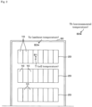
- Fig. 2 is a view illustrating an example of a structure of a battery board 30.
- a plurality of (three in the example of Fig. 2 ) modules 20 are disposed inside the battery board 30.
- a plurality of (8 in the example of Fig. 2 ) cells (also referred to as energy storage devices) 10 are connected in series.
- the cells 10 in the module 20 are not limited to those connected in series, but may be connected in parallel or a combination of series and parallel.
- a temperature of a surface S1 of the cell 10 is represented by a cell temperature T
- a temperature of a required place S2 of a cell ambient layer in the battery board 30 around the cell 10 is represented by an ambient temperature Ta
- a temperature of a required place S3 of an environmental temperature layer outside the battery board 30 is represented by an environmental temperature Tb.
- the place S3 is a place where a temperature sensor is installed.
- the environmental temperature Tb is a temperature outside the battery board 30, for example, a temperature of a room in which the battery board 30 is installed, and can be a set temperature set to a required temperature depending on an operation state of the power storage system.
- the energy storage device is preferably a rechargeable device such as a secondary battery such as a lead-acid battery and a lithium ion battery or a capacitor. Apart of the energy storage device may be a non-rechargeable primary battery.
- the operation data may include data actually obtained not only during the operation of the energy storage system but also at a trial run before the operation of the energy storage system, a final stage of design, or the like.
- the operation data includes time series data such as a set temperature of the power storage system and a load pattern for the power storage system.
- Fig. 3 is a view illustrating an example of the operation data.
- Fig. 3A illustrates an example of environmental temperature data.
- a vertical axis indicates temperature
- a horizontal axis indicates time.
- the environmental temperature data is time-series temperature data managing the temperature at which the power storage system is installed so as to set and maintain the temperature at a required temperature.
- the environmental temperature data can be time-series data of an operation period from an operation start to an operation end of the power storage system, and the operation period can be an appropriate period such as one day, one week, two weeks, one month, three months, half a year, one year, or the like depending on the operation state of the power storage system.
- one day is illustrated in a time unit from 0:00 to 24:00.
- Fig. 3B illustrates an example of the load pattern.
- the vertical axis indicates voltage
- the horizontal axis indicates time.
- the load pattern is also referred to as a power pattern, is power data input to the power storage system, and can be positive power data during charge of the power storage system and be negative power data during discharge of the power storage system.
- the load pattern may be time-series data of the operation period from the operation start to the operation end of the power storage system, and the operation period may be an appropriate period such as one day, one week, two weeks, one month, three months, half a year, one year, or the like depending on the operation state of the power storage system.
- one day is illustrated in a time unit from 0:00 to 24:00.
- the storage 53 is configured of a semiconductor memory, a hard disk, or the like, and can hold the operation data acquired by the input unit 52.
- the storage 53 holds a mathematical model 61 and a temperature estimation model 62.
- each of the mathematical model 61 and the temperature estimation model 62 is an execution code executed by a programming language or numerical analysis software, and specifically, the model execution unit 54 provides an execution environment of each of the mathematical model 61 and the temperature estimation model 62.
- the model execution unit 54 can include a CPU, a ROM, and a RAM, or may include a graphics processing unit (GPU).
- the model execution unit 54 executes processing for inputting input data to the mathematical model 61 and outputting output data from the mathematical model 61.
- the model execution unit 54 executes processing for inputting input data to the temperature estimation model 62 and outputting output data from the temperature estimation model 62.
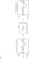
- Fig. 4 is a view illustrating an example of an arithmetic operation by the mathematical model 61.
- the mathematical model 61 when the load pattern (time-series data of power) is input to the mathematical model 61, the mathematical model 61 outputs charge-discharge data (current pattern).
- the charge-discharge data can be time-series data of a charge current or a discharge current of the power storage system (more specifically, each cell).
- the mathematical model 61 is a model in which a characteristic of the cell is mathematically described using an algebraic equation, a differential equation, and a characteristic parameter, and is obtained by executing simulation.
- the mathematical model 61 is not required to be included.
- Fig. 5 is a view illustrating an example of the arithmetic operation by the temperature estimation model 62.
- the temperature estimation model 62 includes an ambient temperature estimation model 621 and a cell temperature estimation model 622.
- the ambient temperature estimation model 621 When the environmental temperature data (represented by Tb) and the charge-discharge data of the power storage system are input to the ambient temperature estimation model 621, the ambient temperature estimation model 621 outputs the ambient temperature Ta.
- the cell temperature estimation model 622 outputs a cell temperature T (the time-series data of the estimated value of the cell temperature).
- the ambient temperature estimation model 621 and the cell temperature estimation model 622 are executed in synchronization with sampling timing of the time-series data. Details of the ambient temperature estimation model 621 and the cell temperature estimation model 622 will be described below.
- the ambient temperature estimation model 621 can update the ambient temperature using the following arithmetic expression (1).
- Ta ′ Ta + a ⁇ Q/C p + b ⁇ Ta ⁇ Tb q
- Q represents a calorific value of the cell 10
- C represents heat capacity of the cell 10
- Tb represents the environmental temperature.
- a is a first coefficient
- p is a first exponent
- a and p are collectively referred to as a heat retention parameter.
- b is a second coefficient
- q is a second exponent
- b and q are collectively referred to as a heat transfer parameter of the cell ambient layer and the environmental temperature layer.
- the heat retention parameter and the heat transfer parameter are collectively referred to simply as a parameter.
- the heat retention in the battery board 30 affects the accuracy of the temperature of the cell 10 while the cell 10 is accommodated in the battery board 30. Accordingly, the temperature in the battery board 30 (the temperature in the heat retention state) is defined as the ambient temperature Ta.
- the ambient temperature Ta depends on heat generation of the cell 10, and a calorific value Q of the cell 10 depends on the charge-discharge data of the cell 10.
- the ambient temperature Ta depends on heat transfer between the inside and the outside of the battery board 30, and the heat transfer depends on the environmental temperature data Tb outside the battery board 30. Accordingly, the ambient temperature Ta can be calculated using the charge-discharge data and the environmental temperature data Tb.
- the first temperature variation amount represents a temperature variation amount in the battery board 30 due to the heat generation of the cell 10 caused by the charge-discharge.
- an internal resistance of the cell 10 is denoted by R
- the heat capacity of the cell 10 is denoted by C
- the current of the cell 10 is denoted by i
- the first temperature variation amount given to the ambient temperature in the battery board 30 can be calculated using an equation converted into the temperature as in (Q/C).
- the calorific value Q of the cell 10 may be simply represented by i 2 ⁇ R, and a term of a linear expression of the current i may be further added.
- the first temperature variation amount may be calculated using an expression (Q/C) p that powers the value (Q/C) obtained by dividing the calorific value Q of the cell 10 by the heat capacity C of the cell 10 by the first exponent p. Furthermore, the first temperature variation amount may be calculated by multiplying the expression (Q/C) p by a first coefficient a.
- the heat retention parameters a, p can be real numbers. However, the heat retention parameters a, p can vary depending on design conditions such as capacity and structure of the power storage system, so that an appropriate value may be selected depending on the power storage system. Thus, the first temperature variation amount can be calculated regardless of the structure of the power storage system or the like.
- the second temperature variation amount represents a temperature variation amount in the battery board 30 due to the heat transfer between the environment outside the battery board 30 and the inside of the battery board 30.
- the environmental temperature outside the battery board 30 is denoted by Tb
- the ambient temperature inside the battery board is denoted by Ta.
- the second temperature variation amount given to the ambient temperature in the battery board 30 can be calculated using an expression as (Ta - Tb).
- the second temperature variation amount may be calculated using an expression (Ta - Tb) q that powers the difference (Ta - Tb) between the ambient temperature Ta of the cell 10 and the environmental temperature Tb of the battery board 30 by a second exponent q. Furthermore, the second temperature variation amount may be calculated by multiplying the expression (Ta - Tb) q by a second coefficient b.
- the heat transfer parameters b, q can be real numbers. However, the heat transfer parameters b, q can vary depending on design conditions such as the capacity and structure of the power storage system, so that an appropriate value may be selected depending on the power storage system. Thus, the second temperature variation amount can be calculated regardless of the structure of the power storage system or the like.
- the ambient temperature Ta of the cell ambient layer of the cell 10 in the battery board 30 can be calculated based on the first temperature variation amount and the second temperature variation amount.
- the ambient temperature can be calculated in consideration of both the influence of the heat retention due to air in the battery board 30, the air being heated by the heat generation of the cell 10, and the influence of the heat transfer between the inside and the outside of the battery board 30.
- the cell temperature estimation model 622 can update the cell temperature using arithmetic expression (2).
- T ′ T + Q/C + h ⁇ T ⁇ Ta
- Q indicates the calorific value of the cell
- C indicates the heat capacity of the cell 10
- Ta is the ambient temperature updated by the ambient temperature estimation model 621.
- h is a heat transfer parameter (also simply referred to as a "parameter") of a cell-cell ambient layer.
- the third temperature variation amount represents a variation amount of the cell temperature of the cell 10 due to the heat generation caused by the charge-discharge.
- the calorific value Q of the cell 10 may be simply represented by i 2 ⁇ R, and a term of the linear expression of the current i may be further added.
- the fourth temperature variation amount represents a temperature variation amount due to the heat transfer between the periphery in the battery board 30 and the cell 10.
- the ambient temperature inside the battery board 30 is defined as Ta
- the temperature of the cell 10 is defined as T.
- the fourth temperature variation amount can be calculated using an expression such as h (T - Ta). The influence of the heat retention due to warming of the air in the battery board 30 can be considered using the ambient temperature Ta.
- the temperature of the cell 10 depends on the calorific value of the cell 10
- the temperature of the cell 10 depends on the charge-discharge data of the cell 10.
- the temperature of the cell 10 depends on the heat transfer with the periphery of the cell 10, and the heat transfer depends on the ambient temperature Ta. Accordingly, the temperature of the cell 10 can be calculated using the ambient temperature Ta and the charge-discharge data.
- the temperature of the cell 10 can be estimated based on the third temperature variation amount and the fourth temperature variation amount.
- the temperature of the cell 10 can be calculated in consideration of not only the temperature variation amount due to the heat generation of the cell 10 but also the influence of the heat retention (that is, the ambient temperature Ta that is the temperature inside the battery board 30) caused by the heated air in the battery board 30, the influence of the heat retention inside the battery board 30 can be mimicked, and the temperature of the cell incorporated in the battery board 30 can be accurately estimated.
- the capacity estimation unit 55 can estimate the full charge capacity of the cell 10 (or the power storage system) based on the temperature of the cell 10 (or the power storage system) estimated by the temperature estimation model 62.
- the full charge capacity is a capacity when the cell 10 is fully charged.
- the output unit 56 can output data of the cell temperature estimated by the temperature estimation model 62 to the external device. In addition, the output unit 56 can output the full charge capacity estimated by the capacity estimation unit 55 to the external device.
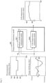
- Fig. 6 is a schematic diagram illustrating a concept of cell temperature estimation by the temperature estimation device.
- the cell ambient layer (Ta) is defined between the cell and the environmental temperature layer (Tb).
- Ta the heat transfer between the cell ambient layer (Ta) and the environmental temperature layer (Tb) is considered while the heat transfer between the cell and the cell ambient layer (Ta) is considered.
- the heat transfer between the cell ambient layer (Ta) and the environmental temperature layer (Tb) can be formulated by the arithmetic expression (1) described above.
- the heat transfer between the cell and the cell ambient layer (Ta) can be formulated by the arithmetic expression (2) described above.
- Fig. 6B schematically illustrates a relationship among the load pattern, the environmental temperature Tb, the cell ambient temperature Ta, and the cell temperature T. That is, the cell ambient temperature Ta can be obtained from a measured value of the load pattern and a measured value of the environmental temperature Tb.
- the load pattern is converted into a charge-discharge pattern, and the converted charge-discharge pattern is used.
- the cell temperature T can be obtained from the load pattern and the cell ambient temperature Ta.
- the load pattern is converted into the charge-discharge pattern, and the converted charge-discharge pattern is used.
- the capacity can be estimated from the cell temperature T.
- Fig. 7 is a view illustrating an example of a temporal change in the full charge capacity of the cell 10.
- the vertical axis indicates the full charge capacity
- the horizontal axis indicates time.
- the manufacturing time point of the cell 10 is denoted by 100%
- the full charge capacity tends to gradually decrease due to aging.
- a decrease degree of the full charge capacity tends to increase as the temperature of the cell 10 increases.
- a curve indicated by a sign A represents the transition of the full charge capacity when the temperature of the cell 10 (referred to as the temperature of the cell alone) is T0.
- each of the cells 10 is accommodated in the battery board 30, and as described above, due to the influence of the heat retention in the battery board 30, the temperature of the cell 10 tends to be higher than that the case of the cell alone.
- the temperature of the cell 10 varies depending on the battery board 30 even when the battery board 30 is operated under the same environment and load condition depending on the design condition and structure of the battery board.
- curves indicated by signs B to D represent transitions of the full charge capacity when the temperatures of the cells 10 in the different battery boards 30 are T1, T2, T3.
- the transition of the full charge capacity is represented by the curve indicated by the sign B.
- a curve of the full charge capacity can be accurately estimated.
- the transition of the full charge capacity as exemplified in Fig. 7 can be obtained by a required simulator.
- the simulator can output the full charge capacity time-series data. That is, when the time-series data of the SOC and the time-series data of the temperature of the power storage system are input, the capacity estimation unit 55 can estimate the full charge capacity of the power storage system by correcting (or providing) the time-series temperature data input to the simulator that outputs the time-series data of the full charge capacity.
- the capacity estimation unit 55 may include the simulator.
- the parameters a, p, b, q in the arithmetic expression (1) of the ambient temperature estimation model 621 can be appropriately set according to the power storage system.
- a parameter setting method will be described below.
- Fig. 8 is a flowchart illustrating an example of a procedure for setting the parameters of the ambient temperature estimation model 621.
- the parameters can be set before the operation of the power storage system is started.
- the set parameters can be updated during the operation of the power storage system to improve the estimation accuracy of the cell temperature.
- the measured value of the temperature of the cell 10 in the battery board 30 is acquired, and the parameter is set using the acquired measured value.
- a subject of the processing is the controller 51 for convenience, but the parameter may be set by a device other than the temperature estimation device 50.
- the controller 51 acquires the measured values of the cell temperature (the temperature of the cell 10 in the battery board 30) when the power storage system is actually operated (worked) and the environmental temperature outside the battery board 30 based on the operation data of the power storage system (S11).
- the work period may be an appropriate period such as one day, one week, or two weeks.
- the measured value of the temperature of the cell 10 or the cell group having the highest temperature among the cells 10 in the battery board 30 may be acquired when the temperature difference of each cell 10 is relatively large according to the position of the cell 10.
- the controller 51 acquires the load pattern and the environmental temperature data that are included in the operation data when the power storage system is actually worked (S12).
- the controller 51 inputs the load pattern to the mathematical model 61 for the power storage system and calculates the charge-discharge data during the work of the power storage system (S13).
- the measured value and the calculated value that are required for setting the parameter can be obtained.
- the controller 51 sets the parameters a, p, b, q of the ambient temperature estimation model 621 to initial values, and sets the parameter h of the cell temperature estimation model 622 to the initial value (S14).
- a predetermined value may be set as the initial value.
- the controller 51 sets the cell temperature T and the ambient temperature Ta to the initial value (environmental temperature Tb) (S15).
- the controller 51 updates the ambient temperature using the charge-discharge data, the environmental temperature data, and the ambient temperature estimation model 621 (S16), and updates the cell temperature using the updated ambient temperature, the charge-discharge data, and the cell temperature estimation model 622 (S17).
- the controller 51 determines whether a difference between the updated cell temperature and the measured value of the cell temperature is within an allowable range (S18). For example, the difference from the measured value of the cell temperature can be calculated using a least squares method.
- the parameter is set (S19), and the pieces of processing after step S15 are continued.
- the parameters are set by changing the parameters a, p, b, q of the ambient temperature estimation model 621. In this way, the parameters a, p, b, q of the ambient temperature estimation model 621 are changed such that the difference between the updated cell temperature and the measured value of the cell temperature falls within the allowable range.
- the controller 51 When the difference between the updated cell temperature and the measured value of the cell temperature is within the allowable range (YES in S18), the controller 51 generates the ambient temperature estimation model 621 and the cell temperature estimation model 622 using the set parameters (S20), and ends the processing.
- a temperature estimation method by the temperature estimation device 50 will be described below. According to the temperature estimation device 50, the cell temperature of the power storage system can be accurately estimated based on the operation data even when the power storage system is not actually worked before the operation of the power storage system is started. A method for estimating the cell temperature will be described below.
- Fig. 9 is a flowchart illustrating an example of a procedure for estimating the cell temperature by the temperature estimation device 50.
- the controller 51 acquires the load pattern and the environmental temperature data that are included in the operation data of the power storage system (S31).
- the controller 51 inputs the load pattern to the mathematical model 61 for the power storage system and calculates the charge-discharge data (S32).
- the processing of step S32 is not required.
- the controller 51 inputs the charge-discharge data and the environmental temperature data to the ambient temperature estimation model 621 to update the ambient temperature (S33), and inputs the charge-discharge data and the updated ambient temperature to the cell temperature estimation model 622 to update the cell temperature (S34).
- the controller 51 determines whether the update of the cell temperature is completed (S35). That is, the controller 51 determines whether all the charge-discharge data and the environmental temperature data are input to the ambient temperature estimation model 621 and the cell temperature estimation model 622.
- the controller 51 When the update of the cell temperature is not completed (NO in S35), the controller 51 continues the pieces of processing after step S33.
- the controller 51 outputs the estimated value of the cell temperature (S36), estimates the full charge capacity based on the estimated cell temperature (S37), and ends the processing.
- the temperature estimation device 50 can also be implemented using a general-purpose computer including a CPU (processor), a GPU, and a RAM (memory). That is, a computer program defining a procedure of each processing as illustrated in Figs. 8 and 9 is loaded into the RAM (memory) included in the computer, and the computer program is executed by the CPU (processor), so that the computer program can be implemented on the computer.
- the computer program may be recorded on a recording medium and distributed.
- the temperature of the cell 10 accommodated in the battery board 30 can be accurately estimated before the operation of the power storage system is started.
- the temperature of the cell 10 can be accurately estimated, so that the full charge capacity of the power storage system can be accurately estimated.
- the full charge capacity of the power storage system can be accurately estimated, so that the life of the power storage system in operation can be estimated from the load assumed in the future, and the time when the life of the power storage system reaches or the time that falls below the minimum required capacity can be accurately estimated.
- preparation for replacement or expansion of the cells 10 (specifically, the module 20) in the power storage system can be systematically and efficiently performed.
- the electric characteristic for example, the internal resistance of the cell 10 or the like depending on the temperature of the power storage system can also be accurately estimated, so that the estimation accuracy of the acceptance performance (charge performance) and the output performance (discharge performance) with respect to the required load power of the power storage system is improved.
- the parameters a, p, b, q of the ambient temperature estimation model 621 can be updated not only before the operation of the power storage system is started but also during the operation.
- the model update unit 57 can update the parameters a, p, b, q of the arithmetic expression (1) of the ambient temperature estimation model 621. Specifically, during the operation, the measured value of the temperature of the cell 10 in the battery board 30 is acquired, and the parameter is updated using the acquired measured value. Because the update procedure is similar to that in the case of Fig. 8 , the description thereof will be omitted. Thus, even when a situation in which the estimation accuracy of the cell temperature by the temperature estimation model 62 decreases due to some cause is assumed in the process for operating the power storage system, the parameter is updated, so that the decrease in the estimation accuracy of the cell temperature can be prevented and the estimation accuracy can be improved.
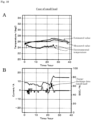
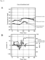
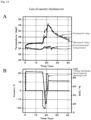
- Fig. 10 is a view illustrating an evaluation example of the estimated value of the cell temperature when the load is small
- Fig. 11 is a view illustrating an evaluation example of the estimated value of the cell temperature when the load is medium
- Fig. 12 is a view illustrating an evaluation example of the estimated value of the cell temperature when the load is large
- Fig. 13 is a view illustrating an evaluation example of the estimated value of the cell temperature in the case of a capacity checking test.
- the vertical axis represents temperature
- the horizontal axis represents time
- charts of the estimated value of the cell temperature, the measured value of the cell temperature, and the environmental temperature are illustrated.
- Figs. 10A , 11A , 12A , and 13A the vertical axis represents temperature
- the horizontal axis represents time
- charts of the estimated value of the cell temperature, the measured value of the cell temperature, and the environmental temperature are illustrated.
- the vertical axis represents current and state of charge (SOC)
- the horizontal axis represents time
- charts of the charge-discharge data and the SOC are illustrated.
- the estimated value of the cell temperature follows in the good state (the state in which the difference between the estimated value and the measured value is within an allowable range) according to the temporal variation of the measured value in all the assumed loads (that is, until the load changes from the small state to the large state).
- the estimated value of the cell temperature follows in the good state according to the temporal variation of the measured value also in the capacity checking test (the test in which the SOC is varied within a predetermined range).
- the estimated value of the cell temperature can reproduce the measured value.
- different parameters are set, so that the same results as those in Figs. 10 , 11 , 12 , and 13 , namely, the estimated value of the cell temperature can be followed in the good state according to the temporal variation of the measured value.
- T T + (Q/C) + k (T - Tb).
- T is the cell temperature before the update
- T' is the cell temperature after the update
- Q indicates the calorific value of the cell
- C indicates the heat capacity of the cell
- Tb indicates the environmental temperature.
- k is a heat transfer parameter of the cell-environmental temperature layer.
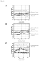
- Fig. 14 is a view illustrating a first example of the evaluation example of the estimated value of the cell temperature in the case of the comparative example.
- Figs. 14A, 14B, and 14C illustrate the case where the load is small, the case where the load is medium, and the case where the load is large, respectively.
- the interval between k is smaller than that in case 1.
- Fig. 14 in case 1, it can be seen that the estimated value of the cell temperature cannot follow the variation of the measured value and the measured value cannot be reproduced in the load state in which the load ranges from small to medium.
- Fig. 15 is a view illustrating a second example of the evaluation example of the estimated value of the cell temperature in the case of the comparative example.
- Figs. 15A, 15B, and 15C illustrate the case where the load is small, the case where the load is medium, and the case where the load is large, respectively.
Landscapes
- Engineering & Computer Science (AREA)
- Manufacturing & Machinery (AREA)
- Chemical & Material Sciences (AREA)
- Chemical Kinetics & Catalysis (AREA)
- Electrochemistry (AREA)
- General Chemical & Material Sciences (AREA)
- Physics & Mathematics (AREA)
- General Physics & Mathematics (AREA)
- Microelectronics & Electronic Packaging (AREA)
- Automation & Control Theory (AREA)
- Secondary Cells (AREA)
- Charge And Discharge Circuits For Batteries Or The Like (AREA)
Applications Claiming Priority (2)
| Application Number | Priority Date | Filing Date | Title |
|---|---|---|---|
| JP2020110549A JP7532948B2 (ja) | 2020-06-26 | 2020-06-26 | 温度推定装置、コンピュータプログラム及び温度推定方法 |
| PCT/JP2021/023213 WO2021261402A1 (ja) | 2020-06-26 | 2021-06-18 | 温度推定装置、コンピュータプログラム及び温度推定方法 |
Publications (2)
| Publication Number | Publication Date |
|---|---|
| EP4175010A1 true EP4175010A1 (de) | 2023-05-03 |
| EP4175010A4 EP4175010A4 (de) | 2025-03-26 |
Family
ID=79281346
Family Applications (1)
| Application Number | Title | Priority Date | Filing Date |
|---|---|---|---|
| EP21829830.5A Pending EP4175010A4 (de) | 2020-06-26 | 2021-06-18 | Temperaturschätzvorrichtung, computerprogramm und temperaturschätzverfahren |
Country Status (4)
| Country | Link |
|---|---|
| US (1) | US20230268571A1 (de) |
| EP (1) | EP4175010A4 (de) |
| JP (1) | JP7532948B2 (de) |
| WO (1) | WO2021261402A1 (de) |
Cited By (1)
| Publication number | Priority date | Publication date | Assignee | Title |
|---|---|---|---|---|
| US20230170724A1 (en) * | 2021-11-29 | 2023-06-01 | Transportation Ip Holdings, Llc | Power control system and method |
Families Citing this family (4)
| Publication number | Priority date | Publication date | Assignee | Title |
|---|---|---|---|---|
| US20220187139A1 (en) * | 2019-03-19 | 2022-06-16 | Gs Yuasa International Ltd. | Estimation device and estimation method |
| CN114649565B (zh) * | 2022-02-19 | 2023-09-29 | 深圳市品众自动化设备有限公司 | 一种锂电池化成分容设备的控制方法及系统 |
| JP2023154437A (ja) * | 2022-04-07 | 2023-10-20 | 株式会社東芝 | 電気車制御装置および分析装置 |
| CN120334772B (zh) * | 2025-06-20 | 2025-09-19 | 宁德时代新能源科技股份有限公司 | 电池温度预测方法、预测装置、电子设备及存储介质 |
Family Cites Families (15)
| Publication number | Priority date | Publication date | Assignee | Title |
|---|---|---|---|---|
| US7745025B2 (en) * | 2006-02-14 | 2010-06-29 | Mti Microfuel Cells Inc. | Fuel cell based rechargable power pack system and associated methods for controlling same |
| JP5533175B2 (ja) * | 2009-05-20 | 2014-06-25 | 日産自動車株式会社 | 組電池監視装置 |
| JP6025197B2 (ja) * | 2010-04-26 | 2016-11-16 | 日本電気株式会社 | 電力制御システム及び方法 |
| TW201224485A (en) * | 2010-12-02 | 2012-06-16 | Ind Tech Res Inst | State-of-charge estimation method and battery control unit |
| JP2014063693A (ja) * | 2012-09-24 | 2014-04-10 | Toshiba Corp | 二次電池装置および電池容量推定システム |
| WO2014118911A1 (ja) | 2013-01-30 | 2014-08-07 | 三菱電機株式会社 | 電池監視装置、蓄電システム、及び制御システム |
| WO2015083208A1 (ja) * | 2013-12-02 | 2015-06-11 | 株式会社日立製作所 | 二次電池モジュール及びこれを備えた二次電池システム |
| EP3128641B1 (de) | 2014-04-01 | 2020-01-29 | Kabushiki Kaisha Toshiba | Speicherzellensystem und verfahren zur anordnung eines zellmoduls |
| JP6162884B2 (ja) | 2014-09-08 | 2017-07-12 | 株式会社東芝 | 電池パック、制御回路および制御方法 |
| US10333184B2 (en) * | 2015-09-09 | 2019-06-25 | General Electric Company | Heat flux assembly for an energy storage device |
| TWI581542B (zh) * | 2016-03-01 | 2017-05-01 | 財團法人工業技術研究院 | 電池管理系統及應用其之電池系統 |
| US10436851B2 (en) | 2016-07-29 | 2019-10-08 | Con Edison Battery Storage, Llc | Electrical energy storage system with battery resistance estimation |
| JP6544489B2 (ja) * | 2016-08-05 | 2019-07-17 | 株式会社Gsユアサ | 蓄電素子状態推定装置及び蓄電素子状態推定方法 |
| US10823786B2 (en) * | 2017-07-28 | 2020-11-03 | Northstar Battery Company, Llc | Battery with internal monitoring system |
| JP6948567B2 (ja) | 2018-01-22 | 2021-10-13 | トヨタ自動車株式会社 | 電池異常検出システム |
-
2020
- 2020-06-26 JP JP2020110549A patent/JP7532948B2/ja active Active
-
2021
- 2021-06-18 EP EP21829830.5A patent/EP4175010A4/de active Pending
- 2021-06-18 WO PCT/JP2021/023213 patent/WO2021261402A1/ja not_active Ceased
- 2021-06-18 US US18/012,941 patent/US20230268571A1/en active Pending
Cited By (1)
| Publication number | Priority date | Publication date | Assignee | Title |
|---|---|---|---|---|
| US20230170724A1 (en) * | 2021-11-29 | 2023-06-01 | Transportation Ip Holdings, Llc | Power control system and method |
Also Published As
| Publication number | Publication date |
|---|---|
| WO2021261402A1 (ja) | 2021-12-30 |
| JP2022007522A (ja) | 2022-01-13 |
| EP4175010A4 (de) | 2025-03-26 |
| JP7532948B2 (ja) | 2024-08-14 |
| US20230268571A1 (en) | 2023-08-24 |
Similar Documents
| Publication | Publication Date | Title |
|---|---|---|
| EP4175010A1 (de) | Temperaturschätzvorrichtung, computerprogramm und temperaturschätzverfahren | |
| US11635467B2 (en) | Evaluation device, computer program, and evaluation method | |
| Lange et al. | Dimensioning battery energy storage systems for peak shaving based on a real-time control algorithm | |
| Wang et al. | Open circuit voltage and state of charge relationship functional optimization for the working state monitoring of the aerial lithium-ion battery pack | |
| Homan et al. | A realistic model for battery state of charge prediction in energy management simulation tools | |
| Miguel et al. | Electrochemical model and sigma point Kalman filter based online oriented battery model | |
| WO2013161540A1 (ja) | 電池システムのメンテナンス管理システム及び方法 | |
| CN118572757B (zh) | 一种基于数字孪生的智能储能系统调控与运维方法及设备 | |
| Zhang et al. | Thermal-enhanced adaptive interval estimation in battery packs with heterogeneous cells | |
| CN112632773B (zh) | 一种风电机组可靠性预测方法 | |
| CN114035052B (zh) | 一种基于能量窗的soc区间标定方法、系统及介质 | |
| Wei et al. | CCEM: Cell-to-Cell Extension Model for low-cost joint estimation of SOC and temperature in supercapacitor series modules | |
| JP6702235B2 (ja) | 蓄電池システム、パワーコンディショナおよび蓄電池の寿命保証方法 | |
| CN116626506A (zh) | 一种变电站蓄电池状态特性预测方法及系统 | |
| CN116482539A (zh) | 基于多维数据驱动的电池荷电状态估计方法、系统、设备及介质 | |
| CN118944249B (zh) | 一种充电剩余时长的计算方法、装置、电池和存储介质 | |
| Rodrigues et al. | Comparison of battery models for energy storage applications on insular grids | |
| Soto et al. | Influence of renewable power fluctuations on the lifetime prediction of lithium-ion batteries in a microgrid environment | |
| KR20250006629A (ko) | 배터리 수명 예측 방법 및 배터리 시스템 | |
| CN116956605A (zh) | 一种用于新能源消纳分析的电力系统规划仿真方法 | |
| Lam et al. | Machine learning for estimation of state-of-charge of energy storage system | |
| JP2023113439A (ja) | 蓄電池を高効率で制御する情報処理方法、プログラム及び情報処理装置 | |
| Mishra et al. | From cell to module: An integrated approach to identification, modeling, simulation, and experimental validation of 21,700 Li-ion batteries for electric vehicles | |
| Camargo-Trigueros et al. | State-of-Health Estimation Based on a Partial Discharge Method for Electric Vehicle Battery Management System into MIL Environment | |
| CN120300955A (zh) | 一种储能电站电化学蓄电池监控设备及监控方法及系统 |
Legal Events
| Date | Code | Title | Description |
|---|---|---|---|
| STAA | Information on the status of an ep patent application or granted ep patent |
Free format text: STATUS: THE INTERNATIONAL PUBLICATION HAS BEEN MADE |
|
| PUAI | Public reference made under article 153(3) epc to a published international application that has entered the european phase |
Free format text: ORIGINAL CODE: 0009012 |
|
| STAA | Information on the status of an ep patent application or granted ep patent |
Free format text: STATUS: REQUEST FOR EXAMINATION WAS MADE |
|
| 17P | Request for examination filed |
Effective date: 20230111 |
|
| AK | Designated contracting states |
Kind code of ref document: A1 Designated state(s): AL AT BE BG CH CY CZ DE DK EE ES FI FR GB GR HR HU IE IS IT LI LT LU LV MC MK MT NL NO PL PT RO RS SE SI SK SM TR |
|
| DAV | Request for validation of the european patent (deleted) | ||
| DAX | Request for extension of the european patent (deleted) | ||
| A4 | Supplementary search report drawn up and despatched |
Effective date: 20250221 |
|
| RIC1 | Information provided on ipc code assigned before grant |
Ipc: H01M 10/48 20060101AFI20250217BHEP |