EP4175031A1 - Batterie secondaire cylindrique et son procédé de fabrication - Google Patents
Batterie secondaire cylindrique et son procédé de fabrication Download PDFInfo
- Publication number
- EP4175031A1 EP4175031A1 EP22204861.3A EP22204861A EP4175031A1 EP 4175031 A1 EP4175031 A1 EP 4175031A1 EP 22204861 A EP22204861 A EP 22204861A EP 4175031 A1 EP4175031 A1 EP 4175031A1
- Authority
- EP
- European Patent Office
- Prior art keywords
- plate
- secondary battery
- electrode
- vent
- cylindrical secondary
- Prior art date
- Legal status (The legal status is an assumption and is not a legal conclusion. Google has not performed a legal analysis and makes no representation as to the accuracy of the status listed.)
- Pending
Links
Images


Classifications
-
- H—ELECTRICITY
- H01—ELECTRIC ELEMENTS
- H01M—PROCESSES OR MEANS, e.g. BATTERIES, FOR THE DIRECT CONVERSION OF CHEMICAL ENERGY INTO ELECTRICAL ENERGY
- H01M50/00—Constructional details or processes of manufacture of the non-active parts of electrochemical cells other than fuel cells, e.g. hybrid cells
- H01M50/30—Arrangements for facilitating escape of gases
- H01M50/394—Gas-pervious parts or elements
-
- H—ELECTRICITY
- H01—ELECTRIC ELEMENTS
- H01M—PROCESSES OR MEANS, e.g. BATTERIES, FOR THE DIRECT CONVERSION OF CHEMICAL ENERGY INTO ELECTRICAL ENERGY
- H01M50/00—Constructional details or processes of manufacture of the non-active parts of electrochemical cells other than fuel cells, e.g. hybrid cells
- H01M50/30—Arrangements for facilitating escape of gases
- H01M50/317—Re-sealable arrangements
-
- H—ELECTRICITY
- H01—ELECTRIC ELEMENTS
- H01M—PROCESSES OR MEANS, e.g. BATTERIES, FOR THE DIRECT CONVERSION OF CHEMICAL ENERGY INTO ELECTRICAL ENERGY
- H01M50/00—Constructional details or processes of manufacture of the non-active parts of electrochemical cells other than fuel cells, e.g. hybrid cells
- H01M50/30—Arrangements for facilitating escape of gases
-
- H—ELECTRICITY
- H01—ELECTRIC ELEMENTS
- H01M—PROCESSES OR MEANS, e.g. BATTERIES, FOR THE DIRECT CONVERSION OF CHEMICAL ENERGY INTO ELECTRICAL ENERGY
- H01M10/00—Secondary cells; Manufacture thereof
- H01M10/04—Construction or manufacture in general
- H01M10/0422—Cells or battery with cylindrical casing
-
- H—ELECTRICITY
- H01—ELECTRIC ELEMENTS
- H01M—PROCESSES OR MEANS, e.g. BATTERIES, FOR THE DIRECT CONVERSION OF CHEMICAL ENERGY INTO ELECTRICAL ENERGY
- H01M10/00—Secondary cells; Manufacture thereof
- H01M10/04—Construction or manufacture in general
- H01M10/0431—Cells with wound or folded electrodes
-
- H—ELECTRICITY
- H01—ELECTRIC ELEMENTS
- H01M—PROCESSES OR MEANS, e.g. BATTERIES, FOR THE DIRECT CONVERSION OF CHEMICAL ENERGY INTO ELECTRICAL ENERGY
- H01M10/00—Secondary cells; Manufacture thereof
- H01M10/04—Construction or manufacture in general
- H01M10/049—Processes for forming or storing electrodes in the battery container
-
- H—ELECTRICITY
- H01—ELECTRIC ELEMENTS
- H01M—PROCESSES OR MEANS, e.g. BATTERIES, FOR THE DIRECT CONVERSION OF CHEMICAL ENERGY INTO ELECTRICAL ENERGY
- H01M10/00—Secondary cells; Manufacture thereof
- H01M10/05—Accumulators with non-aqueous electrolyte
- H01M10/052—Li-accumulators
- H01M10/0525—Rocking-chair batteries, i.e. batteries with lithium insertion or intercalation in both electrodes; Lithium-ion batteries
-
- H—ELECTRICITY
- H01—ELECTRIC ELEMENTS
- H01M—PROCESSES OR MEANS, e.g. BATTERIES, FOR THE DIRECT CONVERSION OF CHEMICAL ENERGY INTO ELECTRICAL ENERGY
- H01M10/00—Secondary cells; Manufacture thereof
- H01M10/05—Accumulators with non-aqueous electrolyte
- H01M10/058—Construction or manufacture
-
- H—ELECTRICITY
- H01—ELECTRIC ELEMENTS
- H01M—PROCESSES OR MEANS, e.g. BATTERIES, FOR THE DIRECT CONVERSION OF CHEMICAL ENERGY INTO ELECTRICAL ENERGY
- H01M10/00—Secondary cells; Manufacture thereof
- H01M10/05—Accumulators with non-aqueous electrolyte
- H01M10/058—Construction or manufacture
- H01M10/0587—Construction or manufacture of accumulators having only wound construction elements, i.e. wound positive electrodes, wound negative electrodes and wound separators
-
- H—ELECTRICITY
- H01—ELECTRIC ELEMENTS
- H01M—PROCESSES OR MEANS, e.g. BATTERIES, FOR THE DIRECT CONVERSION OF CHEMICAL ENERGY INTO ELECTRICAL ENERGY
- H01M50/00—Constructional details or processes of manufacture of the non-active parts of electrochemical cells other than fuel cells, e.g. hybrid cells
- H01M50/10—Primary casings; Jackets or wrappings
- H01M50/102—Primary casings; Jackets or wrappings characterised by their shape or physical structure
- H01M50/107—Primary casings; Jackets or wrappings characterised by their shape or physical structure having curved cross-section, e.g. round or elliptic
-
- H—ELECTRICITY
- H01—ELECTRIC ELEMENTS
- H01M—PROCESSES OR MEANS, e.g. BATTERIES, FOR THE DIRECT CONVERSION OF CHEMICAL ENERGY INTO ELECTRICAL ENERGY
- H01M50/00—Constructional details or processes of manufacture of the non-active parts of electrochemical cells other than fuel cells, e.g. hybrid cells
- H01M50/10—Primary casings; Jackets or wrappings
- H01M50/147—Lids or covers
- H01M50/148—Lids or covers characterised by their shape
- H01M50/152—Lids or covers characterised by their shape for cells having curved cross-section, e.g. round or elliptic
-
- H—ELECTRICITY
- H01—ELECTRIC ELEMENTS
- H01M—PROCESSES OR MEANS, e.g. BATTERIES, FOR THE DIRECT CONVERSION OF CHEMICAL ENERGY INTO ELECTRICAL ENERGY
- H01M50/00—Constructional details or processes of manufacture of the non-active parts of electrochemical cells other than fuel cells, e.g. hybrid cells
- H01M50/10—Primary casings; Jackets or wrappings
- H01M50/147—Lids or covers
- H01M50/155—Lids or covers characterised by the material
- H01M50/157—Inorganic material
- H01M50/159—Metals
-
- H—ELECTRICITY
- H01—ELECTRIC ELEMENTS
- H01M—PROCESSES OR MEANS, e.g. BATTERIES, FOR THE DIRECT CONVERSION OF CHEMICAL ENERGY INTO ELECTRICAL ENERGY
- H01M50/00—Constructional details or processes of manufacture of the non-active parts of electrochemical cells other than fuel cells, e.g. hybrid cells
- H01M50/10—Primary casings; Jackets or wrappings
- H01M50/183—Sealing members
- H01M50/184—Sealing members characterised by their shape or structure
-
- H—ELECTRICITY
- H01—ELECTRIC ELEMENTS
- H01M—PROCESSES OR MEANS, e.g. BATTERIES, FOR THE DIRECT CONVERSION OF CHEMICAL ENERGY INTO ELECTRICAL ENERGY
- H01M50/00—Constructional details or processes of manufacture of the non-active parts of electrochemical cells other than fuel cells, e.g. hybrid cells
- H01M50/10—Primary casings; Jackets or wrappings
- H01M50/183—Sealing members
- H01M50/186—Sealing members characterised by the disposition of the sealing members
-
- H—ELECTRICITY
- H01—ELECTRIC ELEMENTS
- H01M—PROCESSES OR MEANS, e.g. BATTERIES, FOR THE DIRECT CONVERSION OF CHEMICAL ENERGY INTO ELECTRICAL ENERGY
- H01M50/00—Constructional details or processes of manufacture of the non-active parts of electrochemical cells other than fuel cells, e.g. hybrid cells
- H01M50/10—Primary casings; Jackets or wrappings
- H01M50/183—Sealing members
- H01M50/186—Sealing members characterised by the disposition of the sealing members
- H01M50/188—Sealing members characterised by the disposition of the sealing members the sealing members being arranged between the lid and terminal
-
- H—ELECTRICITY
- H01—ELECTRIC ELEMENTS
- H01M—PROCESSES OR MEANS, e.g. BATTERIES, FOR THE DIRECT CONVERSION OF CHEMICAL ENERGY INTO ELECTRICAL ENERGY
- H01M50/00—Constructional details or processes of manufacture of the non-active parts of electrochemical cells other than fuel cells, e.g. hybrid cells
- H01M50/10—Primary casings; Jackets or wrappings
- H01M50/183—Sealing members
- H01M50/19—Sealing members characterised by the material
- H01M50/193—Organic material
-
- H—ELECTRICITY
- H01—ELECTRIC ELEMENTS
- H01M—PROCESSES OR MEANS, e.g. BATTERIES, FOR THE DIRECT CONVERSION OF CHEMICAL ENERGY INTO ELECTRICAL ENERGY
- H01M50/00—Constructional details or processes of manufacture of the non-active parts of electrochemical cells other than fuel cells, e.g. hybrid cells
- H01M50/30—Arrangements for facilitating escape of gases
- H01M50/342—Non-re-sealable arrangements
-
- H—ELECTRICITY
- H01—ELECTRIC ELEMENTS
- H01M—PROCESSES OR MEANS, e.g. BATTERIES, FOR THE DIRECT CONVERSION OF CHEMICAL ENERGY INTO ELECTRICAL ENERGY
- H01M50/00—Constructional details or processes of manufacture of the non-active parts of electrochemical cells other than fuel cells, e.g. hybrid cells
- H01M50/30—Arrangements for facilitating escape of gases
- H01M50/342—Non-re-sealable arrangements
- H01M50/3425—Non-re-sealable arrangements in the form of rupturable membranes or weakened parts, e.g. pierced with the aid of a sharp member
-
- H—ELECTRICITY
- H01—ELECTRIC ELEMENTS
- H01M—PROCESSES OR MEANS, e.g. BATTERIES, FOR THE DIRECT CONVERSION OF CHEMICAL ENERGY INTO ELECTRICAL ENERGY
- H01M50/00—Constructional details or processes of manufacture of the non-active parts of electrochemical cells other than fuel cells, e.g. hybrid cells
- H01M50/30—Arrangements for facilitating escape of gases
- H01M50/35—Gas exhaust passages comprising elongated, tortuous or labyrinth-shaped exhaust passages
- H01M50/367—Internal gas exhaust passages forming part of the battery cover or case; Double cover vent systems
-
- H—ELECTRICITY
- H01—ELECTRIC ELEMENTS
- H01M—PROCESSES OR MEANS, e.g. BATTERIES, FOR THE DIRECT CONVERSION OF CHEMICAL ENERGY INTO ELECTRICAL ENERGY
- H01M50/00—Constructional details or processes of manufacture of the non-active parts of electrochemical cells other than fuel cells, e.g. hybrid cells
- H01M50/50—Current conducting connections for cells or batteries
- H01M50/572—Means for preventing undesired use or discharge
- H01M50/584—Means for preventing undesired use or discharge for preventing incorrect connections inside or outside the batteries
- H01M50/586—Means for preventing undesired use or discharge for preventing incorrect connections inside or outside the batteries inside the batteries, e.g. incorrect connections of electrodes
-
- H—ELECTRICITY
- H01—ELECTRIC ELEMENTS
- H01M—PROCESSES OR MEANS, e.g. BATTERIES, FOR THE DIRECT CONVERSION OF CHEMICAL ENERGY INTO ELECTRICAL ENERGY
- H01M50/00—Constructional details or processes of manufacture of the non-active parts of electrochemical cells other than fuel cells, e.g. hybrid cells
- H01M50/50—Current conducting connections for cells or batteries
- H01M50/572—Means for preventing undesired use or discharge
- H01M50/584—Means for preventing undesired use or discharge for preventing incorrect connections inside or outside the batteries
- H01M50/59—Means for preventing undesired use or discharge for preventing incorrect connections inside or outside the batteries characterised by the protection means
- H01M50/593—Spacers; Insulating plates
-
- Y—GENERAL TAGGING OF NEW TECHNOLOGICAL DEVELOPMENTS; GENERAL TAGGING OF CROSS-SECTIONAL TECHNOLOGIES SPANNING OVER SEVERAL SECTIONS OF THE IPC; TECHNICAL SUBJECTS COVERED BY FORMER USPC CROSS-REFERENCE ART COLLECTIONS [XRACs] AND DIGESTS
- Y02—TECHNOLOGIES OR APPLICATIONS FOR MITIGATION OR ADAPTATION AGAINST CLIMATE CHANGE
- Y02E—REDUCTION OF GREENHOUSE GAS [GHG] EMISSIONS, RELATED TO ENERGY GENERATION, TRANSMISSION OR DISTRIBUTION
- Y02E60/00—Enabling technologies; Technologies with a potential or indirect contribution to GHG emissions mitigation
- Y02E60/10—Energy storage using batteries
-
- Y—GENERAL TAGGING OF NEW TECHNOLOGICAL DEVELOPMENTS; GENERAL TAGGING OF CROSS-SECTIONAL TECHNOLOGIES SPANNING OVER SEVERAL SECTIONS OF THE IPC; TECHNICAL SUBJECTS COVERED BY FORMER USPC CROSS-REFERENCE ART COLLECTIONS [XRACs] AND DIGESTS
- Y02—TECHNOLOGIES OR APPLICATIONS FOR MITIGATION OR ADAPTATION AGAINST CLIMATE CHANGE
- Y02P—CLIMATE CHANGE MITIGATION TECHNOLOGIES IN THE PRODUCTION OR PROCESSING OF GOODS
- Y02P70/00—Climate change mitigation technologies in the production process for final industrial or consumer products
- Y02P70/50—Manufacturing or production processes characterised by the final manufactured product
Definitions
- Embodiments relate to a cylindrical secondary battery in which an internal gas is removable, and a method for manufacturing the same.
- a secondary battery includes a cell provided with an electrode assembly, which includes a positive electrode, a negative electrode, and a separator interposed between the positive electrode and the negative electrode, and an electrolyte impregnated in the electrode assembly.
- the secondary battery may be provided in a variety of outer appearances such as cylindrical, prismatic, pouch type, and the like depending on the use.
- the cylindrical secondary battery has a structure in which an electrode assembly and an electrolyte are accommodated inside a cylindrical can, and one end of the can is sealed with a cap assembly.
- a secondary battery may generate a gas inside the secondary battery due to repetitive charging and discharging and internal chemical factors.
- the cap assembly and the can are deformed due to the generation of the gas.
- An aspect of the present disclosure provides a cylindrical secondary battery, in which an internal gas is removable, and a method for manufacturing the same.
- a cylindrical secondary battery includes: a cylindrical can; an electrode assembly in which a first electrode plate, a second electrode plate, and a separator are wound and which is accommodated in the can; and a cap assembly which is insulated from the can and electrically connected to the electrode assembly and through which a degassing hole passes to communicate with the inside of the can.
- the cap assembly may include: a vent plate coupled to one side of the can and spaced apart from the degassing hole to provide a notch; a cap down plate which is disposed between the vent plate and the electrode assembly so as to be electrically connected to the electrode assembly and through which a plurality of slots pass; and a gasket disposed between the vent plate and the can to insulate the vent plate and the can from each other.
- the vent plate may include: a first support that is in contact with the cap down plate; a vent part which is connected to the outside of the first support so as to be integrated with the first support and in which the notch is provided; and a second support connected to the outside of the vent part so as to be integrated with the vent part and coupled to the can with the gasket therebetween.
- the second support may include: a first region disposed toward the vent part and having a thickness greater than that of the vent part; and a second region having a thickness relatively less than that of the first region.
- the degassing hole may be defined in the first region.
- the cap down plate may have a diameter less than that of the vent plate, and a top surface of an edge of the cap down plate may be in close contact with and welded to a portion of a bottom surface of an edge of the vent plate.
- the cap assembly may further include a resin pin or rubber pin, which is press-fitted into the degassing hole to close the degassing hole after being assembled with the can.
- the cap assembly may further include a sealing member that closes the degassing hole after removing the resin pin or rubber pin when a gas is generated inside the can.
- the sealing member may include a press-fitting ball or resin or is coupled to the degassing hole in a male and female structure.
- a method for manufacturing a cylindrical secondary battery includes: accommodating an electrode assembly in a can so as to be electrically connected to the can; electrically connecting a cap assembly to the electrode assembly; assembling the cap assembly with the can; inserting a resin pin or rubber pin into a hole passing through the cap assembly to close the hole; and coupling a sealing member to the hole passing through the cap assembly to close the hole after discharging a gas by removing the resin pin or rubber pin when the gas is generated.
- first As used herein, terms such as "first,” “second,” etc. are used to describe various members, components, areas, layers, and/or portions. However, it is obvious that the members, components, areas, layers, and/or portions should not be defined by these terms. The terms do not mean a particular order, up and down, or superiority, and are used only for distinguishing one member, component, area, layer, or portion from another member, component, area, layer, or portion. Thus, a first member, component, area, layer, or portion which will be described may also refer to a second member, component, area, layer, or portion, without departing from the teaching of the present invention.
- an upper side is defined as an upper portion
- a lower side is defined as a lower portion based on FIG. 1 ).
- FIG. 1 is a cross-sectional view illustrating a cylindrical secondary battery according an embodiment.
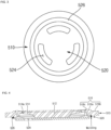
- FIG. 2 is a plan view illustrating a cap assembly of FIG. 1 .
- FIG. 3 is a plan view illustrating a rear surface of the cap assembly of FIG. 1 .
- FIG. 4 is a cross-sectional view illustrating the cap assembly of FIG. 1 .
- a cylindrical secondary battery 10 may include a cylindrical can 100, an electrode assembly 200 inserted into the can 100, first and second electrode collector plates 300 and 400 electrically connected to the electrode assembly 200, and a cap assembly 500 coupled to one end of the can 100.
- the can 100 may include a circular bottom part 110 and a side part 130 extending upward from the bottom part 110.
- the side part 130 has a cylindrical shape, and an upper end of the side part 130 is opened to define an opening.
- the bottom part 110 and the side part 130 may be integrated with each other or may be separately provided to be coupled to each other.
- the electrode assembly 200 and an electrolyte may be accommodated into the can 100 through the opening, and the cap assembly 500 may be coupled to the opening to seal the can 100.
- the can 100 may be made of steel, a steel alloy, nickel-plated steel, a nickel-plated steel alloy, aluminium, an aluminium alloy, or an equivalent thereof, but is not limited thereto.
- a beading part 132 may be concavely recessed inward adjacent to an upper end of the side part 130, and a crimping part 134 in which an end of the side part 130 is bent may be disposed on an upper portion of the beading part 132.
- the beading part 132 supports a lower portion of the cap assembly 500, and the crimping part 134 supports an upper portion of the cap assembly 500.
- the electrode assembly 200 may include a first electrode plate, a second electrode plate, and a separator.
- the first electrode plate may be a positive electrode plate on which a positive electrode active material layer (e.g., transition metal oxide (LiCoO 2 , LiNiO 2 , LiMn 2 O 4 , etc.)) is disposed on each of both surfaces thereof.
- a positive electrode active material layer e.g., transition metal oxide (LiCoO 2 , LiNiO 2 , LiMn 2 O 4 , etc.
- a first electrode non-coating portion to which the positive electrode active material layer is not applied may be disposed on a portion of the first electrode plate.
- the first electrode non-coating portion may be disposed to face the opening of the can 100.
- the second electrode plate may be a negative electrode plate on which a negative electrode active material layer (e.g., graphite, carbon, etc.) is disposed on each of both surfaces thereof.
- a second electrode non-coating portion to which the negative electrode active material layer is not applied may be disposed on a portion of the second electrode plate.
- the second electrode non-coating portion may be disposed to face the bottom part 110 of the can 100.
- the separator may be interposed between the first electrode plate and the second electrode plate to prevent short circuit from occurring and allow lithium ions to move only.
- the first electrode plate may be aluminium (Al) foil
- the second electrode plate may be copper (Cu) or nickel (Ni) foil
- the separator may be made of polyethylene (PE) or polypropylene (PP), but the embodiment is not limited to the above materials.
- the first electrode plate, the second electrode plate, and the separator may be wound in a substantially cylindrical shape and accommodated in the can 100.
- the first electrode non-coating portion may be electrically connected to the first electrode collector plate
- the second electrode non-coating portion may be electrically connected to the second electrode collector plate 400.
- the first electrode collector plate 300 may be welded to the first electrode non-coating portion of the positive electrode plate and may be electrically connected to the cap assembly 500 by a first electrode lead 310. Thus, the first electrode plate and the cap assembly 500 may be electrically connected to each other.
- the first electrode collector plate 300 may have an approximately circular plate shape.
- a base material tab may be disposed on the first electrode plate, and the first electrode collector plate 300 may be directly welded to the base material tab of the first electrode plate.
- the second electrode collector plate 400 may be welded to the second electrode non-coating portion of the negative electrode plate and may be welded to the bottom part 110 of the can 100. Accordingly, the second electrode plate and the can 100 may be electrically connected to each other.
- the second electrode collector plate 400 may have an approximately circular plate shape.
- a substrate tab may be disposed on the second electrode plate, and the second electrode collector plate 400 may be welded to the bottom part 110 of the can 100.
- the cap assembly 500 may include a vent plate 510, a cap down plate 520, and a gasket 530.
- the vent plate 510 may have an approximately circular plate and include a first support 512 that is in contact with the cap down plate 520, a vent part 514 which is connected to the first support 512 and in which a notch 514a is provided, and a second support 516 connected to the vent part 514 and coupled to the side part 130 of the can 100.
- the first support 512 may be a portion having a predetermined thickness, and a bottom surface of the first support 512 may be in contact with a top surface of the cap down plate 520.
- the first support 512 may have a thickness that is gradually reduced toward the outside.
- the vent part 514 may be integrally provided outside the first support 512.
- the vent part 514 is disposed between the first support 512 and the second support 516 and has a relatively thin thickness compared to each of the first support 512 and the second support 516.
- the notch 514a is provided in a circular shape on the vent part 514, and when the gas is generated, if a gas pressure exceeds a predetermined level, the notch 514a is broken to serve as a gas discharge passage.
- the notch 514a may be provided at a side closer to the second support 516.
- the second support 516 may be an edge portion of the vent plate 510, be connected to the outside of the vent part 514, and be integrated with the vent part 514.
- the second support 516 may include a first region 516a having a thickness similar to or greater than that of the first support 512 and a second region 516b having a thickness that relatively less than that of the first region 516a.
- a degassing hole 516c is defined to pass through the first region 516a. To secure rigidity for defining the degassing hole 516c, the thickness of the first region 516a may be greater than that of the second region 516b or the first support 512.
- a height of a top surface of the first region 516a may be greater than that of an edge of the vent part 514.
- a height of the top surface of the second region 516b may be less than that of the top surface of the first region 516a.
- the gasket 530 is coupled to the outside of the second region 516b, and the vent plate 510 is fixed by the crimping part 134 of the can 100 with the gasket 530 therebetween. Also, a portion of the cap down plate 520 is in close contact with a bottom surface of the first region 516a.
- the degassing hole 516c is a hole penetrated from the top surface to the bottom surface of the first region 516a.
- the degassing hole 516c may be defined to be adjacent to the notch 514a in the first region 516a.
- the degassing hole 516c may have a shape of which a diameter gradually decreases from an upper portion to a lower portion.
- a portion of the lower portion of the degassing hole 516c may have a shape of which the reduced diameter is maintained.
- the degassing hole 516c communicates with the inside of the can 100 through the cap down plate 520.
- the gas When a gas is generated inside the secondary battery 10, the gas may be discharged between the vent plate 510 and the cap down plate 520 through a slot 524 defined in the cap down plate 520 and then be discharged to the outside through the degassing hole 516c.
- a bottom surface of the first support 512 may protrude downward from a bottom surface of the second support 516.
- the cap down plate 520 is disposed below the vent plate 510 and is electrically connected to the vent plate 510 and the first electrode collector plate 300.
- the cap down plate 520 is illustrated in FIG. 1 as being electrically connected to the first electrode collector plate 300 by the first electrode lead 310, the cap down plate 520 may be directly connected to the first electrode collector plate 300 through welding.
- the cap down plate 520 may have an approximately circular shape and may have a diameter less than that of the vent plate 510.
- a top surface of an edge of the cap down plate 520 is in close contact with the bottom surface of the second support 516 of the vent plate 510. This portion is defined as a third support 526.
- a top surface of each of other portions with respect to the third support 526 may have a height less than that of a top surface than the third support 526. That is, the top surface of the cap down plate 520 excluding the third support 526 may be concave toward the first electrode collector plate 300.
- a plurality of slots 524 serving as passages when a gas is generated may be defined to pass through a plate surface of the cap down plate 520. The slots 524 may be defined between a central portion of the cap down plate 520 and the third support 526.
- the top surface of the cap down plate 520 is in close contact with the bottom surface of the first support 512, and the top surface of the third support 526 is in close contact with the bottom surface of the second support 516.
- the portion at which the second support and the third support 526 are in close contact with each other may be welded to provide a welded part. Since the second support 516 and the third support 526 are welded to each other, even though the notch 514a is ruptured when the gas is generated inside the secondary battery 10 to remove a portion of the first support 512, the coupling between the vent plate 510 and the cap down plate 520 may be maintained, and thus, the electrical connection between the electrode assembly 200 and the cap assembly 500 may be maintained.
- the gasket 530 has an approximately ring shape and may have a predetermined width.
- the gasket 530 may be provided to surround a portion or the whole of the second region 516b of the second support 516.
- the cap assembly 500 is insulated from the can 100 by the gasket 530 and is electrically connected to the first electrode collector plate 300. Therefore, when the first electrode collector plate 300 is a positive electrode collector plate, the cap assembly 500 may serve as a positive electrode.
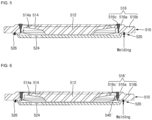
- FIG. 5 is a cross-sectional view illustrating a sealing member of the cap assembly of FIG. 4 .
- the electrode assembly 200 may be inserted into a can 100 so that the first electrode collector plate 300 faces upward, and then, an electrolyte is injected.
- an electrolyte is injected.
- the cap assembly 500 is seated on a beading part 132 of a side part 130. Thereafter, a crimping part 134 is formed to assemble the cap assembly 500 to the can 100.
- a resin pin e.g., PP, PE, etc.
- a rubber pin is temporarily press-fitted into a degassing hole 516c to seal the secondary battery 10. That is, during the assembly process of the secondary battery 10, the degassing hole 516c is temporarily sealed by the resin pin or the rubber pin.
- the resin When a gas is generated inside the secondary battery 10 by charging and discharging before the secondary battery is released, the resin may be removed to discharge the internal gas through the degassing hole 516c.
- the sealing member When the gas is completely discharged, as illustrated in FIG. 5 , the sealing member may be press-fitted into the degassing hole 516c to close the degassing hole 516c.
- the sealing member 540 may include a press-fitting ball or resin.
- the sealing member 540 may have a size greater than that of the degassing hole 516c.
- FIG. 6 is a cross-sectional view illustrating a sealing member according to another embodiment.
- a sealing member 540' may be coupled to a degassing hole 516c' in the form of insertion rather than press fitting. That is, the sealing member 540' is manufactured to have a shape and size corresponding to those of the degassing hole 516c', thereby sealing the degassing hole 516c'.
- the sealing member 540' and the degassing hole 516c' may be provided in a male and female structure so that the sealing member 540' is separated from the degassing hole 516c', or a gas does not leak.
- Various structures may be applied to the male and female structure, such as a screw thread and screw groove structure, a concave-convex structure, and a tapered hook and hook groove structure.
- the degassing function since the degassing function is applied to remove the gas generated before the product shipment, the deformation of the can and the cap assembly may be reduced. In addition, the swelling of the electrode assembly due to the generation of the internal gas may be prevented from occurring to reduce the performance deterioration of the secondary battery.
Landscapes
- Chemical & Material Sciences (AREA)
- Chemical Kinetics & Catalysis (AREA)
- Electrochemistry (AREA)
- General Chemical & Material Sciences (AREA)
- Engineering & Computer Science (AREA)
- Manufacturing & Machinery (AREA)
- Inorganic Chemistry (AREA)
- Materials Engineering (AREA)
- Sealing Battery Cases Or Jackets (AREA)
- Secondary Cells (AREA)
- Gas Exhaust Devices For Batteries (AREA)
Applications Claiming Priority (1)
| Application Number | Priority Date | Filing Date | Title |
|---|---|---|---|
| KR1020210148843A KR102693189B1 (ko) | 2021-11-02 | 2021-11-02 | 원통형 이차전지 및 이차전지의 제조방법 |
Publications (1)
| Publication Number | Publication Date |
|---|---|
| EP4175031A1 true EP4175031A1 (fr) | 2023-05-03 |
Family
ID=84047740
Family Applications (1)
| Application Number | Title | Priority Date | Filing Date |
|---|---|---|---|
| EP22204861.3A Pending EP4175031A1 (fr) | 2021-11-02 | 2022-11-01 | Batterie secondaire cylindrique et son procédé de fabrication |
Country Status (4)
| Country | Link |
|---|---|
| US (1) | US20230133138A1 (fr) |
| EP (1) | EP4175031A1 (fr) |
| KR (1) | KR102693189B1 (fr) |
| CN (1) | CN116073063B (fr) |
Families Citing this family (1)
| Publication number | Priority date | Publication date | Assignee | Title |
|---|---|---|---|---|
| KR102946352B1 (ko) * | 2024-12-12 | 2026-03-30 | 주식회사 엘지에너지솔루션 | 캡 플레이트, 배터리 셀 및 이를 포함하는 배터리 팩 및 자동차 |
Citations (5)
| Publication number | Priority date | Publication date | Assignee | Title |
|---|---|---|---|---|
| JPH06187957A (ja) * | 1992-12-18 | 1994-07-08 | Toshiba Battery Co Ltd | 非水電解液電池 |
| US20140377599A1 (en) * | 2011-09-29 | 2014-12-25 | Panasonic Corporation | Sealed secondary battery |
| CN207938663U (zh) * | 2018-01-31 | 2018-10-02 | 比亚迪股份有限公司 | 盖板组件、电池、电池组和车辆 |
| EP3518308A1 (fr) * | 2016-09-20 | 2019-07-31 | Samsung SDI Co., Ltd. | Batterie secondaire |
| US20210119299A1 (en) * | 2017-07-31 | 2021-04-22 | Panasonic Intellectual Property Management Co., Ltd. | Cylindrical battery |
Family Cites Families (18)
| Publication number | Priority date | Publication date | Assignee | Title |
|---|---|---|---|---|
| US4788112A (en) * | 1987-08-17 | 1988-11-29 | Kung Chin Chung | Rechargeable storage battery |
| JPH07263028A (ja) * | 1994-03-25 | 1995-10-13 | Fuji Photo Film Co Ltd | 非水二次電池 |
| JPH09161739A (ja) * | 1995-12-06 | 1997-06-20 | Matsushita Electric Ind Co Ltd | 角形密閉電池 |
| US6265101B1 (en) * | 1998-08-21 | 2001-07-24 | Eveready Battery Company, Inc. | Battery constructions having increased internal volume for active components |
| JP2001338674A (ja) * | 2000-05-26 | 2001-12-07 | Fdk Corp | 二次電池の製造方法および電池用封止栓 |
| JP2004071265A (ja) * | 2002-08-05 | 2004-03-04 | Sanyo Electric Co Ltd | 電池 |
| KR100846986B1 (ko) * | 2005-12-20 | 2008-07-17 | 삼성에스디아이 주식회사 | 리튬 이차전지 및 그 제조방법과 리튬 이차전지용가스방출기구 |
| KR100880321B1 (ko) * | 2006-12-14 | 2009-01-28 | 삼성에스디아이 주식회사 | 이차전지 |
| KR101396703B1 (ko) * | 2008-03-05 | 2014-05-19 | 삼성에스디아이 주식회사 | 가스제거장치 및 이를 이용한 원통형 이차전지 |
| KR100917742B1 (ko) * | 2008-03-13 | 2009-09-15 | 삼성에스디아이 주식회사 | 원통형 이차전지 |
| KR20090124110A (ko) * | 2008-05-29 | 2009-12-03 | 에너그린(주) | 니켈-수소전지용 벤트 플러그 |
| JP5097167B2 (ja) * | 2009-06-05 | 2012-12-12 | パナソニック株式会社 | 組電池 |
| KR20130034285A (ko) * | 2011-09-28 | 2013-04-05 | (주)아이비티 | 전류차단소자 및 이를 구비한 이차 전지 |
| JP5994670B2 (ja) * | 2013-02-15 | 2016-09-21 | 株式会社豊田自動織機 | 蓄電装置及び蓄電装置の製造方法 |
| KR102706444B1 (ko) * | 2020-02-06 | 2024-09-13 | 주식회사 엘지에너지솔루션 | 이차전지 제조방법 및 그를 포함하는 전지팩 제조방법 |
| KR102906872B1 (ko) * | 2020-03-17 | 2026-01-02 | 삼성에스디아이 주식회사 | 이차전지 |
| CN214505580U (zh) * | 2021-02-26 | 2021-10-26 | 湖北亿纬动力有限公司 | 一种圆柱形锂离子电池 |
| KR102754515B1 (ko) * | 2021-04-08 | 2025-01-13 | 주식회사 엘지에너지솔루션 | 이차전지 및 이의 제조 방법 |
-
2021
- 2021-11-02 KR KR1020210148843A patent/KR102693189B1/ko active Active
-
2022
- 2022-10-27 US US17/975,382 patent/US20230133138A1/en active Pending
- 2022-11-01 EP EP22204861.3A patent/EP4175031A1/fr active Pending
- 2022-11-02 CN CN202211361039.7A patent/CN116073063B/zh active Active
Patent Citations (5)
| Publication number | Priority date | Publication date | Assignee | Title |
|---|---|---|---|---|
| JPH06187957A (ja) * | 1992-12-18 | 1994-07-08 | Toshiba Battery Co Ltd | 非水電解液電池 |
| US20140377599A1 (en) * | 2011-09-29 | 2014-12-25 | Panasonic Corporation | Sealed secondary battery |
| EP3518308A1 (fr) * | 2016-09-20 | 2019-07-31 | Samsung SDI Co., Ltd. | Batterie secondaire |
| US20210119299A1 (en) * | 2017-07-31 | 2021-04-22 | Panasonic Intellectual Property Management Co., Ltd. | Cylindrical battery |
| CN207938663U (zh) * | 2018-01-31 | 2018-10-02 | 比亚迪股份有限公司 | 盖板组件、电池、电池组和车辆 |
Also Published As
| Publication number | Publication date |
|---|---|
| KR20230063611A (ko) | 2023-05-09 |
| CN116073063B (zh) | 2026-05-12 |
| KR102693189B1 (ko) | 2024-08-09 |
| CN116073063A (zh) | 2023-05-05 |
| US20230133138A1 (en) | 2023-05-04 |
Similar Documents
| Publication | Publication Date | Title |
|---|---|---|
| EP4468506A1 (fr) | Batterie secondaire | |
| US20230231242A1 (en) | Secondary battery | |
| US12199295B2 (en) | Secondary battery | |
| KR102601042B1 (ko) | 원통형 이차전지 | |
| CN101764246B (zh) | 可充电电池 | |
| KR20210145489A (ko) | 이차전지 | |
| US20260066491A1 (en) | Secondary battery | |
| KR20190098495A (ko) | 전극 조립체 및 이를 포함하는 이차전지 | |
| EP4478497A1 (fr) | Batterie secondaire cylindrique | |
| US7666548B2 (en) | Can type secondary battery | |
| KR102761907B1 (ko) | 이차 전지 | |
| KR101416520B1 (ko) | 벤트 구조를 갖는 2차 전지용 캡 플레이트 및 그의 제조방법 | |
| CN111566846A (zh) | 二次电池 | |
| US20230223643A1 (en) | Secondary battery | |
| US20230223622A1 (en) | Secondary battery | |
| US20230133138A1 (en) | Cylindrical secondary battery and method for manufacturing the same | |
| US12244040B2 (en) | Secondary battery | |
| KR102824566B1 (ko) | 원통형 이차전지 | |
| EP4429007A1 (fr) | Batterie rechargeable cylindrique et procédé de fabrication de batterie rechargeable | |
| EP4113711B1 (fr) | Batterie secondaire et son procédé de fabrication | |
| KR20200052738A (ko) | 이차 전지 | |
| US20230361392A1 (en) | Cylindrical secondary battery | |
| KR102963061B1 (ko) | 이차전지용 전극 조립체 및 이를 포함하는 원통형 이차 전지 | |
| US20260100405A1 (en) | Battery cell, battery cell manufacturing device and battery cell manufacturing method | |
| US20250286180A1 (en) | Secondary battery |
Legal Events
| Date | Code | Title | Description |
|---|---|---|---|
| PUAI | Public reference made under article 153(3) epc to a published international application that has entered the european phase |
Free format text: ORIGINAL CODE: 0009012 |
|
| STAA | Information on the status of an ep patent application or granted ep patent |
Free format text: STATUS: REQUEST FOR EXAMINATION WAS MADE |
|
| 17P | Request for examination filed |
Effective date: 20221101 |
|
| AK | Designated contracting states |
Kind code of ref document: A1 Designated state(s): AL AT BE BG CH CY CZ DE DK EE ES FI FR GB GR HR HU IE IS IT LI LT LU LV MC ME MK MT NL NO PL PT RO RS SE SI SK SM TR |
|
| P01 | Opt-out of the competence of the unified patent court (upc) registered |
Effective date: 20230712 |