EP4175164A1 - Aufwärtswandlerzustandssteuerung - Google Patents
Aufwärtswandlerzustandssteuerung Download PDFInfo
- Publication number
- EP4175164A1 EP4175164A1 EP22200848.4A EP22200848A EP4175164A1 EP 4175164 A1 EP4175164 A1 EP 4175164A1 EP 22200848 A EP22200848 A EP 22200848A EP 4175164 A1 EP4175164 A1 EP 4175164A1
- Authority
- EP
- European Patent Office
- Prior art keywords
- voltage level
- power supply
- boost converter
- phase inverter
- converter circuit
- Prior art date
- Legal status (The legal status is an assumption and is not a legal conclusion. Google has not performed a legal analysis and makes no representation as to the accuracy of the status listed.)
- Pending
Links
Images

Classifications
-
- H—ELECTRICITY
- H02—GENERATION; CONVERSION OR DISTRIBUTION OF ELECTRIC POWER
- H02P—CONTROL OR REGULATION OF ELECTRIC MOTORS, ELECTRIC GENERATORS OR DYNAMO-ELECTRIC CONVERTERS; CONTROLLING TRANSFORMERS, REACTORS OR CHOKE COILS
- H02P27/00—Arrangements or methods for the control of AC motors characterised by the kind of supply voltage
- H02P27/04—Arrangements or methods for the control of AC motors characterised by the kind of supply voltage using variable-frequency supply voltage, e.g. inverter or converter supply voltage
- H02P27/06—Arrangements or methods for the control of AC motors characterised by the kind of supply voltage using variable-frequency supply voltage, e.g. inverter or converter supply voltage using DC to AC converters or inverters
- H02P27/08—Arrangements or methods for the control of AC motors characterised by the kind of supply voltage using variable-frequency supply voltage, e.g. inverter or converter supply voltage using DC to AC converters or inverters with pulse width modulation
-
- H—ELECTRICITY
- H02—GENERATION; CONVERSION OR DISTRIBUTION OF ELECTRIC POWER
- H02M—APPARATUS FOR CONVERSION BETWEEN AC AND AC, BETWEEN AC AND DC, OR BETWEEN DC AND DC, AND FOR USE WITH MAINS OR SIMILAR POWER SUPPLY SYSTEMS; CONVERSION OF DC OR AC INPUT POWER INTO SURGE OUTPUT POWER; CONTROL OR REGULATION THEREOF
- H02M7/00—Conversion of AC power input into DC power output; Conversion of DC power input into AC power output
- H02M7/42—Conversion of DC power input into AC power output without possibility of reversal
- H02M7/44—Conversion of DC power input into AC power output without possibility of reversal by static converters
- H02M7/48—Conversion of DC power input into AC power output without possibility of reversal by static converters using discharge tubes with control electrode or semiconductor devices with control electrode
- H02M7/53—Conversion of DC power input into AC power output without possibility of reversal by static converters using discharge tubes with control electrode or semiconductor devices with control electrode using devices of a triode or transistor type requiring continuous application of a control signal
- H02M7/537—Conversion of DC power input into AC power output without possibility of reversal by static converters using discharge tubes with control electrode or semiconductor devices with control electrode using devices of a triode or transistor type requiring continuous application of a control signal using semiconductor devices only, e.g. single switched pulse inverters
- H02M7/539—Conversion of DC power input into AC power output without possibility of reversal by static converters using discharge tubes with control electrode or semiconductor devices with control electrode using devices of a triode or transistor type requiring continuous application of a control signal using semiconductor devices only, e.g. single switched pulse inverters with automatic control of output wave form or frequency
- H02M7/5395—Conversion of DC power input into AC power output without possibility of reversal by static converters using discharge tubes with control electrode or semiconductor devices with control electrode using devices of a triode or transistor type requiring continuous application of a control signal using semiconductor devices only, e.g. single switched pulse inverters with automatic control of output wave form or frequency by pulse-width modulation
-
- H—ELECTRICITY
- H02—GENERATION; CONVERSION OR DISTRIBUTION OF ELECTRIC POWER
- H02M—APPARATUS FOR CONVERSION BETWEEN AC AND AC, BETWEEN AC AND DC, OR BETWEEN DC AND DC, AND FOR USE WITH MAINS OR SIMILAR POWER SUPPLY SYSTEMS; CONVERSION OF DC OR AC INPUT POWER INTO SURGE OUTPUT POWER; CONTROL OR REGULATION THEREOF
- H02M1/00—Details of apparatus for conversion
- H02M1/0003—Details of control, feedback or regulation circuits
- H02M1/0032—Control circuits allowing low power mode operation, e.g. in standby mode
-
- H—ELECTRICITY
- H02—GENERATION; CONVERSION OR DISTRIBUTION OF ELECTRIC POWER
- H02M—APPARATUS FOR CONVERSION BETWEEN AC AND AC, BETWEEN AC AND DC, OR BETWEEN DC AND DC, AND FOR USE WITH MAINS OR SIMILAR POWER SUPPLY SYSTEMS; CONVERSION OF DC OR AC INPUT POWER INTO SURGE OUTPUT POWER; CONTROL OR REGULATION THEREOF
- H02M1/00—Details of apparatus for conversion
- H02M1/0067—Converter structures employing plural converter units, other than for parallel operation of the units on a single load
- H02M1/007—Plural converter units in cascade
-
- H—ELECTRICITY
- H02—GENERATION; CONVERSION OR DISTRIBUTION OF ELECTRIC POWER
- H02M—APPARATUS FOR CONVERSION BETWEEN AC AND AC, BETWEEN AC AND DC, OR BETWEEN DC AND DC, AND FOR USE WITH MAINS OR SIMILAR POWER SUPPLY SYSTEMS; CONVERSION OF DC OR AC INPUT POWER INTO SURGE OUTPUT POWER; CONTROL OR REGULATION THEREOF
- H02M3/00—Conversion of DC power input into DC power output
- H02M3/02—Conversion of DC power input into DC power output without intermediate conversion into AC
- H02M3/04—Conversion of DC power input into DC power output without intermediate conversion into AC by static converters
- H02M3/10—Conversion of DC power input into DC power output without intermediate conversion into AC by static converters using discharge tubes with control electrode or semiconductor devices with control electrode
- H02M3/145—Conversion of DC power input into DC power output without intermediate conversion into AC by static converters using discharge tubes with control electrode or semiconductor devices with control electrode using devices of a triode or transistor type requiring continuous application of a control signal
- H02M3/155—Conversion of DC power input into DC power output without intermediate conversion into AC by static converters using discharge tubes with control electrode or semiconductor devices with control electrode using devices of a triode or transistor type requiring continuous application of a control signal using semiconductor devices only
- H02M3/156—Conversion of DC power input into DC power output without intermediate conversion into AC by static converters using discharge tubes with control electrode or semiconductor devices with control electrode using devices of a triode or transistor type requiring continuous application of a control signal using semiconductor devices only with automatic control of output voltage or current, e.g. switching regulators
-
- H—ELECTRICITY
- H02—GENERATION; CONVERSION OR DISTRIBUTION OF ELECTRIC POWER
- H02M—APPARATUS FOR CONVERSION BETWEEN AC AND AC, BETWEEN AC AND DC, OR BETWEEN DC AND DC, AND FOR USE WITH MAINS OR SIMILAR POWER SUPPLY SYSTEMS; CONVERSION OF DC OR AC INPUT POWER INTO SURGE OUTPUT POWER; CONTROL OR REGULATION THEREOF
- H02M7/00—Conversion of AC power input into DC power output; Conversion of DC power input into AC power output
- H02M7/42—Conversion of DC power input into AC power output without possibility of reversal
- H02M7/44—Conversion of DC power input into AC power output without possibility of reversal by static converters
- H02M7/48—Conversion of DC power input into AC power output without possibility of reversal by static converters using discharge tubes with control electrode or semiconductor devices with control electrode
- H02M7/53—Conversion of DC power input into AC power output without possibility of reversal by static converters using discharge tubes with control electrode or semiconductor devices with control electrode using devices of a triode or transistor type requiring continuous application of a control signal
- H02M7/537—Conversion of DC power input into AC power output without possibility of reversal by static converters using discharge tubes with control electrode or semiconductor devices with control electrode using devices of a triode or transistor type requiring continuous application of a control signal using semiconductor devices only, e.g. single switched pulse inverters
- H02M7/5387—Conversion of DC power input into AC power output without possibility of reversal by static converters using discharge tubes with control electrode or semiconductor devices with control electrode using devices of a triode or transistor type requiring continuous application of a control signal using semiconductor devices only, e.g. single switched pulse inverters in a bridge configuration
- H02M7/53871—Conversion of DC power input into AC power output without possibility of reversal by static converters using discharge tubes with control electrode or semiconductor devices with control electrode using devices of a triode or transistor type requiring continuous application of a control signal using semiconductor devices only, e.g. single switched pulse inverters in a bridge configuration with automatic control of output voltage or current
-
- H—ELECTRICITY
- H02—GENERATION; CONVERSION OR DISTRIBUTION OF ELECTRIC POWER
- H02P—CONTROL OR REGULATION OF ELECTRIC MOTORS, ELECTRIC GENERATORS OR DYNAMO-ELECTRIC CONVERTERS; CONTROLLING TRANSFORMERS, REACTORS OR CHOKE COILS
- H02P23/00—Arrangements or methods for the control of AC motors characterised by a control method other than vector control
- H02P23/02—Arrangements or methods for the control of AC motors characterised by a control method other than vector control specially adapted for optimising the efficiency at low load
-
- H—ELECTRICITY
- H02—GENERATION; CONVERSION OR DISTRIBUTION OF ELECTRIC POWER
- H02P—CONTROL OR REGULATION OF ELECTRIC MOTORS, ELECTRIC GENERATORS OR DYNAMO-ELECTRIC CONVERTERS; CONTROLLING TRANSFORMERS, REACTORS OR CHOKE COILS
- H02P29/00—Arrangements for regulating or controlling electric motors, appropriate for both AC and DC motors
- H02P29/02—Providing protection against overload without automatic interruption of supply
- H02P29/024—Detecting a fault condition, e.g. short circuit, locked rotor, open circuit or loss of load
- H02P29/028—Detecting a fault condition, e.g. short circuit, locked rotor, open circuit or loss of load the motor continuing operation despite the fault condition, e.g. eliminating, compensating for or remedying the fault
-
- H—ELECTRICITY
- H02—GENERATION; CONVERSION OR DISTRIBUTION OF ELECTRIC POWER
- H02P—CONTROL OR REGULATION OF ELECTRIC MOTORS, ELECTRIC GENERATORS OR DYNAMO-ELECTRIC CONVERTERS; CONTROLLING TRANSFORMERS, REACTORS OR CHOKE COILS
- H02P2201/00—Indexing scheme relating to controlling arrangements characterised by the converter used
-
- H—ELECTRICITY
- H02—GENERATION; CONVERSION OR DISTRIBUTION OF ELECTRIC POWER
- H02P—CONTROL OR REGULATION OF ELECTRIC MOTORS, ELECTRIC GENERATORS OR DYNAMO-ELECTRIC CONVERTERS; CONTROLLING TRANSFORMERS, REACTORS OR CHOKE COILS
- H02P29/00—Arrangements for regulating or controlling electric motors, appropriate for both AC and DC motors
- H02P29/02—Providing protection against overload without automatic interruption of supply
- H02P29/024—Detecting a fault condition, e.g. short circuit, locked rotor, open circuit or loss of load
- H02P29/027—Detecting a fault condition, e.g. short circuit, locked rotor, open circuit or loss of load the fault being an over-current
Definitions
- the present invention relates to converters, and more specifically, to a system and a method for boost converter state control.
- Converters can be used to condition the power for various applications that may have different power requirements from the source. Therefore, there may be a need to increase the voltage supplied from a source using a boost converter or decrease the voltage using a buck converter.
- various types of converters can be used to modify direct current (DC) to alternating current (AC) and vice-versa, which depends on the various applications using the power.
- Electric transport refrigeration units often rely on converters to drive the load such as the compressors that are used to cool the cargo. There may be a need to provide a converter that efficiently interfaces with the compressor.
- a system for controlling a boost converter circuit includes a power supply operable to supply power to a load; a boost converter circuit coupled to the power supply, wherein the boost converter circuit is operable to provide power to the load; a 3-phase inverter coupled to the boost converter, wherein the 3-phase-inverter is operable to provide a 3-phase output; and a controller coupled to the boost converter and the 3-phase inverter.
- the controller is configured to receive a voltage level of a power supply and a voltage level of a 3-phase inverter; compare a power threshold to at least one of: the voltage level of the power supply and the voltage level of the 3-phase inverter; and control an operation of the boost converter circuit to operate in a boost mode or a rectification mode based at least in part on the comparison.
- the controller may be configured to operate the boost converter circuit in the boost mode when the voltage level of the power supply or the voltage level of the 3-phase inverter is greater than the power threshold.
- the controller may be configured to operate the boost converter circuit in the rectification mode when the voltage level of the power supply or the voltage level of the 3-phase inverter is less than the power threshold.
- the controller may be configured to compare the voltage level of the power supply to the voltage of the 3-phase inverter or a voltage level of the load.
- the controller may be configured to operate the boost converter circuit in the boost mode when the voltage level of the power supply is less than the voltage level of the 3-phase inverter or the voltage level of the load.
- the controller may be configured to operate the boost converter circuit in the rectification mode when the voltage level of the power supply is greater than the voltage level of the 3-phase inverter or the voltage level of the load.
- the system may include a transformation module that is configured to transform an output of the 3-phase inverter to a synchronous frame voltage level.
- the system may include a transformation module that performs an ABC-to-dq conversion.
- the system may include a direct current (DC) power supply.
- DC direct current
- a method for controlling a boost converter circuit includes receiving, at a controller, a voltage level of a power supply and a voltage level of a 3-phase inverter; comparing a power threshold to at least one of: the voltage level of the power supply and the voltage level of the 3-phase inverter; and controlling an operation of the boost converter circuit to operate in a boost mode or a rectification mode based at least in part on the comparison.
- the method may include operating the boost converter circuit in the boost mode when the voltage level of the power supply or the voltage level of the 3-phase inverter is greater than the power threshold.
- the method may include operating the boost converter circuit in the rectification mode when power of the voltage level of the power supply or the voltage level of the 3-phase inverter is less than the power threshold.
- the method may include comparing the voltage level of the power supply to the voltage level of the 3-phase inverter or a voltage level of a load.
- the method may include operating the boost converter circuit in the boost mode when the voltage level of the power supply is less than at least one of: the voltage level of the 3-phase inverter and the voltage level of the load.
- the method may include operating the boost converter circuit in the rectification mode when the voltage level of the power supply is greater than at least one of: the voltage level of the 3-phase inverter and the voltage level of the load.
- the method may include transforming an output of the 3-phase inverter to a synchronous frame voltage level.
- the method may include a transformation that is an ABC-to-dq conversion.
- the power supply may be a direct current (DC) power supply.
- DC direct current
- DCM discontinuous mode
- One or more embodiments of the techniques described herein prevents the converter from entering DCM by controlling the low-side insulated-gate bipolar transistor (IGBT) of the boost converter to operate the boost converter in the boost mode and further increases the efficiency by operating the converter in a rectification mode (non-boosting mode) during periods of low demand from the load.
- IGBT low-side insulated-gate bipolar transistor
- the boost converter will respond by enabling the boost mode operation of the circuit with a low-side IGBT and a high-side Schottky diode.
- the switch is controlled based on a comparison of the abc-dq conversion.
- the comparison prevents the system from entering the DCM.
- the techniques described herein prevent the converter from entering DCM by the gate driver signals to the low-side IGBTs.
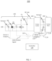
- a system 100 includes a boost converter 102, a 3-phase inverter 104, and a 3-phase motor or load 106.
- the boost converter 102 includes the power supply 108, the inductor L1, the diode D1, the gate drive GD, the switch S1, and the DC link capacitor C1.
- the power supply 108 is electrically coupled to the inductor L1 and increases the voltage of the inductor L1 when the switch S1 is closed.
- the gate driver GD is coupled to the control terminal of the switch S1 which is under the control of a control signal of a controller 120.
- the controller 120 may enter the boost mode of operation based on the power level of the power supply 108. For example, thresholds for various voltage levels and power levels can be used to determine when the system 100 should enter the boost mode or rectification mode of operation.
- the operation of the 3-phase inverter can be interrupted when the demand from the load 106 exceeds the capability of the power supply 108.
- the power supply 108 is a DC source such as a battery.
- the power supply 108 may be another type of DC source.
- the boost converter 102 can operate in a rectification mode to rectify the power from the power supply 108 to provide the required voltage for the load 106. In such a mode, the switch S2 is controlled open to prevent the boost operation of the boost converter 102.
- a first voltage sensor (“Sensor1”) is electrically coupled in parallel with the power supply 108 and detects the voltage that is output from the power supply 108.
- the "Sensor1 Output" from Sensor1 represents the voltage level of the power supply voltage level, is provided to the controller 120.
- a second voltage sensor (“Sensor2”) and a third voltage (“Sensor3) are electrically coupled in parallel to the AB phases and the BC phases that are output of the 3-phase inverter 104, respectively.
- Sensor2 and Sensor 3 provide the voltage levels V_AB and V_BC to the controller 120.
- the voltage levels V_AB and V_BC of the 3-phase inverter 104 are provided to an ABC/dq transformation module 122.
- the ABC/dq transformation module 122 can be incorporated in the controller 120.
- the DQ transform is used to simplify the analysis of 3-phase synchronous machines or to simplify calculations for the control of 3-phase inverters.
- the transformation transfers 3-phase stator and rotor quantities into a single rotating reference frame to eliminate the effect of time-varying inductances and transform the system into a linear time-invariant system.
- the transformation can be performed in the controller 120 and can be executed in either hardware, software, or any combination thereof.
- the controller 120 can compare the voltage levels at the 3-phase inverter output and the power supply 108.
- a comparator 124 receives the output from the ABC/dq transformation module 122 and compares the voltage level of the power supply 108 indicated by the Sensor1 Output.
- the comparator 124 can be performed in the controller 120.
- the comparator 124 can compare the absolute value of the voltage (Vdq) with a threshold voltage of the power supply 108. For example, the absolute value of the voltage
- the DCM control signal can be transmitted from the controller 120 to control the DCM switch S2.
- the DCM control signal can open and close the switch S2 to operate the boost converter 102 in a rectification mode (non-boosting mode) and a boost mode to increase the voltage to meet the demand of the load 106.
- the boost converter 102 can be operated in the rectification mode (non-boosting mode) when the DCM switch S2 is controlled to remain open, and the boost converter 102 can be operated in the boost mode when the DCM switch S2 is closed.
- the switch S1 can be switched according to the PWM signals provided from the controller 120 and is operable to increase or step-up the input voltage to a desired level when are operated in the boost mode.
- FIG. 2 illustrates a non-limiting example of the 3-phase inverter 104 shown in FIG. 1 .
- the 3-phase inverter 104 includes 3 pairs of transistors (T1, T4), (T2, T5), (T3, T6), where each pair of transistors are operated in a complementary fashion to generate a corresponding 3-phase output (A, B, C), respectively.
- the transistors T1-T6 may be implemented as metal-oxide semiconductor devices or other controllable devices such as bipolar junction transistors (BJT) devices, IGBT devices, or the like.
- BJT bipolar junction transistors
- Each of the control terminals of the transistors T1-T6 are electrically coupled to the controller 120.
- the arrangement of the 3-phase inverter can be operated using known techniques such as pulse-width modulation (PWM). It should be understood that other arrangement can be used to generate the 3-phase output.
- PWM pulse-width modulation
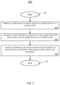
- FIG. 3 depicts a flowchart of a method 300 for controlling the boost converter 102 in accordance with one or more embodiments of the invention.
- the method 300 can be implemented in a system 100 such as that shown in FIG. 1 .
- the method 300 starts at block 302 and proceeds to block 304 which provides for receiving, at a controller, a voltage level of a power supply and a voltage level of a 3-phase inverter.
- the controller 120 can monitor and receive the output voltage levels corresponding to the DC battery source and the output of the 3-phase inverter. It can be appreciated the controller 120 can also receive other information from current sensors and/or voltage sensors arranged in the system 100.
- the controller 120 can determine the power from the voltage and current information obtained from the sensors coupled to the power supply, 3-phase inverter, load, etc.
- the boost operation of the boost converter 102 can be implemented based on exceeding a power threshold or a comparison between the output level and a percentage of the power supply.
- the voltage of the load or the motor approaches the rectified voltage of the boost converter 102 when operated in a rectification mode (non-boosting mode).
- the boost converter switches from the rectification mode to the boost mode, to supply the voltage that is demanded by the load.
- the stable operation of the boost converter 102 is enabled to avoid the DCM that is responsive to the detected conditions.
- Block 306 compares a power threshold to at least one of: the voltage level of the power supply and the voltage level of the 3-phase inverter.
- a threshold level that is 95% of power supply level can be used.
- the threshold can include a higher threshold such as 96%, 97%, etc. or a lower threshold such as 94%, 93%, etc. It should be understood the threshold is not intended to be limited by any of the examples described herein but can be any configurable to any value based upon the application.
- the 3-phase output of the 3-phase inverter is transformed to the dq-frame of reference. The transformation allows the controller 120 to compare the transformed 3-phase output to the DC voltage of the power supply 108. In one or more embodiments of the invention, the controller 120 can determine whether the output of the 3-phase inverter exceeds the threshold voltage of the power supply 108 or is below the threshold voltage.
- Block 308 controls an operation of the boost converter circuit to operate in a boost mode or a rectification mode based at least in part on the comparison.
- the controller when the voltage of the power supply or the voltage of the 3-phase inverter is greater than the power threshold, the controller is configured to operate the boost converter circuit in the boost mode.
- the controller 120 provides a control signal to the lo-side DCM switch to close the switch to enable the boost mode of the boost converter 102 to increase the voltage provided to the 3-phase inverter 104 and load 106.
- the boost converter 102 is prevented from entering DCM.
- the controller When the power of the power supply or the 3-phase inverter is less than the power threshold, the controller is configured to operate the boost converter circuit in the rectification mode. In the rectification mode, the controller holds the DCM switch open to prevent the PWM signals from entering the boost mode.
- the comparison further comprises comparing the voltage level of the power supply to at least one of: the voltage of the 3-phase inverter and a voltage level of a load.
- the controller 120 is configured to operate the boost converter in the boost mode.
- the controller is configured to operate the boost converter in the rectification mode.
- the method 300 ends at block 310. It should be understood that additional steps or a different sequence of steps can be included in various embodiments of the invention and is not intended to be limited by the steps shown in FIG. 3 .
- the technical effects and benefits include reducing losses from the battery-DC bus power electronics interface.
- the stability of the eTRU inverter is improved at low loads and the overall efficiency is improved by operating the boost converter in the rectification mode and the boost mode.
- the technical effects and benefits include being operable with variable-speed operation.
Landscapes
- Engineering & Computer Science (AREA)
- Power Engineering (AREA)
- Dc-Dc Converters (AREA)
Applications Claiming Priority (1)
| Application Number | Priority Date | Filing Date | Title |
|---|---|---|---|
| US202163272746P | 2021-10-28 | 2021-10-28 |
Publications (1)
| Publication Number | Publication Date |
|---|---|
| EP4175164A1 true EP4175164A1 (de) | 2023-05-03 |
Family
ID=83690162
Family Applications (1)
| Application Number | Title | Priority Date | Filing Date |
|---|---|---|---|
| EP22200848.4A Pending EP4175164A1 (de) | 2021-10-28 | 2022-10-11 | Aufwärtswandlerzustandssteuerung |
Country Status (3)
| Country | Link |
|---|---|
| US (1) | US12328080B2 (de) |
| EP (1) | EP4175164A1 (de) |
| CN (1) | CN116054621A (de) |
Citations (2)
| Publication number | Priority date | Publication date | Assignee | Title |
|---|---|---|---|---|
| EP2922192A1 (de) * | 2014-03-18 | 2015-09-23 | Kabushiki Kaisha Yaskawa Denki | Stromwandler, Stromerzeugungssystem, Vorrichtung zur Steuerung eines Stromwandlers und Verfahren zur Steuerung eines Stromwandlers |
| US9929636B2 (en) * | 2014-02-19 | 2018-03-27 | Mitsubishi Electric Corporation | DC power-supply device, motor drive device including the same, and refrigeration-cycle application device including the motor drive device |
Family Cites Families (26)
| Publication number | Priority date | Publication date | Assignee | Title |
|---|---|---|---|---|
| US5414613A (en) | 1993-08-20 | 1995-05-09 | Rem Technologies, Incorporated | Soft switching active snubber for semiconductor circuit operated in discontinuous conduction mode |
| US6115274A (en) | 1999-06-01 | 2000-09-05 | Lucent Technologies Inc. | Frequency modulation controller for single-switch, polyphase, DCM boost converter and method of operation thereof |
| US8080973B2 (en) | 2008-10-22 | 2011-12-20 | General Electric Company | Apparatus for energy transfer using converter and method of manufacturing same |
| US20140265945A1 (en) | 2013-03-15 | 2014-09-18 | Infineon Technologies Austria Ag | Electric Drive System |
| CN105052027A (zh) | 2013-04-02 | 2015-11-11 | 三菱电机株式会社 | 电力变换装置以及制冷空气调节装置 |
| US10771001B2 (en) | 2015-09-11 | 2020-09-08 | Invertedpower Pty Ltd | Controller for an inductive load having one or more inductive windings |
| US10239407B2 (en) | 2016-01-25 | 2019-03-26 | Ford Global Technologies, Llc | Variable carrier switching frequency control of variable voltage converter |
| US9931944B2 (en) | 2016-03-22 | 2018-04-03 | Ford Global Technologies, Llc | Variable voltage convert system with reduced bypass diode conduction |
| US9960687B2 (en) | 2016-06-06 | 2018-05-01 | General Electric Company | System and method for a DC/DC converter |
| US10148212B2 (en) | 2017-01-06 | 2018-12-04 | Thermo King Corporation | DC to DC converter sourcing variable DC link voltage |
| CN108347167B (zh) | 2017-01-25 | 2021-07-13 | 通用电气公司 | 用于软切换dc—dc转换器的系统和方法 |
| JP6725446B2 (ja) * | 2017-03-23 | 2020-07-15 | 株式会社東芝 | 巻線形誘導機の制御システム、および制御方法 |
| US10381967B2 (en) | 2017-05-17 | 2019-08-13 | Toyota Motor Engineering & Manufacturing North America, Inc. | Simplified power conversion systems for vehicles |
| KR102433999B1 (ko) | 2017-08-24 | 2022-08-19 | 현대자동차주식회사 | 모터 구동 및 배터리 충전 장치 및 차량 |
| US10840807B2 (en) | 2017-09-22 | 2020-11-17 | Thermo King Corporation | DC to DC converter sourcing variable DC link voltage |
| AU2019239085A1 (en) | 2018-03-22 | 2020-10-08 | Tae Technologies, Inc. | Systems and methods for power management and control |
| US10348221B1 (en) | 2018-04-25 | 2019-07-09 | Schlage Lock Company Llc | Dynamic energy harvesting and variable harvesting force system |
| CN112313101B (zh) | 2018-09-28 | 2023-09-01 | 开利公司 | 带有能量存储系统和外部dc电力来源的运输制冷单元 |
| US11945284B2 (en) | 2018-09-28 | 2024-04-02 | Carrier Corporation | Transportation refrigeration unit with DC generator charging of prime mover energy storage device |
| WO2020068502A1 (en) | 2018-09-28 | 2020-04-02 | Carrier Corporation | Transportation refrigeration unit with external dc generator power source |
| US10870333B2 (en) | 2018-10-31 | 2020-12-22 | Thermo King Corporation | Reconfigurable utility power input with passive voltage booster |
| US10926610B2 (en) | 2018-10-31 | 2021-02-23 | Thermo King Corporation | Methods and systems for controlling a mild hybrid system that powers a transport climate control system |
| CN111509695B (zh) | 2019-01-31 | 2025-09-02 | 开利公司 | 电力模块装置和运输冷藏系统 |
| EP3769984B1 (de) | 2019-07-24 | 2023-05-24 | Schmitz Cargobull AG | Transportkältemaschine zum kühlen eines laderaums eines nutzfahrzeugs |
| US11203262B2 (en) | 2019-09-09 | 2021-12-21 | Thermo King Corporation | Transport climate control system with an accessory power distribution unit for managing transport climate control loads |
| US11211872B1 (en) * | 2020-09-28 | 2021-12-28 | Delta Electronics, Inc. | Power-factor-correction rectifiers with soft switching |
-
2022
- 2022-10-07 US US17/962,004 patent/US12328080B2/en active Active
- 2022-10-11 EP EP22200848.4A patent/EP4175164A1/de active Pending
- 2022-10-27 CN CN202211325772.3A patent/CN116054621A/zh active Pending
Patent Citations (2)
| Publication number | Priority date | Publication date | Assignee | Title |
|---|---|---|---|---|
| US9929636B2 (en) * | 2014-02-19 | 2018-03-27 | Mitsubishi Electric Corporation | DC power-supply device, motor drive device including the same, and refrigeration-cycle application device including the motor drive device |
| EP2922192A1 (de) * | 2014-03-18 | 2015-09-23 | Kabushiki Kaisha Yaskawa Denki | Stromwandler, Stromerzeugungssystem, Vorrichtung zur Steuerung eines Stromwandlers und Verfahren zur Steuerung eines Stromwandlers |
Non-Patent Citations (1)
| Title |
|---|
| RAVI KIRAN S ET AL: "Voltage control of variable speed SEIG with Z-Source inverter", INDUSTRIAL ELECTRONICS AND APPLICATIONS (ICIEA), 2012 7TH IEEE CONFERENCE ON, IEEE, 18 July 2012 (2012-07-18), pages 844 - 849, XP032268507, ISBN: 978-1-4577-2118-2, DOI: 10.1109/ICIEA.2012.6360842 * |
Also Published As
| Publication number | Publication date |
|---|---|
| CN116054621A (zh) | 2023-05-02 |
| US20230134793A1 (en) | 2023-05-04 |
| US12328080B2 (en) | 2025-06-10 |
Similar Documents
| Publication | Publication Date | Title |
|---|---|---|
| US7830036B2 (en) | Power electronic module pre-charge system and method | |
| EP2661802B1 (de) | Bidirektionaler tief-hochsetzsteller | |
| EP2144357A1 (de) | Geschaltetes gleichstrom-gleichstrom-umsetzungssystem zum isolieren von hochfrequenz und verfahren dafür | |
| US9312692B2 (en) | System for charging an energy store, and method for operating the charging system | |
| US11683001B2 (en) | Motor driving apparatus | |
| US20130038140A1 (en) | Switching circuit | |
| US11223237B2 (en) | High efficiency power converting apparatus and control method | |
| US10924024B2 (en) | Regenerative power conversion system with inverter and converter | |
| US9397581B2 (en) | Power conversion apparatus that provides a release path for inductive energy accumulated in an inductive load | |
| US20120025609A1 (en) | Very high efficiency uninterruptible power supply | |
| US11114949B2 (en) | Inverter control board that is configured so that a detection circuit is appropriately arranged | |
| EP3471264B1 (de) | Leistungsausgabevorrichtung | |
| EP3051676A1 (de) | Schaltvorrichtung, stromumwandlungsvorrichtung, motorantriebsvorrichtung, gebläse, verdichter, klimaanlage, kühlschrank und gefrierschrank | |
| US12206401B2 (en) | Drive device to drive semiconductor element, semiconductor device, and power conversion device | |
| EP4190542A1 (de) | Leistungsumwandlungsvorrichtung und metallverarbeitungsvorrichtung | |
| EP2120320B1 (de) | Gleichstromversorgung | |
| EP4175164A1 (de) | Aufwärtswandlerzustandssteuerung | |
| US10734900B2 (en) | Converter device, motor drive device, refrigerator, air conditioner, and heat-pump water heater | |
| CN111835215A (zh) | 转换器电路、电力转换系统以及电动机驱动装置 | |
| WO2015116931A1 (en) | Unidirectional matrix converter with regeneration system | |
| JP2020031507A (ja) | 電力変換装置及び、これを用いたインバータ装置 | |
| US12308774B2 (en) | Electric motor system | |
| US12095396B2 (en) | Reduced motor magnetic losses via reduction of temporal harmonics by control of DC link voltage | |
| EP4693877A1 (de) | Wechselrichtervorrichtung, motorantriebsvorrichtung damit und kühlvorrichtung | |
| US12341412B2 (en) | Direct-current power supply, refrigeration cycler, air conditioner, and refrigerator |
Legal Events
| Date | Code | Title | Description |
|---|---|---|---|
| PUAI | Public reference made under article 153(3) epc to a published international application that has entered the european phase |
Free format text: ORIGINAL CODE: 0009012 |
|
| STAA | Information on the status of an ep patent application or granted ep patent |
Free format text: STATUS: THE APPLICATION HAS BEEN PUBLISHED |
|
| AK | Designated contracting states |
Kind code of ref document: A1 Designated state(s): AL AT BE BG CH CY CZ DE DK EE ES FI FR GB GR HR HU IE IS IT LI LT LU LV MC ME MK MT NL NO PL PT RO RS SE SI SK SM TR |
|
| STAA | Information on the status of an ep patent application or granted ep patent |
Free format text: STATUS: REQUEST FOR EXAMINATION WAS MADE |
|
| 17P | Request for examination filed |
Effective date: 20231103 |
|
| RBV | Designated contracting states (corrected) |
Designated state(s): AL AT BE BG CH CY CZ DE DK EE ES FI FR GB GR HR HU IE IS IT LI LT LU LV MC ME MK MT NL NO PL PT RO RS SE SI SK SM TR |
|
| STAA | Information on the status of an ep patent application or granted ep patent |
Free format text: STATUS: EXAMINATION IS IN PROGRESS |
|
| 17Q | First examination report despatched |
Effective date: 20241024 |