EP4175376A1 - Positionierungsverfahren, vorrichtung und system für eine übertragungsvorrichtung sowie speichermedium und elektronische vorrichtung - Google Patents
Positionierungsverfahren, vorrichtung und system für eine übertragungsvorrichtung sowie speichermedium und elektronische vorrichtung Download PDFInfo
- Publication number
- EP4175376A1 EP4175376A1 EP21833048.8A EP21833048A EP4175376A1 EP 4175376 A1 EP4175376 A1 EP 4175376A1 EP 21833048 A EP21833048 A EP 21833048A EP 4175376 A1 EP4175376 A1 EP 4175376A1
- Authority
- EP
- European Patent Office
- Prior art keywords
- meta
- coordinate
- preset direction
- target
- reflection coefficient
- Prior art date
- Legal status (The legal status is an assumption and is not a legal conclusion. Google has not performed a legal analysis and makes no representation as to the accuracy of the status listed.)
- Pending
Links
Images



Classifications
-
- H—ELECTRICITY
- H04—ELECTRIC COMMUNICATION TECHNIQUE
- H04B—TRANSMISSION
- H04B7/00—Radio transmission systems, i.e. using radiation field
- H04B7/14—Relay systems
- H04B7/15—Active relay systems
- H04B7/155—Ground-based stations
- H04B7/15528—Control of operation parameters of a relay station to exploit the physical medium
-
- H—ELECTRICITY
- H04—ELECTRIC COMMUNICATION TECHNIQUE
- H04W—WIRELESS COMMUNICATION NETWORKS
- H04W64/00—Locating users or terminals or network equipment for network management purposes, e.g. mobility management
-
- H—ELECTRICITY
- H04—ELECTRIC COMMUNICATION TECHNIQUE
- H04W—WIRELESS COMMUNICATION NETWORKS
- H04W64/00—Locating users or terminals or network equipment for network management purposes, e.g. mobility management
- H04W64/006—Locating users or terminals or network equipment for network management purposes, e.g. mobility management with additional information processing, e.g. for direction or speed determination
-
- G—PHYSICS
- G01—MEASURING; TESTING
- G01S—RADIO DIRECTION-FINDING; RADIO NAVIGATION; DETERMINING DISTANCE OR VELOCITY BY USE OF RADIO WAVES; LOCATING OR PRESENCE-DETECTING BY USE OF THE REFLECTION OR RERADIATION OF RADIO WAVES; ANALOGOUS ARRANGEMENTS USING OTHER WAVES
- G01S5/00—Position-fixing by co-ordinating two or more direction or position line determinations; Position-fixing by co-ordinating two or more distance determinations
- G01S5/02—Position-fixing by co-ordinating two or more direction or position line determinations; Position-fixing by co-ordinating two or more distance determinations using radio waves
-
- G—PHYSICS
- G01—MEASURING; TESTING
- G01S—RADIO DIRECTION-FINDING; RADIO NAVIGATION; DETERMINING DISTANCE OR VELOCITY BY USE OF RADIO WAVES; LOCATING OR PRESENCE-DETECTING BY USE OF THE REFLECTION OR RERADIATION OF RADIO WAVES; ANALOGOUS ARRANGEMENTS USING OTHER WAVES
- G01S5/00—Position-fixing by co-ordinating two or more direction or position line determinations; Position-fixing by co-ordinating two or more distance determinations
- G01S5/02—Position-fixing by co-ordinating two or more direction or position line determinations; Position-fixing by co-ordinating two or more distance determinations using radio waves
- G01S5/0205—Details
-
- G—PHYSICS
- G01—MEASURING; TESTING
- G01S—RADIO DIRECTION-FINDING; RADIO NAVIGATION; DETERMINING DISTANCE OR VELOCITY BY USE OF RADIO WAVES; LOCATING OR PRESENCE-DETECTING BY USE OF THE REFLECTION OR RERADIATION OF RADIO WAVES; ANALOGOUS ARRANGEMENTS USING OTHER WAVES
- G01S5/00—Position-fixing by co-ordinating two or more direction or position line determinations; Position-fixing by co-ordinating two or more distance determinations
- G01S5/02—Position-fixing by co-ordinating two or more direction or position line determinations; Position-fixing by co-ordinating two or more distance determinations using radio waves
- G01S5/0205—Details
- G01S5/0221—Receivers
-
- G—PHYSICS
- G01—MEASURING; TESTING
- G01S—RADIO DIRECTION-FINDING; RADIO NAVIGATION; DETERMINING DISTANCE OR VELOCITY BY USE OF RADIO WAVES; LOCATING OR PRESENCE-DETECTING BY USE OF THE REFLECTION OR RERADIATION OF RADIO WAVES; ANALOGOUS ARRANGEMENTS USING OTHER WAVES
- G01S5/00—Position-fixing by co-ordinating two or more direction or position line determinations; Position-fixing by co-ordinating two or more distance determinations
- G01S5/02—Position-fixing by co-ordinating two or more direction or position line determinations; Position-fixing by co-ordinating two or more distance determinations using radio waves
- G01S5/0273—Position-fixing by co-ordinating two or more direction or position line determinations; Position-fixing by co-ordinating two or more distance determinations using radio waves using multipath or indirect path propagation signals in position determination
-
- G—PHYSICS
- G01—MEASURING; TESTING
- G01S—RADIO DIRECTION-FINDING; RADIO NAVIGATION; DETERMINING DISTANCE OR VELOCITY BY USE OF RADIO WAVES; LOCATING OR PRESENCE-DETECTING BY USE OF THE REFLECTION OR RERADIATION OF RADIO WAVES; ANALOGOUS ARRANGEMENTS USING OTHER WAVES
- G01S5/00—Position-fixing by co-ordinating two or more direction or position line determinations; Position-fixing by co-ordinating two or more distance determinations
- G01S5/02—Position-fixing by co-ordinating two or more direction or position line determinations; Position-fixing by co-ordinating two or more distance determinations using radio waves
- G01S5/04—Position of source determined by a plurality of spaced direction-finders
-
- G—PHYSICS
- G01—MEASURING; TESTING
- G01S—RADIO DIRECTION-FINDING; RADIO NAVIGATION; DETERMINING DISTANCE OR VELOCITY BY USE OF RADIO WAVES; LOCATING OR PRESENCE-DETECTING BY USE OF THE REFLECTION OR RERADIATION OF RADIO WAVES; ANALOGOUS ARRANGEMENTS USING OTHER WAVES
- G01S5/00—Position-fixing by co-ordinating two or more direction or position line determinations; Position-fixing by co-ordinating two or more distance determinations
- G01S5/02—Position-fixing by co-ordinating two or more direction or position line determinations; Position-fixing by co-ordinating two or more distance determinations using radio waves
- G01S5/10—Position of receiver fixed by co-ordinating a plurality of position lines defined by path-difference measurements, e.g. omega or decca systems
-
- H—ELECTRICITY
- H01—ELECTRIC ELEMENTS
- H01Q—ANTENNAS, i.e. RADIO AERIALS
- H01Q15/00—Devices for reflection, refraction, diffraction or polarisation of waves radiated from an antenna, e.g. quasi-optical devices
- H01Q15/0006—Devices acting selectively as reflecting surface, as diffracting or as refracting device, e.g. frequency filtering or angular spatial filtering devices
- H01Q15/0093—Devices acting selectively as reflecting surface, as diffracting or as refracting device, e.g. frequency filtering or angular spatial filtering devices having a fractal shape
-
- H—ELECTRICITY
- H04—ELECTRIC COMMUNICATION TECHNIQUE
- H04B—TRANSMISSION
- H04B7/00—Radio transmission systems, i.e. using radiation field
- H04B7/02—Diversity systems; Multi-antenna system, i.e. transmission or reception using multiple antennas
- H04B7/04—Diversity systems; Multi-antenna system, i.e. transmission or reception using multiple antennas using two or more spaced independent antennas
- H04B7/04013—Intelligent reflective surfaces
-
- H—ELECTRICITY
- H04—ELECTRIC COMMUNICATION TECHNIQUE
- H04B—TRANSMISSION
- H04B7/00—Radio transmission systems, i.e. using radiation field
- H04B7/14—Relay systems
- H04B7/145—Passive relay systems
-
- H—ELECTRICITY
- H04—ELECTRIC COMMUNICATION TECHNIQUE
- H04W—WIRELESS COMMUNICATION NETWORKS
- H04W24/00—Supervisory, monitoring or testing arrangements
- H04W24/08—Testing, supervising or monitoring using real traffic
Definitions
- Embodiments of the present disclosure relate to the field of communications, in particular to a positioning method, device and system for a transmitting device, and a storage medium and an electronic device.
- NLOS positioning methods include a Line-Of-Sight (LOS) reconstruction positioning method, an NLOS weighted positioning method, a Time of Arrival (TOA) positioning method based on a combination of line-of-sight reconstruction and smoothing, and a positioning method based on inequality constraints.
- the NLOS is converted into the LOS according to a mirror principle, or influences of NLOS components are reduced through stochastic methods by the coordination between multiple base stations.
- fingerprint maps or positioning methods based on a Global Positioning System (GPS) in the related art require the deployment of another positioning system and related accessories, which increases the cost and limits the implementation in some scenarios. It can be seen that in the related art, the use of multiple systems and the support from other related technologies are required during positioning, and a terminal cannot be positioned by means of the characteristics of a meta-surface.
- GPS Global Positioning System
- the embodiments of the present disclosure provide a positioning method, device and system for a transmitting device, and a storage medium and an electronic device, which can at least the technical problem in the related art that a terminal cannot be positioned by means of characteristics of a meta-surface.
- a positioning method for a transmitting device includes the following operations.
- Control information is determined by a receiving device, wherein the control information includes temporal information and control direction information; the control direction information is used for instructing a meta-surface control unit to adjust a reflection coefficient of a meta-surface to a target reflection coefficient corresponding to a preset direction, so that a beam in a direction from the receiving device to the meta-surface forms on the meta-surface a reflected beam in the preset direction;
- the preset direction is a direction indicated by preset direction information corresponding to a target time period, and the preset direction points to a target area;
- the temporal information includes the target time period; and the control direction information includes the preset direction information.
- a pilot signal is transmitted to the meta-surface by a transmitting device, wherein the transmitting device is located in the target area.
- the control information is sent to the meta-surface control unit by the receiving device, wherein the control information is used for instructing the meta-surface control unit to adjust the reflection coefficient of the meta-surface to the target reflection coefficient corresponding to the preset direction within the target time period.
- a signal measurement result corresponding to the preset direction is determined, and the transmitting device is positioned according to the preset direction and the signal measurement result, wherein the signal measurement result is a measurement result obtained by the receiving device measuring a received target pilot signal; the target pilot signal is received by the receiving device after reflected by the meta-surface whose reflection coefficient is adjusted to the target reflection coefficient; and the pilot signals transmitted by the transmitting device include the target pilot signal.
- a positioning device for a transmitting device which includes: a determining module, a transmitting module, a controlling module and a positioning module.
- the determining module is configured to determine the control information by the receiving device.
- the control information includes the temporal information and the control direction information.
- the control direction information is used for instructing the meta-surface control unit to adjust the reflection coefficient of the meta-surface to the target reflection coefficient corresponding to the preset direction, so that the beam in the direction from the receiving device to the meta-surface forms on the meta-surface the reflected beam in the preset direction.
- the preset direction is a direction indicated by preset direction information corresponding to a target time period, and the preset direction points to the target area.
- the temporal information includes the target time period.
- the control direction information includes the preset direction information.
- the transmitting module is configured to transmit the pilot signal to the meta-surface by the transmitting device.
- the transmitting device is located in the target area.
- the controlling module is configured to send the control information to the meta-surface control unit by the receiving device.
- the control information is used for instructing the meta-surface control unit to adjust the reflection coefficient of the meta-surface to the target reflection coefficient corresponding to the preset direction within the target time period.
- the positioning module is configured to determine the signal measurement result corresponding to the preset direction, and position the transmitting device according to the preset direction and the signal measurement result.
- the signal measurement result is a measurement result obtained by the receiving device measuring a received target pilot signal.
- the target pilot signal is received by the receiving device after reflected by the meta-surface whose reflection coefficient is adjusted to the target reflection coefficient.
- the pilot signals transmitted by the transmitting device include the target pilot signal.
- the temporal information includes the target time period.
- the control direction information includes the preset direction information.
- the transmitting device is configured to transmit the pilot signal to the meta-surface.
- the transmitting device is located in the target area.
- the receiving device is further configured to send the control information to the meta-surface control unit.
- the control information is used for instructing the meta-surface control unit to adjust the reflection coefficient of the meta-surface to the target reflection coefficient corresponding to the preset direction within the target time period.
- the receiving device is further configured to determine the signal measurement result corresponding to the preset direction.
- the positioning node is configured to position the transmitting device according to the preset direction and the signal measurement result.
- the signal measurement result is a measurement result obtained by the receiving device measuring a received target pilot signal.
- the target pilot signal is received by the receiving device after reflected by the meta-surface whose reflection coefficient is adjusted to the target reflection coefficient.
- the pilot signals transmitted by the transmitting device include the target pilot signal.
- an electronic device which includes a memory and a processor.
- the memory stores a computer program.
- the processor is configured to run the computer program, so as to perform operations in any of the above method embodiments.
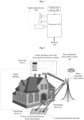
- FIG. 1 is a structural block diagram of hardware of an electronic device for a positioning method for a transmitting device in an embodiment of the present disclosure.
- the electronic device may include one or more (only one is shown in Fig. 1 ) processors 102 (the processor 102 may include, but is not limited to, a micro controller unit (MCU) or a field programmable gate array (FPGA) and other processing devices) and a memory 104 configured to store data.
- MCU micro controller unit
- FPGA field programmable gate array
- the above electronic device may further include a transceiver device 106 with a communication function and an input/output device 108.
- a structure shown in Fig. 1 is merely schematic and does not pose a limitation on a structure of the above electronic device.
- the electronic device may further include assemblies more or fewer than those shown in Fig. 1 , or have a configuration different from that shown in Fig. 1 .
- the memory 104 may be configured to store a computer program such as a software program and module of an application, for example, a computer program corresponding to a positioning method for a transmitting device in an embodiment of the present disclosure, and the processor 102 executes various functional applications and data processing by running the computer program stored in the memory 104, that is, achieves the above method.
- the memory 104 may include a high-speed random access memory, and may further include a non-volatile memory, for example, one or more magnetic storage devices, flash memories, or other non-volatile solid-state memories.
- the memory 104 may further include a memory remotely arranged with respect to the processor 102, and the remote memory may be connected with the electronic device by means of a network. Examples of the above network include, but are not limited to, the internet, enterprise intranets, local area networks, mobile communication networks, and combinations thereof.
- the embodiments of the present disclosure may run on the network architecture shown in Fig. 2 .
- the network architecture includes: a transmitting device (for example, a terminal, Fig. 2 shows that there are two transmitting devices, namely transmitting device A (i.e. terminal A) and transmitting device B (i.e. terminal B)), a beam-adjustable meta-surface control unit (i.e. corresponding to the meta-surface control unit in the embodiments of the present disclosure, or called meta-surface control device or meta-surface control apparatus), a beam-adjustable meta-surface (i.e. the meta-surface in the embodiments of the present disclosure, also called reconfigurable meta-surface), and a receiving device (for example, a base station).
- a transmitting device for example, a terminal
- Fig. 2 shows that there are two transmitting devices, namely transmitting device A (i.e. terminal A) and transmitting device B (i.e. terminal B)
- a beam-adjustable meta-surface control unit
- the receiving device includes a radio frequency unit or antenna.
- the receiving device is configured to plan, configure, and receive a specific radio signal.
- the receiving device receives the specific radio signal transmitted by the transmitting device and reflected by the meta-surface (i.e. a target pilot signal in the embodiments of the present disclosure).
- the meta-surface control unit is configured to control a reflection coefficient of each electromagnetic unit (or called electromagnetic reflection unit) in the meta-surface.
- the meta-surface is composed of several groups of electromagnetic units with controllable reflection coefficient. By controlling the reflection coefficient of each electromagnetic element, the meta-surface can form a predetermined reflected beam antenna pattern (that is, a reflected beam in a preset direction is formed on the meta-surface).
- the transmitting device is configured to transmit a specific radio signal (i.e.
- a positioning method for a transmitting device running in the above network architecture is provided.
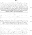
- Fig. 3 is a flowchart of a positioning method for a transmitting device according to an embodiment of the present disclosure. As shown in Fig. 3 , the flow includes the following operations.
- control information is determined by a receiving device.
- the control information includes temporal information and control direction information.
- the control direction information is used for instructing a meta-surface control unit to adjust a reflection coefficient of a meta-surface to a target reflection coefficient corresponding to a preset direction, so that a beam in a direction from the receiving device to the meta-surface forms on the meta-surface a reflected beam in the preset direction.
- the preset direction is a direction indicated by preset direction information corresponding to a target time period, and the preset direction points to a target area.
- the temporal information includes the target time period.
- the control direction information includes the preset direction information.
- control information is sent to the meta-surface control unit by the receiving device.
- the control information is used for instructing the meta-surface control unit to adjust the reflection coefficient of the meta-surface to the target reflection coefficient corresponding to the preset direction within the target time period.
- a signal measurement result corresponding to the preset direction is determined, and the transmitting device is positioned according to the preset direction and the signal measurement result.
- the signal measurement result is a measurement result obtained by the receiving device measuring a received target pilot signal.
- the target pilot signal is received by the receiving device after reflected by the meta-surface whose reflection coefficient is adjusted to the target reflection coefficient.
- the pilot signals transmitted by the transmitting device include the target pilot signal.
- control information is determined by a receiving device, wherein the control information includes temporal information and control direction information; the control direction information is used for instructing a meta-surface control unit to adjust a reflection coefficient of a meta-surface to a target reflection coefficient corresponding to a preset direction, so that a beam in a direction from the receiving device to the meta-surface forms on the meta-surface a reflected beam in the preset direction; the preset direction is a direction indicated by preset direction information corresponding to a target time period, and the preset direction points to a target area; the temporal information includes the target time period; and the control direction information includes the preset direction information.
- a pilot signal is transmitted to the meta-surface by a transmitting device, wherein the transmitting device is located in the target area.
- the control information is sent to the meta-surface control unit by the receiving device, wherein the control information is used for instructing the meta-surface control unit to adjust the reflection coefficient of the meta-surface to the target reflection coefficient corresponding to the preset direction within the target time period.
- a signal measurement result corresponding to the preset direction is determined, and the transmitting device is positioned according to the preset direction and the signal measurement result, wherein the signal measurement result is a measurement result obtained by the receiving device measuring a received target pilot signal; the target pilot signal is received by the receiving device after reflected by the meta-surface whose reflection coefficient is adjusted to the target reflection coefficient; and the pilot signals transmitted by the transmitting device include the target pilot signal. Therefore, the technical problem in the related art that a terminal cannot be positioned by means of characteristics of a meta-surface can be solved, thereby achieving the effect of using the characteristics of a meta-surface to position a terminal.
- S304 and S306 are interchangeable, that is, S306 may be executed first and then S304.
- the operation that the control information is determined by the receiving device includes that the control information is determined according to a target scanning area.
- the operation that the control information is determined according to the target scanning area includes that: multiple pieces of preset direction information are determined according to multiple sub-areas obtained by dividing the target area, and multiple target time periods are determined according to the multiple pieces of preset direction information.
- the multiple pieces of preset direction information are in one-to-one correspondence with the multiple sub-areas.
- the temporal information includes the multiple target time periods.
- the multiple target time periods are in one-to-one correspondence with the multiple pieces of preset direction information.
- each piece of preset direction information among multiple pieces of preset direction information is determined as a respective one of the multiple preset directions
- the temporal information is determined according to the multiple pieces of preset direction information.
- the temporal information includes the multiple target time periods, and the multiple target time periods are in one-to-one correspondence with the multiple pieces of preset direction information.
- the target area may be divided into multiple sub-areas by the receiving device.
- the target area is divided into sub-area 1, sub-area 2, sub-area 3, etc.
- the preset direction information corresponding to each sub-area is determined according to the multiple sub-areas, such as preset direction information 1, preset direction information 2, and preset direction information 3.
- the preset direction information is used for instructing the meta-surface control unit to adjust a reflection coefficient of each electromagnetic unit of the meta-surface, so that the reflected beam formed on the meta-surface points to the sub-area corresponding to the preset direction information.
- the reflected beam is the reflected beam (also called virtual reflected beam) formed on the meta-surface by the beam in the direction from the receiving device to the meta-surface.
- the target time period may be a time period corresponding to a time slot number (i.e. the serial number of a time slot), and the sequence information may be a set composed of the time periods corresponding to the time slot numbers (i.e. the time periods corresponding to the corresponding time slots), that is, the temporal information includes the time periods corresponding to multiple time slots in chronological order.
- the temporal information includes the multiple target time periods
- the control direction information includes multiple pieces of preset direction information
- each target time period in the temporal information corresponds to each piece of preset direction information in the control direction information.
- the meta-surface control unit may be instructed to adjust the reflection coefficient of the meta-surface to the target reflection coefficient within a target time period; and when the next target time period of the target time period arrives (for example, the start time of the next target time period arrives), the reflection coefficient of the meta-surface is adjusted to the next target reflection coefficient by the meta-surface control unit.
- the next target reflection coefficient is the reflection coefficient corresponding to the next preset direction
- the next preset direction is the direction indicated by the preset direction information corresponding to the next target time period.
- the reflection coefficient of the meta-surface is adjusted to the corresponding reflection coefficient by the meta-surface control unit within a certain target time period in the temporal information.
- the corresponding reflection coefficient is the reflection coefficient corresponding to the preset direction indicated by the preset direction information corresponding to the target time period.
- the method may further include the following operations: the target reflection coefficient is determined by the meta-surface control unit according to the preset direction information; and a reflection coefficient of each electromagnetic unit of the meta-surface is adjusted to the target reflection coefficient by the meta-surface control unit within the target time period, so as to adjust the reflection coefficient of the meta-surface to the target reflection coefficient.
- the reflection coefficient of each electromagnetic unit includes at least one of amplitude, phase and polarization. That is, the reflection coefficient of each electromagnetic unit may be any combination of amplitude, phase and polarization.
- the method may further include the following operations: the target reflection coefficient is determined by the meta-surface control unit according to the input parameter; and a reflection coefficient of each electromagnetic unit of the meta-surface is adjusted to the target reflection coefficient by the meta-surface control unit within the target time period, so as to adjust the reflection coefficient of the meta-surface to the target reflection coefficient; or, in a case where the preset direction information is the target reflection coefficient corresponding to the preset direction, after the control information is sent to the meta-surface control unit by the receiving device, the method may further include the following operation: a reflection coefficient of each electromagnetic unit of the meta-surface is adjusted to the target reflection coefficient by the meta-surface control unit within the target time period, so as to adjust the reflection coefficient of the meta-surface to the target reflection coefficient.
- the meta-surface control unit is further configured to adjust, at the beam control start time, the reflection coefficient of the meta-surface to the target reflection coefficient corresponding to the first preset direction according to the first target time period in the temporal information.
- the first preset direction is the direction indicated by the preset direction information corresponding to the first target time period.
- the target time periods in the temporal information form a continuous period of time
- the start time of the first target time period in the temporal information is the beam control start time
- the end time of the last target time period is the beam control end time
- the end time of each intermediate target time period i.e. the target time period between the first target time period and the last target time period
- the temporal information includes target time period 1 to target time period 3
- the end time of the target time period 1 is the start time of the target time period 2
- the end time of the target time period 2 is the start time of the target time period 3
- the start time of the target time period 1 is the beam control start time
- the end time of the target time period 3 is the beam control end time.
- the target time period and the corresponding relationship of the pilot signals transmitted within the target time period which are recorded by the transmitting device are consistent with the target time period and the corresponding relationship of the target pilot signals received within the target time period which are recorded by the receiving device.
- the operation that the signal measurement result corresponding to the preset direction is determined may include the following operations: the target time period corresponding to each signal measurement result in a signal measurement result set is determined, wherein the signal measurement result set includes the signal measurement result corresponding to the preset direction; and according to the target time period, the preset direction indicated by the preset direction information corresponding to the target time period is determined, and the signal measurement result corresponding to the target time period is determined as the signal measurement result corresponding to the preset direction.
- the operation that the transmitting device is positioned according to the preset direction and the signal measurement result may include the following operations: according to the preset direction and a position and height of the meta-surface, position coordinates (xi, yi) of the reflected beam corresponding to each preset direction in the target area are determined, and a value of the signal measurement result corresponding to the preset direction is determined as a z-coordinate zi corresponding to the position coordinates (xi, yi), wherein i is an identifier of the reflected beam corresponding to the preset direction; Gaussian function fitting is performed according to a coordinate range of the target area, the position coordinates (xi, yi) and the corresponding z-coordinate zi to obtain a fitted Gaussian function, and a positioning result of positioning the transmitting device is determined according to coordinates corresponding to a vertex of the fitted Gaussian function.
- the x-coordinate is in the range of [xs, xe]
- the y-coordinate is in the range of [ys, ye]
- xs, xe, ys and ye are all real numbers, xe>xs, and ye>ys
- the x-coordinate range and the y-coordinate range of the target area are sampled respectively according to the preset coordinate interval to obtain the sampled x-coordinate set and y-coordinate set, then in the above embodiment, xs ⁇ xw ⁇ xe, and ys ⁇ yp ⁇ ye; and in the obtained positioning result, xs ⁇ xt ⁇ xe, and ys ⁇ yt ⁇ ye.
- the coordinates (i.e. the corresponding input when the Gaussian function is at its maximum value) corresponding to the vertexes (i.e. the maximum value of the Gaussian function, also the maximum value of the Gaussian curve corresponding to the Gaussian function) of two one-dimensional Gaussian functions may be determined respectively by fitting two one-dimensional Gaussian functions (namely fitting two one-dimensional Gaussian curves respectively to obtain two one-dimensional Gaussian functions, each one-dimensional Gaussian function corresponding to a Gaussian curve), so as to determine the position coordinates of the transmitting device (that is, determine the positioning result).
- the operation that the z-coordinate zw corresponding to each x-coordinate xw in the x-coordinate set is determined from the z-coordinate zi corresponding to the position coordinates (xi, yi), and a z-coordinate zp corresponding to each y-coordinate yp in the y-coordinate set is determined from the z-coordinate zi corresponding to the position coordinates (xi, yi) may include the following operations: the z-coordinates corresponding to all the position coordinates whose x-coordinate is xw in the position coordinates (xi, yi) are determined, and the maximum value of the z-coordinates corresponding to all the position coordinates whose x-coordinate is xw is determined as the z-coordinate zw corresponding to the x-coordinate xw; and the z-coordinates corresponding to all the position coordinates whose y-coordinate is yp in the position coordinates (xi,
- the operation that the transmitting device is positioned according to the preset direction and the signal measurement result may include the following operations: according to the preset direction and a position and height of the meta-surface, position coordinates (xi, yi) of the reflected beam corresponding to each preset direction in the target area are determined, and a value of the signal measurement result corresponding to the preset direction is determined as a z-coordinate zi corresponding to the position coordinates (xi, yi), wherein i is an identifier of the reflected beam corresponding to the preset direction; two-dimensional Gaussian function fitting is performed according to a coordinate set (xi, yi, zi) composed of the position coordinates (xi, yi) and the z-coordinate zi to obtain a fitted two-dimensional Gaussian function; coordinates (xt, yt) corresponding to a vertex of the two-dimensional Gaussian function are determined, and the coordinates (xt, yt) are determined as a positioning result of
- the obtained positioning result is as follows: xs ⁇ xt ⁇ xe, and ys ⁇ yt ⁇ ye.
- the position coordinates of the transmitting device may be determined by the two-dimensional Gaussian function fitting (that is, the Gaussian surface fitting is performed).
- the fitting may be realized by using the least square method and the minimum mean square error method.
- the method may include the following operation: the target direction information is determined according to a positioning result of positioning the transmitting device, the target direction information being used for instructing the meta-surface control unit to control a reflection coefficient of each electromagnetic unit of the meta-surface according to the target direction information, so that the reflected beam formed on the meta-surface by the radio signal transmitted by the receiving device points to the transmitting device.
- the receiving device sends the target direction information to the meta-surface control unit, so as to instruct the meta-surface control unit to control the reflection coefficient of the meta-surface according to the target direction information, so that the reflected beam formed on the meta-surface by the radio signal transmitted by the receiving device (i.e. the base station) points to the transmitting device, and thus the radio signal transmitted by the base station can reach the terminal accurately.
- the receiving device i.e. the base station
- the positioning method for a transmitting device in the above embodiment is explained with an example, but the example is not intended to limit the technical solution of the embodiments of the present disclosure.
- the beam-adjustable meta-surface also called reconfigurable meta-surface, namely the meta-surface in the above embodiment
- the characteristics of the meta-surface can be used to achieve the accurate alignment of the target beam direction, so that a deployment scheme of the meta-surface is self-complete; besides, in the non-direct diameter areas with enhanced meta-surface coverage, the terminal can be positioned accurately. That is, in the embodiments of the present disclosure, with the deployment of the meta-surface, a non-direct diameter terminal can be positioned by use of a single base station.
- the following nodes are mainly involved: a receiving device and a transmitting device.
- the receiving device is configured to determine beam scanning planning, and send relevant information of the beam scanning planning to the transmitting device by means of the radio frequency unit.
- the relevant information of the beam scanning planning includes a beam scanning interval (the beam scanning interval is the time interval between the beam control start time and the beam control end time in the above embodiments), a specific pilot sequence of the transmitting device (i.e. the target pilot signal in the above embodiments), and related time-frequency resources.
- the operation that the beam scanning planning is determined refers to a process in which the receiving device divides the target area into grids or plans the direction of the target beam, and converts two-dimensional space domain planning of the target area into one-dimensional time domain planning. For example, the receiving device determines the grids corresponding to a chronological order (i.e.
- the receiving device also sends the beam control start time and the beam control end time to the transmitting device.
- the transmitting device is configured to transmit the target pilot signal according to the time-frequency resources configured by the receiving device in the beam scanning interval.
- the beam is adjusted by means of the radio frequency unit in the transmitting device, and the transmitted beam is aligned to the meta-surface (the target pilot signal is transmitted to the meta-surface).
- the pilot sequence i.e. the target pilot signal in the above embodiment
- transmitted by the transmitting device is a coding sequence that is known in advance by both the transmitting device and the receiving device and can be used for distinguishing different transmitting devices.
- the coding sequence has good characteristics of autocorrelation and cross-correlation.
- the receiving device is further configured to control the meta-surface by the meta-surface control unit in the beam scanning interval, that is, adjust, within the target time period, a reflection coefficient of each electromagnetic unit of the meta-surface to the target reflection coefficient corresponding to the target time period, so as to realize the scanning of the target area in the beam scanning interval.
- the receiving device is further configured to identify the transmitting device and measure the radio signal strength (i.e. the signal measurement result in the above embodiment) based on the received pilot sequence. Multiple transmitting devices may simultaneously transmit the pilot signals at the same time.
- the operation that the meta-surface is controlled by the meta-surface control unit may include the following operation: the receiving device sends the control information to the meta-surface control unit through an interface between the receiving device and the meta-surface control unit.
- the control information includes, but is not limited to, the following: the beam control start time, the adjustment and control direction of a beam, the target reflection coefficient of each electromagnetic unit, the input parameter for determining the target reflection coefficient of each electromagnetic unit, the temporal information, the beam control end time, etc.
- the control information may be a beam target to which adjustment is about to be performed or adjustment and control instructions for each electromagnetic unit of the meta-surface. When these instructions are applied to each electromagnetic unit, the electromagnetic unit can change or adjust the reflection coefficient (also called input reflection coefficient), so that the reflection coefficient of each electromagnetic unit in the meta-surface is adjusted to the target reflection coefficient corresponding to the target time period.
- the receiving device may determine the control information (including the preset direction information used for making the beam in the direction from the receiving device to the meta-surface form on the meta-surface the reflected beam in the preset direction) in advance, and after determining the control information, control the meta-surface by the meta-surface control unit in the beam scanning interval according to the control information.
- the receiving device When controlling the meta-surface according to the control information, the receiving device does not transmit a signal to the meta-surface, and there is no signal transmitted to the meta-surface by the receiving device.
- the purpose of adjusting the reflection coefficient of the meta-surface to the target reflection coefficient is to adjust the state of the meta-surface to a state of generating a virtual reflected beam along the preset direction, and the virtual reflected beam is the reflected beam formed on the meta-surface when the radio signal is transmitted to the meta-surface by means of an analog receiving device, that is, the radio signal transmitted by the receiving device to the meta-surface is an analog signal, and the receiving device does not actually need to transmit the radio signal. Therefore, in the embodiments of the present disclosure, after the receiving device determines the control information, the receiving device does not need to transmit the radio signal to the meta-surface when the transmitting device is positioned.
- a virtual main beam reflected by the meta-surface i.e. the above virtual reflected beam
- can point to different target directions i.e. the preset direction in the above embodiments
- the predetermined time period i.e. the target time period in the temporal information in the above embodiments
- the receiving device measures and records the radio signal quality of the target pilot signal transmitted by each transmitting device in the beam scanning interval, that is, in the beam scanning interval, the receiving device measures the signal quality of the received target pilot signal based on the known target pilot signal, and records each signal quality and the corresponding target time period. That is, the signal measurement result set composed of the signal measurement results recorded by the receiving device is the radio signal quality in chronological order (that is, the signal measurement result set is time sequence data), and each signal measurement result corresponds to the adjustment and control time sequence of the beam of the meta-surface (that is, the temporal information composed of the target time periods corresponding to the signal measurement results in the signal measurement result set is consistent with the temporal information used for controlling the meta-surface).
- the receiving device is further configured to estimate the target beam direction and position the transmitting device based on the measurement results of the receiving device (i.e. the signal measurement results in the above embodiments).
- the operation that the target beam direction is estimated and the transmitting device is positioned based on the measurement results of the receiving device may include the following operations: (1) based on the measurement results of the receiving device and the adjustment and control time sequence of the beam of the meta-surface, when it is determined that main adjustment and control beam of the meta-surface points to different directions, the receiving device measures the radio signal quality for a certain terminal; and (2) the position of the terminal and the target beam direction are estimated based on the radio signal quality of different directions of the main adjustment and control beam.
- the exemplary implementation of operation (2) may be performed in the receiving device or other network positioning devices.
- one-dimensional time data may be transformed into two-dimensional space data based on the beam direction of the meta-surface and related measurement results.
- the position of the terminal is determined through two-dimensional surface fitting algorithms.
- the two-dimensional surface fitting algorithms include, but are not limited to, two-dimensional Gaussian distribution surface, least square method, minimum mean square error method, etc., or two independent Gaussian curves reduced to one dimension are used for fitting.
- Fig. 4 is a plane diagram of a deployment scenario of a meta-surface according to an embodiment of the present disclosure, showing a beam scanning area (i.e. the target area in the above embodiments) and the beam-adjustable meta-surface (i.e. the meta-surface in the above embodiments).
- deployment parameters of the receiving device i.e. the base station where a radio frequency receiving unit of the base station in Fig. 4 is located
- the receiving device i.e. the base station where a radio frequency receiving unit of the base station in Fig. 4 is located
- the deployment parameters of the meta-surface are as follows:
- the parameters of the transmitting device and the meta-surface are configured as follows:
- the positioning accuracy of the positioning method for the transmitting device in the embodiments of the present disclosure is tested, with reference to the transmitting device A at the position coordinates [78, 88] (in meters) and the transmitting device B at the position coordinates [76, 98] (in meters) in the target area, the positioning accuracy of the positioning method in the embodiments of the present disclosure is tested.
- the positioning method may include the following operations.
- the receiving device determines the beam scanning planning: from the first time slot (the time period corresponding to the first time slot is the first target time period, and the start time of the first target time period also corresponds to the time of starting the adjustment and control of the beam in the above embodiments) to the 180th time slot (i.e. the 180th target time period, which is also the last target time period in the temporal information, and the end time of the last target time period also corresponds to the time of ending the adjustment and control of the beam in the above embodiments), beam scanning in the beam scanning area (i.e. the target area in the above embodiments) in Fig. 4 is performed, and the receiving device sends the relevant information of the beam scanning planning to the transmitting device by means of the radio frequency unit.
- the first time slot the time period corresponding to the first time slot is the first target time period, and the start time of the first target time period also corresponds to the time of starting the adjustment and control of the beam in the above embodiments
- the 180th time slot i.e. the 180th target time period
- the relevant information includes: each target time period in the temporal information (the start time of the first target time period in the temporal information (also the time of starting the adjustment and control of the beam), the end time of the last target time period (i.e. the time of ending the adjustment and control of the beam), and the time period from the beam control start time and the beam control end time are adjustment and control intervals of the beam), the specific pilot sequence of the transmitting device (i.e. the target pilot signal corresponding to the transmitting device), and the related time-frequency resources.
- the radio frequency unit of the transmitting device adjusts the beam to align to the meta-surface, and transmits the pilot sequence signal (i.e. the target pilot signal in the above embodiments) in the beam scanning interval according to the time-frequency resources configured by the receiving device.
- the pilot sequence signals of different transmitting devices can be distinguished through frequency division or code division.
- the receiving device controls the direction of the virtual beam of the meta-surface by the meta-surface control unit.
- the frequency of updating the beam scanning direction of the meta-surface is each time slot. In a certain time slot (i.e. the time period corresponding to the time slot), the virtual reflected beam reaches the beam scanning area along a certain preset direction. After each update, the beam will be aligned to the next new predetermined direction (that is, the preset direction in the above embodiments).
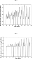
- the receiving device measures and records the radio signal quality of the wireless pilot signal transmitted by the relevant transmitting device in the beam scanning interval, and the results are shown in Fig. 5 and Fig. 6.
- Fig. 5 shows signal receiving strength obtained by the receiving device after measuring the received target pilot signal which is transmitted by the transmitting device A.
- Fig. 6 shows signal receiving strength obtained by the receiving device after measuring the received target pilot signal which is transmitted by the transmitting device B.
- the horizontal axes in Fig. 5 and Fig. 6 are the time slots arranged in sequence. Because each time slot lasts for certain duration, each time slot may correspond to a time period (i.e. the target time period in the above embodiments).
- the k-th target time period i.e. the time period corresponding to the k-th time slot
- the temporal information is the time period between t0+(k-1)a and t0+ka, where t0 is the beam control start time (in milliseconds), and k is an integer greater than or equal to 1.
- the target beam direction is estimated and the transmitting device is positioned based on the measurement results of the receiving device.
- the format of the measurement results in a measurement period for a certain transmitting device is as follows: (slotNo indicates a time slot number, namely each target time period in the above embodiments, RxPwr indicates a receiving level, namely the signal measurement result in the above embodiments) slotNo 1: RxPwr -130; (that is, within the first target time period (i.e. the time period corresponding to the first time slot), the signal strength level of the received target pilot signal is - 130dbm) ... slotNo 57: RxPwr -87.31;
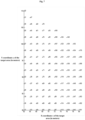
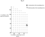
- a networking positioning node (which may be a receiving device or a network positioning device different from the receiving device in the network) maps the time slot number to the target beam direction, and transforms the one-dimensional time data in Fig. 7 obtained for the transmitting device A into the two-dimensional space data ( Fig. 8 ) in combination with the position and height of the center of the meta-surface (i.e. the position and height of the meta-surface in the above embodiments), at the same time, maps the measurement result to the ground of the beam scanning area, seeing Fig. 9 (that is, Fig. 9 is the plan of Fig. 8 ).
- the number next to each dot "•" in Fig. 7 indicates the time slot number, for example, the two annotations •31 and •47 in the second line of Fig.
- FIG. 7 where "37" and “47” respectively represent that the corresponding time slot numbers are 31 and 47.
- FIG. 7 the position coordinates corresponding to each time slot number can be determined.
- the horizontal axis and longitudinal axis in Fig. 8 represent the x-coordinate and the y-coordinate of the target area respectively, and the vertical axis (z axis) represents the received signal quality.
- a predicted position of the transmitting device is a positioning result obtained by positioning the transmitting device (i.e. the coordinates in the positioning result).
- the horizontal axis and the longitudinal axis in Fig. 9 represent the x-coordinate and the y-coordinate of the target area respectively.
- Each dot "•" in Fig. 9 represents the presence of received signal quality, and the specific received signal quality is shown in the z-coordinates in Fig. 8 .
- the one-dimensional time data obtained by measuring the received pilot signal transmitted by the transmitting device B is transformed into the two-dimensional space data (as shown in Fig. 10 ), at the same time, the measurement result is mapped to the ground of the beam scanning area, seeing Fig. 11 (that is, Fig. 11 is the plan of Fig. 10 ).
- X coordinate and Y coordinate of the transmitting device are independently estimated by using a dimensionality reduction method, as follows:
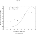
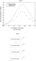
- the obtained coordinate set in the X-axis direction and the corresponding radio signal quality are the measured data shown in Fig. 12 .
- the radio signal quality is assigned to its segment according to the segmentation result in the Y direction, and the coordinate set of the center points of the segments on the Y axis is [80, 82, 84 ..., 110].
- the strongest radio signal received quality in each segment is determined as the unique dimensionality reduction receiving level in this segment (that is, for each y-coordinate yp in the y-coordinate set, zp corresponding to the yp is determined in a specific determining mode similar to the above processing mode of the X-axis direction), and the result is as follows:
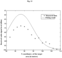
- the obtained coordinate set in the Y-axis direction and the corresponding radio signal quality are the measured data shown in Fig. 13 .
- the following operation is performed for all the two-dimensional data in Fig. 10 (that is, the following operation is performed for the radio signal received quality obtained by measuring the received target pilot signal transmitted by the transmitting device B): according to the segmentation result in the X-axis direction, for the set [62, 64, 66, ..., 80] composed of the coordinates corresponding to the center points of the segments on the X axis, the dimensionality reduction receiving level corresponding to the coordinates of each center point is determined (in an exemplary embodiment, the strongest radio signal received quality in each segment is determined as the unique dimensionality reduction receiving level in this segment, that is, for the coordinate xw of a certain center point, the maximum value (i.e. zw) of the radio signal received quality (i.e. the receiving level) corresponding to this coordinate xw is determined), and the result is as follows:
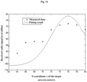
- the obtained coordinate set in the X-axis direction and the corresponding radio signal quality are the measured data shown in Fig. 14 .
- the radio signal quality is assigned to its segment according to the segmentation result in the Y direction, and the coordinate set of the center points of the segments on the Y axis is [80, 82, 84 ..., 110].
- the strongest radio signal received quality in each segment is determined as the unique dimensionality reduction receiving level in this segment (that is, for each y-coordinate yp in the y-coordinate set, zp corresponding to the yp is determined), and the result is as follows:
- the obtained coordinate set in the Y-axis direction and the corresponding radio signal quality are the measured data shown in Fig. 15 .
- the one-dimensional Gaussian function is selected as a fitting curve to perform one-dimensional Gaussian curve fitting (i.e. one-dimensional Gaussian function fitting) in the X-axis and Y-axis directions.
- the parameters of the one-dimensional Gaussian function i.e. the Gaussian curve corresponding to the one-dimensional Gaussian function, referring to a fitting result in Fig. 12
- the x coordinate i.e. xt in the above embodiments
- the center point i.e. the vertex, the maximum value of the function
- the Gaussian curve corresponding to the one-dimensional Gaussian function, referring to a fitting result in Fig. 13 ) corresponding to the Y-axis direction may be determined by the least square fitting, and the y coordinate (i.e. yt in the above embodiments) corresponding to the center point of the function is determined.
- the position coordinates of the transmitting device A obtained by positioning is [76.2230 97.6619]m
- the positioning error between the position coordinates and the real coordinate position of the transmitting A as the reference target is: 0.405m.
- the results of performing the one-dimensional Gaussian curve fitting in the X-axis direction and the Y-axis direction are shown respectively in Fig. 14 and Fig. 15 .
- the position coordinates of the transmitting device B obtained by positioning is [77.7978 88.7517]m, and the positioning error between the position coordinates and the real coordinate position of the transmitting B as the reference target is: 0.50378m. It can be seen from the above that a more accurate positioning result can be obtained by using the positioning method in the embodiments of the present disclosure.
- the computer software product is stored in a storage medium (for example, an ROM/an RAM, a magnetic disk, and a compact disc) and includes a number of instructions to make a computer device (which can be a personal computer, a server or a network device, etc.) perform all or part of the method in each embodiment of the present disclosure.
- a storage medium for example, an ROM/an RAM, a magnetic disk, and a compact disc
- An embodiment also provides a positioning device for a transmitting device, which is configured to implement the above embodiments and exemplary implementations.
- the embodiments which have been elaborated will not be repeated here.
- the term "module” used below can realize a combination of software and/or hardware with an intended function. Although the device described in the following embodiment is realized through software better, the realization through hardware or a combination of software and hardware is possible and conceived.
- Fig. 16 is a structural block diagram of a positioning device for a transmitting device according to an embodiment of the present disclosure. As shown in Fig. 16 , the positioning device includes: a determining module 211, a transmitting module 213, a controlling module 215, and a positioning module 217.
- the determining module 211 is configured to determine the control information by the receiving device.
- the control information includes the temporal information and the control direction information.
- the control direction information is used for instructing the meta-surface control unit to adjust the reflection coefficient of the meta-surface to the target reflection coefficient corresponding to the preset direction, so that the beam in the direction from the receiving device to the meta-surface forms on the meta-surface the reflected beam in the preset direction.
- the preset direction is a direction indicated by preset direction information corresponding to a target time period, and the preset direction points to the target area.
- the temporal information includes the target time period.
- the control direction information includes the preset direction information.
- the transmitting module 213 is configured to transmit the pilot signal to the meta-surface by the transmitting device.
- the transmitting device is located in the target area.
- the controlling module 215 is configured to send the control information to the meta-surface control unit by the receiving device.
- the control information is used for instructing the meta-surface control unit to adjust the reflection coefficient of the meta-surface to the target reflection coefficient corresponding to the preset direction within the target time period.
- the positioning module 217 is configured to determine the signal measurement result corresponding to the preset direction, and position the transmitting device according to the preset direction and the signal measurement result.
- the signal measurement result is a measurement result obtained by the receiving device measuring a received target pilot signal.
- the target pilot signal is received by the receiving device after reflected by the meta-surface whose reflection coefficient is adjusted to the target reflection coefficient.
- the pilot signals transmitted by the transmitting device include the target pilot signal.
- control information is determined by a receiving device, wherein the control information includes temporal information and control direction information; the control direction information is used for instructing a meta-surface control unit to adjust a reflection coefficient of a meta-surface to a target reflection coefficient corresponding to a preset direction, so that a beam in a direction from the receiving device to the meta-surface forms on the meta-surface a reflected beam in the preset direction; the preset direction is a direction indicated by preset direction information corresponding to a target time period, and the preset direction points to a target area; the temporal information includes the target time period; and the control direction information includes the preset direction information.
- a pilot signal is transmitted to the meta-surface by a transmitting device, wherein the transmitting device is located in the target area.
- the control information is sent to the meta-surface control unit by the receiving device, wherein the control information is used for instructing the meta-surface control unit to adjust the reflection coefficient of the meta-surface to the target reflection coefficient corresponding to the preset direction within the target time period.
- a signal measurement result corresponding to the preset direction is determined, and the transmitting device is positioned according to the preset direction and the signal measurement result, wherein the signal measurement result is a measurement result obtained by the receiving device measuring a received target pilot signal; the target pilot signal is received by the receiving device after reflected by the meta-surface whose reflection coefficient is adjusted to the target reflection coefficient; and the pilot signals transmitted by the transmitting device include the target pilot signal. Therefore, the technical problem in the related art that a terminal cannot be positioned by means of characteristics of a meta-surface can be solved, thereby achieving the effect of using the characteristics of a meta-surface to position a terminal.
- An embodiment also provides a positioning system for a transmitting device, which is configured to implement the above embodiments and exemplary implementations. The embodiments which have been elaborated will not be repeated here.
- the system includes: a transmitting device, a receiving device, a meta-surface control unit, a meta-surface and a positioning node.
- the receiving device is configured to determine the control information.
- the control information includes the temporal information and the control direction information.
- the control direction information is used for instructing the meta-surface control unit to adjust the reflection coefficient of the meta-surface to the target reflection coefficient corresponding to the preset direction, so that the beam in the direction from the receiving device to the meta-surface forms on the meta-surface the reflected beam in the preset direction.
- the preset direction is a direction indicated by preset direction information corresponding to a target time period, and the preset direction points to the target area.
- the temporal information includes the target time period.
- the control direction information includes the preset direction information.
- the transmitting device is configured to transmit the pilot signal to the meta-surface.
- the transmitting device is located in the target area.
- the receiving device is further configured to send the control information to the meta-surface control unit.
- the control information is used for instructing the meta-surface control unit to adjust the reflection coefficient of the meta-surface to the target reflection coefficient corresponding to the preset direction within the target time period.
- the receiving device is further configured to determine the signal measurement result corresponding to the preset direction.
- the positioning node is configured to position the transmitting device according to the preset direction and the signal measurement result.
- the signal measurement result is a measurement result obtained by the receiving device measuring a received target pilot signal.
- the target pilot signal is received by the receiving device after reflected by the meta-surface whose reflection coefficient is adjusted to the target reflection coefficient.
- the pilot signals transmitted by the transmitting device include the target pilot signal.
- control information is determined by a receiving device, wherein the control information includes temporal information and control direction information; the control direction information is used for instructing a meta-surface control unit to adjust a reflection coefficient of a meta-surface to a target reflection coefficient corresponding to a preset direction, so that a beam in a direction from the receiving device to the meta-surface forms on the meta-surface a reflected beam in the preset direction; the preset direction is a direction indicated by preset direction information corresponding to a target time period, and the preset direction points to a target area; the temporal information includes the target time period; and the control direction information includes the preset direction information.
- a pilot signal is transmitted to the meta-surface by a transmitting device, wherein the transmitting device is located in the target area.
- the control information is sent to the meta-surface control unit by the receiving device, wherein the control information is used for instructing the meta-surface control unit to adjust the reflection coefficient of the meta-surface to the target reflection coefficient corresponding to the preset direction within the target time period.
- a signal measurement result corresponding to the preset direction is determined, and the transmitting device is positioned according to the preset direction and the signal measurement result, wherein the signal measurement result is a measurement result obtained by the receiving device measuring a received target pilot signal; the target pilot signal is received by the receiving device after reflected by the meta-surface whose reflection coefficient is adjusted to the target reflection coefficient; and the pilot signals transmitted by the transmitting device include the target pilot signal. Therefore, the technical problem in the related art that a terminal cannot be positioned by means of characteristics of a meta-surface can be solved, thereby achieving the effect of using the characteristics of a meta-surface to position a terminal.
- the positioning node may be the receiving device or other positioning devices in the network.
- the receiving device is further configured to determine the control information according to the target scanning area.
- the receiving device is configured to determine the control information in a following manner. Multiple pieces of preset direction information are determined according to multiple sub-areas obtained by dividing the target area, and multiple target time periods are determined according to the multiple pieces of preset direction information. The multiple pieces of preset direction information are in one-to-one correspondence with the multiple sub-areas.
- the temporal information includes the multiple target time periods. The multiple target time periods are in one-to-one correspondence with the multiple pieces of preset direction information.
- each piece of preset direction information among multiple pieces of preset direction information is determined as a respective one of the multiple preset directions
- multiple target time periods are determined according to the multiple pieces of preset direction information.
- the temporal information includes the multiple target time periods, and the multiple target time periods are in one-to-one correspondence with the multiple pieces of preset direction information.
- the meta-surface control unit is configured to: determine the target reflection coefficient by according to the preset direction information; and adjust a reflection coefficient of each electromagnetic unit of the meta-surface to the target reflection coefficient within the target time period, so as to adjust the reflection coefficient of the meta-surface to the target reflection coefficient.
- the reflection coefficient of each electromagnetic unit includes at least one of amplitude, phase and polarization.
- the receiving device is further configured to: determine the target time period corresponding to each signal measurement result in the signal measurement result set, wherein the signal measurement result set includes the signal measurement result corresponding to the preset direction; and according to the target time period, determine the preset direction indicated by the preset direction information corresponding to the target time period, and determine the signal measurement result corresponding to the target time period as the signal measurement result corresponding to the preset direction.
- the positioning node is further configured to: according to the preset direction and a position and height of the meta-surface, determine position coordinates (xi, yi) of the reflected beam corresponding to each preset direction in the target area, and determine a value of the signal measurement result corresponding to the preset direction as a z-coordinate zi corresponding to the position coordinates (xi, yi), wherein i is an identifier of the reflected beam corresponding to the preset direction; perform the Gaussian function fitting according to a coordinate range of the target area, the position coordinates (xi, yi) and the corresponding z-coordinate zi to obtain the fitted Gaussian function, and determine the positioning result of positioning the transmitting device according to coordinates corresponding to a vertex of the fitted Gaussian function.
- the positioning node is further configured to: sample the x-coordinate range and the y-coordinate range of the target area respectively according to the preset coordinate interval to obtain the sampled x-coordinate set and y-coordinate set; determine a z-coordinate zw corresponding to each x-coordinate xw in the x-coordinate set from the z-coordinate zi corresponding to the position coordinates (xi, yi), and determine a z-coordinate zp corresponding to each y-coordinate yp in the y-coordinate set from the z-coordinate zi corresponding to the position coordinates (xi, yi), wherein both w and p are positive integers in an interval [1, n], and n is the number of samples sampled; perform the one-dimensional Gaussian function fitting according to a coordinate set (xw, zw) composed of the x-coordinate set and the z-coordinate zw corresponding to each x-coordinate
- the positioning node is further configured to: according to the preset direction and a position and height of the meta-surface, determine position coordinates (xi, yi) of the reflected beam corresponding to each preset direction in the target area, and determine a value of the signal measurement result corresponding to the preset direction as a z-coordinate zi corresponding to the position coordinates (xi, yi), wherein i is an identifier of the reflected beam corresponding to the preset direction; fit the two-dimensional Gaussian function according to a coordinate set (xi, yi, zi) composed of the position coordinates (xi, yi) and the z-coordinate zi to obtain the fitted two-dimensional Gaussian function; determine coordinates (xt, yt) corresponding to a vertex of the two-dimensional Gaussian function, and determine the coordinates (xt, yt) as a positioning result of positioning the transmitting device, xt being an x-coordinate within the x-coordinate range
- the positioning node is further configured to: determine the target direction information according to a positioning result of positioning the transmitting device, the target direction information being used for instructing the meta-surface control unit to control a reflection coefficient of each electromagnetic unit of the meta-surface according to the target direction information, so that the reflected beam formed on the meta-surface by the radio signal transmitted by the receiving device points to the transmitting device.
- the method may further include the following operations: the target reflection coefficient is determined by the meta-surface control unit according to the input parameter; and a reflection coefficient of each electromagnetic unit of the meta-surface is adjusted to the target reflection coefficient by the meta-surface control unit within the target time period, so as to adjust the reflection coefficient of the meta-surface to the target reflection coefficient; or, in a case where the preset direction information is the target reflection coefficient corresponding to the preset direction, after the control information is sent to the meta-surface control unit by the receiving device, the method may further include the following operation: a reflection coefficient of each electromagnetic unit of the meta-surface is adjusted to the target reflection coefficient by the meta-surface control unit within the target time period, so as to adjust the reflection coefficient of the meta-surface to the target reflection coefficient.
- control information may further include at least one of following information: the time of starting the adjustment and control of the beam, which is used for instructing the meta-surface control unit to start controlling a reflection coefficient of each electromagnetic unit of the meta-surface at the time of starting the adjustment and control of the beam; and the time of ending the adjustment and control of the beam, which is used for instructing the meta-surface control unit to end up controlling the reflection coefficient of each electromagnetic unit of the meta-surface at the time of ending the adjustment and control of the beam.
- each of the above modules may be realized by software or hardware.
- the each of the above modules may be realized by, but not limited to, the following way: all of the above modules are in the same processor; or, the above modules are respectively in different processors in form of any combination.
- An embodiment of the present disclosure also provides a computer-readable storage medium, in which a computer program is stored.
- the computer program is configured to perform, when running, the operations in any of the above method embodiments.
- the computer-readable storage media may include, but are not limited to, a USB flash disk, an ROM, an RAM, a mobile hard disk, a magnetic disk, a compact disc, and other media capable of storing the computer program.
- An embodiment of the present disclosure also provides an electronic device, which includes a memory and a processor.
- the memory stores a computer program.
- the processor is configured to run the computer program, so as to execute the operations in any of the above method embodiments.
- the electronic device may also include a transceiver device and an input/output device.
- the transceiver device is connected with the processor, and the input/output device is connected with the processor.
- modules and operations of the present disclosure may be implemented by a general-purpose computing device, and they may be centralized in a single computing device or distributed on a network composed of multiple computing devices; they may be implemented by a program code which is capable of being executed by the computing device, so that they may be stored in a storage device and executed by the computing device; and in some situations, the presented or described operations may be executed in an order different from that described here; or they are made into integrated circuit modules, respectively; or multiple modules and operations of them are made into a single integrated circuit module to realize. Therefore, the present disclosure is not limited to any particular combination of hardware and software.
Landscapes
- Engineering & Computer Science (AREA)
- Computer Networks & Wireless Communication (AREA)
- Signal Processing (AREA)
- Physics & Mathematics (AREA)
- General Physics & Mathematics (AREA)
- Radar, Positioning & Navigation (AREA)
- Remote Sensing (AREA)
- Radar Systems Or Details Thereof (AREA)
- Mobile Radio Communication Systems (AREA)
- Signal Processing For Digital Recording And Reproducing (AREA)
Applications Claiming Priority (2)
| Application Number | Priority Date | Filing Date | Title |
|---|---|---|---|
| CN202010615392.8A CN111867054B (zh) | 2020-06-30 | 2020-06-30 | 发射装置的定位方法及装置、系统、存储介质和电子装置 |
| PCT/CN2021/093459 WO2022001402A1 (zh) | 2020-06-30 | 2021-05-12 | 发射装置的定位方法及装置、系统、存储介质和电子装置 |
Publications (2)
| Publication Number | Publication Date |
|---|---|
| EP4175376A1 true EP4175376A1 (de) | 2023-05-03 |
| EP4175376A4 EP4175376A4 (de) | 2023-12-27 |
Family
ID=72988827
Family Applications (1)
| Application Number | Title | Priority Date | Filing Date |
|---|---|---|---|
| EP21833048.8A Pending EP4175376A4 (de) | 2020-06-30 | 2021-05-12 | Positionierungsverfahren, vorrichtung und system für eine übertragungsvorrichtung sowie speichermedium und elektronische vorrichtung |
Country Status (7)
| Country | Link |
|---|---|
| US (1) | US12136968B2 (de) |
| EP (1) | EP4175376A4 (de) |
| JP (1) | JP7853925B2 (de) |
| KR (1) | KR20230031337A (de) |
| CN (1) | CN111867054B (de) |
| WO (1) | WO2022001402A1 (de) |
| ZA (1) | ZA202301503B (de) |
Families Citing this family (9)
| Publication number | Priority date | Publication date | Assignee | Title |
|---|---|---|---|---|
| CN111867054B (zh) | 2020-06-30 | 2025-10-17 | 中兴通讯股份有限公司 | 发射装置的定位方法及装置、系统、存储介质和电子装置 |
| CN112735111B (zh) | 2020-12-16 | 2022-04-08 | 中兴通讯股份有限公司 | 智能面板调控方法、装置、系统、智能面板和存储介质 |
| CN117280634A (zh) * | 2021-05-13 | 2023-12-22 | 高通股份有限公司 | 用于采用智能反射表面进行交叉链路干扰管理的网络信息交换 |
| CN113804961B (zh) * | 2021-10-11 | 2024-04-12 | 中国电信股份有限公司 | 智能表面设备和系统,以及控制方法、装置和系统 |
| CN114126060B (zh) * | 2021-10-22 | 2025-05-30 | 中国信息通信研究院 | 一种无线通信系统节点传输状态信令指示方法和设备 |
| CN113947730B (zh) * | 2021-11-26 | 2025-09-23 | 长光禹辰信息技术与装备(青岛)有限公司 | 遥感数据识别方法、装置、电子设备及可读存储介质 |
| CN114143810B (zh) * | 2021-11-29 | 2023-04-28 | 中国电信股份有限公司 | 智能表面控制方法及其相关设备 |
| CN114423077B (zh) * | 2022-01-13 | 2023-09-08 | 中国电子科技集团公司第七研究所 | 基于智能超表面的4d内生安全室内定位方法及其定位系统 |
| CN115754895B (zh) * | 2022-09-07 | 2025-11-11 | 东南大学 | 基于人工神经网络和时空编码超表面的来波方向估计方法 |
Family Cites Families (22)
| Publication number | Priority date | Publication date | Assignee | Title |
|---|---|---|---|---|
| US6208769B1 (en) | 1998-05-28 | 2001-03-27 | Acuity Imaging, Llc | Method of accurately locating the fractional position of a template match point |
| JP2001160535A (ja) * | 1999-09-20 | 2001-06-12 | Nikon Corp | 露光装置、及び該装置を用いるデバイス製造方法 |
| JP5096059B2 (ja) * | 2006-10-04 | 2012-12-12 | 株式会社リコー | 画像形成装置 |
| JP5337432B2 (ja) * | 2007-11-30 | 2013-11-06 | 株式会社エヌ・ティ・ティ・ドコモ | 無線通信システム |
| CN101252225B (zh) * | 2008-04-03 | 2011-02-09 | 西安电子科技大学 | 反射面天线面板变形数据的预处理方法 |
| US8504322B2 (en) | 2008-12-01 | 2013-08-06 | Agilent Technologies, Inc. | Likelihood map system for localizing an emitter |
| JP5316354B2 (ja) * | 2008-12-03 | 2013-10-16 | 株式会社リコー | 制御装置、レーザ照射装置、記録方法、プログラム、記憶媒体 |
| JP5776281B2 (ja) * | 2011-04-08 | 2015-09-09 | セイコーエプソン株式会社 | 光学式位置検出装置、及びロボットハンド装置 |
| JP6067175B2 (ja) * | 2014-03-03 | 2017-01-25 | 三菱電機株式会社 | 位置測定装置及び位置測定方法 |
| US10241187B2 (en) * | 2015-12-24 | 2019-03-26 | Panasonic Intellectual Property Management Co., Ltd. | Position sensor, direction estimation method, and system |
| CN106207370B (zh) * | 2016-08-19 | 2019-03-12 | 西安空间无线电技术研究所 | 一种反射面天线调整定位装置及方法 |
| US10914829B2 (en) * | 2017-01-27 | 2021-02-09 | Panasonic Intellectual Property Management Co., Ltd. | Positioning sensor, sensor, and method |
| US10547116B2 (en) | 2017-08-01 | 2020-01-28 | University Of Cyprus | Wireless communication paradigm: realizing programmable wireless environments through software-controlled metasurfaces |
| US11254338B2 (en) | 2017-09-27 | 2022-02-22 | Thales Canada Inc. | Guideway mounted vehicle localization and alignment system and method |
| EP3769429B1 (de) * | 2018-03-19 | 2024-11-06 | Pivotal Commware, Inc. | Kommunikation von drahtlosen signalen durch physikalische barrieren |
| US11822009B2 (en) * | 2018-03-28 | 2023-11-21 | Pioneer Corporation | Self-position estimation device, self-position estimation method, program, and recording medium |
| EP3878222A4 (de) | 2018-11-09 | 2022-06-15 | Telefonaktiebolaget Lm Ericsson (Publ) | Verwendung von spiegeln als positionierungslösung |
| CN210516995U (zh) * | 2019-09-09 | 2020-05-12 | 江苏易珩空间技术有限公司 | 一种辐射和散射一体化信息超构材料表面及其应用 |
| CN111131096B (zh) * | 2019-12-03 | 2022-10-04 | 东南大学 | 基于可编程超表面的无线中继系统及其一种信道估计方法 |
| CN111163515B (zh) * | 2019-12-31 | 2021-03-12 | 武汉昊天希禾科技有限公司 | 一种irs辅助的无线通信系统中提高接收信号强度的方法 |
| CN111245494B (zh) * | 2020-01-13 | 2022-06-10 | 东南大学 | 基于智能反射面的定位信息辅助波束控制方法 |
| CN111867054B (zh) * | 2020-06-30 | 2025-10-17 | 中兴通讯股份有限公司 | 发射装置的定位方法及装置、系统、存储介质和电子装置 |
-
2020
- 2020-06-30 CN CN202010615392.8A patent/CN111867054B/zh active Active
-
2021
- 2021-05-12 US US18/012,313 patent/US12136968B2/en active Active
- 2021-05-12 KR KR1020237003377A patent/KR20230031337A/ko active Pending
- 2021-05-12 WO PCT/CN2021/093459 patent/WO2022001402A1/zh not_active Ceased
- 2021-05-12 EP EP21833048.8A patent/EP4175376A4/de active Pending
- 2021-05-12 JP JP2022580534A patent/JP7853925B2/ja active Active
-
2023
- 2023-02-06 ZA ZA2023/01503A patent/ZA202301503B/en unknown
Also Published As
| Publication number | Publication date |
|---|---|
| JP7853925B2 (ja) | 2026-04-30 |
| US20230268961A1 (en) | 2023-08-24 |
| WO2022001402A1 (zh) | 2022-01-06 |
| CN111867054B (zh) | 2025-10-17 |
| CN111867054A (zh) | 2020-10-30 |
| ZA202301503B (en) | 2025-06-25 |
| US12136968B2 (en) | 2024-11-05 |
| EP4175376A4 (de) | 2023-12-27 |
| KR20230031337A (ko) | 2023-03-07 |
| JP2023532074A (ja) | 2023-07-26 |
Similar Documents
| Publication | Publication Date | Title |
|---|---|---|
| JP7741830B2 (ja) | 受信装置の測位方法及び装置、システム、記憶媒体並びに電子装置 | |
| US12136968B2 (en) | Positioning method, device and system for transmitting device, and storage medium and electronic device | |
| Ye et al. | A method of indoor positioning by signal fitting and PDDA algorithm using BLE AOA device | |
| López-Pastor et al. | Wi-Fi RTT-based active monopulse RADAR for single access point localization | |
| CN102056293B (zh) | 射频指纹定位方法、系统、无线控制器及定位服务器 | |
| CN115812159A (zh) | 通过使用自适应相变设备来确定用户设备的位置 | |
| KR20110099738A (ko) | 통신 장치의 위치를 결정하는 방법 및 장치 | |
| CN109557516B (zh) | 多目标空间信号的快速生成方法 | |
| CN114900888A (zh) | 蓝牙终端的到达角定位方法和系统 | |
| US20250097889A1 (en) | Method and apparatus of positioning for accomodating wireless-environment change | |
| Kumar et al. | Phase-based angle estimation approach in indoor localization system using Bluetooth low energy | |
| CN108427099A (zh) | 用于超声波室内定位的方法、设备、系统以及移动终端 | |
| Paulino et al. | Evaluating a novel Bluetooth 5.1 AoA approach for low-cost indoor vehicle tracking via simulation | |
| CN114557066B (zh) | 使用精细时间测量(ftm)的接入点(ap)布置 | |
| CN112394319A (zh) | 无线测距、测向和定位方法及相关设备 | |
| KR102577520B1 (ko) | 무선 환경 변화 수용을 위한 위치 측위 방법 및 장치 | |
| Cheng et al. | Fast setup and robust wifi localization for the exhibition industry | |
| EP4420440A1 (de) | Vorrichtungen und verfahren zur positionierung in einem drahtlosen netzwerk | |
| CN115175230A (zh) | 定位信息的上报方法及装置 | |
| CN112730998A (zh) | 基于近场的大规模阵列天线ota测试方法及系统 | |
| KR101911503B1 (ko) | 실내환경에서의 확률기반 근거리 무선 위치 측정 시스템 및 방법 | |
| CN118234010B (zh) | 一种基于ris反射的定位方法及系统 | |
| JP2004015337A (ja) | 移動通信システム及び方法 | |
| Zuo et al. | Passive Human Tracking based on IMM Kalman Filter using WiFi Signal | |
| Bellavista-Parent et al. | Comparison of Multilateration Using Wi-Fi RSSI and 5G ToA in a High School Scenario |
Legal Events
| Date | Code | Title | Description |
|---|---|---|---|
| STAA | Information on the status of an ep patent application or granted ep patent |
Free format text: STATUS: THE INTERNATIONAL PUBLICATION HAS BEEN MADE |
|
| PUAI | Public reference made under article 153(3) epc to a published international application that has entered the european phase |
Free format text: ORIGINAL CODE: 0009012 |
|
| STAA | Information on the status of an ep patent application or granted ep patent |
Free format text: STATUS: REQUEST FOR EXAMINATION WAS MADE |
|
| 17P | Request for examination filed |
Effective date: 20221227 |
|
| AK | Designated contracting states |
Kind code of ref document: A1 Designated state(s): AL AT BE BG CH CY CZ DE DK EE ES FI FR GB GR HR HU IE IS IT LI LT LU LV MC MK MT NL NO PL PT RO RS SE SI SK SM TR |
|
| DAV | Request for validation of the european patent (deleted) | ||
| DAX | Request for extension of the european patent (deleted) | ||
| A4 | Supplementary search report drawn up and despatched |
Effective date: 20231124 |
|
| RIC1 | Information provided on ipc code assigned before grant |
Ipc: H04W 24/08 20090101ALI20231120BHEP Ipc: H04B 7/155 20060101ALI20231120BHEP Ipc: G01S 5/04 20060101ALI20231120BHEP Ipc: H04B 7/04 20170101ALI20231120BHEP Ipc: G01S 5/02 20100101ALI20231120BHEP Ipc: H04W 64/00 20090101AFI20231120BHEP |