EP4175380A1 - Procédé et appareil de communication, et support de stockage lisible - Google Patents
Procédé et appareil de communication, et support de stockage lisible Download PDFInfo
- Publication number
- EP4175380A1 EP4175380A1 EP20943086.7A EP20943086A EP4175380A1 EP 4175380 A1 EP4175380 A1 EP 4175380A1 EP 20943086 A EP20943086 A EP 20943086A EP 4175380 A1 EP4175380 A1 EP 4175380A1
- Authority
- EP
- European Patent Office
- Prior art keywords
- antenna switch
- terminal device
- srs antenna
- correspondence
- switch
- Prior art date
- Legal status (The legal status is an assumption and is not a legal conclusion. Google has not performed a legal analysis and makes no representation as to the accuracy of the status listed.)
- Pending
Links
Images



Classifications
-
- H—ELECTRICITY
- H04—ELECTRIC COMMUNICATION TECHNIQUE
- H04B—TRANSMISSION
- H04B7/00—Radio transmission systems, i.e. using radiation field
- H04B7/02—Diversity systems; Multi-antenna system, i.e. transmission or reception using multiple antennas
- H04B7/04—Diversity systems; Multi-antenna system, i.e. transmission or reception using multiple antennas using two or more spaced independent antennas
- H04B7/06—Diversity systems; Multi-antenna system, i.e. transmission or reception using multiple antennas using two or more spaced independent antennas at the transmitting station
- H04B7/0602—Diversity systems; Multi-antenna system, i.e. transmission or reception using multiple antennas using two or more spaced independent antennas at the transmitting station using antenna switching
- H04B7/0608—Antenna selection according to transmission parameters
-
- H—ELECTRICITY
- H04—ELECTRIC COMMUNICATION TECHNIQUE
- H04W—WIRELESS COMMUNICATION NETWORKS
- H04W8/00—Network data management
- H04W8/22—Processing or transfer of terminal data, e.g. status or physical capabilities
- H04W8/24—Transfer of terminal data
-
- H—ELECTRICITY
- H04—ELECTRIC COMMUNICATION TECHNIQUE
- H04B—TRANSMISSION
- H04B7/00—Radio transmission systems, i.e. using radiation field
- H04B7/02—Diversity systems; Multi-antenna system, i.e. transmission or reception using multiple antennas
- H04B7/04—Diversity systems; Multi-antenna system, i.e. transmission or reception using multiple antennas using two or more spaced independent antennas
- H04B7/0404—Diversity systems; Multi-antenna system, i.e. transmission or reception using multiple antennas using two or more spaced independent antennas the mobile station comprising multiple antennas, e.g. to provide uplink diversity
-
- H—ELECTRICITY
- H04—ELECTRIC COMMUNICATION TECHNIQUE
- H04B—TRANSMISSION
- H04B7/00—Radio transmission systems, i.e. using radiation field
- H04B7/02—Diversity systems; Multi-antenna system, i.e. transmission or reception using multiple antennas
- H04B7/04—Diversity systems; Multi-antenna system, i.e. transmission or reception using multiple antennas using two or more spaced independent antennas
- H04B7/06—Diversity systems; Multi-antenna system, i.e. transmission or reception using multiple antennas using two or more spaced independent antennas at the transmitting station
- H04B7/0602—Diversity systems; Multi-antenna system, i.e. transmission or reception using multiple antennas using two or more spaced independent antennas at the transmitting station using antenna switching
-
- H—ELECTRICITY
- H04—ELECTRIC COMMUNICATION TECHNIQUE
- H04B—TRANSMISSION
- H04B7/00—Radio transmission systems, i.e. using radiation field
- H04B7/02—Diversity systems; Multi-antenna system, i.e. transmission or reception using multiple antennas
- H04B7/04—Diversity systems; Multi-antenna system, i.e. transmission or reception using multiple antennas using two or more spaced independent antennas
- H04B7/06—Diversity systems; Multi-antenna system, i.e. transmission or reception using multiple antennas using two or more spaced independent antennas at the transmitting station
- H04B7/0613—Diversity systems; Multi-antenna system, i.e. transmission or reception using multiple antennas using two or more spaced independent antennas at the transmitting station using simultaneous transmission
- H04B7/0615—Diversity systems; Multi-antenna system, i.e. transmission or reception using multiple antennas using two or more spaced independent antennas at the transmitting station using simultaneous transmission of weighted versions of same signal
- H04B7/0619—Diversity systems; Multi-antenna system, i.e. transmission or reception using multiple antennas using two or more spaced independent antennas at the transmitting station using simultaneous transmission of weighted versions of same signal using feedback from receiving side
- H04B7/0621—Feedback content
- H04B7/0628—Diversity capabilities
-
- H—ELECTRICITY
- H04—ELECTRIC COMMUNICATION TECHNIQUE
- H04B—TRANSMISSION
- H04B7/00—Radio transmission systems, i.e. using radiation field
- H04B7/02—Diversity systems; Multi-antenna system, i.e. transmission or reception using multiple antennas
- H04B7/04—Diversity systems; Multi-antenna system, i.e. transmission or reception using multiple antennas using two or more spaced independent antennas
- H04B7/06—Diversity systems; Multi-antenna system, i.e. transmission or reception using multiple antennas using two or more spaced independent antennas at the transmitting station
- H04B7/0686—Hybrid systems, i.e. switching and simultaneous transmission
- H04B7/0691—Hybrid systems, i.e. switching and simultaneous transmission using subgroups of transmit antennas
-
- H—ELECTRICITY
- H04—ELECTRIC COMMUNICATION TECHNIQUE
- H04L—TRANSMISSION OF DIGITAL INFORMATION, e.g. TELEGRAPHIC COMMUNICATION
- H04L5/00—Arrangements affording multiple use of the transmission path
- H04L5/003—Arrangements for allocating sub-channels of the transmission path
- H04L5/0048—Allocation of pilot signals, i.e. of signals known to the receiver
-
- H—ELECTRICITY
- H04—ELECTRIC COMMUNICATION TECHNIQUE
- H04W—WIRELESS COMMUNICATION NETWORKS
- H04W36/00—Hand-off or reselection arrangements
- H04W36/08—Reselecting an access point
- H04W36/085—Reselecting an access point involving beams of access points
-
- H—ELECTRICITY
- H04—ELECTRIC COMMUNICATION TECHNIQUE
- H04W—WIRELESS COMMUNICATION NETWORKS
- H04W48/00—Access restriction; Network selection; Access point selection
- H04W48/16—Discovering, processing access restriction or access information
-
- H—ELECTRICITY
- H04—ELECTRIC COMMUNICATION TECHNIQUE
- H04L—TRANSMISSION OF DIGITAL INFORMATION, e.g. TELEGRAPHIC COMMUNICATION
- H04L5/00—Arrangements affording multiple use of the transmission path
- H04L5/003—Arrangements for allocating sub-channels of the transmission path
- H04L5/0053—Allocation of signalling, i.e. of overhead other than pilot signals
- H04L5/0057—Physical resource allocation for CQI
Definitions
- This application relates to the field of communication technologies, and in particular, to a communication method, a device, and a readable storage medium.
- network devices In a mobile communication system, network devices usually need to obtain downlink channel state information (CSI), and perform downlink scheduling according to the downlink CSI.
- terminal devices may send uplink sounding reference signal (SRS) to the network device through the antenna port, and a base station may obtain downlink CSI according to the received SRS.
- SRS uplink sounding reference signal
- terminal devices can support SRS antenna round (-transmission), that is, sending SRS on multiple physical antennas of the terminal device in turn, so that the network device can obtain more accurate downlink CSI.
- Embodiments of this application provide a communication method, a device, and a readable storage medium, so that a network device can accurately obtain a configuration related to SRS antenna switch of a terminal device.
- embodiments of this application provide a communication method, including:
- embodiments of this application also provide a communication method, including:
- embodiments of this application provide a communication device, including:
- embodiments of this application provide a communication device, including:
- embodiments of this application provide a communication device, including: a processor, a memory, and an interface for communication with a terminal device; where the memory stores computer-executable instructions; and the processor executes the computer-executable instructions stored in the memory, causing the processor to perform the communication method according to any embodiment of the first aspect.
- embodiments of this application provide a communication device, including: a processor, a memory, and an interface for communication with a network device; where the memory stores computer-executable instructions; and the processor executes the computer-executable instructions stored in the memory, causing the processor to perform the communication method according to any embodiment of the second aspect.
- embodiments of this application provide a computer-readable storage medium, storing therein computer-executable instructions, where the computer-executable instructions, when being executed by a processor, are used for implementing the communication method according to any embodiment of the first aspect.
- embodiments of this application provide a computer-readable storage medium, storing therein computer-executable instructions, where the computer-executable instructions, when being executed by a processor, are used for implementing the communication method according to any embodiment of the second aspect.
- embodiments of this application provide a program, where the program, when being executed by a processor, is used for performing the communication method according to any embodiment of the first aspect.
- embodiments of this application provide a program, where the program, when being executed by a processor, is used for performing the communication method according to any embodiment of the second aspect.
- embodiments of this application provide a computer program product, including program instructions, where the program instructions are used for implementing the communication method according to any embodiment of the first aspect.
- embodiments of this application provide a computer program product, including program instructions, where the program instructions are used for implementing the communication method according to any embodiment of the second aspect.
- embodiments of this application provide a chip, including: a processing module and a communication interface, where the processing module is configured to perform the communication method according to any embodiment of the first aspect.
- the chip also includes a storage module (e.g., a memory), where the storage module is used for storing instructions, the processing module is used for executing the instructions stored in the storage module, and the execution of the instructions stored in the storage module causes the processing module to perform the communication method according to any embodiment of the first aspect.
- a storage module e.g., a memory
- embodiments of this application provide a chip, including: a processing module and a communication interface, where the processing module is configured to perform the communication method according to any embodiment of the second aspect.
- the chip also includes a storage module (e.g., a memory), where the storage module is used for storing instructions, the processing module is used for executing the instructions stored in the storage module, and the execution of the instructions stored in the storage module causes the processing module to perform the communication method according to any embodiment of the second aspect.
- a storage module e.g., a memory
- embodiments of this application further provide a communication system, including: a network device and at least one terminal device, where the network device is configured to perform the communication method according to any embodiment of the first aspect as described above, and the terminal device is configured to perform the communication method according to any embodiment of the second aspect as described above.
- Embodiments of this application provide a communication method, a device, and a readable storage medium, where the method includes: receiving, by the network device, first information sent by the terminal device, where the first information includes capability information indicating SRS antenna switch capability supported by the terminal device and SRS antenna switch requirement information indicating requirement for the terminal device to perform SRS antenna switch.
- the network device can accurately obtain the requirement for the terminal device to perform SRS antenna switch based on the information reported by the terminal device, thereby providing a basis for minimizing the impact of communication link adaptation.
- At least one means one or more
- plural of / multiple means two or more.
- the character “/” generally indicates that the associated objects are in an “or” relationship.
- the term “at least one of following (items)” or similar expressions thereof may refer to any combination of these items, including any single item or any combination of plural items.
- At least one (item) of a, b, or c may represent: a, b, c, a-b, a-c, b-c, or a-b-c, where a, b, and c may be singular or plural.
- RAN1 introduced the SRS antenna switch mechanism in Rel-15, which is mainly used to define the method for obtaining downlink channel state information for the terminal device with different transmit (Tx) and receive (Rx) antenna combinations/designs.
- FIG. 1 exemplarily shows a scenario in which a terminal device performs SRS antenna switch.
- the SRS antenna switch mode supported by the terminal device is 1T4R/2T4R.
- an amplifier circuit 1 (PA1) in a radio frequency circuit of the terminal device is connected to antenna 1 and antenna 4
- an amplifier circuit 2 (PA2) in the radio frequency circuit of the terminal device is connected to antenna 2 and antenna 3;
- PA1 of the terminal device is connected to the antennas 1 to 4
- PA2 of the terminal device is disconnected from antennas 1 to 4.
- the terminal device when the terminal device is in the 2T4R mode, the terminal device performs SRS antenna switch. As shown in (b) of FIG. 1 , at time point 1, the terminal device sends SRS by using antenna 1 and antenna 4; and at time point 2, the terminal device sends SRS by using antenna 2 and antenna 3.
- the base station can obtain CSI according to the SRS sent by the terminal device, and can also perform downlink scheduling according to the obtained downlink CSI.
- the base station may obtain the downlink CSI according to the SRS sent by the terminal device in the following manner. If the terminal device adopts the SRS antenna round (-transmission), the base station may obtain the downlink CSI by performing matrix combination of multiple spatial channel matrices received respectively at multiple time points. Since the SRS antenna round can enable the base station to obtain more accurate downlink CSI, which is beneficial to improve the efficiency of the communication system, the SRS antenna switch mechanism has become a popular research direction.
- Corresponding capabilities of the terminal device are defined in RAN2, specifically including a capability of the terminal device about whether to support SRS antenna switch on supported combination of frequency bands.
- the terminal device may also send to the network side information indicating whether the SRS antenna switch will affect the reception of the terminal device in other frequency bands (e.g., tx Switch Impact To Rx), and information indicating whether the SRS antenna switch will affect the transmission of the terminal device on other frequency bands (e.g., tx Switch With Another Band).
- the network side information indicating whether the SRS antenna switch will affect the reception of the terminal device in other frequency bands (e.g., tx Switch Impact To Rx), and information indicating whether the SRS antenna switch will affect the transmission of the terminal device on other frequency bands (e.g., tx Switch With Another Band).
- the SRS antenna switch of the terminal device may bring the following problems:
- embodiments of this application provide a communication method, the core idea of which lies in, the terminal device reports the capability information of the terminal device and the SRS antenna switch requirement information indicating requirement for the terminal device to perform SRS antenna switch, so the network device can accurately obtain the requirement for the terminal device to perform SRS antenna switch based on the information reported by the terminal device, thereby providing a basis for minimizing the impact of communication link adaptation.
- GSM Global System of Mobile communication
- CDMA Code Division Multiple Access
- WCDMA Wideband Code Division Multiple Access
- GPRS General Packet Radio Service
- LTE Long Term Evolution
- LTE FDD Frequency Division Duplex
- LTE TDD Time Division Duplex
- LTE-A Advanced long term evolution
- NR New Radio
- NR system evolution system LTE-U (LTE-Based Access To Unlicensed Spectrum) system
- NR-U NR-Based Access To Unlicensed Spectrum
- UMTS Universal Mobile Telecommunication System
- WiMAX Worldwide Interoperability for Microwave Access
- WLAN Wireless Local Area Networks
- WiFi Wireless Fidelity
- next-generation communication systems or other communication systems and so on.
- the communication system 100 may include a network device 110, and the network device 110 may be a device that communicates with a terminal device 120 (or referred to as a communication terminal, a terminal).
- the network device 110 may provide communication coverage for a particular geographic area and may communicate with terminals located within the coverage area.
- the network device 110 may be an evolutional Node B (eNB or eNodeB) in the LTE system, or a wireless controller in the cloud radio access network (CRAN).
- eNB evolutional Node B
- CRAN cloud radio access network
- the network device may be a mobile switch center, a relay station, an access point, a vehicle-mounted device, a wearable device, a hub, a switch, a bridge, a router, a network-side device in the 5G network, a network device in a future communication system, or the like.
- the communication system 100 further includes at least one terminal device 120 located within the coverage of the network device 110.
- terminal includes but is not limited to be in connection via wired line, for example, PSTN (Public Switched Telephone Networks), DSL (Digital Subscriber Line), digital cable, and direct cable connection; and/or via another data connection/network; and/or via a wireless interface, for example, cellular network, WLAN (Wireless Local Area Network), digital television network (e.g., DVB-H network), satellite network, AM-FM broadcast transmitter; and/or via a device of another terminal that is configured to receive/transmit a communication signal; and/or via an IoT (Internet of Things) device.
- PSTN Public Switched Telephone Networks
- DSL Digital Subscriber Line
- wireless interface for example, cellular network, WLAN (Wireless Local Area Network), digital television network (e.g., DVB-H network), satellite network, AM-FM broadcast transmitter; and/or via a device of another terminal that is configured to receive/transmit a communication signal; and
- a terminal configured to communicate through a wireless interface may be referred to as a "wireless communication terminal", “wireless terminal” or “mobile terminal”.
- mobile terminals include, but are not limited to, satellite or cellular telephones, PCS (Personal Communications System) terminals that can combine cellular radio telephones with data processing, facsimile, and data communication capabilities, PDA that may include radio telephones, pagers, Internet/Intranet access, Web browsers, memo pads, calendars, and/or GPS (Global Positioning System) receivers, and conventional laptop and/or palmtop receivers or other electronic devices including radio telephone transceivers.
- PCS Personal Communications System
- the terminal device may refer to access terminal, UE (User Equipment), subscriber unit, subscriber station, mobile station, mobile site, remote station, remote terminal, mobile equipment, user terminal, terminal, wireless communication equipment, user agent or user device.
- the access terminal may be a cellular phone, a cordless phone, a SIP (Session Initiation Protocol) phone, a WLL (Wireless Local Loop) station, a PDA (Personal Digital Assistant), a handheld device or a computing device with wireless communication function, other processing devices, in-vehicle devices, wearable devices connected to a wireless modem, terminals in 5G networks, terminals in future evolved PLMNs, or the like.
- SIP Session Initiation Protocol
- WLL Wireless Local Loop
- PDA Personal Digital Assistant
- D2D communication may be performed between terminal devices 120.
- the 5G communication system or the 5G network may also be referred to as an NR system or an NR network.
- FIG. 2 exemplarily shows one network device and two terminals.
- the communication system 100 may include multiple network devices, and the coverage of each network device may include other numbers of terminals. Embodiments of this application are not limited thereto.
- the communication system 100 may further include other network entities such as a network controller and a mobility management entity, which are not limited in the embodiments of this application.
- a device having a communication function in the network/system may be referred to as a communication device.
- the communication device may include the network device 110 and the terminal device 120 with the communication function, and the network device 110 and the terminal device 120 may be the specific devices described above, which will not be repeated here.
- the communication device may also include other devices in the communication system 100, such as other network entities such as a network controller, a mobility management entity, the like, which are not limited in the embodiments of this application.
- the following describes in detail how the network device accurately obtains the SRS antenna switch requirement of the terminal device through several exemplary embodiments.
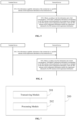
- FIG. 3A is a flowchart of a communication method according to some embodiments of this application. As shown in FIG. 3A , the method according to some embodiments includes a following step.
- the terminal device sends first information to the network device, where the first information includes capability information of the terminal device and SRS antenna switch requirement information of the terminal device.
- the network device receives the first information sent by the terminal device.
- the capability information of the terminal device (UE capabilities) included in the first information is used for indicating the antenna switch capability supported by the terminal device.
- the capability information of the terminal device may include: a capability of whether the terminal device supports SRS antenna switch on combination of frequency bands, and SRS antenna switch modes supported by terminal device.
- the capability information of the terminal device may include: information indicating whether the SRS antenna switch will affect the reception of the terminal device in other frequency bands (e.g., tx Switch Impact To Rx), and information indicating whether the SRS antenna switch will affect the transmission of the terminal device on other frequency bands (e.g., tx Switch With Another Band).
- information indicating whether the SRS antenna switch will affect the reception of the terminal device in other frequency bands e.g., tx Switch Impact To Rx
- information indicating whether the SRS antenna switch will affect the transmission of the terminal device on other frequency bands e.g., tx Switch With Another Band.
- the capability information of the terminal device may further include: information used for indicating a switch delay (delay) supported by the terminal device.
- the information of the switch delay supported by the terminal device may be the information of the switch delay type supported by the terminal device.
- the SRS antenna switch requirement information (SRS antenna port switch requirement information) corresponding to the terminal device includes at least one of the following information: an insertion loss fallback value of a target frequency band corresponding to the SRS antenna switch performed by the terminal device, switch delay requirement and interruption requirement corresponding to the SRS antenna switch performed by the terminal device.
- the insertion loss fallback value is the insertion loss fallback value of the target frequency band corresponding to the SRS antenna switch performed by the terminal device. Specifically, the insertion loss backoff value is used for indicating additional losses of reception power and throughput on the target frequency band corresponding to the SRS antenna switch performed by the terminal device.
- the switch delay requirement is the switch delay requirement corresponding to the SRS antenna switch performed by the terminal device.
- the switch delay requirement may include whether the terminal device supports switch delay, and/or requirements of corresponding switch delay types when the terminal device supports different switches, where each switch delay type corresponds to one or more switch delays.
- the interruption requirement is the interruption requirement corresponding to the SRS antenna switch performed by the terminal device.
- the interruption requirement may include whether the terminal device supports interruption of SRS antenna switch, and/or a requirement for a corresponding interruption time when the terminal device supports interruption of SRS antenna switch.
- the SRS antenna switch requirement information is used to reflect the implementation requirements of the terminal device for performing SRS antenna switch
- the SRS antenna switch requirement information may also be referred to as other names, for example, first requirement information, first SRS antenna switch requirement, SRS antenna switch implementation requirement, and the like, which are not limited in the embodiments of this application.
- the SRS antenna switch requirement information may be configured by the network side, or may be determined by the terminal device itself.
- the capability information of the terminal device and the SRS antenna switch requirement information of the terminal device may be sent separately, or the capability information of the terminal device and the SRS antenna switch requirement information of the terminal device may be sent at the same time, or the SRS antenna switch requirement information of the terminal device may be indicated by the capability information of the terminal device, which is not limited in the embodiments of this application.
- the first information may be sent by the terminal device through multiple signalings, or may be sent by the terminal device through a single signaling, which is not limited in the embodiments of this application.
- the terminal device reports the capability information of the terminal device and the SRS antenna switch requirement information indicating requirement for the terminal device to perform SRS antenna switch, so the network device can accurately obtain the requirement for the terminal device to perform SRS antenna switch, thereby providing a basis for minimizing the impact of communication link adaptation.
- a following step may be further included.
- the network device acquires SRS antenna switch configuration information corresponding to the terminal device according to the first information and a first correspondence, where the SRS antenna switch configuration information meets the requirement indicated by the SRS antenna switch requirement information.
- the purpose of this step is to obtain the SRS antenna switch configuration information, and the SRS antenna switch configuration information meets the requirement indicated by the SRS antenna switch requirement information.
- the first correspondence may be preset, or may be defined in a protocol, or may also be configured by the network side, which is not limited in the embodiments of this application.
- the first correspondence may include multiple correspondences, and the multiple correspondences are all used to obtain the SRS antenna switch configuration information.
- different correspondences may be used to obtain one or more parameters included in different SRS antenna switch configuration information, or used to obtain one or more configuration information, which is not limited in the embodiments of this application.
- the network device accurately acquires SRS antenna switch configuration information that meets the SRS antenna switch requirement based on the first information reported by the terminal device and the first correspondence. In this way, the network device can obtain accurate SRS antenna switch configuration information, thereby providing a basis for minimizing the impact of communication link adaptation.
- FIG. 3B is a flowchart of a communication method according to some other embodiments of this application. Based on the embodiments shown in FIG. 3A , the method in some embodiments may further include a following step after S101.
- the network device sends information indicating an SRS antenna switch mode to the terminal device.
- the network device may need to send information for indicating the SRS antenna switch mode to the terminal device, so as to indicate the terminal device to perform SRS antenna switch according to the SRS antenna switch mode sent by the network device.
- the network device determines that the terminal device is configured with multiple SRS antenna switch modes according to the SRS antenna switch request information of the terminal device, then the network device configures the SRS antenna switch mode for the terminal device from the multiple SRS antenna switch modes, and sends to the terminal device the information indicating the configured SRS antenna switch mode.
- the network device determines, according to the first information, that the terminal device is configured with multiple SRS antenna switch modes, the network device may indicate the terminal device to switch between the configured multiple SRS antenna switch modes in an indicated manner.
- the SRS antenna switch modes acquired by the network device includes switch mode 1 and switch mode 2, then the network device may indicate the terminal device to perform SRS antenna switch according to switch mode 1 in time period 1, and perform SRS antenna switch according to switch mode 2 in time period 2.
- the terminal device may determine the SRS antenna switch mode of the terminal device according to the SRS antenna switch requirement information.
- the terminal device determines the SRS antenna switch mode of the terminal device according to the capability information of the terminal device and the SRS antenna switch requirement information of the terminal device included in the first information.
- the determined SRS antenna switch mode of the terminal device may include one SRS antenna switch mode, and may also include multiple SRS antenna switch modes, which are not limited in the embodiments of this application.
- the network device sends information for indicating the SRS antenna switch mode to the terminal device
- the terminal device can obtain the SRS antenna switch configuration information of the terminal device according to the SRS antenna switch mode indicated by the network device and the capability information of the terminal device, and perform the SRS antenna switch according to the determined SRS antenna switch configuration, thereby improving the flexibility of RRM of the terminal device for the SRS antenna switch, and facilitating to improve the efficiency of the communication system.
- a following step may be further included after S 103.
- the terminal device acquires SRS antenna switch configuration information according to the capability information of the terminal device, the SRS antenna switch mode indicated by the network device, and the first correspondence.
- the terminal device may obtain the SRS antenna switch configuration information that meets the requirement indicated by the SRS antenna switch requirement information according to the capability information of the terminal device, the SRS antenna switch mode indicated by the network device, and the first correspondence.
- the network device indicates the SRS antenna switch mode to the terminal device, and the terminal device obtains the SRS antenna switch configuration information that meets the requirement indicated by the SRS antenna switch requirement information according to the SRS antenna switch mode indicated by the network device. In this way, the network device and the terminal device can obtain the SRS antenna switch configuration information, the signaling overhead of transmitting the SRS antenna switch configuration is reduced, and the efficiency of the communication system is improved.
- a following step may be further included after S104.
- the network device performs downlink scheduling according to the SRS antenna switch configuration information.
- the network device can reasonably schedule the terminal device according to the SRS antenna switch configuration information corresponding to the terminal device to avoid conflict of transmission resources, thereby improving the transmission performance of the terminal device and improving the efficiency of the communication system.
- FIG. 3C is a flowchart of a communication method according to some other embodiments of this application.
- the method shown in some embodiments, on the basis of the embodiments shown in FIG. 3A , may further include a following step after S102.
- the network device sends the SRS antenna switch configuration information to the terminal device.
- the terminal device receives the SRS antenna switch configuration information sent by the network device.
- the network device can configure the SRS antenna switch configuration information of the terminal device. Therefore, after acquiring the SRS antenna switch configuration information, the network device may also send the SRS antenna switch configuration information to the terminal device.
- the network device sends the SRS antenna switch configuration information and the information indicating the SRS antenna switch mode to the terminal device
- the SRS antenna switch configuration information and the information indicating the SRS antenna switch mode may be sent through the same signaling or through different signalings, which is not limited in the embodiments of this application.
- the network device indicates the SRS antenna switch configuration information to the terminal device, and the terminal device performs SRS antenna switch according to the SRS antenna switch configuration information configured by the network device. In this way, network device and terminal device obtain the SRS antenna switch configuration, thereby providing a basis for the network device to perform reasonable downlink scheduling.
- a following step may be further included after S103'.
- the network device performs downlink scheduling according to the SRS antenna switch configuration information.
- the network device can reasonably schedule the terminal device according to the SRS antenna switch configuration information corresponding to the terminal device to avoid conflict of transmission resources, thereby improving the transmission performance of the terminal device and improving the efficiency of the communication system.
- the SRS antenna switch configuration information obtained by the network device which includes the insertion loss fallback value of the target frequency band corresponding to the SRS antenna switch performed by the terminal device, the switch delay configuration information and the interruption configuration information, respectively.
- FIG. 4 is a flowchart of a communication method according to some other embodiments of this application.
- the SRS antenna switch configuration information obtained by the network device includes the insertion loss fallback value of the target frequency band corresponding to the SRS antenna switch performed by the terminal device (abbreviated as the insertion loss fallback value).
- the method according to some embodiments includes following steps.
- the terminal device sends first information to the network device, where the first information includes capability information of the terminal device and SRS antenna switch requirement information of the terminal device.
- Step S201 in some embodiments is similar to step S 101 in the embodiments shown in FIG. 3A , and reference may be made to the detailed description in the embodiments shown in FIG. 3A , which is not repeated here.
- the network device obtains, according to the first information and a second correspondence, the insertion loss fallback value of the target frequency band corresponding to the SRS antenna switch performed by the terminal device, which is included in the SRS antenna switch configuration information.
- the first correspondence described in the embodiments shown in FIG. 3 includes the second correspondence in the embodiments described herein.
- the second correspondence is a correspondence among multiple SRS antenna switch modes, frequency bands corresponding to the SRS antenna switch performed by the terminal device, and insertion loss fallback values of the frequency bands.
- the insertion loss fallback values corresponding to different frequency bands are not exactly the same.
- the insertion loss fallback values corresponding at least two frequency bands in the same SRS antenna switch mode may be the same.
- the configurable insertion loss fallback values in different frequency bands may be consistent with the insertion loss fallback corresponding to the radio frequency indicators of the terminal device in RAN4 protocol.
- the insertion loss fallback values corresponding to different frequency bands are elements in the same sequence.
- the insertion loss fallback values of N frequency bands correspond to the elements in the sequence ⁇ a1, a2, ..., aN ⁇ , respectively, where N is a positive integer.
- different frequency bands correspond to different insertion loss fallback values in the same SRS antenna switch mode.
- all SRS antenna switch modes correspond to a set of insertion loss fallback value sequences, which are applicable to all frequency bands.
- different frequency bands in the same SRS antenna switch mode may correspond to the same insertion loss backoff value.
- the second correspondence may be preset, or may be defined in a protocol, or may also be configured by the network side, which is not limited in the embodiments of this application.
- the insertion loss fallback value of the target frequency band corresponding to the SRS antenna switch performed by the terminal device included in the SRS antenna switch configuration information meets the requirement on insertion loss fallback value indicated in the SRS antenna switch requirement information of the terminal device.
- the terminal device reports the first information, and the network device accurately obtains, based on the first information and the second correspondence reported by the terminal device, the insertion loss fallback value of the target frequency band corresponding to SRS antenna switch performed by the terminal device included in the SRS antenna switch configuration information. In this way, the network device can obtain the accurate insertion loss fallback value of the target frequency band corresponding to the SRS antenna switch, which is beneficial to the accurate calculation of the receiver sensitivity of the terminal device.
- FIG. 5 is a flowchart of a communication method according to some other embodiments of this application.
- description is given in detail where the SRS antenna switch configuration information obtained by the network device includes the switch delay configuration information.
- the method according to some embodiments includes following steps.
- the terminal device sends first information to the network device, where the first information includes capability information of the terminal device and SRS antenna switch requirement information of the terminal device.
- Step S301 in some embodiments is similar to step S101 in the embodiments shown in FIG. 3A , and reference may be made to the detailed description in the embodiments shown in FIG. 3A , which is not repeated here.
- the network device acquires, according to the first information and a third correspondence, the switch delay configuration information corresponding to SRS antenna switch performed by the terminal device, which is included in the SRS antenna switch configuration information.
- the first correspondence described in the embodiments shown in FIG. 3 includes the third correspondence in the embodiments described herein, and the third correspondence is a correspondence among the capability information of various terminal devices, various SRS antenna switch modes, and the switch delay configuration information.
- the switch delay configuration information may include whether the terminal device supports switch delay, that is, the capabilities of different terminal devices correspond to support or not-support of switch delay when the SRS antenna switch is supported.
- the switch delay configuration information further includes corresponding switch delay types when the terminal device supports different switch delays, where each switch delay type corresponds to one or more switch delays.
- the switch delay configuration information may also include: whether the terminal device supports switch delay, and the switch delay types corresponding to different switch delays supported by the terminal device.
- the terminal device supports the switch delay, and/or, the requirement on the switch delay type when the terminal device supports the switch delay.
- different switch types correspond to one or more switch delays. Therefore, the requirement on the switch delay type is the requirement of the switch delay corresponding to the terminal device.
- the third correspondence is a correspondence between the capability information of various terminal devices, various SRS antenna switch modes, and whether the terminal device supports switch delay. In this way, it can be determined whether the terminal device supports switch delay according to the first information reported by the terminal device and the third correspondence.
- the network device may determine the switch delay corresponding to the SRS antenna switch performed by the terminal device according to a preset switch delay.
- all terminal devices support switch delay
- multiple switch delay types may be defined, and each switch delay type corresponds to one or more switch delays.
- the third correspondence may be a correspondence between the capability information of various terminal devices, various SRS antenna switch modes, and switch delay types, then the network device may determine the switch delay type corresponding to the SRS antenna switch performed by the terminal device according to the first information reported by the terminal device and the third correspondence, and further determine the switch delay according to the switch delay type corresponding to the SRS antenna switch performed by the terminal device.
- the switch delay types may include switch delay type 1 (type1) and switch delay type 2 (type2), where the switch delay type 1 may correspond to 7 SRS antenna switch modes in the current version of Rel-15 protocol, and the switch delay type 2 corresponds to the 6 SRS antenna switch modes newly added in the current version of Rel-16 protocol.
- the switch delay type 1 may correspond to a switch delay, which may be preconfigured by the protocol.
- the switch delay type 2 may correspond to multiple switch delays or multiple groups of switch delays. For example, when a bandwidth part (BWP) switch is supported by multiple carriers, the switch delay may vary according to the capabilities of the terminal device.
- BWP bandwidth part
- the multiple switch delays included in each group of switch delays may correspond to different interruptions.
- a group of switch delays is expressed as ⁇ 0, 35, 140, 210 ⁇ , then the four switch delays included in this group may respectively correspond to four groups of interruptions of SRS antenna switch.
- the switch delay types may also include more than two switch delay types.
- each switch delay type corresponds to one or more SRS antenna switch modes.
- the switch delays of all configurable SRS antenna switch modes may be grouped, with each group corresponding to a different switch delay type.
- the correspondence may be implemented by means of network signaling configuration or protocol pre-configuration.
- the SRS antenna switch mode may also correspond to the switch delay, that is, one SRS antenna switch mode corresponds to one switch delay.
- the switch delays corresponding to different SRS antenna switch modes may be the same or different, which is not limited in the embodiments of this application.
- the configurable switch delays of each SRS antenna switch mode may be consistent with the BWP switch delay of the terminal device in the RAN4 protocol.
- the third correspondence may be preset, or may be defined in a protocol, or may also be configured by the network side, which is not limited in the embodiments of this application.
- the obtained SRS antenna switch configuration information includes the switch delay configuration information corresponding to SRS antenna switch performed by the terminal device, which meets the switch delay requirement indicated in the SRS antenna switch requirement information of the terminal device.
- the terminal device reports the first information
- the network device accurately obtains, based on the first information reported by the terminal device and the third correspondence, the switch delay configuration information included in the SRS antenna switch configuration information corresponding to the SRS antenna switch performed by the terminal device.
- the network device can obtain the accurate switch start time and time length corresponding to the SRS antenna switch, which is beneficial to minimize the impact on the transmission performance and link adaptation of the terminal device, thereby improving the efficiency of the communication system.
- FIG. 6 is a flowchart of a communication method according to some other embodiments of this application. In these embodiments, description is given in detail where the SRS antenna switch configuration information acquired by the network device includes the interruption configuration information. As shown in FIG. 6 , the method according to some embodiments includes following steps.
- the terminal device sends first information to the network device, where the first information includes capability information of the terminal device and SRS antenna switch requirement information of the terminal device.
- Step S401 in some embodiments is similar to step S101 in the embodiments shown in FIG. 3A , and reference may be made to the detailed description in the embodiments shown in FIG. 3A , which is not repeated here.
- the network device acquires, according to the first information and a fourth correspondence, the interruption configuration information corresponding to SRS antenna switch performed by the terminal device, which is included in the SRS antenna switch configuration information.
- the first correspondence described in the embodiments shown in FIG. 3 includes the four correspondences in the embodiments described herein, where the four correspondences is a correspondence among the capability information of various terminal devices, the various SRS antenna switch modes, and the interrupt configuration information.
- the interruption configuration information may include: whether the terminal device supports interruption of SRS antenna switch, and/or a corresponding interruption time when the terminal device supports the interruption of SRS antenna switch.
- the terminal device can be determined whether the terminal device supports the interruption of SRS antenna switch, and/or the corresponding interruption time when the terminal device supports the interruption of SRS antenna switch.
- the interruption times corresponding to the interruption of SRS antenna switch supported by all terminal devices are the same. Then, regardless of whether the capabilities of the terminal devices are different, the interruption times corresponding to the interruption of SRS antenna switch performed by the terminal devices are the same.
- the same interruption time set corresponds to the interruption of SRS antenna switch supported by terminal devices of different switch delay types, where the interruption time set includes at least one interruption time. That is to say, in the fourth correspondence, for the same SRS antenna switch mode, terminal devices of different switch delay types correspond to the same one interruption time or the same group of interruption times.
- the switch delay type may refer to the description in the embodiments shown in FIG. 5 , or may be determined according to the third correspondence in the embodiments shown in FIG. 5 .
- the interruption time set includes multiple interruption times, there may be no correlation between the interruption time and the SRS antenna switch mode.
- any interruption time in the interruption time set may be configured.
- association relationship may be present between the interruption time and the SRS antenna switch mode.
- the interruption times corresponding to all SRS antenna switch modes configurable by the terminal device are grouped, with respective groups corresponding to different interruption times.
- This association relationship may be implemented by means of network signaling configuration or protocol pre-configuration.
- the SRS antenna switch modes are expressed as a set ⁇ A1, A2, ..., An, B1, B2, ..., Bn, C1, C2, ..., Cn ⁇ ;
- the switch delay types include switch delay type A, switch delay type B, and switch delay type C; and a set of interruption times is ⁇ iA1, iA2, ..., iAn, iB1, iB2, ..., iBn, iC1, iC2, ..., iCn ⁇ .
- the terminal device that supports the SRS antenna switch mode ⁇ A1, A2, ..., An ⁇ corresponds to the switch delay type A, and the corresponding interruption time is ⁇ iA1, iA2, ..., iAn ⁇ ;
- the terminal device that supports the SRS antenna switch mode ⁇ B 1, B2, ..., Bn ⁇ corresponds to the switch delay type B, and the corresponding interruption time is ⁇ iB1, iB2, ..., iBn ⁇ ;
- the terminal device that supports SRS antenna switch mode ⁇ C1, C2, ..., Cn ⁇ corresponds to the switch delay type C, and the corresponding interruption time is ⁇ iC1, iC2, ..., iCn ⁇ ; where n may be a positive integer.
- the switch delay supported by the SRS antenna switch mode there is a one-to-one correspondence between the switch delay supported by the SRS antenna switch mode and the interruption time.
- SRS antenna switch mode 1 supports switch delay 1, and the switch delay 1 corresponds to interruption time 1;
- SRS antenna switch mode 2 supports switch delay 2, and the switch delay 2 corresponds to interruption time 2;
- SRS antenna switch mode 3 supports switch delay 3, and the switch delay 3 corresponds to interruption time 3; and so on.
- the interruption times corresponding to the switch delays supported by different SRS antenna switch modes may be the same or different, which is not limited in the embodiments of this application.
- the interruption time 1 corresponding to the switch delay 1 supported by the SRS antenna switch mode 1 and the interruption time 2 corresponding to the switch delay 2 supported by the SRS antenna switch mode 2 may be the same or different.
- the correspondence between the switch delay supported by the SRS switch mode and the interruption time may be configured by network signaling or preconfigured in a protocol.
- the interruption times corresponding to the switch delays supported by the SRS antenna switch modes may be consistent with the interruption times corresponding to the BWP switch in the RAN4 protocol.
- the fourth correspondence may be preset, or may also be defined in a protocol, or may also be configured by the network side, which is not limited in the embodiments of this application.
- the interruption configuration information corresponding to SRS antenna switch performed by the terminal device included in the obtained SRS antenna switch configuration information meets the interruption requirement indicated in the SRS antenna switch requirement information of the terminal device.
- the terminal device reports the first information
- the network device accurately obtains, based on the first information reported by the terminal device and the fourth correspondence, the interruption configuration information corresponding to the SRS antenna switch performed by the terminal device, which is included in the SRS antenna switch configuration information.
- the network device can obtain the accurate interruption start time and time length of the SRS antenna switch, which is beneficial to minimize the impact on the transmission performance and link adaptation of the terminal device, thereby improving the efficiency of the communication system.
- the above embodiments may be implemented alone or in combination.
- the SRS antenna switch configuration information includes two or more of the insertion loss fallback value of the target frequency band corresponding to the SRS antenna switch of the terminal device, the switch delay configuration information and interruption configuration information corresponding to the SRS antenna switch performed by the terminal device, the embodiments shown in FIG. 4 to FIG. 6 may be implemented in combination.
- the terminal device may also determine the SRS antenna switch configuration information corresponding to the SRS antenna switch performed by the terminal device according to the capability information thereof, the SRS antenna switch mode indicated by the network device, and the first correspondence, where the SRS antenna switch configuration information includes at least one of the following information: the insertion loss fallback value of the target frequency band corresponding to the SRS antenna switch of the terminal device, the switch delay configuration information and the interruption configuration information corresponding to the SRS antenna switch performed by the terminal device.
- the specific implementation method of the terminal device to obtain the SRS antenna switch configuration information according to the capability information thereof, the SRS antenna switch mode indicated by the network device, and the first correspondence, is similar to the method of the network device, except that the execution body is different, so the reference may be made to the detailed description of the network device acquiring the SRS antenna switch configuration information corresponding to the terminal device, which will not be repeated here.
- FIG. 7 is a block diagram of a network device according to some embodiments of this application.
- the communication device 200 provided in some embodiments includes a transceiving module 201.
- the transceiving module 201 is configured to receive first information sent by a terminal device, where the first information includes capability information of the terminal device and SRS antenna switch requirement information of the terminal device.
- the capability information of the terminal device is used for indicating antenna switch capability supported by the terminal device; and the SRS antenna switch requirement information is used for indicating requirement for the terminal device to perform SRS antenna switch.
- the SRS antenna switch requirement information includes at least one of following information: an insertion loss fallback value of a target frequency band corresponding to the SRS antenna switch performed by the terminal device, switch delay requirement and interruption requirement corresponding to the SRS antenna switch performed by the terminal device.
- the communication device 200 further includes a processing module 202.
- the processing module 202 is configured to obtain SRS antenna switch configuration information of the terminal device according to the first information and a first correspondence, where the first correspondence is a correspondence between the SRS antenna switch configuration information and capability information of various terminal devices.
- the first correspondence includes a second correspondence, where the second correspondence is a correspondence between multiple SRS antenna switch modes, a frequency band corresponding to the SRS antenna switch performed by the terminal device, and an insertion loss fallback value of the frequency band.
- insertion loss fallback values corresponding to different frequency bands are not exactly the same.
- the insertion loss fallback values corresponding to different frequency bands are elements in a same sequence.
- the capability information of the terminal device further includes information used for indicating a switch delay type supported by the terminal device.
- the first correspondence includes a third correspondence, where the third correspondence is a correspondence between capability information of various terminal devices, an SRS antenna switch mode, and the switch delay configuration information.
- the switch delay configuration information includes whether the terminal device supports a switch delay.
- the switch delay configuration information includes switch delay types corresponding to different switch delays supported by the terminal device, where each of the switch delay types corresponds to one or more switch delays.
- the first correspondence includes a fourth correspondence, where the fourth correspondence is a correspondence between capability information of various terminal devices, various SRS antenna switch modes, and the interruption configuration information.
- the interruption configuration information includes whether the terminal device supports interruption of the SRS antenna switch.
- the interruption configuration information includes a corresponding interruption time when the terminal device supports the interruption.
- a corresponding interruption time set when terminal devices of different switch delay types support the interruption is the same, and the interruption time set includes at least one interruption time.
- switch delays supported by the SRS antenna switch modes are in one-to-one correspondence with interruption times.
- the interruption times corresponding to different switch delays are not exactly the same.
- the processing module 202 is further configured to determine an SRS antenna switch mode of the terminal device according to the SRS antenna switch requirement information.
- the transceiving module 201 is further configured to send information indicating the SRS antenna switch mode to the terminal device.
- the processing module 202 is further configured to determine the SRS antenna switch configuration information according to the determined SRS antenna switch mode.
- the transceiving module 201 is further configured to send information indicating the SRS antenna switch configuration information to the terminal device.
- the processing module 202 is further configured to perform downlink scheduling according to the SRS antenna switch configuration information of the terminal device.
- the communication device can be configured to implement the technical solutions performed by the network device in the above method embodiments, and the implementation principles and technical effects thereof are similar. So reference can be made to the detailed description of the above method embodiments, which will not be repeated here.
- FIG. 8 is a block diagram of a communication device according to some other embodiments of this application.
- the communication device 300 provided in some embodiments includes a transceiver module 301 configured to send first information to a network device, where the first information includes capability information of the terminal device and SRS antenna switch requirement information of the terminal device.
- the capability information of the terminal device is used for indicating antenna switch capability supported by the terminal device; and the SRS antenna switch requirement information is used for indicating requirement for the terminal device to perform SRS antenna switch.
- the SRS antenna switch requirement information includes at least one of following information: an insertion loss fallback value of a target frequency band corresponding to the SRS antenna switch of the terminal device, switch delay requirement and interruption requirement corresponding to the SRS antenna switch performed by the terminal device.
- the communication device 300 further includes a processing module 302.
- the processing module 302 is configured to obtain SRS antenna switch configuration information of the terminal device, where the SRS antenna switch configuration information meets the requirement indicated by the SRS antenna switch requirement information.
- the transceiving module 301 is further configured to receive information indicating an SRS antenna switch mode sent by the network device.
- the processing module 302 is specifically configured to obtain the SRS antenna switch configuration information of the terminal device according to the capability information of the terminal device, an SRS antenna switch mode indicated by the network device, and a first correspondence.
- the first correspondence is a correspondence between the SRS antenna switch configuration information and capability information of various terminal devices.
- the first correspondence includes a second correspondence, where the second correspondence is a correspondence between multiple SRS antenna switch modes, a frequency band corresponding to the SRS antenna switch performed by the terminal device, and an insertion loss fallback value of the frequency band.
- insertion loss fallback values corresponding to different frequency bands are not exactly the same.
- the insertion loss fallback values corresponding to different frequency bands are elements in a same sequence.
- the capability information of the terminal device further includes information used for indicating a switch delay type supported by the terminal device.
- the first correspondence includes a third correspondence, where the third correspondence is a correspondence between capability information of various terminal devices, multiple SRS antenna switch modes, and the switch delay configuration information.
- the switch delay configuration information includes whether the terminal device supports a switch delay.
- the switch delay configuration information includes switch delay types corresponding to different switch delays supported by the terminal device, where each of the switch delay types corresponds to one or more switch delays.
- the first correspondence includes a fourth correspondence, where the fourth correspondence is a correspondence between capability information of various terminal devices, the SRS antenna switch modes, and the interruption configuration information.
- the interruption configuration information includes whether the terminal device supports interruption of the SRS antenna switch.
- the interruption configuration information includes a corresponding interruption time when the terminal device supports the interruption.
- a corresponding interruption time set when terminal devices of different switch delay types support the interruption is the same, and the interruption time set includes at least one interruption time.
- switch delays supported by the SRS antenna switch modes are in one-to-one correspondence with interruption times.
- the interruption times corresponding to different switch delays are not exactly the same.
- the transceiving module 301 is further configured to receive the SRS antenna switch configuration information sent by the network device.
- the processing module 302 obtains, according to the capability information of the terminal device and/or the SRS antenna switch mode supported by the terminal device and the first correspondence, the SRS antenna switch configuration information in a similar manner as the network device, while the difference only lies in the execution subject. So reference can be made to the detailed description of acquiring the SRS antenna switch requirement information corresponding to the terminal device by the network device, which will not be repeated here.
- the communication device can be configured to implement the technical solutions performed by the terminal device in the above method embodiments, and the implementation principles and technical effects thereof are similar, which will not be repeated here.
- FIG. 9 is a block diagram of a communication device according to some other embodiments of this application.
- the communication device 400 provided in some embodiments includes: a memory 411, a processor 412, and an interface 413 for communicating with the terminal device.
- the memory 411 stores computer-executed instructions.
- the processor 412 executes the computer-executed instructions stored in the memory 411, causing the processor 412 to implement the technical solution of the network device in any of the foregoing method embodiments.
- the memory and the processor may be connected through a system bus 414.
- FIG. 9 may be a simple design of the network device. Embodiments of this application do not limit the number of processors and memories in the network device. FIG. 9 only uses one (processor and memory) as an example for description.
- FIG. 10 is a block diagram of a communication device according to some other embodiments of this application.
- the communication device 500 provided in some embodiments includes: a memory 511, a processor 512, and an interface 513 for communicating with terminal device.
- the memory 511 stores computer-executed instructions
- the processor 512 executes the computer-executed instructions stored in the memory 511, causing the processor 512 to implement the technical solution of the terminal device in any of the foregoing method embodiments.
- the memory and the processor may be connected through a system bus 514.
- FIG. 10 may be a simple design of the terminal device. Embodiments of this application do not limit the number of processors and memories in the network device. FIG. 10 only uses one (processor and memory) as an example for description.
- the memory, the processor, and the interface may be connected through a bus.
- the memory may be integrated inside the processor.
- Embodiments of this application further provide a computer-readable storage medium, where computer-executable instructions are stored in the computer-readable storage medium, and the computer-executable instructions, when being executed by a processor, are used for implementing the technical solution of the network device according to any of the foregoing method embodiments.
- Embodiments of this application further provide a computer-readable storage medium, where computer-executable instructions are stored in the computer-readable storage medium, and the computer-executable instructions, when being executed by a processor, are used for implementing the technical solution of the terminal device according to any of the foregoing method embodiments.
- Embodiments of this application further provide a program, which, when the being executed by a processor, is used for performing the technical solution of the network device according to any of the foregoing method embodiments.
- the above-mentioned processor may be a chip.
- Embodiments of this application further provide a program, which, when the being executed by a processor, is used for performing the technical solution of the terminal device according to any of the foregoing method embodiments.
- the above-mentioned processor may be a chip.
- Embodiments of this application further provide a computer program product, including program instructions, where the program instructions are used for implementing the technical solution of the network device according to any of the foregoing method embodiments.
- Embodiments of this application further provide a computer program product, including program instructions, where the program instructions are used for implementing the technical solution of the terminal device according to any of the foregoing method embodiments.
- Embodiments of this application further provide a chip, including: a processing module and a communication interface, where the processing module is configured to perform the technical solution at the network device side according to any of the foregoing method embodiments.
- the chip also includes a storage module (e.g., a memory), where the storage module is used for storing instructions, the processing module is used for executing the instructions stored in the storage module, and the execution of the instructions stored in the storage module causes the processing module to perform the technical solution of the network device according to any of the foregoing method embodiments.
- a storage module e.g., a memory
- Embodiments of this application further provide a chip, including: a processing module and a communication interface, where the processing module is configured to perform the technical solution at the terminal device side according to any of the foregoing method embodiments.
- the chip also includes a storage module (e.g., a memory), where the storage module is used for storing instructions, the processing module is used for executing the instructions stored in the storage module, and the execution of the instructions stored in the storage module causes the processing module to perform the technical solution of the terminal device according to any of the foregoing method embodiments.
- a storage module e.g., a memory
- the disclosed apparatus and method may be implemented in other manners.
- the device embodiments described above are only illustrative.
- the division of the modules is only a logical function division. In actual implementation, there may be other division manners.
- multiple modules may be combined or integrated to another system, or some features may be ignored or not implemented.
- the mutual coupling or direct coupling or communication connection shown or discussed may be through some interfaces, and the indirect coupling or communication connection of modules may be in electrical, mechanical or other forms.
- the processor may be a central processing unit (abbreviated as CPU), or other general-purpose processors, digital signal processors (abbreviated as DSPs), application specific integrated circuit (abbreviated as ASIC) and so on.
- a general purpose processor may be a microprocessor or the processor may be any conventional processor or the like. The steps in combination with the method disclosed in this application may be directly embodied as being executed by a hardware processor, or executed by a combination of hardware and software modules in the processor.
- ROM read-only memory
- RAM random access memory
- flash memory hard disk
- solid state drive magnetic tape
- floppy disk optical disc
Landscapes
- Engineering & Computer Science (AREA)
- Signal Processing (AREA)
- Computer Networks & Wireless Communication (AREA)
- Computer Security & Cryptography (AREA)
- Databases & Information Systems (AREA)
- Mobile Radio Communication Systems (AREA)
Applications Claiming Priority (1)
| Application Number | Priority Date | Filing Date | Title |
|---|---|---|---|
| PCT/CN2020/099049 WO2022000214A1 (fr) | 2020-06-29 | 2020-06-29 | Procédé et appareil de communication, et support de stockage lisible |
Publications (2)
| Publication Number | Publication Date |
|---|---|
| EP4175380A1 true EP4175380A1 (fr) | 2023-05-03 |
| EP4175380A4 EP4175380A4 (fr) | 2023-08-02 |
Family
ID=79315013
Family Applications (1)
| Application Number | Title | Priority Date | Filing Date |
|---|---|---|---|
| EP20943086.7A Pending EP4175380A4 (fr) | 2020-06-29 | 2020-06-29 | Procédé et appareil de communication, et support de stockage lisible |
Country Status (4)
| Country | Link |
|---|---|
| US (1) | US12176978B2 (fr) |
| EP (1) | EP4175380A4 (fr) |
| CN (1) | CN115669125A (fr) |
| WO (1) | WO2022000214A1 (fr) |
Families Citing this family (3)
| Publication number | Priority date | Publication date | Assignee | Title |
|---|---|---|---|---|
| CN115669125A (zh) | 2020-06-29 | 2023-01-31 | Oppo广东移动通信有限公司 | 通信方法、装置及可读存储介质 |
| CN114598371B (zh) * | 2022-05-10 | 2022-09-09 | 荣耀终端有限公司 | 获取天线组合的方法、电子设备和计算机可读存储介质 |
| WO2024098303A1 (fr) * | 2022-11-09 | 2024-05-16 | 北京小米移动软件有限公司 | Procédé et appareil de transmission d'informations sur les capacités, et support de stockage lisible |
Family Cites Families (16)
| Publication number | Priority date | Publication date | Assignee | Title |
|---|---|---|---|---|
| RU2724320C1 (ru) * | 2016-11-02 | 2020-06-22 | Телефонактиеболагет Лм Эрикссон (Пабл) | Управление воздействием переключения srs на передачи по каналу восходящей линии связи |
| WO2019037026A1 (fr) * | 2017-08-24 | 2019-02-28 | Qualcomm Incorporated | Procédé destiné à l'émission de signal de référence de sondage servant à un équipement utilisateur comportant une émission/réception asymétrique |
| CN109803253B (zh) * | 2017-11-17 | 2020-06-23 | 维沃移动通信有限公司 | 一种信号传输方法、终端及网络设备 |
| US10863494B2 (en) * | 2018-01-22 | 2020-12-08 | Apple Inc. | Control signaling for uplink multiple input multiple output, channel state information reference signal configuration and sounding reference signal configuration |
| US10938529B2 (en) * | 2018-02-14 | 2021-03-02 | Qualcomm Incorporated | Sounding reference signal antenna switching in scheduled entities having at least four antennas |
| US12003974B2 (en) * | 2018-07-30 | 2024-06-04 | Qualcomm Incorporated | Carrier switching and antenna switching for long term evolution and new radio dual connectivity |
| WO2020034128A1 (fr) * | 2018-08-15 | 2020-02-20 | Oppo广东移动通信有限公司 | Procédé de communication sans fil, et procédé et dispositif d'émission de signal de liaison montante pour dispositif terminal |
| US12075455B2 (en) * | 2019-03-28 | 2024-08-27 | Lg Electronics Inc. | Method for transmitting and receiving sounding reference signal in wireless communication system, and apparatus therefor |
| WO2020197357A1 (fr) * | 2019-03-28 | 2020-10-01 | 엘지전자 주식회사 | Procédé d'émission et de réception de signal de référence de sondage dans un système de communications sans fil, et dispositif correspondant |
| US11509372B2 (en) * | 2019-05-03 | 2022-11-22 | Qualcomm Incorporated | Capability information for sounding reference signal improvements |
| CN110519853B (zh) * | 2019-09-06 | 2023-04-28 | 中兴通讯股份有限公司 | 切换指示方法、切换方法、装置、服务节点、终端及介质 |
| US11632754B2 (en) * | 2020-02-06 | 2023-04-18 | Qualcomm Incorporated | Support of multiple SRS in the same subframe |
| US12302256B2 (en) * | 2020-02-11 | 2025-05-13 | Lg Electronics Inc. | Method for transmitting and receiving signal in wireless communication system, and apparatus supporting same |
| EP4104353A4 (fr) * | 2020-02-14 | 2023-11-01 | Lenovo (Beijing) Limited | Signaux de référence de sondage pour commutation d'antenne |
| CN115669125A (zh) | 2020-06-29 | 2023-01-31 | Oppo广东移动通信有限公司 | 通信方法、装置及可读存储介质 |
| US12041012B2 (en) * | 2020-08-18 | 2024-07-16 | Qualcomm Incorporated | Switching configuration for simultaneous intra and inter-band SRS transmissions |
-
2020
- 2020-06-29 CN CN202080101046.6A patent/CN115669125A/zh active Pending
- 2020-06-29 WO PCT/CN2020/099049 patent/WO2022000214A1/fr not_active Ceased
- 2020-06-29 EP EP20943086.7A patent/EP4175380A4/fr active Pending
-
2022
- 2022-12-27 US US18/089,294 patent/US12176978B2/en active Active
Also Published As
| Publication number | Publication date |
|---|---|
| WO2022000214A1 (fr) | 2022-01-06 |
| CN115669125A (zh) | 2023-01-31 |
| US12176978B2 (en) | 2024-12-24 |
| EP4175380A4 (fr) | 2023-08-02 |
| US20230239017A1 (en) | 2023-07-27 |
Similar Documents
| Publication | Publication Date | Title |
|---|---|---|
| EP4184995B1 (fr) | Procédé de communication sans fil, dispositif terminal et dispositif de réseau | |
| EP2856806B1 (fr) | Procédé, système et appareil pour une communication d'un réseau local sans fil (wlan) en conjonction avec une communication cellulaire | |
| CN111345007B (zh) | 信令指示和接收方法、装置及通信系统 | |
| US12176978B2 (en) | Communication method and apparatus, and readable storage medium | |
| CN109196915B (zh) | 频带处理方法及装置 | |
| CN113170339A (zh) | 一种测量间隔配置方法及装置、终端、网络设备 | |
| JP7526238B2 (ja) | 通信方法、端末装置及びネットワーク装置 | |
| CN114631347A (zh) | 一种小区配置方法及装置、终端设备、网络设备 | |
| EP3809760B1 (fr) | Procédé de communication radio, dispositif de réseau, et dispositif terminal | |
| US12356346B2 (en) | Wireless communication method, terminal device and network device | |
| CN113286276B (zh) | 侧行链路中确定传输模式的方法、终端设备和网络设备 | |
| CN113329426A (zh) | 一种控制测量的方法及装置、终端、网络设备 | |
| WO2023005811A1 (fr) | Procédé de communication et appareil associé | |
| WO2020043009A1 (fr) | Procédé et appareil d'affichage d'iu, et équipement terminal et support d'enregistrement | |
| US20200374887A1 (en) | Channel transmission method and apparatus, and computer storage medium | |
| US12267840B2 (en) | Information transmission method, apparatus, device and storage medium | |
| WO2021179183A1 (fr) | Procédé, appareil et dispositif de transmission d'informations | |
| US11956668B2 (en) | Duplicated data-based transmission method and related devices | |
| CN114040508A (zh) | 通信方法和装置 | |
| CN119697689A (zh) | 无线通信方法、用户设备和网络设备 | |
| EP4709023A1 (fr) | Liaison croisée radio unique améliorée à liaisons multiples et gestion et évitement de collision de trame de commande initiale de même liaison | |
| KR20250134191A (ko) | 빔 관리 방법 및 통신 장치 |
Legal Events
| Date | Code | Title | Description |
|---|---|---|---|
| STAA | Information on the status of an ep patent application or granted ep patent |
Free format text: STATUS: THE INTERNATIONAL PUBLICATION HAS BEEN MADE |
|
| PUAI | Public reference made under article 153(3) epc to a published international application that has entered the european phase |
Free format text: ORIGINAL CODE: 0009012 |
|
| STAA | Information on the status of an ep patent application or granted ep patent |
Free format text: STATUS: REQUEST FOR EXAMINATION WAS MADE |
|
| 17P | Request for examination filed |
Effective date: 20230130 |
|
| AK | Designated contracting states |
Kind code of ref document: A1 Designated state(s): AL AT BE BG CH CY CZ DE DK EE ES FI FR GB GR HR HU IE IS IT LI LT LU LV MC MK MT NL NO PL PT RO RS SE SI SK SM TR |
|
| A4 | Supplementary search report drawn up and despatched |
Effective date: 20230629 |
|
| RIC1 | Information provided on ipc code assigned before grant |
Ipc: H04B 7/06 20060101ALI20230623BHEP Ipc: H04B 7/08 20060101ALI20230623BHEP Ipc: H04W 72/04 20230101AFI20230623BHEP |
|
| DAV | Request for validation of the european patent (deleted) | ||
| DAX | Request for extension of the european patent (deleted) | ||
| STAA | Information on the status of an ep patent application or granted ep patent |
Free format text: STATUS: EXAMINATION IS IN PROGRESS |
|
| 17Q | First examination report despatched |
Effective date: 20251028 |