EP4175459B1 - Methods and systems for determining the growth stage of a plant - Google Patents
Methods and systems for determining the growth stage of a plant Download PDFInfo
- Publication number
- EP4175459B1 EP4175459B1 EP21733964.7A EP21733964A EP4175459B1 EP 4175459 B1 EP4175459 B1 EP 4175459B1 EP 21733964 A EP21733964 A EP 21733964A EP 4175459 B1 EP4175459 B1 EP 4175459B1
- Authority
- EP
- European Patent Office
- Prior art keywords
- plant
- light
- response light
- response
- polarization
- Prior art date
- Legal status (The legal status is an assumption and is not a legal conclusion. Google has not performed a legal analysis and makes no representation as to the accuracy of the status listed.)
- Active
Links
Images


Classifications
-
- G—PHYSICS
- G01—MEASURING; TESTING
- G01N—INVESTIGATING OR ANALYSING MATERIALS BY DETERMINING THEIR CHEMICAL OR PHYSICAL PROPERTIES
- G01N21/00—Investigating or analysing materials by the use of optical means, i.e. using sub-millimetre waves, infrared, visible or ultraviolet light
- G01N21/84—Systems specially adapted for particular applications
-
- A—HUMAN NECESSITIES
- A01—AGRICULTURE; FORESTRY; ANIMAL HUSBANDRY; HUNTING; TRAPPING; FISHING
- A01G—HORTICULTURE; CULTIVATION OF VEGETABLES, FLOWERS, RICE, FRUIT, VINES, HOPS OR SEAWEED; FORESTRY; WATERING
- A01G7/00—Botany in general
-
- G—PHYSICS
- G01—MEASURING; TESTING
- G01N—INVESTIGATING OR ANALYSING MATERIALS BY DETERMINING THEIR CHEMICAL OR PHYSICAL PROPERTIES
- G01N21/00—Investigating or analysing materials by the use of optical means, i.e. using sub-millimetre waves, infrared, visible or ultraviolet light
- G01N21/17—Systems in which incident light is modified in accordance with the properties of the material investigated
- G01N21/21—Polarisation-affecting properties
-
- G—PHYSICS
- G01—MEASURING; TESTING
- G01N—INVESTIGATING OR ANALYSING MATERIALS BY DETERMINING THEIR CHEMICAL OR PHYSICAL PROPERTIES
- G01N21/00—Investigating or analysing materials by the use of optical means, i.e. using sub-millimetre waves, infrared, visible or ultraviolet light
- G01N21/84—Systems specially adapted for particular applications
- G01N2021/8466—Investigation of vegetal material, e.g. leaves, plants, fruits
-
- G—PHYSICS
- G01—MEASURING; TESTING
- G01N—INVESTIGATING OR ANALYSING MATERIALS BY DETERMINING THEIR CHEMICAL OR PHYSICAL PROPERTIES
- G01N21/00—Investigating or analysing materials by the use of optical means, i.e. using sub-millimetre waves, infrared, visible or ultraviolet light
- G01N21/84—Systems specially adapted for particular applications
- G01N21/88—Investigating the presence of flaws or contamination
- G01N21/8806—Specially adapted optical and illumination features
- G01N2021/8848—Polarisation of light
Definitions
- This disclosure relates to methods and systems for determining the growth stage of a plant relying on polarized light.
- Harvesting plants, such as flower carrying plants, at the right time can be very important. Harvesting too late may cause the plants to deteriorate fast after harvesting as they may be over ripe. Harvesting too early may prevent the plant to develop desired characteristics in its flowers, such as the presence of certain compounds and/or desired shape or form.
- Cannabis plants for example, ripen within a specific time frame and it is highly preferred to pick the flowers at the right time for obtaining optimal culture results.
- the evolution of a cannabis flower ripening process comprises a number of stages and includes the formation of stigmas and the formation of trichomes on the flower - approximately at the time when the stigmas change colour to brown and dry out.
- the trichomes gradually grow, become prominent and eventually change colour from transparent/clear towards white/milky and finally amber.
- the best time for harvesting the flower would approximately be when less than 10% of the trichomes have changed to amber and most of the trichomes are white/milky.
- the bud becomes over ripe. This might however be species dependent.
- Cannabis glandular trichomes alter morphology and metabolite content during flower maturation , uncovering the properties of trichomes and the genes that are highly expressed within them, may provide new opportunities for informed harvest timing.
- the authors have investigated properties of cannabis trichomes using advanced microscopy techniques, such as a two-photon laser scanning fluorescence microscopy approach, where a red-shifted pulsed laser is used to penetrate deep into live tissues and excite the intrinsic fluorescence of metabolites.
- the authors further use Transmission Electron Microscopy and microcapillary probing.
- Transmission Electron Microscopy and microcapillary probing are unsuitable for use in the field, especially by an unskilled user.
- US 2019/259108 A1 discloses in the 'Sensors' chapter of the document that plant germination, growth and maturity can be measured by sensors and cameras or other imaging methods such as radar, lidar or ultrasonic sensor systems.
- a method for determining the growth stage of a plant comprises illuminating the plant with illumination light.
- the illumination light causes response light from the plant.
- the method further comprises detecting the response light from the plant, and, based on the detected response light, determining the growth stage of the plant.
- illuminating the plant comprises illuminating with at least partially polarized illumination light
- detecting the response light comprises polarization filtering the response light.
- the inventors have recognized that during the growth of a plant, the optical properties of at least parts of the plant may change.
- new structures and/or material may develop that have distinguishing optical properties from already present structures and/or materials constituting the plant.
- these distinguishing optical properties may relate to the polarization characteristics.
- Newly developed structures may rotate a polarization direction of incident light differently than the rest of the plant.
- the newly developed structures may selectively reflect only specific directions of polarization while the rest of the plant does not exhibit such selective reflection or at least exhibits a different selectivity for reflecting specific polarizations.
- the methods disclosed herein conveniently make use of such distinguishing polarization characteristics by simply illuminating the plant with at least partially polarized illumination light and/or by detecting the response light using one or more polarization filters. This allows to reveal the polarization active structures/materials that form or disappear during the growth of the plant.
- the growth of a plant may also be referred to as the development or ripeness of the plant or of parts thereof, such as flowers.
- a growth stage may thus also be referred to as a stage of development and/or a ripening stage.
- the method requires relatively simple elements such as polarization filters, the method can be easily performed in the field in real-time and without having to damage or even touch the plant.
- a farmer can go into the field and determine the growth stages of respective plants very easily and may decide to harvest the plant or one or more parts thereof.
- Illuminating the plant does not necessarily involve illuminating the entire plant, only specific parts of the plant may be illuminated, such as parts on which the structures with differing optical properties are developed, for example a flower.
- Determining the growth stage may comprise classifying the plant into a class out of a set of two or more classes that are respectively associated with different stages of growth.
- one class is for example associated with an early growth stage while another class is associated with a middle growth stage while yet another class is associated with a late growth stage.
- An early growth stage may be a stage where a flower or other part of the plant has not started ripening yet
- a middle growth stage may be a stage where such flower or other part has started ripening but is not yet ripe
- the late growth stage may be a stage where such flower or other part has fully ripened.
- the step of determining the growth stage may be performed by a data processing system, i.e. this step may be computer-implemented.
- Determining the growth stage may comprise quantifying the structures/material of interest on specific parts of the plant. Such quantification would then be an indication of the growth stage of the plant.
- determining the growth stage of a plant and/or performing the above mentioned quantification of the structures/materials of interest is performed on the basis of a training data set in which respective detected responses from one or more plants are associated with respective human expert assessments of the plant's growth stage and/or respective human expert assessments of the quantity of the structures/material of interest on the plant.
- a detected response light resembles a response light from a plant that was verified by a human expert as perfectly ripe.
- the response light may comprise illumination light that has been reflected and/or transmitted by the plant. Additionally or alternatively, the response light may comprise photo-luminescent light, such as fluorescent light. This may for example be the case if the illumination light photo-excites the plant or parts thereof. Photoluminescence may be understood to be luminescence that is caused by the absorption of photons.
- DOP Degree of polarization
- a perfectly polarized wave may have a DOP of 100%
- an unpolarized wave may have a DOP of 0%
- a wave which is partially polarized, and therefore can be represented by a superposition of a polarized and unpolarized component, will have a DOP somewhere in between 0 and 100%.
- DOP may be the ratio between the power that is carried by the polarized component of the wave and the power that is carried by the wave as a whole.
- the at least partially polarized illumination light for example has a degree of polarization (DOP) of at least 5% or of at least 10% or of at least 20% or of at least 30% or of at least 40% or of at least 50% or of at least 60% or of at least 70% or of at least 80% or of at least 90%. If light is not at least partially polarized, it may be referred to as unpolarized light.
- DOP degree of polarization
- Light may be understood to be at least partially polarized if it is polarized in more than one, e.g. two or three, directions.
- the electromagnetic wave may be represented by a superposition of several polarized components and optionally an unpolarized component.
- Such at least partially polarized illumination light for example has a ratio between the power of a component in one direction and the power that is carried by the wave as a whole of at least 5% or of at least 10% or of at least 20% or of at least 30% or of at least 40% or of at least 50% or of at least 60% or of at least 70% or of at least 80% or of at least 90%.
- a direction of the light's polarization may be defined as the direction parallel to the electric field of the electromagnetic wave describing the light.
- a particular direction of polarization may be understood to comprise a range of directions, e.g. all directions between -2 degrees and +2 degrees from said particular direction.
- the polarization direction is said to be 20 degrees with respect to a reference direction, then the 20 degrees polarization may comprise all components of the light having a polarization direction between 18 and 22 degrees.
- the method may comprise, based on the determined growth stage, harvesting at least part of the plant, such as a flower of the plant.
- the plant is a Cannabis plant, e.g. a Cannabis Sativa plant, a Cannabis Sativa L. plant, or Incica plant.
- illuminating the plant may comprise specifically illuminating a female flower of the Cannabis plant, because the female flowers are typically consumed, whereas the male flowers are not.
- the female flowers have so-called specialized metabolites, such as Cannabinoid metabolites, that are known to cause psychoactive and/or medicinal effects.
- trichomes develop on the flower, in particular on the canopy of the flower. The trichomes grow, become prominent and also change color multiple times.
- the inventors have recognized that the trichomes, at least in some stages of their development, have polarization characteristics that differ from the rest of plant. Hence, these distinguishing polarization characteristics can be used to assess the presence and quantity of the trichomes and can therefore be used to assess the ripening of the plant, particularly the ripening of the flower. It is easily understood that when the growth stage of the plant is known, the optimal harvest time can be readily determined. As explained above, Cannabis flowers ripen within a specific time frame and it is highly preferred to pick the flowers at the right time for obtaining optimal cultivation results.
- the flowering stage of a Cannabis plant typically has multiple sub-stages. Determining the growth stage of a Cannabis plant is preferably performed by determining in which sub-stage out of these multiple sub-stages the female flower is.
- detecting the response light comprises an, optionally computer-implemented, step of obtaining data representing the detected response light.
- the method comprises determining the growth stage of the plant based on the obtained data. This embodiment is advantageous in that it enables automatic determination of the growth stage of the plant, for example using data processing systems, such as image processing systems.
- the obtained data indicate at least one of
- This embodiment obviates the need to capture and process images of the plant.
- Each of the above-mentioned parameters may be compared to an appropriate threshold value. If for example a parameter is above or below such threshold value, then the plant or plant part may be determined to be ready for harvest.
- a threshold value may be used if the plant is to be classified in three or more growth stages.
- this embodiment allows to ease the analyses for determining the growth stage of the plant and therefore enables fast determination of the growth stage. Such fast determination is particularly advantageous when the method is performed in real-time in the field.
- the method according to the invention comprises illuminating the plant with first illumination light, wherein the first illumination light causes first response light from the plant, and detecting the first response light from the plant.
- the method comprises, thereafter, illuminating the plant with second illumination light, wherein the second illumination light causes second response light from the plant, and detecting the second response light from the plant.
- This variant further comprises, based on the detected first and second response light, determining the growth stage of the plant. This variant allows to accurately determine the growth stage as further explained below.
- the steps of detecting the first response light and detecting the second response light may be separated in time by at least 5 hours, preferably by at least a day. This advantageously allows to monitor the development of the response light.
- the first and second illumination light are the same, for example in the sense that they have the same polarization direction or that both the first and second illumination light are unpolarized.
- the first illumination light is at least partially polarized light and the second illumination light is unpolarized light.
- This embodiment enables to identify polarization active parts of the plant in a convenient manner, for example by simply switching between polarized illumination light and unpolarized illumination light.
- the response light that comes from the polarization active parts changes in a different manner as a result of such a switch than the other parts of the plant.
- the first and second illumination light possess the same total intensity
- the first and second response light for the non-polarization active parts of the plant will be the same, because these parts reflect any polarization direction similarly.
- the first and second response light for the polarization active parts are typically different.
- these parts selectively reflect a particular polarization direction and this particular polarization direction is present in the first illumination light to a different extent than in the second illumination light, which would typically be the case, then the second response light for these parts has a higher or lower intensity than the first response light for these parts.
- the unpolarised light may be growth light configured to incite the growth of the plant.
- the first illumination light is at least partially polarized in a first direction and the second illumination light is at least partially polarized in a second direction that is different from the first direction.
- This embodiment is advantageous in that no polarization filters are required in the detection path. In fact, detecting the response light may involve a human observer simply looking at the plant while it is illuminated with the first and second illumination light subsequently.
- the trichomes only reflect specific polarization directions. However, the rest of plant reflects unpolarized light, even if the plant is being illuminated with polarized light. A possible explanation for this is internal scattering of the illumination light as will be detailed with reference to figure 4B . Therefore, the response light from parts not containing the trichomes, has an intensity that is independent of the polarization direction of the illumination light. On the other hand, since the trichomes selectively reflect certain polarization directions, the response light coming from the trichomes is dependent on the polarization direction of the illumination light.
- the intensity of the response light from this set of trichomes will be close to zero if the polarization direction of the illumination light is perpendicular to the first particular polarization direction, but much higher if the polarization direction of the illumination light is parallel to the first particular direction.
- the intensity of response light for polarization active parts may vary. This leads to a kind of 'highlighting' effect. If for example the changing of the illumination polarization direction is done 'fast' and 'repetitive' then a easily observable 'flashing' lighting effect is created.
- the steps of this embodiment are performed relatively quickly after each other, so that any difference between the first detected response light and second detected response light is substantially caused by the differing polarization directions of the illumination light and to a lesser extent caused by other factors. It would for example be undesired if the plant moves between the detecting the first response light and detecting the second response light.
- the method according to the invention comprises polarization filtering the response light for obtaining first response light having a first polarization direction and detecting the first response light and thereafter polarization filtering the response light for obtaining second response light having a second polarization direction that is different from the first polarization direction.
- This variant further comprises detecting the second response light.
- the method comprises, based on the detected first and second response light, determining the growth stage of the plant. This variant is advantageous in that the illumination light does not need to be polarized.
- the steps of this embodiment are performed relatively quickly after each other, so that any difference between the first detected response light and second detected response light is substantially caused by the differing directions of polarization filtering and to a lesser extent caused by other factors.
- Subsequently performing the two steps of polarization filtering the response light may be performed by adjusting a polarization direction of a polarization filter. This may be achieved by mechanically rotating a polarization filter and/or by changing polarization filters that are positioned in the detection path.
- detecting the response light from the plant comprises polarization filtering the response light for obtaining first response light having a first polarization direction and detecting the first response light and thereafter detecting the response light without polarization filtering the response light.
- the detected response light without polarization filtering may be referred to as second response light.
- the method comprises, based on the detected first and second response light, determining the growth stage of the plant. This embodiment enables to identify polarization active parts of the plant in a convenient manner, for example by moving a polarization filter in and out of the detection path. This may allow to identify the polarization active parts based on similar principles as described for the embodiment wherein subsequently polarized and unpolarized illumination light is used.
- the method comprises both illuminating the plant with at least partially polarized illumination light and polarization filtering the response light in the detection step.
- This embodiment is especially advantageous if the polarization active parts of the plant change a direction of polarization of incident illumination light, whereas the rest of the plant reflects unpolarized light.
- the response light will have relatively strong polarized component in a certain direction, which can be easily detected in the response light using a polarization filter.
- the method comprises obtaining a plurality of data sets. Each data set represents a detected response light detected at a respective time instance.
- the plurality of data sets optionally comprises a first data set representing the first response light detected at a first time instance and a second data set representing the second response light detected at a second time instance.
- This embodiment also comprises, based on a development over time of the response light, indicated by the plurality of data sets, determining the growth stage of the plant. This embodiment allows to determine the growth stage of the plant based on the development of the plant over time. This allows to more accurately determine the growth stage.
- determining the growth stage of the plant may be performed by determining a future growth stage of the plant.
- This embodiment namely allows to predict the growth of the plant based on historical measurements.
- the historical trends may further guide a farmer for decision making on growth control, harvesting or light recipe effectiveness.
- a detected response light or a determined growth stage of the plant may be mapped onto an empirical graph of value along time axis for a typical plant development phasing.
- This embodiment in particular may comprise determining a respective growth stage based on each data set and determining the (current) growth stage based on the previously determined respective growth stages.
- each data set includes environmental data such as growth conditions light, watering scheme used, humidity, temperature. If these parameters are not identical, the growth phase may be shifted later or earlier
- detecting the response light comprises an, optionally computer-implemented, step of obtaining data representing an image of the plant.
- An image of a part of the plant, such as a flower, may be understood as an image of the plant.
- the image indicates detected response light, for example indicating an intensity of the response light, for respective parts of the plant, and the image comprises one or more particular image regions having a relatively high or relatively low intensity.
- the one or more particular image regions correspond to one or more polarization active parts of the plant that contain an optically active material and/or that contain material that exhibits polarization-selective reflection.
- the method comprises, based on a number and/or a size and/or a light intensity of said one or more particular image regions, determining the growth stage of the plant. This embodiment is especially advantageous if the method comprises both illuminating the plant with at least partially polarized illumination light and polarization filtering the response light in the detection step.
- the one or more high intensity regions may be understood to represent parts of the plant containing trichomes.
- the determination of the growth stage is for example based on a number and/or size of the one or more polarization active parts relative to a size of a plant part where such polarization active parts are expected to form or disappear during growth of the plant.
- the trichomes are expected to form on female flowers.
- the growth stage may then be determined based on the percentage of the female flower's surface that is covered with trichomes.
- Determining the growth stage of the plant in this embodiment may comprise determining how many pixels of the image have a light intensity that is higher than a certain threshold value.
- detecting the response light comprises an, optionally computer-implemented, step of obtaining data representing a first image and a second image of the plant.
- the first image indicates the first response light from respective parts of the plant and the second image indicates the second response light from respective parts of the plant.
- the first image comprises one or more image regions corresponding to one or more parts of the plant and the second image comprises one or more image regions corresponding to said one or more parts of the plant. Said one or more image regions of the second image have a higher or lower intensity than said one or more image regions of the first image.
- determining the growth stage of the plant is performed based on a difference in intensity of said one or more regions between the first and second image. This embodiment allows to automatically determine the growth of the plant based on two or more images are taken from the plant.
- this method comprises storing the first image in association with a physical location of the respective parts of the plant.
- the method may comprise storing the physical location of the plant and/or may comprise storing the physical location of the plant as well as the location of said respective parts relative to the plant.
- the method may comprise storing that the first image has been obtained from a plant that sits at a row x lane y in a greenhouse and more precise from the top flower of this plant. This enables the system to automatically retrieve historical images for a specific plant for comparison based on the location of the specific plant.
- said one or more parts of the plant are parts of the plant where polarization active material is expected to form or disappear during growth of the plant.
- the first and second response light may be detected a relatively long time after each other, for example one or more days.
- this embodiment for example allows automatic monitoring of the amount of trichomes on the female flower over time.
- said one or more parts of the plant are one or more polarization active parts of the plant that contain an optically active material and/or that contain material that exhibits polarization-selective reflection.
- the first and second response light are detected relatively quickly after each other.
- the first and second response light may be understood to serve identification of the polarization active parts. In case of a Cannabis plant, this embodiment enables automatic detection of trichomes on the female flower.
- the method comprises identifying a region of interest in one or more of the images represented by the obtained data, the one or more regions of interest corresponding to one or more plant parts where polarization active parts are expected to form or disappear during growth of the plant.
- the method comprises analyzing the identified region of interest for determining the growth stage of the plant. This embodiment is advantageous in that it enables to use computing resources only on the relevant regions of an image, for example, in case of a Cannabis plant, only on the image region corresponding to the female flower of the plant.
- Identifying the regions of interest may be performed based on machine learning algorithms known in the art. For example, a neural network may have been trained to recognize the female flowers of a Cannabis plant in an image.
- the image may have been obtained based on 3D ranging techniques, as a result of which the image represents a 3D model of the plant. Then, the plant parts where polarization active parts are expected to form or disappear, such as female flowers of a Cannabis plant, can be recognized based on their morphology. Such recognition may also be performed based on machine learning algorithms.
- the illumination light is at least partially linearly polarized.
- the illumination light is narrow-band light.
- Cannabis plant In case of a Cannabis plant, as trichomes change their diffuse reflection during ripening, they become either milky or amber. Depending on the detection needs, different narrowband detection ranges can be used. Cyan or blue narrowband detection can be used to distinguish between milky, transparent, and amber trichomes.
- Narrow spectral band lighting and/or imaging may further increase signal to noise ratio.
- narrow band light may be understood to be light having a line width of between 10 to 30 nm.
- the method comprises presenting an indication of the determined growth stage of the plant on a display of an augmented reality system, such that a user looking at the augmented reality display sees the plant and its determined growth stage.
- Said display may be a transparent display. In such case, images of the plant do not need to be rendered on the display, because the user can see the plant through the transparent display.
- presenting on the augmented reality display an instruction to a user to pick the flower of a Cannabis plant may be understood as presenting an indication of the growth stage of the plant. Such instruction namely indicates that the plant has reached a growth stage at which it is suitable for harvesting.
- presenting on the augmented reality display an instruction to a user to leave the flower, i.e. not pick the flower may be understood as presenting an indication of the growth stage of the plant, because such instruction indicates that the plant has not yet reached a growth stage at which it is suitable for harvesting.
- the invention also extends to a system for determining the growth stage of a plant according to claim 9.
- the system comprises a light source for illuminating the plant with illumination light, the illumination light causing response light from the plant.
- the system also comprises a detector for detecting the response light from the plant.
- the system comprises a data processing system configured to determine, based on the detected response light, the growth stage of the plant, wherein (i) said illumination light is at least partially polarized, and/or (ii) the detector comprises a polarization filter.
- a system that can automate real-time and plant-by-plant the evaluation of the Cannabis flower status, provides input and guidance to the farmer/picker on the decision to pick/not to pick, keeps track of the picking and further allows for the forecasting of next flowering and picking timing.
- the system is embodied as a handheld device. This may be understood as that a person can carry the entire system using one or both hands.
- the system is embodied as a head-wearable system. This may be understood as that a person can carry the entire system on his or her head.
- the light source may be configured to generate monochromatic light or multi-spectral light.
- the detector may comprise a narrowband sensor, such as a narrowband spectral imaging sensor.
- the light source is configured to generate the first illumination light and subsequently the second illumination light described above.
- the data processing system is configured to control the light source.
- 'MULTI-MODE POLARIZED SPOT WITH ELECTRICALLY ADJUSTABLE POLARIZATION may be used.
- the data processing system may in particular be configured to cause this embodiment of the system to perform any of the methods described above in which first and second illumination light is used.
- the detector is configured to polarization filter the response light for obtaining first response light having a first polarization direction, and to subsequently polarization filter the response light for obtaining second response light having a second polarization direction that is different from the first polarization direction.
- the data processing system is configured to control the detector.
- the data processing system may in particular be configured to cause this embodiment of the system to perform any of the methods described above in which the response light is polarization filtered.
- the system comprises an augmented reality system comprising a display.
- the augmented reality system is configured to present an indication of the determined growth stage of the plant on said display, such that a user looking at the display sees the plant and its determined growth stage.
- the system is preferably embodied as a head wearable device.
- the detector comprises a camera for recording images of the plant, for example the first and second image described above. This is beneficial in that it allows real-time evaluation of the growth stage of the plant as well as immediate presentation of the result to a user.
- the augmented reality system is configured to at least partially present the recorded images on the display. Hence, in this embodiment, both the plant and the indication of the determined growth stage are rendered on the display.
- the system comprises a hand-held device or head-wearable device having integrated therein said camera and the augmented reality display.
- the AR system comprises a display for displaying said information.
- the AR system further comprises a camera for recording images of the plant.
- the AR system also comprises a data processing system.
- the data processing system is configured to determine the plant information. In an example, determining this information comprises scanning an RFID tag or normal tag associated with the plant in order to obtain a plant identifier and retrieving the plant information from a database using the obtained plant identifier.
- the identity of a specific plant might also be determined based on a physical location of the specific plant. Based on the location of the specific plant, the system may be able to determine which plant is under investigation.
- the lighting network grid might be used for determining the position of the investigated plant.
- the lighting network grid may for example be equipped with positioning sensing. Any manner of determining the location of the plant under investigation in combination with a floor plan of the plants can be used for determining which plant is investigated.
- the data processing system is configured to determine the plant information based on the recorded images, as for example using the methods for determining the growth stage of the plant described herein.
- the data processing system is further configured to control the display of the AR system to display the determined plant information such that a user who is looking at the display sees both the plant and the determined plant information.
- the AR system may comprise any feature of the augmented reality system comprised in the system for determining the growth stage of the plant.
- Plant information for example indicates an age of the plant, a growth rate of the plant, a species of the plant, historical measurements relating to the plant, to be performed actions on the plant, et cetera.
- the data processing system is configured to store any action that is performed on the plant, for example by transmitting data indicative of such action to a central database.
- This allows to keep track of the actions (e.g. harvesting) as performed by the user for the given plant and the status of the plants after such actions (e.g. which flowers were picked/the number of ripe flowers versus unripe/remaining flowers and the status of the unripe flowers).
- At least the display is embodied as a head-wearable device.
- the system may for example comprise a carrier backbone and an augmented reality goggles device as display.
- Said display may be a transparent display.
- the AR system may comprise a spectral analysis device (e.g. a hyper- or multi-spectral camera) as to analyze the recorded images of the plant on colours, reflectivity, polarization rotation, et cetera.
- a spectral analysis device e.g. a hyper- or multi-spectral camera
- the AR system comprises a light actuation device as to make the plant ripeness visible for the user, e.g. a polarized light source, a dual (or multi) wavelength light source, etc., allowing for direct information to the user without post-processing.
- a light actuation device as to make the plant ripeness visible for the user, e.g. a polarized light source, a dual (or multi) wavelength light source, etc., allowing for direct information to the user without post-processing.
- the AR system comprises a light actuation device as to make the flower ripeness observable/detectable for an embedded sensor (might be same or different from above light actuation).
- One aspect of this disclosure relates to a computer program comprising instructions that, when executed by the data processing system of the system for determining the growth stage of a plant, cause the system to carry out one or more, e.g. all, steps of the methods for determining the growth stage of a plant as described herein.
- One aspect of this disclosure relates to a non-transitory computer-readable storage medium having stored thereon the computer program described above.
- aspects of the present invention may be embodied as a system, a method or a computer program product. Accordingly, aspects of the present invention may take the form of an entirely hardware embodiment, an entirely software embodiment (including firmware, resident software, microcode, etc.) or an embodiment combining software and hardware aspects that may all generally be referred to herein as a "circuit," “module” or “system.” Functions described in this disclosure may be implemented as an algorithm executed by a processor/microprocessor of a computer. Furthermore, aspects of the present invention may take the form of a computer program product embodied in one or more computer readable medium(s) having computer readable program code embodied, e.g., stored, thereon.
- the computer readable medium may be a computer readable signal medium or a computer readable storage medium.
- a computer readable storage medium may be, for example, but not limited to, an electronic, magnetic, optical, electromagnetic, infrared, or semiconductor system, apparatus, or device, or any suitable combination of the foregoing.
- a computer readable storage medium may include, but are not limited to, the following: an electrical connection having one or more wires, a portable computer diskette, a hard disk, a random access memory (RAM), a read-only memory (ROM), an erasable programmable read-only memory (EPROM or Flash memory), an optical fiber, a portable compact disc read-only memory (CD-ROM), an optical storage device, a magnetic storage device, or any suitable combination of the foregoing.
- a computer readable storage medium may be any tangible medium that can contain, or store, a program for use by or in connection with an instruction execution system, apparatus, or device.
- a computer readable signal medium may include a propagated data signal with computer readable program code embodied therein, for example, in baseband or as part of a carrier wave. Such a propagated signal may take any of a variety of forms, including, but not limited to, electro-magnetic, optical, or any suitable combination thereof.
- a computer readable signal medium may be any computer readable medium that is not a computer readable storage medium and that can communicate, propagate, or transport a program for use by or in connection with an instruction execution system, apparatus, or device.
- Program code embodied on a computer readable medium may be transmitted using any appropriate medium, including but not limited to wireless, wireline, optical fiber, cable, RF, etc., or any suitable combination of the foregoing.
- Computer program code for carrying out operations for aspects of the present invention may be written in any combination of one or more programming languages, including an object oriented programming language such as Java(TM), Smalltalk, C++ or the like and conventional procedural programming languages, such as the "C" programming language or similar programming languages.
- the program code may execute entirely on the user's computer, partly on the user's computer, as a stand-alone software package, partly on the user's computer and partly on a remote computer, or entirely on the remote computer or server.
- the remote computer may be connected to the user's computer through any type of network, including a local area network (LAN) or a wide area network (WAN), or the connection may be made to an external computer (for example, through the Internet using an Internet Service Provider).
- LAN local area network
- WAN wide area network
- Internet Service Provider an Internet Service Provider
- These computer program instructions may be provided to a processor, in particular a microprocessor or a central processing unit (CPU), of a general purpose computer, special purpose computer, or other programmable data processing apparatus to produce a machine, such that the instructions, which execute via the processor of the computer, other programmable data processing apparatus, or other devices create means for implementing the functions/acts specified in the flowchart and/or block diagram block or blocks.
- a processor in particular a microprocessor or a central processing unit (CPU), of a general purpose computer, special purpose computer, or other programmable data processing apparatus to produce a machine, such that the instructions, which execute via the processor of the computer, other programmable data processing apparatus, or other devices create means for implementing the functions/acts specified in the flowchart and/or block diagram block or blocks.
- These computer program instructions may also be stored in a computer readable medium that can direct a computer, other programmable data processing apparatus, or other devices to function in a particular manner, such that the instructions stored in the computer readable medium produce an article of manufacture including instructions which implement the function/act specified in the flowchart and/or block diagram block or blocks.
- the computer program instructions may also be loaded onto a computer, other programmable data processing apparatus, or other devices to cause a series of operational steps to be performed on the computer, other programmable apparatus or other devices to produce a computer implemented process such that the instructions which execute on the computer or other programmable apparatus provide processes for implementing the functions/acts specified in the flowchart and/or block diagram block or blocks.
- each block in the flowchart or block diagrams may represent a module, segment, or portion of code, which comprises one or more executable instructions for implementing the specified logical function(s).
- the functions noted in the blocks may occur out of the order noted in the figures. For example, two blocks shown in succession may, in fact, be executed substantially concurrently, or the blocks may sometimes be executed in the reverse order, depending upon the functionality involved.
- a computer program for carrying out the methods described herein, as well as a non-transitory computer readable storage-medium storing the computer program are provided.
- a computer program may, for example, be downloaded (updated) to the existing systems or be stored upon manufacturing of these systems.
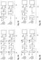
- Figure 1A shows an embodiment of the method and system wherein the plant 6 is illuminated with at least partially polarized, e.g. linearly polarized, illumination light 5.
- the polarized illumination light 5 is generated by applying a polarization filter 4a to light that is generated by a light source 2 that is configured to generated unpolarized light.
- the light source 2 and polarization filter 4a together form a light source 14 that is configured to illuminate the plant 6 with at least partially polarized illumination light 5.
- the illumination light 5 causes response light 7 from the plant.
- the illumination light may be understood to cause the plant to respond by emitting response light.
- the response light may comprise processed illumination light. Such processing may comprise reflecting and/or absorbing and/or changing polarization of the illumination light.
- the response light 7 is detected by a detector 16, which in an example comprises a telescope 10 and an imaging system 12, such as a camera.
- the detector may additionally or alternatively comprise a human with polarizer glasses and/or a light sensor and/or a camera and/or a time-of-flight camera.
- Figure 1A shows the same system yet at a later time instance.
- another polarization filter 4b that has another polarization direction than polarization filter 4a is used.
- the illumination light 5' has a different polarization direction than illumination light 5.
- the response light 7' differs from response light 7.
- Response light 7 may be referred to as first response light and response light 7' as second response light.
- the growth stage of the plant 6 can be determined.
- the figures 1 and 2 schematically show the response light 7 as being transmitted through the plant 6, the response light may also be light that is reflected back from the plant.
- the polarization direction of the illumination light can be changed.
- figure 1A shows only two different polarization directions for the illumination light
- the polarization direction of the illumination light is rotating continuously, for example over 180 degrees.
- Such change of polarization direction of the illumination light may be referred to as dynamic polarized light.
- Such light can be created by a standard light source with mechanically rotatable polarizer mounted in front of it. Then, the polarization direction of the light sequentially shifts ('rotates') at the pace of the rotating external polarizer disk.
- a dynamic polarized light can also be created with a MR 16 light source with embedded mechanically rotatable polarizer. Further, dynamic polarized light can be created with a dual-(or more) polarized spot with electrically adjustable polarization.
- the use of multiple chip-level micro-light sources integrated in a second optics module allows to electrically (with a driver) switch polarization direction at high frequencies.
- Dynamic polarized illumination light can also for example be generated by controlling a liquid crystal based polarizer in front of light source, using illumination based on switchable laser sources (laser generate polarized light) with different orientation or using pixelated light source with the pixels having different polarization directions.
- switchable laser sources laser generate polarized light
- the system of figure 1A is very suitable to create a 'sparkling effect' which makes the polarization active parts of the plant, e.g. trichomes on a Cannabis flower, highly visible and appearing to the user (harvester) or to an automated harvesting machine.
- this sparkling effect is caused by the polarization active parts responding differently to changing polarized illumination light.
- dynamic polarized light can be created using a laser light source (mainly Nd:YAG lasers are linearly polarized, diode lasers are less polarized or even elliptically polarized).
- the laser source can be attached to an arm or combined in a horticulture lamp to scan the plant from top to bottom in order to have an in-depth canopy measurement of ripening.
- Figure 1B shows an embodiment, wherein the detector 16 is configured to polarization filter the response light in different directions subsequently.
- Figure 1B (top) shows a system comprising a detector that polarization filters response light - in this example using a polarization filter 8a having a first polarization direction - in order to obtain first response light 7'.
- Figure 1B (bottom) shows the same system at a later time instance.
- the detector polarization filters the response light 7 in order to obtain differently polarized response light 7'', which may be referred to as second response light.
- a polarization filter 8b is used that has a different polarization direction than filter 8a.
- the growth stage of plant 6 can be determined.
- This embodiment also causes the above-mentioned sparkling effect, which is observable by a human and/or an automated system.
- a user may use an inspection filter of which he can change the polarization (manually, motorized or electrical) to enhance the polarization characteristics of the trichomes as described above.
- the detector 16 may be a special camera with dedicated on-chip polarizers as shown in figure 10 (source: Sony, IEDM2016, lecture number 8.7) .
- Such an imaging system has several differently oriented polarization filters 42 x on respective pixels 44 x of an imaging sensor 46.
- the filters 42 x may be understood to be configured to polarization filter the response light as described herein.
- the filters 42 x are formed during the semiconductor process in which the imaging sensor is formed..
- Further shown are on-chip lenses 40 x for the respective pixels 44 x .
- Such on-chip lenses 40 x may also be referred to as condenser lenses and are positioned in an imaging system on top of the respective image sensor pixels 44 x .
- Such cameras with dedicated on-chip polarizers are mainly targeted at industrial inspection applications where the detection of polarization can be used to highlight defects in materials, however, can also be advantageously used in the context of determining the growth stage of a plant.
- Figure 1C shows an embodiment, wherein both the illumination light 5 is at least partially polarized and wherein the response light 7 is polarization filtered in order to obtain polarized response light 7'.
- the polarization active parts may rotate the direction of the incident illumination light, whereas the rest of the plant may reflect unpolarized light, even if the illumination light is polarized. In such case, the response light will have a relatively strong component in one polarization direction, which can be made visible using a filter 8 as shown in figure 1C .
- Figure 2A shows the system of figure 1C at two respective time instances.
- the detector polarization filters the response light for obtaining differently oriented polarization light at the two time instances.
- two different polarization filters 8a and 8b having different polarization directions are used. If the polarization active parts rotate the polarization direction whereas the rest of the plant reflects unpolarized light, with the change of polarization direction in the detection system 16, the intensity of the response light from the polarization active parts will change, while the intensity of the response light from other parts of the plant will remain substantially the same.
- this embodiment allows to easily detect the polarization active parts.
- response light 7' may be referred to as first response light and response light 7'' may be referred to as second response light.
- Figure 2B shows the system of figure 1C at two respective time instances.
- the light source 14 illuminates the plant with first illumination light 5 at the first time instance and with second illumination light 5' at the second time instance.
- the first and second illumination light have different polarization directions.
- the detector polarization filters the response light 7 at the two time instances in the same way. This embodiment also allows to visualize the polarization active parts of the plant, based on the same principle described with reference to figure 2A .
- the polarization direction of the illumination light at the first time instance is different from the polarization direction of the illumination light at the second time instance and the direction of polarization filtering is different at the first time instance than at the second time instance.
- the relative direction of the illumination light with respect to the direction of polarization filtering, performed by the detector 16, at the first time instance is different from this relative direction at the second time instance. For example, if the angle between the direction of polarization of the illumination light and the polarization filter of the detector at the first time instance is 10 degrees, then this angle is not 10 degrees, e.g. 50 degrees, at the second time instance.
- Figure 2C illustrates an embodiment wherein the light source 14 is configured to generate first illumination light 5 and then illumination light 5'.
- the embodiment illustrates that the light source at a first time instance illuminates the plant 6 with at least partially polarized light 5, referred to as first illumination light, and at a second time instance illuminates the plant 6 with unpolarized light 5', referred to as second illumination light.
- first illumination light at least partially polarized light 5
- second illumination light unpolarized light 5'
- the light source may continuously switch between unpolarized light and polarized light, for example every second.
- Figure 2D illustrates an embodiment wherein the detector is configured to polarization filter the response light for obtaining first response light 7' having a first polarization direction, and to subsequently not polarization filter the response light for obtaining second response light 7 that is unpolarized.
- the detector may continuously switch between a state in which it polarization filters the response light and a state in which it does not polarization filter the response light, for example every second.
- the method involves detecting first response light at a first time instance and second response light at a second time instance and involves influencing the polarization and/or polarization direction of the illumination light and/or the response light somewhere between the first and second time instance, as shown in figures 1A, 1B , 2A, 2B, 2C, 2D
- the first and second response light are detected quickly after each other, for example within 10 minutes, preferably within 1 minute, most preferably within ten seconds.
- system can even change between states faster, e.g. with a 10 - 50 Hz frequency as to make effects highly effective to a human observer.
- These embodiments may be understood to perform such influencing in order to cause differences between the first and second response light. Based on these differences, the polarization active parts can be identified, made visible. Therefore, it is undesirable that other factors contribute to such differences, such as the formation of additional polarization active parts on the plant. This may for example happen if the second response light is detected one week later than the first response light.
- Figure 3A shows a system 20 according to an embodiment.
- the system comprises a light source 14 and a detector 16.
- the light source 14 may be any light source described herein and the detector may be any detector described herein.
- the light source 14 comprises a light source 2 that is configured to generate unpolarized light and a polarization filter 4.
- the light source 14 can thus generate at least partially polarized illumination light 5.
- the detector may be configured to detect response light 7.
- the detector is configured to polarization filter the response light as described herein.
- the system 20 further comprises a data processing system that is configured to determine the growth stage of a plant based on the detected response light 7.
- the detector 16 may be communicatively connected to the data processing system.
- the data processing system may be understood to be a control module of the system 20.
- the data processing system 100 is configured to control the light source 14.
- the data processing system 100 is configured to control the light source 2 and the polarization filter 4.
- the data processing system 100 upon execution of appropriate software, may be configured to switch on and of the light source 2 and/or control an intensity of the light generated by light source 2 and may be configured to control the polarization filter 4.
- the latter may comprise controlling a polarization direction of the filter 4, which may be achieved be mechanically moving, e.g. rotating, the polarization filter 4 and/or by moving the polarization filter 4 in and out of the path of the illumination light 5.
- the data processing system 100 may also be configured, upon executing appropriate software, to control the detector 16, for example by controlling a polarization filter comprised in the detector as described herein. Such control may cause the polarization filter to move, for example rotate, to change its polarization direction and/or move the polarization in and out of the path of the response light 7 entirely.
- the system 20 comprises a display 22.
- the data processing system 100 may also control such display.
- the data processing system causes the display to present an indication of the determined growth stage of the plant, such as an instructions to harvest the plant.
- Figure 3B illustrates an embodiment of the method wherein the light source 14 hangs over the plants that are to be examined and wherein a person detects the response light 7 using a magnifying glass
- the light source 14 may be any light source described herein.
- the methods described herein can be easily realized within existing lighting infrastructure making such a solution cost -efficient and easy maintainable.
- the existing lighting structure for example only needs to be provided with a (controllable) polarization filter in order to form a light source 14 as described herein.
- Figure 3C illustrates an embodiment of the system wherein the light source 14 and the detector 16 are separated.
- the data processing system is not shown, yet may be present in the housing of detector 16, for example within a camera 16, or at least may be communicatively connected to detector 16, for example over a wireless network such as Wi-Fi.
- light signaling can be applied if a determined growth stage indicates that a plant is ready for harvest.
- the light source 14, or any other light may indicate this.
- the light source above the plant may start to flicker or change color in order to indicate to a farmer or automatic harvesting system that that plant can be harvested.
- the data processing system 100 may transmit a message to another device, for example to a handheld device of a farmer, that a particular plant has fully ripened.
- the data processing system can produce overall numbers about ripening of multiple plants when these are all analyzed. These numbers can be used by machine learning aids to cumulate data of previous harvest and correlate them to climate and light history parameters in order to assist/automate the decision making.
- Figure 3D illustrates an embodiment of the system 20 in which it is integrated in a handheld device.
- the system 20 may be understood to be an inspection tool polarizer and human detection for the onsite observation.
- the inspection tool dynamically controls the polarization of the luminaire and observing sensors.
- the user aims the illumination light 5 at the area containing trichomes (e.g. using a "crosshair") and can see the dynamic polarization effect on a built-in display 22, in this example positioned on the back of the hand-held device.
- Figure 4A shows the anatomic properties of a Cannabis plant, in particular of a Cannabis Sativa plant.
- the female flower which is typically consumed, sits at the top of the plant.
- the trichomes which are polarization active develop on these flowers during the growth of the plant, in particular during the ripening of the female flower.
- its optical properties change, in particular its polarization characteristics.
- the change of polarization characteristics can be linked to growth stages.
- a Cannabis flower typically progresses through eight stages while ripening. These eight stages may be understood to be sub-growth stages of the flower ripening growth stage. It should be appreciated that determining a growth stage of a plant may be embodied as determining such sub-growth stage.
- the eight stage of the Cannabis flower ripening are as follows:
- stage 7 to 8 is very fast and difficult to detect by a human.
- the methods disclosed herein enable to accurately determine when stage 8 has been reached.
- Figure 4B illustrates why the trichomes reflect polarized light 7a whereas the rest of the plant, such as a leaf, reflects unpolarized light 7b.
- Light 7a and light 7b together may be understood to constitute response light.
- the leaf may reflect partly polarized 7a and non-polarized 7b light.
- DOP degree of polarization
- the degree of polarization (DOP) is low (more non-polarized light reflected than polarized light) due to light scattering inside the leaf as shown.
- the DOP is high so that the reflected light has more polarization.
- the unpolarized reflected light will de dominant and thus the polarization direction will not affect the intensity of the reflected light.
- the amount of observed light may vary significantly.
- the leaf would still reflect unpolarized light due to internal scattering. So regardless of the polarization of the light source, the leaf will still reflect light with any polarization direction. However, the trichomes will reflect only light with a specific polarization direction. By varying the polarization direction of the light source over time, the observer - even without an explicit polarization filter - would experience the sparkling effect of the trichomes.
- Figure 5 shows an image 30 of a plant, in particular of a Cannabis plant, more in particular a female flower of a Cannabis plant.
- This image 30 may be represented by data that has been obtained by measuring response light. The image may be understood to indicate response light from respective parts of the plant.
- Figure 5 further illustrates that a region of interest 32 may be identified that corresponds to a plant part where polarization active parts expected to form or disappear during growth of the plant. In this example, the region of interest 32 corresponds to the female flower of a Cannabis plant. Subsequent analyses may then be restricted to this region of interest 32, which allows efficient and fast data processing, which in turn allows fast, e.g. real-time, determination of the growth stage of the plant.
- region of interest 32 may be identified based on machine learning techniques. Also, such region of interest 32 may be performed based on 3D sensing technologies. In such case, 3D ranging signals are used to obtain a representation of the three-dimensional shape of the plant. Then, the part of the plant on which polarization active parts are expected to form or disappear may be recognized based on their characteristic morphology.
- Figures 6A and 6B respectively show a first image and a second image of a plant, in particular of a Cannabis plant, more in particular of a female flower of a Cannabis plant.
- figure 6B comprises regions that have a higher intensity than corresponding regions in figure 6A .
- Two image regions in different images may be understood to be corresponding image regions if they both represent the same parts of the plant. This difference between the first and second image is caused by the subsequent detection of first and second response light, wherein the first and second response light differ.
- Such difference between the first and second response light may be achieved by one or more of the methods described above, such as changing the polarization of the illumination, changing the polarization filtering in the detection path, switching between polarized and unpolarized illumination light, switching between detection with polarization filtering and detection without polarization filtering, or a combination of these actions.
- the trichomes which are shown as white dots, have a higher intensity in the second image than in the first image.
- Figure 7 shows how the polarization characteristics may be registered over time to provide historical trends to the grower for decision making on growth control, harvesting or light recipe effectiveness.
- Figure 7 shows a total response light intensity from a particular flower on a particular plant with respect to time.
- Each data point in the graph corresponds to a data set that represents the detected response light at a respective time instance.
- the development over time of the response light may aid in determining a current or even a future growth stage.
- Figure 7 shows for a particular flower that at first the total intensity of the response light intensity is relatively lower and that at some point the total intensity increases until a plateau of constant total light intensity is reached. It could for example be that the flower is ready for harvesting if the total intensity has reached said plateau.
- the growth stage can be determined based on a development over time of the response light, indicated by the plurality of data sets.
- Figure 8A shows an embodiment of the system 20 that comprises an augmented reality system 102.
- display 22 may be understood to be part of the augmented reality system.
- the augmented reality system is configured to present an indication of the determined growth stage of the plant on said display, such that a user looking at the display sees the plant and its determined growth stage.
- the display 22 may be a transparent display.
- the detector 16 may comprise a camera for recording images of the plant.
- the augmented reality system 102 may be configured to at least partially present these recorded images on display 22.
- the flower picker/farmer may go into a greenhouse to check the ripeness of the cannabis flowers and simultaneously pick the flowers that are ready for harvesting.
- the display and the camera are integrated into a head-wearable device, such as AR glasses, so that the picker/farmer can use his/her hands to execute the 'normal' harvesting actions, e.g. picking a flower.
- a head-wearable device such as AR glasses
- the picker may see the 'real' plants and superimposed on that image the locations (the flowers) that are ready to be harvested.
- This information on the ripeness level is created real-time, based on a sensing function embedded onto/into the AR glasses. That sensing function is combined with image processing (and possibly further enables with specific light actuation) based on object (ripe flower) recognition.
- the information as provided to the picker allows him/her to pick the ripe flowers.
- Flowers that are in an earlier stage of development may also be labelled during the data analysis and this information may be stored for later use, leading to a forecast functionality. So, the next day (or next harvest moment) that the picker again enters the greenhouse, the flowers that were judged as 'almost ready to harvest' might be visited by the picker preferentially, e.g. the picker is guided towards these locations in the greenhouse, allowing for a more efficient work flow (preventing looking to plants that are not harvest-ready at all, or for which the flowers have already been harvested).
- the camera on board of the AR glasses may also track the actions of the picker (resulting in stored information on the plants/flowers that have been harvested, who harvested, how much was harvested, when and at what ripeness level, also allowing to capture possible mistakes and control ownership of the flowers that are picked).
- Additional expert input data provided by the pickers might be captured as well with that camera, e.g. based on a gesture-based UI.
- an audio functionality might be used as UI.
- Picker/expert data might e.g. be such parameters as agreement/disagreement with the Machine Learning judgement on ripeness or marking via the UI any type of anomaly in the crop (e.g. disease onset) or in the horticulture system.
- This information may not be needed real-time and may be (later) stored in the overall harvesting tool and made available for a next harvesting cycle or for deeper data analysis (e.g. to optimize forecasting for current and future crops).
- Figure 8B shows an example perception of a user who is looking at the display 22 of the augmented reality system.
- the augmented reality display 22 presents the determined growth stage of the plant next to the plant, in this example in the form of an instruction to the user to harvest the plant.
- the display 22 may also present the images of the plant as for example recorded by a camera 16, in case the display is not transparent. In such case, the indication of the determined growth stage is for example overlayed on the recorded images.
- Fig. 9 depicts a block diagram illustrating a data processing system according to an embodiment.
- the data processing system may be embedded in a single device (e.g. an AR goggles), or distributed on combined wearable device and real-time accessible cloud-implemented functionality (e.g. the storage and data processing). Or alike other options.
- the data processing system 100 may include at least one processor 102 coupled to memory elements 104 through a system bus 106. As such, the data processing system may store program code within memory elements 104. Further, the processor 102 may execute the program code accessed from the memory elements 104 via a system bus 106. In one aspect, the data processing system may be implemented as a computer that is suitable for storing and/or executing program code. It should be appreciated, however, that the data processing system 100 may be implemented in the form of any system including a processor and a memory that is capable of performing the functions described within this specification.
- the memory elements 104 may include one or more physical memory devices such as, for example, local memory 108 and one or more bulk storage devices 110.
- the local memory may refer to random access memory or other non-persistent memory device(s) generally used during actual execution of the program code.
- a bulk storage device may be implemented as a hard drive or other persistent data storage device.
- the processing system 100 may also include one or more cache memories (not shown) that provide temporary storage of at least some program code in order to reduce the number of times program code must be retrieved from the bulk storage device 110 during execution.
- I/O devices depicted as an input device 112 and an output device 114 optionally can be coupled to the data processing system.
- input devices may include, but are not limited to, a keyboard, a pointing device such as a mouse, or the like.
- output devices may include, but are not limited to, a monitor or a display, speakers, or the like.
- Input and/or output devices may be coupled to the data processing system either directly or through intervening I/O controllers.
- the input and the output devices may be implemented as a combined input/output device (illustrated in Fig. 9 with a dashed line surrounding the input device 112 and the output device 114).
- a combined device is a touch sensitive display, also sometimes referred to as a "touch screen display” or simply "touch screen”.
- input to the device may be provided by a movement of a physical object, such as e.g. a stylus or a finger of a user, on or near the touch screen display.
- a network adapter 116 may also be coupled to the data processing system to enable it to become coupled to other systems, computer systems, remote network devices, and/or remote storage devices through intervening private or public networks.
- the memory elements 104 may store an application 118.
- the application 118 may be stored in the local memory 108, the one or more bulk storage devices 110, or apart from the local memory and the bulk storage devices.
- the data processing system 100 may further execute an operating system (not shown in Fig. 9 ) that can facilitate execution of the application 118.
- the application 118 being implemented in the form of executable program code, can be executed by the data processing system 100, e.g., by the processor 102. Responsive to executing the application, the data processing system 100 may be configured to perform one or more operations or method steps described herein.
- the data processing system 100 may represent an augmented reality system described herein.
- the data processing system 100 may represent a client data processing system.
- the application 118 may represent a client application that, when executed, configures the data processing system 100 to perform the various functions described herein with reference to a "client".
- client can include, but are not limited to, a personal computer, a portable computer, a mobile phone, or the like.
- the data processing system 100 may represent a server.
- the data processing system may represent an (HTTP) server, in which case the application 118, when executed, may configure the data processing system to perform (HTTP) server operations.
- HTTP HyperText Transfer Protocol
- Various embodiments of the invention may be implemented as a program product for use with a computer system, where the program(s) of the program product define functions of the embodiments (including the methods described herein).
- the program(s) can be contained on a variety of non-transitory computer-readable storage media, where, as used herein, the expression "non-transitory computer readable storage media" comprises all computer-readable media, with the sole exception being a transitory, propagating signal.
- the program(s) can be contained on a variety of transitory computer-readable storage media.
- Illustrative computer-readable storage media include, but are not limited to: (i) non-writable storage media (e.g., read-only memory devices within a computer such as CD-ROM disks readable by a CD-ROM drive, ROM chips or any type of solid-state non-volatile semiconductor memory) on which information is permanently stored; and (ii) writable storage media (e.g., flash memory, floppy disks within a diskette drive or hard-disk drive or any type of solid-state random-access semiconductor memory) on which alterable information is stored.
- the computer program may be run on the processor 102 described herein.
Landscapes
- Life Sciences & Earth Sciences (AREA)
- Immunology (AREA)
- Physics & Mathematics (AREA)
- Chemical & Material Sciences (AREA)
- Analytical Chemistry (AREA)
- Biochemistry (AREA)
- General Health & Medical Sciences (AREA)
- Health & Medical Sciences (AREA)
- General Physics & Mathematics (AREA)
- Pathology (AREA)
- Biodiversity & Conservation Biology (AREA)
- Botany (AREA)
- Ecology (AREA)
- Forests & Forestry (AREA)
- Environmental Sciences (AREA)
- Investigating Or Analysing Materials By Optical Means (AREA)
- Cultivation Of Plants (AREA)
Applications Claiming Priority (2)
| Application Number | Priority Date | Filing Date | Title |
|---|---|---|---|
| EP20183964 | 2020-07-03 | ||
| PCT/EP2021/066385 WO2022002610A1 (en) | 2020-07-03 | 2021-06-17 | Methods and systems for determining the growth stage of a plant |
Publications (2)
| Publication Number | Publication Date |
|---|---|
| EP4175459A1 EP4175459A1 (en) | 2023-05-10 |
| EP4175459B1 true EP4175459B1 (en) | 2025-03-19 |
Family
ID=71465212
Family Applications (1)
| Application Number | Title | Priority Date | Filing Date |
|---|---|---|---|
| EP21733964.7A Active EP4175459B1 (en) | 2020-07-03 | 2021-06-17 | Methods and systems for determining the growth stage of a plant |
Country Status (7)
| Country | Link |
|---|---|
| US (1) | US12385844B2 (da) |
| EP (1) | EP4175459B1 (da) |
| CN (1) | CN115811935A (da) |
| DK (1) | DK4175459T3 (da) |
| ES (1) | ES3029558T3 (da) |
| PT (1) | PT4175459T (da) |
| WO (1) | WO2022002610A1 (da) |
Families Citing this family (4)
| Publication number | Priority date | Publication date | Assignee | Title |
|---|---|---|---|---|
| WO2019152424A1 (en) * | 2018-01-31 | 2019-08-08 | Monsanto Technology Llc | Systems and methods for quantitative phenotype analysis |
| EP4468853B1 (en) | 2022-01-25 | 2025-07-23 | Signify Holding B.V. | Method and system for instructing a user for post-harvest trimming a bud |
| CN119164888B (zh) * | 2024-11-22 | 2025-02-18 | 北京市农林科学院智能装备技术研究中心 | 一种作物长势干旱胁迫检测系统及方法 |
| CN121014402A (zh) * | 2025-08-18 | 2025-11-28 | 内蒙古工业大学 | 一种用于智能植物培养装置的温度光照控制方法 |
Family Cites Families (25)
| Publication number | Priority date | Publication date | Assignee | Title |
|---|---|---|---|---|
| USRE31023E (en) * | 1975-04-11 | 1982-09-07 | Advanced Decision Handling, Inc. | Highly automated agricultural production system |
| US4569150A (en) * | 1983-10-31 | 1986-02-11 | Board Of Trustees Operating Michigan State University | Method and apparatus for optimization of growth of plants |
| DE3602035A1 (de) * | 1985-01-31 | 1986-08-07 | Mitsubishi Denki K.K., Tokio/Tokyo | Anlage zum anbauen und zuechten von pflanzen |
| WO2008068699A1 (en) * | 2006-12-07 | 2008-06-12 | Philips Intellectual Property & Standards Gmbh | Controlling device for a greenhouse |
| JP2011167163A (ja) * | 2010-02-22 | 2011-09-01 | Pasuko:Kk | 水稲収量予測モデル生成方法、及び水稲収量予測方法 |
| US10408740B2 (en) | 2014-06-15 | 2019-09-10 | The State Of Israel, Ministry Of Agriculture & Rural Development Agricultural Research Organization | Method for huanglongbing (HLB) detection |
| US9886016B2 (en) * | 2015-01-08 | 2018-02-06 | International Business Machines Corporation | Automated irrigation control system |
| US20180206422A1 (en) * | 2015-07-17 | 2018-07-26 | Urban Crop Solutions Bvba | Industrial plant growing facility and methods of use |
| JP6834966B2 (ja) | 2015-10-08 | 2021-02-24 | ソニー株式会社 | 情報処理装置、及び、情報処理方法、並びにプログラム |
| JP2017134585A (ja) | 2016-01-27 | 2017-08-03 | 秋田県 | 収穫適期判定支援装置及び収穫適期判定支援プログラム |
| EP3459344A4 (en) * | 2016-05-18 | 2019-12-11 | Sony Corporation | INFORMATION PROCESSING DEVICE, PROGRAM AND INFORMATION PROCESSING METHOD |
| US11166415B2 (en) * | 2016-07-26 | 2021-11-09 | Sensor Electronic Technology, Inc. | Plant growth with radiation-based mildew and/or bacteria control |
| CN109561656A (zh) | 2016-08-15 | 2019-04-02 | 富士胶片株式会社 | 植物生长用层叠薄膜及植物生长用照明装置 |
| JP6697681B2 (ja) | 2016-08-17 | 2020-05-27 | ソニー株式会社 | 検査装置、検査方法、およびプログラム |
| US11538099B2 (en) * | 2016-09-21 | 2022-12-27 | Iunu, Inc. | Online data market for automated plant growth input curve scripts |
| EP3560295B1 (en) | 2016-12-20 | 2020-08-26 | Signify Holding B.V. | Multi-mode polarized spot with electrically adjustable polarization state |
| WO2018132814A1 (en) * | 2017-01-16 | 2018-07-19 | Iron Ox, Inc. | Method for automatically redistributing plants throughout an agricultural facility |
| CN108323295B (zh) * | 2017-12-05 | 2019-12-03 | 江苏大学 | 一种基于多尺度生境信息的苗期作物水肥检测和控制方法及装置 |
| CN108376419B (zh) * | 2017-12-11 | 2020-06-26 | 江苏大学 | 一种盆栽生菜的综合长势监测方法及装置 |
| US11663414B2 (en) * | 2018-02-20 | 2023-05-30 | Fluence Bioengineering, Inc. | Controlled agricultural systems and methods of managing agricultural systems |
| US20190259108A1 (en) | 2018-02-20 | 2019-08-22 | Osram Gmbh | Controlled Agricultural Systems and Methods of Managing Agricultural Systems |
| US11074447B1 (en) * | 2018-07-13 | 2021-07-27 | Hana Resources, Inc. | Land analysis system using drone-captured data |
| CN108803755A (zh) | 2018-08-06 | 2018-11-13 | 华超 | 一种基于增强现实技术应用的温室控制系统 |
| JP7181312B2 (ja) * | 2018-12-14 | 2022-11-30 | 富士フイルム株式会社 | 植物育成用灯具 |
| US12007374B2 (en) * | 2020-05-15 | 2024-06-11 | King Abdullah University Of Science And Technology | Internet of flora things (IoFT) |
-
2021
- 2021-06-17 CN CN202180047416.7A patent/CN115811935A/zh active Pending
- 2021-06-17 DK DK21733964.7T patent/DK4175459T3/da active
- 2021-06-17 ES ES21733964T patent/ES3029558T3/es active Active
- 2021-06-17 EP EP21733964.7A patent/EP4175459B1/en active Active
- 2021-06-17 US US18/009,715 patent/US12385844B2/en active Active
- 2021-06-17 PT PT217339647T patent/PT4175459T/pt unknown
- 2021-06-17 WO PCT/EP2021/066385 patent/WO2022002610A1/en not_active Ceased
Also Published As
| Publication number | Publication date |
|---|---|
| WO2022002610A1 (en) | 2022-01-06 |
| CN115811935A (zh) | 2023-03-17 |
| US12385844B2 (en) | 2025-08-12 |
| ES3029558T3 (en) | 2025-06-24 |
| EP4175459A1 (en) | 2023-05-10 |
| PT4175459T (pt) | 2025-05-06 |
| US20230243756A1 (en) | 2023-08-03 |
| DK4175459T3 (da) | 2025-05-05 |
Similar Documents
| Publication | Publication Date | Title |
|---|---|---|
| EP4175459B1 (en) | Methods and systems for determining the growth stage of a plant | |
| US9116125B2 (en) | Method, apparatus and system for diagnosis of stress and disease in higher plants | |
| US20180373937A1 (en) | Methods and systems for automated micro farming | |
| WO2014100502A1 (en) | Methods and systems for automated micro farming | |
| US12087031B2 (en) | Method and device for analyzing plants | |
| JP2012208839A (ja) | 植物体の画像領域抽出方法、植物体の画像領域抽出装置、および植物体の生育監視システム | |
| CN103439270A (zh) | 一种高光谱图像检测桃果实冷害的装置和方法 | |
| JP6487681B2 (ja) | 計測装置、ネットワークシステム、計測方法およびプログラム | |
| CN109324509A (zh) | 信息调控方法、装置及系统 | |
| KR102742949B1 (ko) | 작물 색상 정보 분석을 통한 작물 정보 제공 방법 및 이를 지원하는 장치 | |
| JP2006226775A (ja) | 果実の食味成分評価方法及び評価装置 | |
| US12019022B2 (en) | Systems and methods for distinguishing fertile plant specimens from sterile plant specimens | |
| JP7058816B1 (ja) | 光学検出装置及び該光学検出装置を備えたシステム | |
| US20210018481A1 (en) | Method and system for estimation of fruitlet drop | |
| US11768152B2 (en) | Information processing system and spectroscopic measuring instrument | |
| EP4468853B1 (en) | Method and system for instructing a user for post-harvest trimming a bud | |
| US20220099578A1 (en) | System for early detection of plant disease | |
| JP5938768B2 (ja) | 植物の生育状態を診断する方法及びこれに用いられる装置 | |
| CN111060471B (zh) | 一种柑橘早期腐烂的透射成像检测方法 | |
| KR20190071204A (ko) | 통합 식물체 재배환경 분석시스템 | |
| WO2025199857A1 (en) | System including devices and algorithms to evaluate scalp and hair health | |
| CN206876555U (zh) | 一种用于采集马铃薯激光图像的装置 | |
| RO138315A0 (ro) | Identificarea timpurie a integrităţii frunzei viţei de vie folosind senzori spectrali | |
| Malithi De Silva et al. | Early Plant Disease Detection Using Infrared and Mobile Photographs | |
| Lin et al. | Quantitative Phenotyping of Water-Stressed Tomato Plants Using Frequency-Domain Fluorescence Lifetime Imaging Microscope (FD-FLIM) |
Legal Events
| Date | Code | Title | Description |
|---|---|---|---|
| STAA | Information on the status of an ep patent application or granted ep patent |
Free format text: STATUS: UNKNOWN |
|
| STAA | Information on the status of an ep patent application or granted ep patent |
Free format text: STATUS: THE INTERNATIONAL PUBLICATION HAS BEEN MADE |
|
| PUAI | Public reference made under article 153(3) epc to a published international application that has entered the european phase |
Free format text: ORIGINAL CODE: 0009012 |
|
| STAA | Information on the status of an ep patent application or granted ep patent |
Free format text: STATUS: REQUEST FOR EXAMINATION WAS MADE |
|
| 17P | Request for examination filed |
Effective date: 20230203 |
|
| AK | Designated contracting states |
Kind code of ref document: A1 Designated state(s): AL AT BE BG CH CY CZ DE DK EE ES FI FR GB GR HR HU IE IS IT LI LT LU LV MC MK MT NL NO PL PT RO RS SE SI SK SM TR |
|
| DAV | Request for validation of the european patent (deleted) | ||
| DAX | Request for extension of the european patent (deleted) | ||
| GRAP | Despatch of communication of intention to grant a patent |
Free format text: ORIGINAL CODE: EPIDOSNIGR1 |
|
| STAA | Information on the status of an ep patent application or granted ep patent |
Free format text: STATUS: GRANT OF PATENT IS INTENDED |
|
| INTG | Intention to grant announced |
Effective date: 20241016 |
|
| GRAS | Grant fee paid |
Free format text: ORIGINAL CODE: EPIDOSNIGR3 |
|
| GRAA | (expected) grant |
Free format text: ORIGINAL CODE: 0009210 |
|
| STAA | Information on the status of an ep patent application or granted ep patent |
Free format text: STATUS: THE PATENT HAS BEEN GRANTED |
|
| AK | Designated contracting states |
Kind code of ref document: B1 Designated state(s): AL AT BE BG CH CY CZ DE DK EE ES FI FR GB GR HR HU IE IS IT LI LT LU LV MC MK MT NL NO PL PT RO RS SE SI SK SM TR |
|
| P01 | Opt-out of the competence of the unified patent court (upc) registered |
Free format text: CASE NUMBER: APP_6341/2025 Effective date: 20250206 |
|
| REG | Reference to a national code |
Ref country code: GB Ref legal event code: FG4D |
|
| REG | Reference to a national code |
Ref country code: CH Ref legal event code: EP |
|
| REG | Reference to a national code |
Ref country code: IE Ref legal event code: FG4D |
|
| REG | Reference to a national code |
Ref country code: DE Ref legal event code: R096 Ref document number: 602021027820 Country of ref document: DE |
|
| REG | Reference to a national code |
Ref country code: DK Ref legal event code: T3 Effective date: 20250428 |
|
| REG | Reference to a national code |
Ref country code: PT Ref legal event code: SC4A Ref document number: 4175459 Country of ref document: PT Date of ref document: 20250506 Kind code of ref document: T Free format text: AVAILABILITY OF NATIONAL TRANSLATION Effective date: 20250428 |
|
| REG | Reference to a national code |
Ref country code: NL Ref legal event code: FP |
|
| REG | Reference to a national code |
Ref country code: ES Ref legal event code: FG2A Ref document number: 3029558 Country of ref document: ES Kind code of ref document: T3 Effective date: 20250624 |
|
| PG25 | Lapsed in a contracting state [announced via postgrant information from national office to epo] |
Ref country code: RS Free format text: LAPSE BECAUSE OF FAILURE TO SUBMIT A TRANSLATION OF THE DESCRIPTION OR TO PAY THE FEE WITHIN THE PRESCRIBED TIME-LIMIT Effective date: 20250619 |
|
| PG25 | Lapsed in a contracting state [announced via postgrant information from national office to epo] |
Ref country code: FI Free format text: LAPSE BECAUSE OF FAILURE TO SUBMIT A TRANSLATION OF THE DESCRIPTION OR TO PAY THE FEE WITHIN THE PRESCRIBED TIME-LIMIT Effective date: 20250319 |
|
| PGFP | Annual fee paid to national office [announced via postgrant information from national office to epo] |
Ref country code: GB Payment date: 20250617 Year of fee payment: 5 Ref country code: DK Payment date: 20250619 Year of fee payment: 5 |
|
| REG | Reference to a national code |
Ref country code: LT Ref legal event code: MG9D |
|
| PG25 | Lapsed in a contracting state [announced via postgrant information from national office to epo] |
Ref country code: NO Free format text: LAPSE BECAUSE OF FAILURE TO SUBMIT A TRANSLATION OF THE DESCRIPTION OR TO PAY THE FEE WITHIN THE PRESCRIBED TIME-LIMIT Effective date: 20250619 |
|
| PGFP | Annual fee paid to national office [announced via postgrant information from national office to epo] |
Ref country code: NL Payment date: 20250624 Year of fee payment: 5 |
|
| PG25 | Lapsed in a contracting state [announced via postgrant information from national office to epo] |
Ref country code: HR Free format text: LAPSE BECAUSE OF FAILURE TO SUBMIT A TRANSLATION OF THE DESCRIPTION OR TO PAY THE FEE WITHIN THE PRESCRIBED TIME-LIMIT Effective date: 20250319 |
|
| PG25 | Lapsed in a contracting state [announced via postgrant information from national office to epo] |
Ref country code: LV Free format text: LAPSE BECAUSE OF FAILURE TO SUBMIT A TRANSLATION OF THE DESCRIPTION OR TO PAY THE FEE WITHIN THE PRESCRIBED TIME-LIMIT Effective date: 20250319 |
|
| PGFP | Annual fee paid to national office [announced via postgrant information from national office to epo] |
Ref country code: PT Payment date: 20250603 Year of fee payment: 5 |
|
| PGFP | Annual fee paid to national office [announced via postgrant information from national office to epo] |
Ref country code: FR Payment date: 20250624 Year of fee payment: 5 |
|
| PG25 | Lapsed in a contracting state [announced via postgrant information from national office to epo] |
Ref country code: GR Free format text: LAPSE BECAUSE OF FAILURE TO SUBMIT A TRANSLATION OF THE DESCRIPTION OR TO PAY THE FEE WITHIN THE PRESCRIBED TIME-LIMIT Effective date: 20250620 Ref country code: BG Free format text: LAPSE BECAUSE OF FAILURE TO SUBMIT A TRANSLATION OF THE DESCRIPTION OR TO PAY THE FEE WITHIN THE PRESCRIBED TIME-LIMIT Effective date: 20250319 |
|
| REG | Reference to a national code |
Ref country code: AT Ref legal event code: MK05 Ref document number: 1776136 Country of ref document: AT Kind code of ref document: T Effective date: 20250319 |
|
| PG25 | Lapsed in a contracting state [announced via postgrant information from national office to epo] |
Ref country code: SE Free format text: LAPSE BECAUSE OF FAILURE TO SUBMIT A TRANSLATION OF THE DESCRIPTION OR TO PAY THE FEE WITHIN THE PRESCRIBED TIME-LIMIT Effective date: 20250319 |
|
| PG25 | Lapsed in a contracting state [announced via postgrant information from national office to epo] |
Ref country code: SM Free format text: LAPSE BECAUSE OF FAILURE TO SUBMIT A TRANSLATION OF THE DESCRIPTION OR TO PAY THE FEE WITHIN THE PRESCRIBED TIME-LIMIT Effective date: 20250319 |
|
| PGFP | Annual fee paid to national office [announced via postgrant information from national office to epo] |
Ref country code: ES Payment date: 20250710 Year of fee payment: 5 |
|
| PGFP | Annual fee paid to national office [announced via postgrant information from national office to epo] |
Ref country code: DE Payment date: 20250827 Year of fee payment: 5 |
|
| PG25 | Lapsed in a contracting state [announced via postgrant information from national office to epo] |
Ref country code: IT Free format text: LAPSE BECAUSE OF FAILURE TO SUBMIT A TRANSLATION OF THE DESCRIPTION OR TO PAY THE FEE WITHIN THE PRESCRIBED TIME-LIMIT Effective date: 20250319 Ref country code: PL Free format text: LAPSE BECAUSE OF FAILURE TO SUBMIT A TRANSLATION OF THE DESCRIPTION OR TO PAY THE FEE WITHIN THE PRESCRIBED TIME-LIMIT Effective date: 20250319 |
|
| PG25 | Lapsed in a contracting state [announced via postgrant information from national office to epo] |
Ref country code: AT Free format text: LAPSE BECAUSE OF FAILURE TO SUBMIT A TRANSLATION OF THE DESCRIPTION OR TO PAY THE FEE WITHIN THE PRESCRIBED TIME-LIMIT Effective date: 20250319 |
|
| PGFP | Annual fee paid to national office [announced via postgrant information from national office to epo] |
Ref country code: CH Payment date: 20250701 Year of fee payment: 5 |
|
| PG25 | Lapsed in a contracting state [announced via postgrant information from national office to epo] |
Ref country code: EE Free format text: LAPSE BECAUSE OF FAILURE TO SUBMIT A TRANSLATION OF THE DESCRIPTION OR TO PAY THE FEE WITHIN THE PRESCRIBED TIME-LIMIT Effective date: 20250319 Ref country code: CZ Free format text: LAPSE BECAUSE OF FAILURE TO SUBMIT A TRANSLATION OF THE DESCRIPTION OR TO PAY THE FEE WITHIN THE PRESCRIBED TIME-LIMIT Effective date: 20250319 |
|
| PG25 | Lapsed in a contracting state [announced via postgrant information from national office to epo] |
Ref country code: RO Free format text: LAPSE BECAUSE OF FAILURE TO SUBMIT A TRANSLATION OF THE DESCRIPTION OR TO PAY THE FEE WITHIN THE PRESCRIBED TIME-LIMIT Effective date: 20250319 |
|
| PG25 | Lapsed in a contracting state [announced via postgrant information from national office to epo] |
Ref country code: SK Free format text: LAPSE BECAUSE OF FAILURE TO SUBMIT A TRANSLATION OF THE DESCRIPTION OR TO PAY THE FEE WITHIN THE PRESCRIBED TIME-LIMIT Effective date: 20250319 |
|
| PG25 | Lapsed in a contracting state [announced via postgrant information from national office to epo] |
Ref country code: IS Free format text: LAPSE BECAUSE OF FAILURE TO SUBMIT A TRANSLATION OF THE DESCRIPTION OR TO PAY THE FEE WITHIN THE PRESCRIBED TIME-LIMIT Effective date: 20250719 |
|
| REG | Reference to a national code |
Ref country code: DE Ref legal event code: R097 Ref document number: 602021027820 Country of ref document: DE |
|
| PLBE | No opposition filed within time limit |
Free format text: ORIGINAL CODE: 0009261 |
|
| STAA | Information on the status of an ep patent application or granted ep patent |
Free format text: STATUS: NO OPPOSITION FILED WITHIN TIME LIMIT |
|
| REG | Reference to a national code |
Ref country code: CH Ref legal event code: L10 Free format text: ST27 STATUS EVENT CODE: U-0-0-L10-L00 (AS PROVIDED BY THE NATIONAL OFFICE) Effective date: 20260128 |
|
| PG25 | Lapsed in a contracting state [announced via postgrant information from national office to epo] |
Ref country code: MC Free format text: LAPSE BECAUSE OF FAILURE TO SUBMIT A TRANSLATION OF THE DESCRIPTION OR TO PAY THE FEE WITHIN THE PRESCRIBED TIME-LIMIT Effective date: 20250319 |
|
| PG25 | Lapsed in a contracting state [announced via postgrant information from national office to epo] |
Ref country code: LU Free format text: LAPSE BECAUSE OF NON-PAYMENT OF DUE FEES Effective date: 20250617 |
|
| 26N | No opposition filed |
Effective date: 20251222 |
|
| REG | Reference to a national code |
Ref country code: BE Ref legal event code: MM Effective date: 20250630 |
|
| PG25 | Lapsed in a contracting state [announced via postgrant information from national office to epo] |
Ref country code: IE Free format text: LAPSE BECAUSE OF NON-PAYMENT OF DUE FEES Effective date: 20250617 |
|
| PG25 | Lapsed in a contracting state [announced via postgrant information from national office to epo] |
Ref country code: BE Free format text: LAPSE BECAUSE OF NON-PAYMENT OF DUE FEES Effective date: 20250630 |