EP4175567B1 - Dispositif de lithotripsie et procédé de fonctionnement en mode test d'un dispositif de lithotripsie - Google Patents
Dispositif de lithotripsie et procédé de fonctionnement en mode test d'un dispositif de lithotripsie Download PDFInfo
- Publication number
- EP4175567B1 EP4175567B1 EP21746651.5A EP21746651A EP4175567B1 EP 4175567 B1 EP4175567 B1 EP 4175567B1 EP 21746651 A EP21746651 A EP 21746651A EP 4175567 B1 EP4175567 B1 EP 4175567B1
- Authority
- EP
- European Patent Office
- Prior art keywords
- sonotrode
- lithotripsy device
- transmission direction
- lithotripsy
- ultrasonic
- Prior art date
- Legal status (The legal status is an assumption and is not a legal conclusion. Google has not performed a legal analysis and makes no representation as to the accuracy of the status listed.)
- Active
Links
Images


Classifications
-
- A—HUMAN NECESSITIES
- A61—MEDICAL OR VETERINARY SCIENCE; HYGIENE
- A61B—DIAGNOSIS; SURGERY; IDENTIFICATION
- A61B17/00—Surgical instruments, devices or methods
- A61B17/22—Implements for squeezing-off ulcers or the like on inner organs of the body; Implements for scraping-out cavities of body organs, e.g. bones; for invasive removal or destruction of calculus using mechanical vibrations; for removing obstructions in blood vessels, not otherwise provided for
- A61B17/22004—Implements for squeezing-off ulcers or the like on inner organs of the body; Implements for scraping-out cavities of body organs, e.g. bones; for invasive removal or destruction of calculus using mechanical vibrations; for removing obstructions in blood vessels, not otherwise provided for using mechanical vibrations, e.g. ultrasonic shock waves
- A61B17/22012—Implements for squeezing-off ulcers or the like on inner organs of the body; Implements for scraping-out cavities of body organs, e.g. bones; for invasive removal or destruction of calculus using mechanical vibrations; for removing obstructions in blood vessels, not otherwise provided for using mechanical vibrations, e.g. ultrasonic shock waves in direct contact with, or very close to, the obstruction or concrement
-
- A—HUMAN NECESSITIES
- A61—MEDICAL OR VETERINARY SCIENCE; HYGIENE
- A61B—DIAGNOSIS; SURGERY; IDENTIFICATION
- A61B17/00—Surgical instruments, devices or methods
- A61B17/22—Implements for squeezing-off ulcers or the like on inner organs of the body; Implements for scraping-out cavities of body organs, e.g. bones; for invasive removal or destruction of calculus using mechanical vibrations; for removing obstructions in blood vessels, not otherwise provided for
- A61B17/22004—Implements for squeezing-off ulcers or the like on inner organs of the body; Implements for scraping-out cavities of body organs, e.g. bones; for invasive removal or destruction of calculus using mechanical vibrations; for removing obstructions in blood vessels, not otherwise provided for using mechanical vibrations, e.g. ultrasonic shock waves
- A61B2017/22005—Effects, e.g. on tissue
- A61B2017/22011—Combined types of vibration, e.g. ultrasonic and electrohydraulic
-
- A—HUMAN NECESSITIES
- A61—MEDICAL OR VETERINARY SCIENCE; HYGIENE
- A61B—DIAGNOSIS; SURGERY; IDENTIFICATION
- A61B17/00—Surgical instruments, devices or methods
- A61B17/22—Implements for squeezing-off ulcers or the like on inner organs of the body; Implements for scraping-out cavities of body organs, e.g. bones; for invasive removal or destruction of calculus using mechanical vibrations; for removing obstructions in blood vessels, not otherwise provided for
- A61B17/22004—Implements for squeezing-off ulcers or the like on inner organs of the body; Implements for scraping-out cavities of body organs, e.g. bones; for invasive removal or destruction of calculus using mechanical vibrations; for removing obstructions in blood vessels, not otherwise provided for using mechanical vibrations, e.g. ultrasonic shock waves
- A61B17/22012—Implements for squeezing-off ulcers or the like on inner organs of the body; Implements for scraping-out cavities of body organs, e.g. bones; for invasive removal or destruction of calculus using mechanical vibrations; for removing obstructions in blood vessels, not otherwise provided for using mechanical vibrations, e.g. ultrasonic shock waves in direct contact with, or very close to, the obstruction or concrement
- A61B2017/22014—Implements for squeezing-off ulcers or the like on inner organs of the body; Implements for scraping-out cavities of body organs, e.g. bones; for invasive removal or destruction of calculus using mechanical vibrations; for removing obstructions in blood vessels, not otherwise provided for using mechanical vibrations, e.g. ultrasonic shock waves in direct contact with, or very close to, the obstruction or concrement the ultrasound transducer being outside patient's body; with an ultrasound transmission member; with a wave guide; with a vibrated guide wire
Definitions
- the invention relates to a lithotripsy device, in particular an intracorporeal lithotripsy device, according to the preamble of claim 1 and to a method for extracorporeal test operation of a lithotripsy device according to the preamble of claim 19. Surgical or therapeutic methods are not claimed.
- a lithotripsy device is already known from the prior art, comprising a sonotrode, which includes a sonotrode head and a sonotrode tip, and an ultrasonic horn.
- the ultrasonic horn is configured to transmit and focus ultrasonic waves onto the sonotrode head along a transmission direction.
- the sonotrode is configured to guide the ultrasonic waves from the sonotrode head to the sonotrode tip along the same transmission direction.
- EP 1 163 883 A1 Cl aims a device for removing body stones using an intracorporeal lithotripter, in which a metal probe configured as a waveguide is excited to longitudinal vibration by means of an electrically controlled ultrasonic transducer, and this vibration excitation can be switched to the formation of a shock or pressure wave in the metal probe controlled by a reversibly driven impactor.
- the generated ultrasonic vibrations are focused in the distal direction by the horn of the ultrasonic transducer and transmitted further in the distal direction from the metal probe to the probe tip for the removal of body stones.
- a sonotrode can be excited to longitudinal vibration by means of an ultrasonic transducer.
- An axially aligned guide sleeve for a reversibly driven impactor is arranged proximal to the hollow sonotrode. This impactor can act on a mass body of a shock probe housed in the cavity of the sonotrode.
- the vibration excitation and the shock excitation also occur in the same distal direction.
- WO 2019/141822 A1 relates to a device for crushing body stones with a probe and a drive unit for deflecting the probe along its longitudinal extent, wherein the drive unit has a first drive device for periodically deflecting the probe and a second drive device for pulse-shaped alignment of the probe, wherein the transmission of the periodic deflection and the pulse-shaped deflection both takes place in the direction of the longitudinal axis of the sonotrode to the sonotrode tip.
- the object of the invention is, in particular, to provide a generic device with improved properties with regard to efficiency, in particular installation space efficiency and/or component efficiency.
- This object is achieved according to the invention by a device having the features of patent claim 1 and a method having the features of patent claim 19, while advantageous embodiments and further developments of the invention can be found in the subclaims.
- the invention relates to a lithotripsy device, in particular an intracorporeal lithotripsy device, with at least one sonotrode, which comprises at least one sonotrode head for receiving ultrasonic waves and at least one sonotrode tip, which is connected to the sonotrode head, for acting on concretions, and with an ultrasonic horn.
- the ultrasonic horn is configured to transmit and focus ultrasonic waves at least indirectly onto the sonotrode head along a first transmission direction
- the sonotrode is configured to transmit the ultrasonic waves from the sonotrode head to the sonotrode tip along at least one second transmission direction, which is different from the first transmission direction
- a “lithotripsy device” is understood to mean, in particular, a preferably functional component, for example, a subassembly and/or a structural and/or functional component of a lithotripter.
- the lithotripsy device can form the lithotripter at least partially, preferably at least to a large extent, and particularly preferably completely.
- the lithotripsy device is particularly designed to fragment calculi.
- "Calculi” is understood to mean, in particular, solid structures formed in the body by deposition, which consist at least partially, preferably at least to a large extent, and particularly preferably completely, of salts, such as kidney stones, gallstones, urinary stones, salivary stones, or the like.
- an “intracorporeal lithotripsy device” is understood to mean, in particular, a lithotripsy device that is designed to be inserted at least partially and preferably at least to a large extent into a particularly artificial and/or natural opening, in particular a body orifice, in order to fragment and/or remove calculi accumulated there.
- Configured should be understood in particular to mean specifically programmed, provided, designed, configured, and/or equipped. The fact that a component is configured for a specific function should be understood in particular to mean that the component fulfills and/or performs this specific function in at least one application and/or operating state.
- the expression "at least to a large extent” should be understood in particular to mean at least 55%, preferably at least 65%, more preferably at least 70%, particularly preferably at least 85%, and most preferably at least 95%, and advantageously completely, particularly with reference to a volume and/or mass of a component.
- a “sonotrode” should be understood in particular to mean a rod-, tube-, and/or hose-shaped probe configured for examination and/or treatment.
- the sonotrode is preferably designed as an intracorporeal sonotrode.
- an “intracorporeal sonotrode” is understood to mean, in particular, a sonotrode that is designed to be inserted at least partially, preferably at least to a large extent, and particularly preferably completely into a particularly artificial and/or natural opening, in particular a body opening, in order, for example, to fragment and/or remove concretions accumulated there.
- the sonotrode has, in particular, at least one sonotrode tip that is designed to directly contact concretions and transmit ultrasonic waves to them. Instead of direct exposure, an at least indirect exposure of the concretions by the sonotrode is also conceivable.
- “At least indirectly” is understood to mean, in particular, indirect, but preferably also direct, i.e., in particular, immediate.
- the sonotrode head and the sonotrode tip of the sonotrode are preferably formed separately from one another.
- the sonotrode head and the sonotrode tip could be formed and/or connected in one piece.
- a component and "A further component is at least partially formed and/or connected in one piece” is to be understood in particular as meaning that at least one element and/or part of the component and at least one element and/or part of the further component are formed and/or connected in one piece with one another.
- the lithotripsy device in particular comprises at least one ultrasonic generator.
- the ultrasonic generator is configured to provide and/or generate the ultrasonic waves.
- the ultrasonic generator has at least one, preferably at least two, particularly preferably at least three, and most preferably a plurality of ultrasonic actuators.
- the ultrasonic actuator is preferably designed as a piezo actuator.
- the ultrasonic generator comprises at least two ultrasonic actuators, these are at least indirectly adjacent to one another to advantageously increase the intensity of the generated ultrasonic waves.
- the ultrasonic generator is in particular operatively connected to the ultrasonic horn.
- the ultrasonic horn is at least indirectly adjacent to the ultrasonic generator.
- the ultrasonic horn is preferably made at least partially, preferably at least largely, and particularly preferably entirely of metal, such as iron, titanium, steel, or a metal alloy.
- Ultrasonic waves are understood to mean, in particular, sound waves that lie above the audible frequency range for humans.
- the ultrasonic wave has, in particular, an ultrasonic frequency of at least 10 kHz, preferably at least 15 kHz, and particularly preferably of at least 20 kHz and/or of at most 100 kHz, preferably of at most 80 kHz, and particularly preferably of at most 56 kHz.
- the ultrasonic frequency of the ultrasonic waves is most preferably between 22 kHz and 55 kHz.
- a "transmission direction” is to be understood in particular as a direction which corresponds to a transmission of ultrasonic waves along a component.
- the first transmission direction is at least substantially parallel to a main extension direction of the ultrasonic horn.
- the second transmission direction is in particular at least substantially parallel to a main extension direction of the sonotrode.
- a "main extension direction" of a component is to be understood in particular as a direction which runs parallel to a longest edge of a smallest imaginary cuboid which just completely encloses the component.
- "At least substantially parallel” is to be understood in particular as including an angle of 0°, wherein this angle in particular represents a deviation from of not more than 15°, preferably not more than 10° and particularly preferably not more than 5°.
- first transmission direction and the second transmission direction are at an angle to one another, for example, to create a shearing effect when impacting the calculi, which can advantageously improve the destruction of the calculi.
- first transmission direction and the second transmission direction be directed opposite one another. This can further improve compactness.
- the first transmission direction and the second transmission direction are antiparallel to one another.
- the first transmission direction is, in particular, a proximal direction.
- a "proximal direction” is to be understood, in particular, as a direction oriented toward a user of the device.
- the second transmission direction is, in particular, a distal direction.
- a “distal direction” is to be understood, in particular, as a direction oriented toward a patient to be treated.
- the ultrasonic horn tapers along the first transmission direction. This advantageously further improves compactness, as the ultrasonic horn requires less space within a housing. Ultrasonic waves can also be better focused.
- the ultrasonic horn preferably has a cylindrical shape that tapers, in particular concavely.
- the ultrasonic horn be arranged coaxially surrounding the sonotrode.
- the term "two components are arranged coaxially” is understood in particular to mean that both components have an identical main axis of extension.
- the sonotrode has an outer diameter that is substantially smaller than an outer diameter of the ultrasonic horn.
- substantially smaller is understood in particular to mean at least 10% smaller, preferably at least 20% smaller, and particularly preferably at least 30% smaller.
- the sonotrode penetrates the ultrasonic horn along the second transmission direction. This advantageously allows for further reduction of installation space.
- the ultrasonic horn has, in particular, a recess configured to correspond to the sonotrode, within which the sonotrode is at least partially arranged.
- a main extension of the sonotrode is larger than a Main extension of the ultrasonic horn.
- a portion of the sonotrode protrudes beyond the ultrasonic horn on the distal side.
- the ultrasonic tip protrudes beyond the ultrasonic horn.
- the sonotrode head lies within a region of the ultrasonic horn.
- the main extension of the sonotrode is in particular at least 15%, preferably at least 30%, and particularly preferably at least 45% larger than a main extension of the ultrasonic horn.
- the lithotripsy device comprise a coupling unit configured to couple the sonotrode to a shock pulse unit for applying pressure to the sonotrode.
- a modular design can advantageously be achieved, wherein, in particular, various components of the lithotripsy device can be coupled to one another depending on an operating mode.
- a "coupling unit” is to be understood, in particular, as a unit configured to operatively couple at least two further components to one another.
- the coupling unit can be configured for a positive and/or non-positive connection.
- the lithotripsy device comprises the shock pulse unit.
- shock pulse unit is to be understood, in particular, as a unit configured to provide shock pulses, comprising at least one movably mounted projectile configured to at least indirectly apply shock pulses to the sonotrode.
- the shock pulse unit is in particular designed to accelerate the projectile mechanically, pneumatically, hydraulically and/or electromagnetically, wherein the projectile preferably transfers the impulse experienced by the acceleration at least partially, preferably to a large extent and particularly preferably completely as a shock pulse to the sonotrode.
- the coupling unit has at least one transmission element which has at least a first active surface which is configured to receive a pulse and at least a second active surface which is configured to at least indirectly transmit the received pulse to the sonotrode along the second transmission direction.
- the first active surface is in particular a proximal active surface.
- the first active surface preferably points in the direction of the first transmission direction.
- the first active surface is in particular configured to at least indirectly receive a shock pulse from the shock pulse unit, in particular from the projectile of the shock pulse unit.
- the second active surface is a distal active surface.
- the second active surface preferably points in the direction of the second transmission direction.
- the second active surface is in particular configured to at least indirectly transmit a shock pulse to the sonotrode, in particular the sonotrode head.
- the first active surface and the second active surface are aligned with one another, preferably in opposite directions.
- the transmission element is in particular formed separately from the sonotrode.
- the transmission element is at least partially formed integrally with the Sonotrode is formed.
- the transmission element could be formed integrally with the sonotrode head.
- the transmission element is arranged, in particular, between the sonotrode head and the projectile of the shock pulse unit.
- the transmission element is formed as a bolt.
- the coupling unit comprise a quick connector, which is configured for a mechanical connection of the shock pulse unit to the sonotrode that can be established and/or released.
- a "quick connector” is to be understood in particular as a unit that is configured for a simple and/or quick, preferably tool-free and/or one-handed establishment and/or removal of a connection between at least two of the components.
- the quick connector can in particular comprise a quick release and preferably a bayonet lock.
- the quick connector is intended for an interchangeable connection of components.
- An "interchangeable connection” is to be understood in particular as a connection between a first component and a second component, wherein the first component can be exchanged for at least one further additional component, which can be connected to the second component, in particular instead of the first component.
- differently designed shock pulse units can be coupled to the sonotrode.
- a pneumatic shock pulse unit, a mechanical shock pulse unit, an electromagnetic shock pulse unit and/or a hydraulic shock pulse unit could be variably connected to transmit shock pulses to the sonotrode.
- the lithotripsy device comprise a fluid unit that includes at least one fluid channel, which is at least partially formed by the sonotrode and has at least one bend.
- a "fluid channel” is to be understood in particular as a structural unit that is at least partially provided to guide a fluid flow and that, viewed in a main flow direction, directly encloses the fluid flow at least partially, preferably on three sides and particularly advantageously completely.
- an extension of the fluid channel along the main flow direction of the fluid flow is at least 1 time, in particular at least 3 times, and advantageously at least 5 times as long as at least one cross-sectional extension at a point of the fluid channel perpendicular to the main flow direction of the fluid flow at that point.
- a "fluid” in this context is to be understood in particular as a liquid, preferably water, a gas, and/or a gas-liquid mixture.
- a “bend” is to be understood in particular as an intermediate section of the fluid channel along which a main flow direction of the fluid channel varies.
- the intermediate section forms at least one bend or kink.
- the fluid channel has at least one first subsection and at least one second subsection, which are in particular aligned at an angle to one another.
- the intermediate section is preferably arranged directly between the first subsection and the second subsection.
- the first subsection has a first main extension direction and/or a first main flow direction
- the second subsection has at least a second main extension direction and/or at least a second main flow direction, wherein the first main extension direction and/or the first main flow direction is aligned at an angle to the second main extension direction and/or to the second main flow direction.
- aligned at an angle is to be understood as meaning an alignment different from parallel and/or antiparallel.
- the first subsection in particular the first main extension direction and/or the first main flow direction, forms at least an angle of at least 45°, in particular of at least 60°, advantageously of at least 75° and particularly preferably of at least substantially 90° with the second subsection, in particular the second main extension direction and/or the second main flow direction, of the fluid channel.
- An angle of "at least substantially 90" is intended to mean, in particular, an angle of 90° is understood to mean, in particular, a deviation of at most 8°, preferably of at most 5°, and particularly preferably of at most 2°.
- the first main extension direction and/or the first main flow direction are at least substantially parallel to the main extension direction of the sonotrode.
- the second main extension direction and/or the second main flow direction are at least substantially perpendicular to the main extension direction of the sonotrode.
- the fluid channel be formed at least partially by the coupling unit. This advantageously saves installation space.
- the bend in the fluid channel is arranged in the region of the coupling unit.
- the bend is integrated into the transmission element of the coupling unit.
- the transmission element in particular, has a recess that forms the bend.
- the lithotripsy device comprise at least one bearing unit configured to movably support the sonotrode and/or the transmission element in a floating manner along the first and/or second transmission direction.
- the bearing unit is designed, in particular, as a plain bearing.
- the bearing unit is formed, in particular, by adjacent surfaces of the sonotrode and/or the transmission element and a guide channel embedded in the housing.
- the bearing unit comprise at least one sealing element that at least partially defines the fluid channel. This advantageously eliminates the need for additional components.
- the sealing element be connected to the sonotrode and the transmission element. This advantageously eliminates the need for additional components that would be necessary to seal both the sonotrode and the transmission element.
- the sealing element is connected to the sonotrode and the transmission element in a force-fitting and/or form-fitting manner.
- the sealing element could, for example, be designed as an O-ring.
- a further aspect of the invention is based on a method for operating a lithotripsy device, such as for a preferably extracorporeal test operation of a lithotripsy device, in particular such a lithotripsy device in which ultrasonic waves are received by a sonotrode head of a sonotrode and concretions are acted upon by at least one sonotrode tip of the sonotrode, which is connected to the sonotrode head, and the ultrasonic waves are transmitted by an ultrasonic horn.
- the ultrasonic horn transmits and focuses the ultrasonic waves at least indirectly to the sonotrode head along a first transmission direction and that the sonotrode transmits the ultrasonic waves from the sonotrode head to the sonotrode tip along at least one second transmission direction, which is different from the first transmission direction.
- Fig. 1 shows a schematic representation of a lithotripsy system 54 in a perspective view.
- the lithotripsy system 54 has at least one lithotripter 52.
- the lithotripter 52 is designed as an intracorporeal lithotripter 52.
- a lithotripter could also be designed as an extracorporeal lithotripter.
- the lithotripter 52 has at least one lithotripsy device.
- the lithotripsy device completely forms the lithotripter 52.
- the lithotripsy device could form only part of a lithotripter.
- the lithotripsy system 54 has at least one control unit 56.
- the control unit 56 is configured to at least control the lithotripsy device.
- the lithotripsy device is connected to the control unit 56.
- the control unit 56 has at least one control electronics unit (not shown).
- the control electronics unit is configured to control the lithotripsy device. electrically and/or electronically connected to it.
- the control electronics contain at least one processor.
- the control electronics contain at least one memory.
- An operating program is stored in the memory. The operating program can be executed by the processor.
- the lithotripsy system 54 has at least one actuating means 58.
- the actuating means 58 is designed to activate and/or deactivate the lithotripsy device.
- the actuating means 58 is connected to the control unit 56, in particular to the control electronics of the control unit 56.
- the actuating means 58 is designed as a foot switch.
- an actuating means could also be designed as another electrical and/or electronic switch, such as a push button, a toggle switch, or the like, which could in particular be part of a lithotripsy device.
- the lithotripsy device could also be operated via an external device, in particular a handheld device, such as a tablet, a smartphone, a smartwatch, or the like.
- the lithotripsy system 54 further comprises a conveying device 60.
- the conveying device 60 is designed as a pump.
- the conveying device 60 is configured to convey an irrigant.
- the conveying device 60 is fluidically connected to the lithotripsy device.
- the conveying device 60 serves to suction out an irrigant and/or to flush it out using an irrigant during a lithotripsy procedure.
- the irrigant can be a liquid, such as a saline solution.
- the irrigant can be used to transport away fragments of a calculus destroyed during a lithotripsy procedure.
- the lithotripsy device is provided with at least one drive device 64 (cf. Fig. 2 and 3 ).
- the drive device 64 is designed separately from the lithotripsy device.
- the drive device 64 is part of the lithotripsy system 54.
- the drive device 64 is part of the control unit 56.
- the drive device 64 is designed as a pneumatic drive device 64.
- the drive device 64 is designed as a compressed air generator.
- the drive device could be a mechanical, electromagnetic, or hydraulic drive device.
- such a drive device could also be part of such a lithotripsy device, for example, if this drive device is designed as an electromagnetic drive unit, such as a linear actuator.
- a drive device could also form a drive device separate from a control unit.
- the lithotripsy device has a proximal portion 66.
- the proximal portion 66 faces an operator of the lithotripsy device during operation.
- the proximal portion 66 faces away from a patient during operation.
- the proximal section 66 lies outside the patient during treatment of a patient.
- the lithotripsy device has a distal section 68.
- the distal section 68 faces away from an operator of the lithotripsy device during operation.
- the distal section 68 faces towards a patient during operation.
- the distal section 68 lies at least partially within the patient during treatment of a patient.
- the lithotripsy device has a housing 70.
- the housing 70 is hollow-cylindrical in shape.
- the housing 70 at least partially forms the proximal portion 66 of the lithotripsy device.
- the housing 70 serves to accommodate additional components of the lithotripsy device.
- the lithotripsy device has a handle 72.
- the handle 72 is designed for manual operation of the lithotripsy device.
- the handle 72 is formed by the housing 70.
- the handle 72 at least partially forms the proximal section 66a.
- a handle could be omitted or used for connection to a robotic arm.
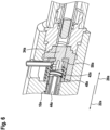
- Fig. 2 shows a schematic representation of a part of the lithotripsy device in a perspective view and Fig. 3 in a sectional view.
- the lithotripsy device has at least one ultrasound generator 74.
- the ultrasound generator 74 is designed to provide ultrasound waves.
- the ultrasound generator 74 is connected to the control unit 56, specifically to the control electronics.
- the ultrasound generator 74 is at least partially arranged in the housing 70. In the present case, the ultrasound generator 74 is arranged entirely in the housing 70.
- the ultrasound generator 74 at least partially forms the proximal section 66 of the lithotripsy device.
- the ultrasonic generator 74 contains at least one ultrasonic actuator 76.
- the ultrasonic generator 74 has a plurality of ultrasonic actuators 76.
- the ultrasonic generator 74 has two ultrasonic actuators 76.
- the ultrasonic actuators 76 are arranged stacked adjacent to one another. For the sake of clarity, only one ultrasonic actuator 76 is provided with a reference symbol in the drawings.
- the ultrasonic actuators 76 are designed at least substantially identically to one another. Only one ultrasonic actuator 76 is described in more detail below. This description also applies to the other ultrasonic actuators 76.
- the ultrasonic actuator 76 is designed as a piezo actuator.
- the ultrasonic actuator 76 is designed in the shape of a cylinder plate. For the sake of clarity, any connection and/or Contacting means and/or insulation of the ultrasonic actuators 76 are not in the Fig. 2 and 3 respectively.
- the lithotripsy device further comprises at least one ultrasonic horn 18.
- the ultrasonic horn 18 receives the ultrasonic waves provided by the ultrasonic generator 74.
- the ultrasonic horn 18 is configured to transmit ultrasonic waves.
- the ultrasonic horn 18 is located on the ultrasonic actuator 76.
- the ultrasonic horn 18 is at least partially arranged within the housing 70.
- the ultrasonic horn 18 at least partially forms the proximal section 66 of the lithotripsy device.
- the ultrasonic horn 18 is arranged at least partially outside the housing 70.
- the ultrasonic horn 18 has the shape of a rotating body. In the present case, the ultrasonic horn 18 has a hollow cylindrical shape.
- the ultrasonic horn 18 is formed at least partially from metal, in particular steel or titanium.
- the ultrasonic generator 74 lies against the ultrasonic horn 18.
- the ultrasonic horn 18 tapers along the first transmission direction 20.
- the ultrasonic horn 18 has a taper.
- the taper is located within the housing 70.
- the taper is free of steps.
- the taper has a continuous profile.
- the taper profile is concave.
- the taper profile is exponential. Alternatively or additionally, the taper could also be step-shaped or catenoidal.
- the ultrasonic horn 18 has a recess 80.
- the recess 80 runs coaxially along a rotation axis of the ultrasonic horn 18.
- the lithotripsy device has at least one sonotrode 10.
- the sonotrode 10 has a main extension 26.
- the sonotrode 10 is arranged at least partially outside the housing 70.
- the sonotrode 10 forms at least a large part of the distal section 68 of the lithotripsy device.
- the sonotrode 10 is tubular.
- the sonotrode 10 is rigid.
- the sonotrode 10 is made at least partially of metal, in particular steel.
- To receive ultrasonic waves, the sonotrode 10 has at least one sonotrode head 12.
- the sonotrode head 12 at least partially forms a proximal end of the sonotrode 10.
- the sonotrode 10 has at least one sonotrode tip 14.
- the sonotrode tip 14 at least partially forms a distal end of the sonotrode 10.
- the sonotrode tip 14 is connected to the sonotrode head 12.
- the sonotrode 10 is arranged at least partially in/on the ultrasonic horn 18.
- the sonotrode 10 is surrounded by the ultrasonic horn 18.
- the ultrasonic horn 18 is arranged coaxially surrounding the sonotrode 10.
- the sonotrode 10 is arranged in the recess 80 of the ultrasonic horn 18.
- the sonotrode 10 has a main extension 26.
- the ultrasonic horn 18 has a main extension 28.
- the main extension 26 of the sonotrode 10 is larger than the main extension 28 of the ultrasonic horn 18.
- the sonotrode 10 and the ultrasonic actuators 76 are arranged relative to one another such that the main extension 28 of the ultrasonic horn 18 lies completely within the main extension 26 of the sonotrode 10.
- the ultrasonic horn 18 is configured to transmit and focus ultrasonic waves at least indirectly onto a sonotrode head 12 of the sonotrode 10 along a first transmission direction 20.
- the first transmission direction 20 corresponds to a proximal direction.
- the sonotrode 10a is connected to the ultrasonic horn 18.
- the sonotrode head 12 is connected to the ultrasonic horn 18.
- the sonotrode 10 and the ultrasonic horn 18 are screwed together.
- the sonotrode can be glued or soldered to the ultrasonic horn.
- the sonotrode 10 is configured to transmit the ultrasonic waves from the sonotrode head 12 to the sonotrode tip 14 along at least one second transmission direction 22, which is different from the first transmission direction 20.
- the second transmission direction 22 corresponds to a distal direction.
- the first transmission direction 20 and the second transmission direction 22 are opposite to each other.
- the sonotrode 10 pierces the ultrasonic horn 18 along the second transmission direction 22.
- the sonotrode 10 protrudes from the ultrasonic horn 18 on the proximal side. Furthermore, the sonotrode 10 protrudes from the ultrasonic waves on the distal side.
- the lithotripsy device is configured to transmit shock pulses to concretions.
- the lithotripsy device comprises a shock pulse unit 32.
- the shock pulse unit 32 comprises at least one projectile 62.
- the projectile 62 is mounted for linear movement. In at least one operating state, the projectile 62 is configured to at least indirectly act on the sonotrode 10 and/or the ultrasonic horn 18. In the present case, the projectile 62 acts on the sonotrode 10 indirectly.
- the shock pulse unit 32 comprises at least one guide channel 82.
- the lithotripsy device comprises a guide tube 84 which delimits the guide channel 82.
- the projectile could be movably mounted within the sonotrode or the ultrasonic horn.
- the drive device 64 is coupled to the shock pulse unit 32.
- the shock pulse unit 32 is connected to the guide channel 82.
- a connecting piece is arranged on the guide tube 84.
- the drive device 64a is connected to the connecting piece via a hose.
- the drive device 64a transmits compressed air pulses to the guide channel 82. whereby the projectile 62a arranged in the guide channel 82 is accelerated.
- the drive device 64a accelerates the projectile 62a within the guide channel 82.
- the lithotripsy device has a coupling unit 30 (see Fig. 4 ).
- the coupling unit 30 is configured to couple the sonotrode 10 to the shock pulse unit 32.
- the coupling unit 30 has at least one transmission element 34.
- the transmission element 34 has at least a first active surface 36.
- the first active surface 36 is configured to receive a pulse. In an operating state, the projectile 62 strikes the active surface 36.
- the transmission element 34 has at least a second active surface 38.
- the second active surface 38 lies opposite the first active surface 36.
- the second active surface 38 is configured to at least indirectly transmit the received pulse to the sonotrode 10 along the second transmission direction 22.
- the transmission element 34 is mounted in a floating manner.
- the transmission element 34 is arranged with play between the sonotrode 14 and the projectile 62. It is conceivable that the transmission element could also be formed integrally with the sonotrode 10.
- the coupling unit 30 has a quick connector 40.
- the quick connector 40 is designed to establish and detach a mechanical connection between the shock pulse unit 32 and the sonotrode 10.
- the quick connector 40 is designed to establish a connection that can be released without the use of tools and without causing damage.
- the connection is a force-locking and/or positive-locking connection.
- the quick connector 40 forms the screw closure.
- other types of quick connectors are also conceivable, such as a bayonet closure or the like.
- the lithotripsy device has a fluid unit 42.
- the fluid unit 42 is configured to provide a fluid for rinsing and/or to discharge a fluid.
- the fluid unit 42 has at least one fluid channel 44.
- the fluid channel 44 is at least partially formed by the sonotrode 10.
- the sonotrode 10 has an axial recess which partially forms the fluid channel 44.
- the fluid channel 44 is at least partially formed by the coupling unit 30.
- the transmission element 34 has an axial recess which partially forms the fluid channel 44.
- the fluid channel 44 has at least one bend 46.
- the bend 46 of the fluid channel 44 is arranged in the region of the coupling unit 30.
- the bend 46 is integrated into the transmission element 34.
- the transmission element 34 has at least one radial opening. The radial opening establishes a connection to the axial recess of the transmission element 34.
- the lithotripsy device has at least one bearing unit 48.
- the bearing unit 48 is designed to move the sonotrode 10 along the first and/or second
- the bearing unit 48 is designed as a sliding bearing.
- the bearing unit 48 has at least one sealing element 50.
- the bearing unit 48 is formed by adjacent surfaces of the sonotrode 10 and/or the transmission element 34, as well as a guide channel 82 embedded in the housing 70.
- Figure 5 shows a schematic flow chart of an exemplary method for operating the lithotripsy device.
- the operation is an extracorporeal test operation.
- the method comprises a method step 100.
- the ultrasonic generator 74 is activated.
- the ultrasonic generator 74 generates ultrasonic waves.
- the ultrasonic waves are transmitted and focused by the ultrasonic horn 18 along the first transmission direction 20.
- the ultrasonic waves are received by the sonotrode head 12. From the sonotrode head 12, the ultrasonic waves are transmitted along a second transmission direction 22 to the sonotrode tip 14.
- the sonotrode tip 14 transmits the ultrasonic waves to any concretions, which can be destroyed as a result.
- the method comprises a method step 102.
- the shock pulse unit 32 is activated.
- the drive device 64 pneumatically accelerates the projectile 62.
- the projectile 62 strikes the transmission element 34. This largely stops the movement of the projectile 62 and transmits a shock pulse from the projectile 62 to the transmission element 34.
- the transmission element 34 is in contact with the sonotrode 10
- the sonotrode in turn transmits the shock pulse to the sonotrode head 12.
- the shock pulse is transmitted along the second transmission direction 22 from the sonotrode head 12 to the sonotrode tip 14.
- the sonotrode tip 14 in turn transmits the shock pulse to any concretions, which can be destroyed as a result.
- Process steps 100 and 102 can be performed in any order, either alternately or simultaneously. Especially when process steps 100 and 102 are performed simultaneously, a combined operation can be achieved, in which any concretions can be subjected to ultrasonic waves and shock pulses simultaneously.
- the lithotripsy device has at least one bearing unit 48a.
- the bearing unit 48a is configured to movably and floatingly support a sonotrode 10a of the lithotripsy device along a first and/or a second transmission direction 20a, 22a.
- the bearing unit 48a has at least one sealing element 50a, which at least partially delimits a fluid channel 44a of a fluid unit 42a of the lithotripsy device.
- the sealing element 50a is connected to the sonotrode 10a and a transmission element 34a of a coupling unit 30a of the lithotripsy device.
- the sealing element 50a is designed as a bellows.
- the sealing element 50a is connected to a sonotrode 10a and the transmission element 34a in a force-fitting and/or form-fitting manner.
Landscapes
- Health & Medical Sciences (AREA)
- Surgery (AREA)
- Engineering & Computer Science (AREA)
- Life Sciences & Earth Sciences (AREA)
- Biomedical Technology (AREA)
- Nuclear Medicine, Radiotherapy & Molecular Imaging (AREA)
- Vascular Medicine (AREA)
- Orthopedic Medicine & Surgery (AREA)
- Mechanical Engineering (AREA)
- Heart & Thoracic Surgery (AREA)
- Medical Informatics (AREA)
- Molecular Biology (AREA)
- Animal Behavior & Ethology (AREA)
- General Health & Medical Sciences (AREA)
- Public Health (AREA)
- Veterinary Medicine (AREA)
- Surgical Instruments (AREA)
Claims (19)
- Dispositif de lithotripsie, en particulier dispositif de lithotripsie intracorporelle, comportant au moins une sonotrode (10a), laquelle comprend au moins une tête de sonotrode (12) pour la réception d'ondes ultrasonores, et au moins une pointe de sonotrode (14), laquelle est reliée à la tête de sonotrode (12), pour la sollicitation de concrétions, et comportant une unité à ultrasons (16) qui présente au moins un cornet à ultrasons (18), dans lequel la sonotrode (10a) est configurée pour transmettre les ondes ultrasonores de la tête de sonotrode (12) à la pointe de sonotrode (14), le long d'au moins une seconde direction de transmission (22, 22a), caractérisé en ce que le cornet à ultrasons (18) se rétrécit le long d'une première direction de transmission (20, 20a) et est configuré pour transmettre et focaliser des ondes ultrasonores au moins indirectement sur la tête de sonotrode (12) le long de la première direction de transmission (20, 20a), dans lequel la seconde direction de transmission (22, 22a) est différente de la première direction de transmission (20, 20a).
- Dispositif de lithotripsie selon la revendication 1, caractérisé en ce que la première direction de transmission (20, 20a) et la seconde direction de transmission (22, 22a) sont opposées l'une à l'autre.
- Dispositif de lithotripsie selon la revendication 1 ou 2, caractérisé en ce que le cornet à ultrasons (18) est disposé de manière à entourer de manière coaxiale la sonotrode (10a).
- Dispositif de lithotripsie selon l'une des revendications précédentes, caractérisé en ce que la sonotrode (10a) perce le cornet à ultrasons (18) le long de la seconde direction de transmission (22, 22a).
- Dispositif de lithotripsie selon l'une des revendications précédentes, caractérisé en ce qu'une extension principale (26) de la sonotrode (10a) est supérieure à une extension principale (28) du cornet à ultrasons (18).
- Dispositif de lithotripsie selon l'une des revendications précédentes, caractérisé par une unité de couplage (30a) qui, afin de solliciter la sonotrode (10a), est configurée pour coupler la sonotrode (10a) à une unité d'impulsion d'impact (32).
- Dispositif de lithotripsie selon la revendication 6, caractérisé en ce que l'unité de couplage (30a) présente au moins un élément de
transmission (34a) qui présente au moins une première surface active (36) qui est configurée pour recevoir une impulsion, et au moins une seconde surface active (38) qui est opposée à la première surface active (36) et qui est configurée pour transmettre au moins indirectement l'impulsion reçue à la sonotrode (10a) le long de la seconde direction de transmission (22, 22a). - Dispositif de lithotripsie selon la revendication 6 ou 7, caractérisé en ce que l'unité de couplage (30a) comprend une liaison rapide (40) qui est conçue pour une liaison mécanique réalisable et amovible de l'unité d'impulsion d'impact (32) avec la sonotrode (10a).
- Dispositif de lithotripsie selon l'une des revendications précédentes, caractérisé par une unité fluidique (42a) qui comprend au moins un canal fluidique (44a) qui est réalisé au moins partiellement par la sonotrode (10a) et présente au moins un coude (46).
- Dispositif de lithotripsie selon l'une des revendications 6 à 8 et selon la revendication 9, caractérisé en ce que le canal fluidique (44a) est réalisé au moins partiellement par l'unité de couplage (30a).
- Dispositif de lithotripsie selon la revendication 9 ou 10,
caractérisé en ce que le coude (46) du canal fluidique (44a) est disposé dans la zone de l'unité de couplage (30a). - Dispositif de lithotripsie selon l'une des revendications 7 ou 8 et selon l'une des revendications 9 à 11, caractérisé en ce que le coude (46) est intégré à l'élément de transmission (34a).
- Dispositif de lithotripsie selon l'une des revendications précédentes, caractérisé par au moins une unité de soutien (48a) qui est conçue pour soutenir de manière flottante la sonotrode (10a) de manière à permettre son déplacement le long de la première et/ou de la seconde direction de transmission (20, 20a, 22, 22a).
- Dispositif de lithotripsie selon l'une des revendications 9 à 12 et selon la revendication 13, caractérisé en ce que l'unité de soutien (48a) comprend au moins un élément d'étanchéité (50a) qui délimite au moins partiellement le canal fluidique (44a).
- Dispositif de lithotripsie selon l'une des revendications 7 ou 8 et selon la revendication 14, caractérisé en ce que l'élément d'étanchéité (50a) est relié à la sonotrode (10a) et à l'élément de transmission (34a).
- Dispositif de lithotripsie au moins selon la revendication 14 ou 15, caractérisé en ce que l'élément d'étanchéité (50a) est réalisé sous forme de soufflet.
- Lithotripteur (52), en particulier lithotripteur intracorporel, comportant au moins un dispositif de lithotripsie selon l'une des revendications précédentes.
- Système de lithotripsie (54) comportant au moins un lithotripteur (52) selon la revendication 17 et comportant au moins un appareil de commande (56) qui est configuré pour commander le lithotripteur (52).
- Procédé permettant le fonctionnement d'essai extracorporel d'un dispositif de lithotripsie, en particulier d'un dispositif de lithotripsie selon l'une des revendications 1 à 16, dans lequel des ondes ultrasonores sont reçues par une tête de sonotrode (12) d'une sonotrode (10a) et des concrétions sont soumises à au moins une pointe de sonotrode (14) de la sonotrode (10a), laquelle est reliée à la tête de sonotrode (12), et les ondes ultrasonores sont fournies par une unité à ultrasons (16) qui présente au moins un cornet à ultrasons (18), dans lequel le cornet à ultrasons (18) transmet et focalise les ondes ultrasonores au moins indirectement sur la tête de sonotrode (12) le long d'une première direction de transmission (20, 20a) et la sonotrode (10a) transmet les ondes ultrasonores de la tête de sonotrode (12) à la pointe de sonotrode (14) le long d'au moins une seconde direction de transmission (22, 22a), laquelle est différente de la première direction de transmission (20, 20a), dans lequel le cornet à ultrasons (18) se rétrécit le long de la première direction de transmission (20, 20a).
Applications Claiming Priority (2)
| Application Number | Priority Date | Filing Date | Title |
|---|---|---|---|
| DE102020117713.5A DE102020117713B4 (de) | 2020-07-06 | 2020-07-06 | Lithotripsievorrichtung und Verfahren zum Betrieb einer Lithotripsievorrichtung |
| PCT/EP2021/068510 WO2022008440A1 (fr) | 2020-07-06 | 2021-07-05 | Dispositif de lithotripsie et procédé de fonctionnement d'un dispositif de lithotripsie |
Publications (2)
| Publication Number | Publication Date |
|---|---|
| EP4175567A1 EP4175567A1 (fr) | 2023-05-10 |
| EP4175567B1 true EP4175567B1 (fr) | 2025-04-02 |
Family
ID=77104014
Family Applications (1)
| Application Number | Title | Priority Date | Filing Date |
|---|---|---|---|
| EP21746651.5A Active EP4175567B1 (fr) | 2020-07-06 | 2021-07-05 | Dispositif de lithotripsie et procédé de fonctionnement en mode test d'un dispositif de lithotripsie |
Country Status (3)
| Country | Link |
|---|---|
| EP (1) | EP4175567B1 (fr) |
| DE (1) | DE102020117713B4 (fr) |
| WO (1) | WO2022008440A1 (fr) |
Families Citing this family (26)
| Publication number | Priority date | Publication date | Assignee | Title |
|---|---|---|---|---|
| US11819229B2 (en) | 2019-06-19 | 2023-11-21 | Boston Scientific Scimed, Inc. | Balloon surface photoacoustic pressure wave generation to disrupt vascular lesions |
| US12402946B2 (en) | 2019-06-19 | 2025-09-02 | Boston Scientific Scimed, Inc. | Breakdown of laser pulse energy for breakup of vascular calcium |
| US11717139B2 (en) | 2019-06-19 | 2023-08-08 | Bolt Medical, Inc. | Plasma creation via nonaqueous optical breakdown of laser pulse energy for breakup of vascular calcium |
| US11660427B2 (en) | 2019-06-24 | 2023-05-30 | Boston Scientific Scimed, Inc. | Superheating system for inertial impulse generation to disrupt vascular lesions |
| US20200406010A1 (en) | 2019-06-26 | 2020-12-31 | Boston Scientific Scimed, Inc. | Side light direction plasma system to disrupt vascular lesions |
| US11583339B2 (en) | 2019-10-31 | 2023-02-21 | Bolt Medical, Inc. | Asymmetrical balloon for intravascular lithotripsy device and method |
| US12102384B2 (en) | 2019-11-13 | 2024-10-01 | Bolt Medical, Inc. | Dynamic intravascular lithotripsy device with movable energy guide |
| US12274497B2 (en) | 2019-12-18 | 2025-04-15 | Bolt Medical, Inc. | Multiplexer for laser-driven intravascular lithotripsy device |
| US12446961B2 (en) | 2020-02-10 | 2025-10-21 | Bolt Medical, Inc. | System and method for pressure monitoring within a catheter system |
| US11672599B2 (en) | 2020-03-09 | 2023-06-13 | Bolt Medical, Inc. | Acoustic performance monitoring system and method within intravascular lithotripsy device |
| US12611253B2 (en) | 2020-03-18 | 2026-04-28 | Boston Scientific Scimed, Inc. | Optical analyzer assembly and method for intravascular lithotripsy device |
| US11707323B2 (en) | 2020-04-03 | 2023-07-25 | Bolt Medical, Inc. | Electrical analyzer assembly for intravascular lithotripsy device |
| US20210353359A1 (en) | 2020-05-12 | 2021-11-18 | Bolt Medical, Inc. | Active alignment system and method for optimizing optical coupling of multiplexer for laser-driven intravascular lithotripsy device |
| US12295654B2 (en) | 2020-06-03 | 2025-05-13 | Boston Scientific Scimed, Inc. | System and method for maintaining balloon integrity within intravascular lithotripsy device with plasma generator |
| US12207870B2 (en) | 2020-06-15 | 2025-01-28 | Boston Scientific Scimed, Inc. | Spectroscopic tissue identification for balloon intravascular lithotripsy guidance |
| US12016610B2 (en) | 2020-12-11 | 2024-06-25 | Bolt Medical, Inc. | Catheter system for valvuloplasty procedure |
| WO2022154954A1 (fr) | 2021-01-12 | 2022-07-21 | Bolt Medical, Inc. | Ensemble ballonnet pour système de cathéter de valvuloplastie |
| US11672585B2 (en) | 2021-01-12 | 2023-06-13 | Bolt Medical, Inc. | Balloon assembly for valvuloplasty catheter system |
| US11648057B2 (en) | 2021-05-10 | 2023-05-16 | Bolt Medical, Inc. | Optical analyzer assembly with safety shutdown system for intravascular lithotripsy device |
| US11806075B2 (en) | 2021-06-07 | 2023-11-07 | Bolt Medical, Inc. | Active alignment system and method for laser optical coupling |
| DE102021131670A1 (de) | 2021-12-01 | 2023-06-01 | Karl Storz Se & Co. Kg | Lithotripsievorrichtung zum Zertrümmern von Körpersteinen und Verfahren zum Einstellen einer Beschleunigungsstrecke eines Beschleunigungsrohres einer Lithotripsievorrichtung |
| US11839391B2 (en) | 2021-12-14 | 2023-12-12 | Bolt Medical, Inc. | Optical emitter housing assembly for intravascular lithotripsy device |
| DE102022109138B4 (de) | 2022-04-13 | 2024-06-20 | Karl Storz Se & Co. Kg | Lithotripsievorrichtung zum Zertrümmern von Körpersteinen mit einer Steuerhülse und Verfahren zum Beschleunigen eines Projektils einer Lithotripsievorrichtung |
| DE102022109140B4 (de) | 2022-04-13 | 2024-06-20 | Karl Storz Se & Co. Kg | Lithotripsievorrichtung zum Zertrümmern von Körpersteinen mit einem axial bewegbaren Beschleunigungsrohr und Verfahren zum Beschleunigen eines Projektils einer Lithotripsievorrichtung |
| DE102022126989A1 (de) * | 2022-10-14 | 2024-04-25 | Karl Storz Se & Co. Kg | Medizinisches Instrument zum Behandeln eines Körpers mit einer Druckentlastungseinrichtung |
| DE102022129228A1 (de) * | 2022-11-04 | 2024-05-08 | Karl Storz Se & Co. Kg | Lithotripsievorrichtung zum Zertrümmern von Körpersteinen mit einem Hebelelement und Nachrüstsatz zum Nachrüsten einer bestehenden Lithotripsievorrichtung |
Citations (20)
| Publication number | Priority date | Publication date | Assignee | Title |
|---|---|---|---|---|
| DE2209860A1 (de) | 1971-03-04 | 1972-09-14 | Borg Warner | Faltenbalgdichtung |
| JPS62127041A (ja) | 1985-11-28 | 1987-06-09 | オリンパス光学工業株式会社 | 超音波砕石プロ−ブ |
| DE3707403A1 (de) | 1986-03-11 | 1987-09-17 | Olympus Optical Co | Medizinisches resektionsgeraet |
| DE4042435C2 (de) | 1990-02-02 | 1994-02-17 | Olympus Optical Co | Ultraschallbehandlungsvorrichtung |
| DE19507478C1 (de) | 1995-03-03 | 1996-05-15 | Siemens Ag | Therapiegerät zur Behandlung mit fokussiertem Ultraschall |
| WO2000072766A1 (fr) | 1999-05-27 | 2000-12-07 | Angiosonics Inc. | Appareil de transmission d'ultrasons avec pointe |
| EP1163882A1 (fr) | 2000-06-15 | 2001-12-19 | Ferton Holding SA | Lithotripteur intracorporel pour l'enlèvement de calculs |
| EP1163883A1 (fr) | 2000-06-15 | 2001-12-19 | Ferton Holding SA | Lithotriteur intracorporelle pour évacuer des concrétions calcaires |
| US20020007200A1 (en) | 2000-05-03 | 2002-01-17 | Kai Desinger | Manually actuable ultrasonic disintegrator for breaking up or removing human or animal tissue |
| US20020010478A1 (en) | 2000-06-15 | 2002-01-24 | Ferton Holding S.A. | Device for removal of calculi |
| DE20022925U1 (de) | 2000-06-15 | 2002-10-02 | Ferton Holding S.A., Delemont | Vorrichtung zur Entfernung von Körpersteinen unter Verwendung eines intrakorporalen Lithotripters |
| US20040138594A1 (en) | 2002-12-04 | 2004-07-15 | Naomi Sekino | Endoscopic lithotripsy apparatus and lithotripsy method of treatment object using the apparatus |
| US6875220B2 (en) | 2002-12-30 | 2005-04-05 | Cybersonics, Inc. | Dual probe |
| DE102014202571A1 (de) | 2014-02-12 | 2015-08-13 | Robert Bosch Gmbh | Pumpe zur Förderung eines Fluids |
| EP2913015A1 (fr) | 2012-10-25 | 2015-09-02 | Olympus Corporation | Sonde ultrasonore |
| EP3165188A1 (fr) | 2014-07-02 | 2017-05-10 | Olympus Corporation | Sonde à ultrasons et outil de traitement à ultrasons |
| JP2018042185A (ja) | 2016-09-09 | 2018-03-15 | マイクロソニック株式会社 | 超音波伝送線路及び超音波利用装置 |
| DE202018006201U1 (de) | 2018-01-19 | 2019-07-19 | Ferton Holding S.A. | System zum Zertrümmern und/oder Entfernen von Körpersteinen und Adapterelement |
| WO2019141822A1 (fr) | 2018-01-19 | 2019-07-25 | Ferton Holding S.A. | Dispositif et procédé pour la désintégration d'une pierre corporelle |
| US20200107848A1 (en) | 2018-10-05 | 2020-04-09 | Kogent Surgical, LLC | Ultrasonic surgical handpiece with torsional transducer |
-
2020
- 2020-07-06 DE DE102020117713.5A patent/DE102020117713B4/de active Active
-
2021
- 2021-07-05 EP EP21746651.5A patent/EP4175567B1/fr active Active
- 2021-07-05 WO PCT/EP2021/068510 patent/WO2022008440A1/fr not_active Ceased
Patent Citations (20)
| Publication number | Priority date | Publication date | Assignee | Title |
|---|---|---|---|---|
| DE2209860A1 (de) | 1971-03-04 | 1972-09-14 | Borg Warner | Faltenbalgdichtung |
| JPS62127041A (ja) | 1985-11-28 | 1987-06-09 | オリンパス光学工業株式会社 | 超音波砕石プロ−ブ |
| DE3707403A1 (de) | 1986-03-11 | 1987-09-17 | Olympus Optical Co | Medizinisches resektionsgeraet |
| DE4042435C2 (de) | 1990-02-02 | 1994-02-17 | Olympus Optical Co | Ultraschallbehandlungsvorrichtung |
| DE19507478C1 (de) | 1995-03-03 | 1996-05-15 | Siemens Ag | Therapiegerät zur Behandlung mit fokussiertem Ultraschall |
| WO2000072766A1 (fr) | 1999-05-27 | 2000-12-07 | Angiosonics Inc. | Appareil de transmission d'ultrasons avec pointe |
| US20020007200A1 (en) | 2000-05-03 | 2002-01-17 | Kai Desinger | Manually actuable ultrasonic disintegrator for breaking up or removing human or animal tissue |
| DE20022925U1 (de) | 2000-06-15 | 2002-10-02 | Ferton Holding S.A., Delemont | Vorrichtung zur Entfernung von Körpersteinen unter Verwendung eines intrakorporalen Lithotripters |
| EP1163883A1 (fr) | 2000-06-15 | 2001-12-19 | Ferton Holding SA | Lithotriteur intracorporelle pour évacuer des concrétions calcaires |
| US20020010478A1 (en) | 2000-06-15 | 2002-01-24 | Ferton Holding S.A. | Device for removal of calculi |
| EP1163882A1 (fr) | 2000-06-15 | 2001-12-19 | Ferton Holding SA | Lithotripteur intracorporel pour l'enlèvement de calculs |
| US20040138594A1 (en) | 2002-12-04 | 2004-07-15 | Naomi Sekino | Endoscopic lithotripsy apparatus and lithotripsy method of treatment object using the apparatus |
| US6875220B2 (en) | 2002-12-30 | 2005-04-05 | Cybersonics, Inc. | Dual probe |
| EP2913015A1 (fr) | 2012-10-25 | 2015-09-02 | Olympus Corporation | Sonde ultrasonore |
| DE102014202571A1 (de) | 2014-02-12 | 2015-08-13 | Robert Bosch Gmbh | Pumpe zur Förderung eines Fluids |
| EP3165188A1 (fr) | 2014-07-02 | 2017-05-10 | Olympus Corporation | Sonde à ultrasons et outil de traitement à ultrasons |
| JP2018042185A (ja) | 2016-09-09 | 2018-03-15 | マイクロソニック株式会社 | 超音波伝送線路及び超音波利用装置 |
| DE202018006201U1 (de) | 2018-01-19 | 2019-07-19 | Ferton Holding S.A. | System zum Zertrümmern und/oder Entfernen von Körpersteinen und Adapterelement |
| WO2019141822A1 (fr) | 2018-01-19 | 2019-07-25 | Ferton Holding S.A. | Dispositif et procédé pour la désintégration d'une pierre corporelle |
| US20200107848A1 (en) | 2018-10-05 | 2020-04-09 | Kogent Surgical, LLC | Ultrasonic surgical handpiece with torsional transducer |
Non-Patent Citations (1)
| Title |
|---|
| INTERNATIONALER VORLÄUFIGER BERICHT ÜBER DIE PATENTIERBARKEIT (IPRP) ZUR PCT-ANMELDUNG WO 2022/008440 A1 |
Also Published As
| Publication number | Publication date |
|---|---|
| DE102020117713A1 (de) | 2022-01-13 |
| WO2022008440A1 (fr) | 2022-01-13 |
| DE102020117713B4 (de) | 2024-11-07 |
| EP4175567A1 (fr) | 2023-05-10 |
Similar Documents
| Publication | Publication Date | Title |
|---|---|---|
| EP4175567B1 (fr) | Dispositif de lithotripsie et procédé de fonctionnement en mode test d'un dispositif de lithotripsie | |
| EP1163882B1 (fr) | Lithotripteur intracorporel pour l'enlèvement de calculs | |
| DE3932966C1 (fr) | ||
| EP3733313B1 (fr) | Dispositif de lithotripsie et procédé d'essai destiné au fonctionnement d'un dispositif de lithotripsie | |
| EP1163883B1 (fr) | Lithotriteur intracorporelle pour évacuer des concrétions calcaires | |
| DE69500182T2 (de) | Ultraschallperkussionsgerät | |
| DE4042435C2 (de) | Ultraschallbehandlungsvorrichtung | |
| DE102020134602B4 (de) | Lithotripsievorrichtung, Lithotripsiesystem und Verfahren zum Betreiben einer Lithotripsievorrichtung | |
| EP1163884B1 (fr) | Lithotripteur intracorporelle pour évacuer des concrétions calcaires | |
| EP3875045B1 (fr) | Dispositif de lithotripsie | |
| DE102022109138B4 (de) | Lithotripsievorrichtung zum Zertrümmern von Körpersteinen mit einer Steuerhülse und Verfahren zum Beschleunigen eines Projektils einer Lithotripsievorrichtung | |
| EP4422523A1 (fr) | Dispositif de lithotritie pour détruire les calculs et procédé de réglage de la trajectoire d'accélération d'un tube d'accélération d'un dispositif de lithotritie | |
| DE3814743C2 (de) | Einrichtung zur Auflösung von Konkrementen in einer Körperhöhle | |
| EP4140417B1 (fr) | Dispositif de lithotripsie | |
| EP4419021A1 (fr) | Sonde d'application pour fragmentation de calculs pour un dispositif de lithotritie, dispositif de lithotritie, système de lithotritie et méthode pour faire fonctionner un dispositif de lithotritie | |
| EP4385429B1 (fr) | Dispositif de maintien pour un dispositif de lithotripsie destiné à la destruction de calculs corporels et dispositif de lithotripsie | |
| EP4385430B1 (fr) | Dispositif de maintien pour un dispositif de lithotripsie et dispositif de lithotripsie destiné à la destruction de calculs corporels | |
| DE102022126984B4 (de) | Lithotripsievorrichtung zum Zertrümmern von Körpersteinen mit einem Gegenprojektil und Verfahren zum Beschleunigen eines Projektils einer Lithotripsievorrichtung | |
| DE102022126988B3 (de) | Kopfvorrichtung einer Lithotripsievorrichtung, Lithotripsievorrichtung und Nachrüstsatz zum Nachrüsten einer bestehenden Lithotripsievorrichtung | |
| DE102022126994A1 (de) | Kopfvorrichtung einer Lithotripsievorrichtung, Lithotripsievorrichtung zum Zertrümmern von Körpersteinen und Nachrüstsatz | |
| DE102022126987A1 (de) | Federeinrichtung zum Zwischenspeichern einer Bewegungsenergie und/oder Verlängern einer Stoßdauer eines Projektils einer Lithotripsievorrichtung, Lithotripsievorrichtung, Nachrüstsatz und Verfahren zum Aufprägen einer Verformungswelle auf eine Sonotrode | |
| DE102008051174A1 (de) | Vorrichtung zum Einleiten von Stosswellen in einen lebenden Körper und deren Verwendung | |
| DE20023753U1 (de) | Medizinisches Instrument zur Behandlung von biologischem Gewebe | |
| DE2053982B2 (de) | Vorrichtung zur Zertrümmerung von Blasen-, Urether- und Nierenbeckensteinen |
Legal Events
| Date | Code | Title | Description |
|---|---|---|---|
| STAA | Information on the status of an ep patent application or granted ep patent |
Free format text: STATUS: UNKNOWN |
|
| STAA | Information on the status of an ep patent application or granted ep patent |
Free format text: STATUS: THE INTERNATIONAL PUBLICATION HAS BEEN MADE |
|
| PUAI | Public reference made under article 153(3) epc to a published international application that has entered the european phase |
Free format text: ORIGINAL CODE: 0009012 |
|
| STAA | Information on the status of an ep patent application or granted ep patent |
Free format text: STATUS: REQUEST FOR EXAMINATION WAS MADE |
|
| 17P | Request for examination filed |
Effective date: 20230117 |
|
| AK | Designated contracting states |
Kind code of ref document: A1 Designated state(s): AL AT BE BG CH CY CZ DE DK EE ES FI FR GB GR HR HU IE IS IT LI LT LU LV MC MK MT NL NO PL PT RO RS SE SI SK SM TR |
|
| DAV | Request for validation of the european patent (deleted) | ||
| DAX | Request for extension of the european patent (deleted) | ||
| GRAP | Despatch of communication of intention to grant a patent |
Free format text: ORIGINAL CODE: EPIDOSNIGR1 |
|
| STAA | Information on the status of an ep patent application or granted ep patent |
Free format text: STATUS: GRANT OF PATENT IS INTENDED |
|
| INTG | Intention to grant announced |
Effective date: 20241126 |
|
| GRAS | Grant fee paid |
Free format text: ORIGINAL CODE: EPIDOSNIGR3 |
|
| GRAA | (expected) grant |
Free format text: ORIGINAL CODE: 0009210 |
|
| STAA | Information on the status of an ep patent application or granted ep patent |
Free format text: STATUS: THE PATENT HAS BEEN GRANTED |
|
| AK | Designated contracting states |
Kind code of ref document: B1 Designated state(s): AL AT BE BG CH CY CZ DE DK EE ES FI FR GB GR HR HU IE IS IT LI LT LU LV MC MK MT NL NO PL PT RO RS SE SI SK SM TR |
|
| REG | Reference to a national code |
Ref country code: GB Ref legal event code: FG4D Free format text: NOT ENGLISH |
|
| REG | Reference to a national code |
Ref country code: CH Ref legal event code: EP |
|
| REG | Reference to a national code |
Ref country code: DE Ref legal event code: R096 Ref document number: 502021007114 Country of ref document: DE |
|
| REG | Reference to a national code |
Ref country code: IE Ref legal event code: FG4D Free format text: LANGUAGE OF EP DOCUMENT: GERMAN |
|
| REG | Reference to a national code |
Ref country code: NL Ref legal event code: MP Effective date: 20250402 |
|
| REG | Reference to a national code |
Ref country code: DE Ref legal event code: R026 Ref document number: 502021007114 Country of ref document: DE |
|
| PLBI | Opposition filed |
Free format text: ORIGINAL CODE: 0009260 |
|
| PG25 | Lapsed in a contracting state [announced via postgrant information from national office to epo] |
Ref country code: NL Free format text: LAPSE BECAUSE OF FAILURE TO SUBMIT A TRANSLATION OF THE DESCRIPTION OR TO PAY THE FEE WITHIN THE PRESCRIBED TIME-LIMIT Effective date: 20250402 |
|
| 26 | Opposition filed |
Opponent name: E.M.S. ELECTRO MEDICAL SYSTEMS S.A. Effective date: 20250807 |
|
| PG25 | Lapsed in a contracting state [announced via postgrant information from national office to epo] |
Ref country code: FI Free format text: LAPSE BECAUSE OF FAILURE TO SUBMIT A TRANSLATION OF THE DESCRIPTION OR TO PAY THE FEE WITHIN THE PRESCRIBED TIME-LIMIT Effective date: 20250402 Ref country code: ES Free format text: LAPSE BECAUSE OF FAILURE TO SUBMIT A TRANSLATION OF THE DESCRIPTION OR TO PAY THE FEE WITHIN THE PRESCRIBED TIME-LIMIT Effective date: 20250402 Ref country code: PT Free format text: LAPSE BECAUSE OF FAILURE TO SUBMIT A TRANSLATION OF THE DESCRIPTION OR TO PAY THE FEE WITHIN THE PRESCRIBED TIME-LIMIT Effective date: 20250804 |
|
| PGFP | Annual fee paid to national office [announced via postgrant information from national office to epo] |
Ref country code: DE Payment date: 20250728 Year of fee payment: 5 |
|
| REG | Reference to a national code |
Ref country code: LT Ref legal event code: MG9D |
|
| PG25 | Lapsed in a contracting state [announced via postgrant information from national office to epo] |
Ref country code: NO Free format text: LAPSE BECAUSE OF FAILURE TO SUBMIT A TRANSLATION OF THE DESCRIPTION OR TO PAY THE FEE WITHIN THE PRESCRIBED TIME-LIMIT Effective date: 20250702 Ref country code: GR Free format text: LAPSE BECAUSE OF FAILURE TO SUBMIT A TRANSLATION OF THE DESCRIPTION OR TO PAY THE FEE WITHIN THE PRESCRIBED TIME-LIMIT Effective date: 20250703 |
|
| PG25 | Lapsed in a contracting state [announced via postgrant information from national office to epo] |
Ref country code: PL Free format text: LAPSE BECAUSE OF FAILURE TO SUBMIT A TRANSLATION OF THE DESCRIPTION OR TO PAY THE FEE WITHIN THE PRESCRIBED TIME-LIMIT Effective date: 20250402 |
|
| PGFP | Annual fee paid to national office [announced via postgrant information from national office to epo] |
Ref country code: IT Payment date: 20250721 Year of fee payment: 5 |
|
| PG25 | Lapsed in a contracting state [announced via postgrant information from national office to epo] |
Ref country code: BG Free format text: LAPSE BECAUSE OF FAILURE TO SUBMIT A TRANSLATION OF THE DESCRIPTION OR TO PAY THE FEE WITHIN THE PRESCRIBED TIME-LIMIT Effective date: 20250402 |
|
| PGFP | Annual fee paid to national office [announced via postgrant information from national office to epo] |
Ref country code: GB Payment date: 20250722 Year of fee payment: 5 |
|
| PG25 | Lapsed in a contracting state [announced via postgrant information from national office to epo] |
Ref country code: HR Free format text: LAPSE BECAUSE OF FAILURE TO SUBMIT A TRANSLATION OF THE DESCRIPTION OR TO PAY THE FEE WITHIN THE PRESCRIBED TIME-LIMIT Effective date: 20250402 |
|
| PGFP | Annual fee paid to national office [announced via postgrant information from national office to epo] |
Ref country code: FR Payment date: 20250725 Year of fee payment: 5 Ref country code: AT Payment date: 20251020 Year of fee payment: 5 |
|
| PGFP | Annual fee paid to national office [announced via postgrant information from national office to epo] |
Ref country code: CH Payment date: 20250801 Year of fee payment: 5 |
|
| PG25 | Lapsed in a contracting state [announced via postgrant information from national office to epo] |
Ref country code: RS Free format text: LAPSE BECAUSE OF FAILURE TO SUBMIT A TRANSLATION OF THE DESCRIPTION OR TO PAY THE FEE WITHIN THE PRESCRIBED TIME-LIMIT Effective date: 20250702 |
|
| PG25 | Lapsed in a contracting state [announced via postgrant information from national office to epo] |
Ref country code: IS Free format text: LAPSE BECAUSE OF FAILURE TO SUBMIT A TRANSLATION OF THE DESCRIPTION OR TO PAY THE FEE WITHIN THE PRESCRIBED TIME-LIMIT Effective date: 20250802 |
|
| PG25 | Lapsed in a contracting state [announced via postgrant information from national office to epo] |
Ref country code: LV Free format text: LAPSE BECAUSE OF FAILURE TO SUBMIT A TRANSLATION OF THE DESCRIPTION OR TO PAY THE FEE WITHIN THE PRESCRIBED TIME-LIMIT Effective date: 20250402 |
|
| PG25 | Lapsed in a contracting state [announced via postgrant information from national office to epo] |
Ref country code: DK Free format text: LAPSE BECAUSE OF FAILURE TO SUBMIT A TRANSLATION OF THE DESCRIPTION OR TO PAY THE FEE WITHIN THE PRESCRIBED TIME-LIMIT Effective date: 20250402 Ref country code: SM Free format text: LAPSE BECAUSE OF FAILURE TO SUBMIT A TRANSLATION OF THE DESCRIPTION OR TO PAY THE FEE WITHIN THE PRESCRIBED TIME-LIMIT Effective date: 20250402 |
|
| PG25 | Lapsed in a contracting state [announced via postgrant information from national office to epo] |
Ref country code: CZ Free format text: LAPSE BECAUSE OF FAILURE TO SUBMIT A TRANSLATION OF THE DESCRIPTION OR TO PAY THE FEE WITHIN THE PRESCRIBED TIME-LIMIT Effective date: 20250402 |
|
| PLAX | Notice of opposition and request to file observation + time limit sent |
Free format text: ORIGINAL CODE: EPIDOSNOBS2 |
|
| PG25 | Lapsed in a contracting state [announced via postgrant information from national office to epo] |
Ref country code: EE Free format text: LAPSE BECAUSE OF FAILURE TO SUBMIT A TRANSLATION OF THE DESCRIPTION OR TO PAY THE FEE WITHIN THE PRESCRIBED TIME-LIMIT Effective date: 20250402 |
|
| PG25 | Lapsed in a contracting state [announced via postgrant information from national office to epo] |
Ref country code: SK Free format text: LAPSE BECAUSE OF FAILURE TO SUBMIT A TRANSLATION OF THE DESCRIPTION OR TO PAY THE FEE WITHIN THE PRESCRIBED TIME-LIMIT Effective date: 20250402 |
|
| PG25 | Lapsed in a contracting state [announced via postgrant information from national office to epo] |
Ref country code: RO Free format text: LAPSE BECAUSE OF FAILURE TO SUBMIT A TRANSLATION OF THE DESCRIPTION OR TO PAY THE FEE WITHIN THE PRESCRIBED TIME-LIMIT Effective date: 20250402 |
|
| PG25 | Lapsed in a contracting state [announced via postgrant information from national office to epo] |
Ref country code: LU Free format text: LAPSE BECAUSE OF NON-PAYMENT OF DUE FEES Effective date: 20250705 |
|
| REG | Reference to a national code |
Ref country code: BE Ref legal event code: MM Effective date: 20250731 |
|
| PG25 | Lapsed in a contracting state [announced via postgrant information from national office to epo] |
Ref country code: BE Free format text: LAPSE BECAUSE OF NON-PAYMENT OF DUE FEES Effective date: 20250731 |