EP4175579B1 - Robotische manipulation von medizinischen trägerstrukturen - Google Patents
Robotische manipulation von medizinischen trägerstrukturen Download PDFInfo
- Publication number
- EP4175579B1 EP4175579B1 EP20739600.3A EP20739600A EP4175579B1 EP 4175579 B1 EP4175579 B1 EP 4175579B1 EP 20739600 A EP20739600 A EP 20739600A EP 4175579 B1 EP4175579 B1 EP 4175579B1
- Authority
- EP
- European Patent Office
- Prior art keywords
- carrier structure
- mechanical interface
- medical
- data
- interface
- Prior art date
- Legal status (The legal status is an assumption and is not a legal conclusion. Google has not performed a legal analysis and makes no representation as to the accuracy of the status listed.)
- Active
Links
Images

Classifications
-
- A—HUMAN NECESSITIES
- A61—MEDICAL OR VETERINARY SCIENCE; HYGIENE
- A61B—DIAGNOSIS; SURGERY; IDENTIFICATION
- A61B34/00—Computer-aided surgery; Manipulators or robots specially adapted for use in surgery
- A61B34/30—Surgical robots
-
- A—HUMAN NECESSITIES
- A61—MEDICAL OR VETERINARY SCIENCE; HYGIENE
- A61B—DIAGNOSIS; SURGERY; IDENTIFICATION
- A61B90/00—Instruments, implements or accessories specially adapted for surgery or diagnosis and not covered by any of the groups A61B1/00 - A61B50/00, e.g. for luxation treatment or for protecting wound edges
- A61B90/50—Supports for surgical instruments, e.g. articulated arms
-
- A—HUMAN NECESSITIES
- A61—MEDICAL OR VETERINARY SCIENCE; HYGIENE
- A61B—DIAGNOSIS; SURGERY; IDENTIFICATION
- A61B90/00—Instruments, implements or accessories specially adapted for surgery or diagnosis and not covered by any of the groups A61B1/00 - A61B50/00, e.g. for luxation treatment or for protecting wound edges
- A61B90/50—Supports for surgical instruments, e.g. articulated arms
- A61B2090/508—Supports for surgical instruments, e.g. articulated arms with releasable brake mechanisms
Definitions
- the present invention relates to a computer-implemented method and system for manipulating at least one first, unmotorised medical carrier structure via a second, motorised medical carrier structure, a corresponding computer program, a computer-readable storage medium storing such a program and a computer executing the program, as well as a medical system comprising an electronic data storage device and the aforementioned computer.
- Such robotic systems include carrier structures which may specifically take the shape of an articulated support arm and which may be subclassified in passive systems and active systems. While the main use of passive systems is to hold medical devices, medical appliances and similar in a desired spatial position (spatial location and/or spatial orientation) and need to be aligned manually by a user, active systems feature actuators/motors and can therefore align autonomously and may even move medical devices, medical appliances or similar which they are currently holding.
- active carrier structures may comprise position encoders that deliver data on which basis the current spatial configuration of the carrier structure can be calculated, and therefore do not necessarily have to be tracked by an external tracking system as it is often the case with passive carrier structures without position encoders.
- utilising an expensive active carrier structure for just holding instruments or appliances in place for a long period of time is not considered cost-efficient.
- the present invention has the object of providing a method and a system which benefits from advantages of both, unmotorised and motorised carrier structures,
- the present invention can be used for robot assisted surgical procedures e.g. in connection with a system such as Cirq ® , a product of Brainlab AG.
- the present invention is defined by appended independent claims and relates to a system and a computer-implemented medical method for manipulating at least one first, unmotorised medical carrier structure via a second, motorised medical carrier structure, wherein the second, motorised medical carrier structure is adapted to engage the first, unmotorised carrier structure to subsequently move a predefined section of the unmotorised carrier structure to a desired target position.
- the present invention further relates to a corresponding computer program and a corresponding medical system.
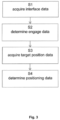
- the present invention reaches the aforementioned object by providing, in a first aspect, a computer-implemented medical method of manipulating at least one first, unmotorised medical carrier structure via a second, motorised medical carrier structure, wherein the at least one first carrier structure comprises at least one first adjustable and selectively fixable joint which respectively connects two sections of the first carrier structure, and in particular comprises at least one first mechanical interface at one or more of the sections and/or at one or more of the fixable joints, specifically at a first predefined section, and wherein the second carrier structure comprises a second mechanical interface and at least one second adjustable and in particular selectively fixable joint which respectively connects two sections of the second carrier structure, the method comprising the following steps:
- the method comprises executing, on at least one processor of at least one computer (for example at least one computer being part of a navigation system), the following exemplary steps which are executed by the at least one processor.
- a mechanical interface of the motorised carrier structure shall engage the unmotorised carrier structure.
- this can be any part of the unmotorised carrier structure which is suited to establish a solid mechanical connection with the mechanical interface of the motorised carrier structure for being moved, along with the first predefined section of the unmotorised carrier structure, to a desired spatial position.
- the term "mechanical interface" can include any active or passive structure that is able to provide a mechanically stable, force transmitting connection between the carrier structures.
- Such engagement section can be for example at any section or joint of the unmotorised carrier structure, as long as it can be connected invariantly to the first predefined section until the latter has reached its target position.
- the unmotorised carrier structure does not feature specifically designed sections for a mechanical interface to engage at.
- a conventional, unmotorised carrier structure "can stay as it is” and does not need to be modified to enable a connection with the mechanical interface of the motorised carrier structure.
- any one or a plurality of the sections and/or joints of the unmotorised carrier structure may comprise a specifically designed engagement section adapted to be gripped by the mechanical interface of the motorised carrier structure.
- such section may be formed as a passive handle or may be formed as an active mechanical interface which corresponds or even may substitute an active mechanical interface of the motorised carrier structure that may then be formed as a passive handle.
- any designated mechanical interface of the motorised carrier structure as well as of the unmotorised carrier structure may be formed by:
- the mechanical interface leaves no degree of freedom for the gripped carrier structure
- other embodiments of the mechanical interface may allow for one or more rotational and/or translational degree(s) of freedom.
- the mechanical interface may comprise jaws having a concave surface in at least one dimension, which may releasably engage a handle having a convex surface in at least one dimension, thereby leaving one or more rotational degrees of freedom for the gripped carrier structure.
- the engagement section of the unmotorised carrier structure may be tracked by a medical tracking system.
- an external tracking system may recognise one or more (optical) tracking markers which indicate the spatial position of the engagement section.
- the engagement section's spatial position may also be derived based on data acquired from position sensors/encoders at the joints of the unmotorised carrier structure, from which the spatial configuration of the unmotorised carrier structure can be calculated.
- the expression "spatial configuration" as used herein is to define the relative positions of the carrier structure's sections with respect to each other. Once the absolute spatial position of one of the sections is known, the absolute spatial position of every other section can be calculated from a model that describes the spatial configuration of the carrier structure.
- the spatial position of the engagement section may however also be determined based on near field communication (NFC) technology.
- the engagement section may feature an RFID-transponder which can be identified by the motorised carrier structure's mechanical interface so as to approach the correct position for engaging with the engagement section.
- the engagement section's spatial position may be shown in an augmented reality (AR)-environment provided to a user with the help of semi-transparent AR-spectacles, AR-googles or similar visualisation devices.
- AR augmented reality
- engage data is calculated based on the interface data, which describes to which spatial position the mechanical interface of the motorised carrier structure needs to be moved in order for it to engage the unmotorised carrier structure.
- control unit which may receive data which describes the spatial configurations of both carrier structures, or at least the relative spatial position between the mechanical interface and the engagement section. Based on this data, the control unit may be adapted to control the motors/actuators as well as an active mechanical interface of the motorised carrier structure to approach and respectively engage the unmotorised carrier structure. For receiving, issuing and/or transmitting data, the control unit may be connected with a respective carrier structure via a wired or a wireless connection.
- target position data is acquired which describes a desired spatial position in which a predefined section of the unmotorised carrier structure is to be positioned to fulfil its purpose, for example for holding a medical instrument at a desired spatial location with a desired spatial orientation.
- positioning data is calculated which describes the necessary movement of the motorised carrier structure to position the predefined section of the unmotorised carrier arm in its desired target position.
- calculating the positioning data may further consider the current spatial configuration of the unmotorised carrier structure, which may not only include the relative position of the sections with respect to each other, but also the range of motion which is currently provided by the respective joints of the unmotorised carrier structure.
- the at least one first joint of the unmotorised carrier structure comprises a controllable first locking mechanism, for example a locking brake, wherein
- the locking brakes of the unmotorised carrier structure are released as soon as the mechanical interface of the motorised carrier structure has engaged the unmotorised carrier structure, wherein the brakes are locked again as soon as the predefined section of the unmotorised carrier structure has reached its desired position and the mechanical interface may therefore release the unmotorised carrier structure again.
- the signals for locking and releasing the locking brakes may be issued by the control unit.
- inventive method may comprise the steps of:
- the unmotorised carrier structure may remain at its desired target position, while the motorised carrier structure may be released therefrom to approach another spatial position, for example to hold a medical device at separate spatial location.
- the motorised carrier structure may proceed with any desired procedure, whilst the unmotorised carrier structure remains stationary at its desired position.
- the first aspect of the present invention also includes a medical carrier system comprising:
- Such medical carrier system may of course comprise any one of the features described above in any meaningful combination.
- the motorised carrier structure and/or the unmotorised carrier structure may be represented by an articulated support arm which has a plurality of sequentially arranged arm sections connected to each other via rotatable joints.
- a first end section of a carrier structure may be a base section that takes a basically invariant spatial position.
- spatially invariant means that the base section maintains its position within an operating theatre for at least a predefined period of time.
- the base section may be disposed on a mobile cart or a similar appliance which maintains its spatial position within the operating theatre while a surgical procedure is carried out.
- the base section may be fixedly mounted to the floor or to the ceiling of the operating theatre.
- the carrier structure may comprise an end section which includes or which fixedly connects to functional components such as an effector for holding or guiding medical instruments or devices with respect to the patient's anatomy.
- the first medical carrier structure comprises at least one first control interface
- the second medical carrier structure comprises at least one second control interface, wherein at least one first control interface and at least one second control interface are adapted to transmit, particularly via a wireless connection, control information between at least two of:
- a first control interface is disposed at the first mechanical interface and a second control interface is disposed at the second mechanical interface, wherein the first control interface and the second control interface are adapted to transmit control information between the first and the second medical carrier structure when the second mechanical interface engages the first carrier structure.
- any of the carrier structures can be adapted to output a signal that indicates whether a force transmitting connection between the unmotorised carrier structure, particularly the mechanical interface thereof, and the mechanical interface of the motorised carrier structure has been established and/or released.
- a release and/or a locking state of a mechanical interface can be indicated to the user via a display, for example an AR-display as described above.
- a warning signal could be output in case the force transmitting connection cannot be established and/or released.
- a computer for example comprises interfaces in order to receive or output data and/or perform an analogue-to-digital conversion.
- the data are for example data which represent physical properties and/or which are generated from technical signals.
- the technical signals are for example generated by means of (technical) detection devices (such as for example devices for detecting marker devices) and/or (technical) analytical devices (such as for example devices for performing (medical) imaging methods), wherein the technical signals are for example electrical or optical signals.
- the technical signals for example represent the data received or outputted by the computer.
- the computer is preferably operatively coupled to a display device which allows information outputted by the computer to be displayed, for example to a user.
- the database or database used for implementing the disclosed method can be located on network data storage device or a network server (for example, a cloud data storage device or a cloud server) or a local data storage device (such as a mass storage device operably connected to at least one computer executing the disclosed method).
- the data can be made "ready for use” by performing an additional step before the acquiring step.
- the data are generated in order to be acquired.
- the data are for example detected or captured (for example by an analytical device).
- the data are inputted in accordance with the additional step, for instance via interfaces.
- the data generated can for example be inputted (for instance into the computer).
- the data can also be provided by performing the additional step of storing the data in a data storage medium (such as for example a ROM, RAM, CD and/or hard drive), such that they are ready for use within the framework of the method or program in accordance with the invention.
- a data storage medium such as for example a ROM, RAM, CD and/or hard drive
- the step of "acquiring data” can therefore also involve commanding a device to obtain and/or provide the data to be acquired.
- the acquiring step does not involve an invasive step which would represent a substantial physical interference with the body, requiring professional medical expertise to be carried out and entailing a substantial health risk even when carried out with the required professional care and expertise.
- the step of acquiring data does not involve a surgical step and in particular does not involve a step of treating a human or animal body using surgery or therapy.
- the data are denoted (i.e. referred to) as "XY data” and the like and are defined in terms of the information which they describe, which is then preferably referred to as "XY information" and the like.
- the navigation system also preferably comprises a user interface for receiving the calculation results from the computer (for example, the position of the main plane, the position of the auxiliary plane and/or the position of the standard plane).
- the user interface provides the received data to the user as information.
- Examples of a user interface include a display device such as a monitor, or a loudspeaker.
- the user interface can use any kind of indication signal (for example a visual signal, an audio signal and/or a vibration signal).
- a display device is an augmented reality device (also referred to as augmented reality glasses) which can be used as so-called "goggles" for navigating.
- Google Glass a trademark of Google, Inc.
- An augmented reality device can be used both to input information into the computer of the navigation system by user interaction and to display information outputted by the computer.
- the disclosure also relates to a navigation system for computer-assisted surgery, comprising:
- a navigation system such as a surgical navigation system, is understood to mean a system which can comprise: at least one marker device; a transmitter which emits electromagnetic waves and/or radiation and/or ultrasound waves; a receiver which receives electromagnetic waves and/or radiation and/or ultrasound waves; and an electronic data processing device which is connected to the receiver and/or the transmitter, wherein the data processing device (for example, a computer) for example comprises a processor (CPU) and a working memory and advantageously an indicating device for issuing an indication signal (for example, a visual indicating device such as a monitor and/or an audio indicating device such as a loudspeaker and/or a tactile indicating device such as a vibrator) and a permanent data memory, wherein the data processing device processes navigation data forwarded to it by the receiver and can advantageously output guidance information to a user via the indicating device.
- the navigation data can be stored in the permanent data memory and for example compared with data stored in said memory beforehand.
- a fixed position which is also referred to as fixed relative position, in this document means that two objects which are in a fixed position have a relative position which does not change unless this change is explicitly and intentionally initiated.
- a fixed position is in particular given if a force or torque above a predetermined threshold has to be applied in order to change the position. This threshold might be 10 N or 10 Nm.
- the position of a sensor device remains fixed relative to a target while the target is registered or two targets are moved relative to each other.
- a fixed position can for example be achieved by rigidly attaching one object to another.
- the spatial location which is a part of the position, can in particular be described just by a distance (between two objects) or just by the direction of a vector (which links two objects).
- the alignment which is another part of the position, can in particular be described by just the relative angle of orientation (between the two objects).
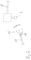
- FIG. 1 schematically shows a motorised support arm 6 which is adapted to manipulate an unmotorised support arm 5 within a surgical environment.
- Both support arms 5, 6 comprise a plurality of rigid arm sections 8, 10, 11 and 13, 15, 16, respectively, which are connected to each other via rotatable joints 9 and 14, respectively, each of which provide one single rotatable degree of freedom.
- the base sections 11 and 16 of the respective support arms are fixedly mounted to a common base, for example, two opposite mounting rails of a patient couch.
- the motorised support arm 6 comprises at its most distal section 13 a mechanical interface 12 along with a control interface 22, which correspond to a mechanical interface 7 and a control interface 21, respectively, provided at the most distal section 8 of the unmotorised support arm(s).
- the actuators within or near the joints 14 are controlled by the control unit 25 within the computer 2 to move the mechanical interface 12 into the mechanical interface 7 of the unmotorised support arm 5, such that the control interfaces 21 and 22 connect each other, as well.
- the mechanical interface 7 features a tapered surface 23 which facilitates the insertion of the mechanical interface 12 into the mechanical interface 7.
- an engaging mechanism (not shown in Figure 1 ) establishes a force transmitting connection between the interfaces 7 and 12, whereupon only those brakes 17 of the unmotorised support arm 5 are released, which lock the joints 9 that provide the necessary degrees of freedom to move the predefined section 8 to a desired target position.
- the brakes 17 are locked again.
- the interfaces 12 and 7 may remain engaged and the brakes 19 of the motorised support arm 6 may also be locked so as to take up load applied via the predefined section 8 with both of the base sections 11 and 16.
- the engagement between the interfaces 12 and 7 as well as the connection between the control interfaces 21 and 22 can be released again such that the most distal section 13 of the motorised support arm 6 can move to a different position as desired.
- an optical tracking system 26 having a stereoscopic camera array can also monitor the spatial position of the mechanical interfaces 7 and 12, for example via tracking markers (not shown in Figure 1 ) attached to at least one of the most distal arm sections 8 and 13, particularly to at least one of the mechanical interfaces 7 and 12.
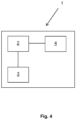
- Figure 4 is a schematic illustration of the medical system 1 according to the fifth aspect.
- the system is in its entirety identified by reference sign 1 and comprises a computer 2, an electronic data storage device (such as a hard disc) 3 for storing at least the target position data and a medical carrier system 4 according to the first aspect.
- the components of the medical system 1 have the functionalities and properties explained above with regard to the fifth aspect of this disclosure.
Landscapes
- Health & Medical Sciences (AREA)
- Surgery (AREA)
- Life Sciences & Earth Sciences (AREA)
- Engineering & Computer Science (AREA)
- Heart & Thoracic Surgery (AREA)
- Animal Behavior & Ethology (AREA)
- Veterinary Medicine (AREA)
- Biomedical Technology (AREA)
- Nuclear Medicine, Radiotherapy & Molecular Imaging (AREA)
- Medical Informatics (AREA)
- Molecular Biology (AREA)
- Public Health (AREA)
- General Health & Medical Sciences (AREA)
- Pathology (AREA)
- Oral & Maxillofacial Surgery (AREA)
- Robotics (AREA)
- Manipulator (AREA)
- Accommodation For Nursing Or Treatment Tables (AREA)
- Prostheses (AREA)
Claims (15)
- Computerimplementiertes medizinisches Verfahren zum Manipulieren wenigstens einer ersten, unmotorisierten medizinischen Trägerstruktur (5) über eine zweite, motorisierte medizinische Trägerstruktur (6), wobei die wenigstens eine erste Trägerstruktur (5) wenigstens eine erste anpassbare und selektiv fixierbare Verbindungsstelle (9) umfasst, die jeweilig zwei Abschnitte (8, 10, 11) der ersten Trägerstruktur (5) verbindet, und insbesondere wenigstens eine erste mechanische Schnittstelle (7) an einem oder mehreren der Abschnitte (8, 10, 11) und/oder an einer oder mehreren der fixierbaren Verbindungsstellen (9), insbesondere an einem ersten vordefinierten Abschnitt (8), umfasst und wobei die zweite Trägerstruktur (6) eine zweite mechanische Schnittstelle (12) und wenigstens eine zweite anpassbare und insbesondere selektiv fixierbare Verbindungsstelle (14) umfasst, die jeweilig zwei Abschnitte (13, 15, 16) der zweiten Trägerstruktur (6) verbindet, wobei das Verfahren die folgenden Schritte umfasst:- Schnittstellendaten werden erfasst (S1), die die räumliche Position (A) eines Abschnitts (8, 10, 11) oder einer Verbindungsstelle (9) der ersten Trägerstruktur (5), insbesondere einer ersten mechanischen Schnittstelle (7), beschreiben, in die durch die zweite mechanische Schnittstelle (12) eingegriffen werden soll;- auf Grundlage der Schnittstellendaten werden Eingriffsdaten bestimmt (S2), die Steuerinformationen beschreiben, um die zweite Trägerstruktur (6) zu veranlassen, die zweite mechanische Schnittstelle (12) in eine räumliche Position (B) zu bewegen, in der die zweite mechanische Schnittstelle (12) in den Abschnitt (8, 10, 11) oder die Verbindungsstelle (9) der ersten Trägerstruktur (5), insbesondere der ersten mechanischen Schnittstelle (7), eingreift;- Zielpositionsdaten werden erfasst (S3), die eine Zielposition (C) für den ersten vordefinierten Abschnitt (8) der ersten Trägerstruktur (5) beschreiben; wobei das Verfahren durch den folgenden Schritt gekennzeichnet ist:- Positionierungsdaten werden bestimmt (S4), die Steuerinformationen beschreiben, um die zweite Trägerstruktur (6) zu veranlassen, den ersten vordefinierten Abschnitt (8) in die Zielposition (C) zu bewegen, nachdem wenigstens eine erste anpassbare und selektiv fixierbare Verbindungsstelle (9) gelöst worden ist.
- Verfahren nach Anspruch 1, wobei die wenigstens eine erste Verbindungsstelle (9) einen steuerbaren ersten Verriegelungsmechanismus (17) umfasst, und wobei- die Eingriffsdaten Steuerinformationen zum Lösen des ersten Verriegelungsmechanismus (17) beinhalten, nachdem die zweite mechanische Schnittstelle (12) in die erste Trägerstruktur (5) eingegriffen hat und/oder bevor die zweite Trägerstruktur (6) den ersten vordefinierten Abschnitt (8) in die Zielposition (C) bewegt; und/oder- die Positionierungsdaten Steuerinformationen zum Verriegeln des ersten Verriegelungsmechanismus (17) beinhalten, nachdem die zweite Trägerstruktur (6) den ersten vordefinierten Abschnitt (8) in die Zielposition (C) bewegt hat.
- Verfahren nach einem der Ansprüche 1 oder 2, wobei die erste mechanische Schnittstelle (7) und/oder die zweite mechanische Schnittstelle (12) einen steuerbaren Eingriffsmechanismus (18) umfasst, und wobei- die Eingriffsdaten Steuerinformationen beinhalten, um den Eingriffsmechanismus (18) zu veranlassen, eine kraftübertragende Verbindung zwischen der ersten und der zweiten Trägerstruktur herzustellen, nachdem die zweite mechanische Schnittstelle (12) in die erste Trägerstruktur (5) eingegriffen hat; und/oder- die Positionierungsdaten Steuerinformationen beinhalten, um den Eingriffsmechanismus (18) zu veranlassen, die kraftübertragende Verbindung zwischen der ersten und der zweiten Trägerstruktur zu lösen, nachdem der erste Verriegelungsmechanismus (17) verriegelt ist.
- Verfahren nach einem der Ansprüche 1 bis 3, wobei die wenigstens eine zweite Verbindungsstelle (14) einen steuerbaren zweiten Verriegelungsmechanismus (19) umfasst, und wobei die Positionierungsdaten Steuerinformationen zum Verriegeln des zweiten Verriegelungsmechanismus (19) beinhalten, nachdem die zweite Trägerstruktur (6) den ersten vordefinierten Abschnitt (8) in die Zielposition (C) bewegt hat, insbesondere nachdem der erste Verriegelungsmechanismus (17) verriegelt wurde.
- Verfahren nach einem der Ansprüche 1 bis 3, das ferner die folgenden Schritte umfasst:- sekundäre Zielpositionsdaten werden erfasst (S5), die eine Zielposition (D) für einen zweiten vordefinierten Abschnitt (13) der zweiten Trägerstruktur (6) beschreiben;- auf Grundlage der sekundären Zielpositionsdaten werden Positionierungsdaten bestimmt (S6), die Steuerinformationen beschreiben, um die zweite Trägerstruktur (6) zu veranlassen, den zweiten vordefinierten Abschnitt (13) in die sekundäre Zielposition (D) zu bewegen.
- Medizinisches Trägersystem (4), beinhaltend:- wenigstens eine erste, unmotorisierte medizinische Trägerstruktur (5), die wenigstens eine erste anpassbare und selektiv fixierbare Verbindungsstelle (9) umfasst, die jeweilig zwei Abschnitte (8, 10, 11) der ersten Trägerstruktur (5) verbindet, und insbesondere wenigstens eine erste mechanische Schnittstelle (7) an einem oder mehreren der Abschnitte (8, 10, 11) und/oder an einer oder mehreren der fixierbaren Verbindungsstellen (9), insbesondere an einem ersten vordefinierten Abschnitt (8), umfasst;- eine zweite, motorisierte medizinische Trägerstruktur (6), die eine zweite mechanische Schnittstelle (12) und wenigstens eine zweite anpassbare und insbesondere selektiv fixierbare Verbindungsstelle (14) umfasst, die jeweilig zwei Abschnitte (13, 15, 16) der zweiten Trägerstruktur (6) verbindet,wobei die zweite Trägerstruktur (6) von einer Steuereinheit (25) gesteuert wird, die die Verfahrensschritte nach Anspruch 1 durchführt, um die zweite mechanische Schnittstelle (12) in eine räumliche Position zu bewegen, in der die zweite mechanische Schnittstelle (12) in die unmotorisierte medizinische Trägerstruktur (5), insbesondere die erste mechanische Schnittstelle (7) davon, eingreift, und um den ersten vordefinierten Abschnitt (8) in eine Zielposition (C) zu bewegen.
- System nach Anspruch 6, wobei- die erste Trägerstruktur (5) eine Mehrzahl von ersten Verbindungsstellen (9) umfasst, wobei jede der ersten Verbindungsstellen (9) jeweilig zwei Abschnitte (8, 10, 11) der ersten Trägerstruktur (5) verbindet; und/oder- die zweite Trägerstruktur (6) eine Mehrzahl von zweiten Verbindungsstellen (14) umfasst, wobei jede der zweiten Verbindungsstellen (14) jeweilig zwei Abschnitte (13, 15, 16) der zweiten Trägerstruktur (6) verbindet; und/oder- wenigstens eine erste Verbindungsstelle (9) und/oder wenigstens eine zweite Verbindungsstelle (14) ein Drehverbindungsstelle ist, die einen Rotationsfreiheitsgrad bereitstellt; und/oder- wenigstens eine erste Verbindungsstelle (9) und/oder wenigstens eine zweite Verbindungsstelle (14) einen Positionssensor (20) umfasst, der angepasst ist, um die relative Position der Abschnitte (8, 10, 11, 13, 15, 16) zu bestimmen, die über die jeweilige Verbindungsstelle (9, 14) verbunden sind; und/oder- der erste vordefinierte Abschnitt (8) ein Endabschnitt der ersten Trägerstruktur (5) ist und/oder der zweite vordefinierte Abschnitt (13) ein Endabschnitt der zweiten Trägerstruktur (6) ist; und/oder- die erste Trägerstruktur (5) einen räumlich unveränderlichen ersten Basisabschnitt (11) umfasst, der über die wenigstens eine erste Verbindungsstelle (9), insbesondere über wenigstens einen ersten Zwischenabschnitt (10), mit dem ersten vordefinierten Abschnitt (8) verbunden ist; und/oder- die zweite Trägerstruktur (6) einen räumlich unveränderlichen zweiten Basisabschnitt (16) umfasst, der über die wenigstens eine zweite Verbindungsstelle (14), insbesondere über wenigstens einen zweiten Zwischenabschnitt (13), mit dem zweiten vordefinierten Abschnitt (15) verbunden ist.
- System nach einem der Ansprüche 6 oder 7, wobei die erste medizinische Trägerstruktur (5) wenigstens eine erste Steuerschnittstelle (21) umfasst und die zweite medizinische Trägerstruktur (6) wenigstens eine zweite Steuerschnittstelle (22) umfasst, wobei wenigstens eine erste Steuerschnittstelle (21) und wenigstens eine zweite Steuerschnittstelle (22) angepasst sind, insbesondere über eine drahtlose Verbindung, Steuerinformationen zwischen wenigstens zwei zu übertragen, von:- der ersten medizinischen Trägerstruktur (5);- der zweiten medizinischen Trägerstruktur (6);- einer gemeinsamen Steuereinheit (25), die angepasst ist, die erste medizinische Trägerstruktur (5) und/oder die zweite medizinische Trägerstruktur (6) zu steuern, insbesondere wobei eine der ersten (5) und der zweiten (6) medizinischen Trägerstruktur über die Steuerschnittstelle (21, 22) der jeweilig anderen medizinischen Trägerstruktur (5, 6) gesteuert wird.
- System nach Anspruch 8, wobei eine erste Steuerschnittstelle (21) an der ersten mechanischen Schnittstelle (7) angeordnet ist und eine zweite Steuerschnittstelle (22) an der zweiten mechanischen Schnittstelle (12) angeordnet ist, wobei die erste Steuerschnittstelle (21) und die zweite Steuerschnittstelle (22) angepasst sind, um Steuerinformationen zwischen der ersten (5) und der zweiten (6) medizinischen Trägerstruktur zu übertragen, wenn die zweite mechanische Schnittstelle (12) in die erste Trägerstruktur (5) eingreift.
- System nach einem der Ansprüche 6 bis 9, wobei die erste mechanische Schnittstelle (7) und/oder die zweite mechanische Schnittstelle (12) durch einen Halte- und/oder Greifabschnitt gebildet ist, der insbesondere zum Halten und/oder Greifen eines medizinischen Instruments oder einer medizinischen Vorrichtung angepasst ist.
- System nach einem der Ansprüche 6 bis 10, wobei die erste mechanische Schnittstelle (7) und/oder die zweite mechanische Schnittstelle (12) wenigstens eines umfasst von:- einem steuerbaren Eingriffsmechanismus (18), der angepasst ist, um eine kraftübertragende Verbindung zwischen der ersten Trägerstruktur (5), insbesondere der ersten mechanischen Schnittstelle (7) und der zweiten mechanischen Schnittstelle (12), insbesondere einer lösbaren formschlüssigen Passung herzustellen oder aufzuheben;- einer Positionierungshilfe (23), die dazu konfiguriert ist, die Positionierung der zweiten mechanischen Schnittstelle (12) in einer räumlichen Position (B) zu unterstützen, in der die zweite mechanische Schnittstelle (12) in die erste Trägerstruktur (5), insbesondere die erste mechanische Schnittstelle (7), eingreift, insbesondere eine magnetische und/oder eine physikalische Positionierungshilfe.
- System nach einem der Ansprüche 6 bis 11, wobei die erste medizinische Trägerstruktur (5) und/oder die zweite medizinische Trägerstruktur (6) angepasst ist, um ein Signal auszugeben, das anzeigt, ob eine kraftübertragende Verbindung zwischen der ersten Trägerstruktur (5), insbesondere der ersten mechanischen Schnittstelle (7) und der zweiten mechanischen Schnittstelle (12) hergestellt und/oder gelöst wurde.
- System nach einem der Ansprüche 6 bis 12, wobei die erste mechanische Schnittstelle (7) und die zweite mechanische Schnittstelle (12) angepasst sind, um eine Last aufzunehmen, die wesentlich höher ist als die Last, die durch die Bewegung der ersten medizinischen Trägerstruktur (5) über die zweite medizinische Trägerstruktur (6) auf die Schnittstellen (7, 12) ausgeübt wird.
- Computerprogramm, das Anweisungen umfasst, die, wenn das Programm von einem Computer (2) ausgeführt wird, den Computer (2) veranlassen, das Verfahren nach einem der Ansprüche 1 bis 5 auszuführen.
- Medizinisches System (1), umfassend:a) wenigstens einen Computer (2), der das Computerprogramm nach Anspruch 14 ausführt;b) wenigstens eine elektronische Datenspeichervorrichtung (3), die wenigstens die Zielpositionsdaten speichert; undc) ein medizinisches Trägersystem (4) nach einem der Ansprüche 6 bis 13, wobei der wenigstens eine Computer (2) betriebsfähig gekoppelt ist mit- der wenigstens einen elektronischen Datenspeichervorrichtung (3), um von der wenigstens einen Datenspeichervorrichtung (3) wenigstens die Zielpositionsdaten zu erfassen, und- dem medizinischen Trägersystem (4) zum Ausgeben eines Steuersignals an das medizinische Trägersystem (4) zum Steuern des Betriebs des medizinischen Trägersystems (4) auf Grundlage der Zielpositionsdaten.
Applications Claiming Priority (1)
| Application Number | Priority Date | Filing Date | Title |
|---|---|---|---|
| PCT/EP2020/069018 WO2022008034A1 (en) | 2020-07-06 | 2020-07-06 | Robotic manipulation of medical carrier structures |
Publications (2)
| Publication Number | Publication Date |
|---|---|
| EP4175579A1 EP4175579A1 (de) | 2023-05-10 |
| EP4175579B1 true EP4175579B1 (de) | 2025-04-16 |
Family
ID=71579563
Family Applications (1)
| Application Number | Title | Priority Date | Filing Date |
|---|---|---|---|
| EP20739600.3A Active EP4175579B1 (de) | 2020-07-06 | 2020-07-06 | Robotische manipulation von medizinischen trägerstrukturen |
Country Status (4)
| Country | Link |
|---|---|
| US (1) | US12390289B2 (de) |
| EP (1) | EP4175579B1 (de) |
| IL (1) | IL299682B2 (de) |
| WO (1) | WO2022008034A1 (de) |
Families Citing this family (2)
| Publication number | Priority date | Publication date | Assignee | Title |
|---|---|---|---|---|
| WO2018059838A1 (en) * | 2016-09-27 | 2018-04-05 | Brainlab Ag | Efficient positioning of a mechatronic arm |
| US20250339969A1 (en) * | 2022-05-24 | 2025-11-06 | Brainlab Ag | Robotic calibration |
Family Cites Families (6)
| Publication number | Priority date | Publication date | Assignee | Title |
|---|---|---|---|---|
| US6659939B2 (en) * | 1998-11-20 | 2003-12-09 | Intuitive Surgical, Inc. | Cooperative minimally invasive telesurgical system |
| US6645196B1 (en) * | 2000-06-16 | 2003-11-11 | Intuitive Surgical, Inc. | Guided tool change |
| JP2010274396A (ja) * | 2009-06-01 | 2010-12-09 | Kawasaki Heavy Ind Ltd | 自動作業システムにおける位置ズレ補正方法及び位置ズレ補正プログラム |
| EP3518854B8 (de) | 2016-11-28 | 2026-05-20 | Auris Health Inc | Robotergestütztes chirurgisches system zur reduzierung unerwünschter vibrationen |
| WO2020020432A1 (en) * | 2018-07-23 | 2020-01-30 | Brainlab Ag | Articulated robotic platform |
| EP3873369A1 (de) * | 2018-10-31 | 2021-09-08 | Intuitive Surgical Operations, Inc. | System und verfahren zur unterstützung des werkzeugwechsels |
-
2020
- 2020-07-06 IL IL299682A patent/IL299682B2/en unknown
- 2020-07-06 US US18/009,547 patent/US12390289B2/en active Active
- 2020-07-06 EP EP20739600.3A patent/EP4175579B1/de active Active
- 2020-07-06 WO PCT/EP2020/069018 patent/WO2022008034A1/en not_active Ceased
Also Published As
| Publication number | Publication date |
|---|---|
| EP4175579A1 (de) | 2023-05-10 |
| US12390289B2 (en) | 2025-08-19 |
| US20230225805A1 (en) | 2023-07-20 |
| IL299682A (en) | 2023-03-01 |
| IL299682B1 (en) | 2026-01-01 |
| IL299682B2 (en) | 2026-05-01 |
| WO2022008034A1 (en) | 2022-01-13 |
Similar Documents
| Publication | Publication Date | Title |
|---|---|---|
| JP7233841B2 (ja) | ロボット外科手術システムのロボットナビゲーション | |
| US11213364B2 (en) | Image guided motion scaling for robot control | |
| EP3429498B1 (de) | System zur optischen verfolgung | |
| EP2148629B1 (de) | Rahmenzuordnungs- und kraftrückkopplungsverfahren, -vorrichtungen und -systeme | |
| CN112472297A (zh) | 位姿监测系统、方法、手术机器人系统和存储介质 | |
| EP4700748A2 (de) | Patientenspezifische präoperative planungssimulationstechniken | |
| CN103705307A (zh) | 手术导航系统及医疗机器人 | |
| JP2018513711A (ja) | 非常に器用なシステムのユーザインタフェース | |
| EP3328308B1 (de) | Effiziente positionierung eines mechatronischen arms | |
| US20220022968A1 (en) | Computer input method using a digitizer as an input device | |
| WO2020020749A1 (en) | Articulated robotic platform | |
| CN110072483A (zh) | 对依赖性外科手术机器人臂的自动运动控制 | |
| US12390289B2 (en) | Robotic manipulation of medical carrier structures | |
| WO2015172826A1 (en) | Method for determining the spatial position of objects | |
| KR20220024055A (ko) | 추적 시스템 시야 위치설정 시스템 및 방법 | |
| EP3944734B1 (de) | Kompensation von schwerkraftbedingten verschiebungen von medizinischen trägerstrukturen | |
| EP3664742B1 (de) | Videobasierte mikroskopeinstellung | |
| US12539156B2 (en) | Robotic hand-held surgical instrument systems and methods | |
| US11589934B2 (en) | Efficient brake boost for mechatronic articulable arm | |
| EP4196036B1 (de) | Bestimmung eines vermeidungsbereichs für eine referenzvorrichtung | |
| WO2025124884A1 (en) | Head clamp system | |
| US20250339969A1 (en) | Robotic calibration | |
| EP4401639B1 (de) | Segmentierte ultraschallsonde |
Legal Events
| Date | Code | Title | Description |
|---|---|---|---|
| STAA | Information on the status of an ep patent application or granted ep patent |
Free format text: STATUS: UNKNOWN |
|
| STAA | Information on the status of an ep patent application or granted ep patent |
Free format text: STATUS: THE INTERNATIONAL PUBLICATION HAS BEEN MADE |
|
| PUAI | Public reference made under article 153(3) epc to a published international application that has entered the european phase |
Free format text: ORIGINAL CODE: 0009012 |
|
| STAA | Information on the status of an ep patent application or granted ep patent |
Free format text: STATUS: REQUEST FOR EXAMINATION WAS MADE |
|
| 17P | Request for examination filed |
Effective date: 20230119 |
|
| AK | Designated contracting states |
Kind code of ref document: A1 Designated state(s): AL AT BE BG CH CY CZ DE DK EE ES FI FR GB GR HR HU IE IS IT LI LT LU LV MC MK MT NL NO PL PT RO RS SE SI SK SM TR |
|
| DAV | Request for validation of the european patent (deleted) | ||
| DAX | Request for extension of the european patent (deleted) | ||
| GRAP | Despatch of communication of intention to grant a patent |
Free format text: ORIGINAL CODE: EPIDOSNIGR1 |
|
| STAA | Information on the status of an ep patent application or granted ep patent |
Free format text: STATUS: GRANT OF PATENT IS INTENDED |
|
| INTG | Intention to grant announced |
Effective date: 20241205 |
|
| P01 | Opt-out of the competence of the unified patent court (upc) registered |
Free format text: CASE NUMBER: APP_2752/2025 Effective date: 20250116 |
|
| GRAS | Grant fee paid |
Free format text: ORIGINAL CODE: EPIDOSNIGR3 |
|
| GRAA | (expected) grant |
Free format text: ORIGINAL CODE: 0009210 |
|
| STAA | Information on the status of an ep patent application or granted ep patent |
Free format text: STATUS: THE PATENT HAS BEEN GRANTED |
|
| AK | Designated contracting states |
Kind code of ref document: B1 Designated state(s): AL AT BE BG CH CY CZ DE DK EE ES FI FR GB GR HR HU IE IS IT LI LT LU LV MC MK MT NL NO PL PT RO RS SE SI SK SM TR |
|
| REG | Reference to a national code |
Ref country code: GB Ref legal event code: FG4D |
|
| REG | Reference to a national code |
Ref country code: CH Ref legal event code: EP |
|
| REG | Reference to a national code |
Ref country code: IE Ref legal event code: FG4D |
|
| REG | Reference to a national code |
Ref country code: DE Ref legal event code: R096 Ref document number: 602020049537 Country of ref document: DE |
|
| REG | Reference to a national code |
Ref country code: NL Ref legal event code: MP Effective date: 20250416 |
|
| PG25 | Lapsed in a contracting state [announced via postgrant information from national office to epo] |
Ref country code: NL Free format text: LAPSE BECAUSE OF FAILURE TO SUBMIT A TRANSLATION OF THE DESCRIPTION OR TO PAY THE FEE WITHIN THE PRESCRIBED TIME-LIMIT Effective date: 20250416 |
|
| REG | Reference to a national code |
Ref country code: AT Ref legal event code: MK05 Ref document number: 1785020 Country of ref document: AT Kind code of ref document: T Effective date: 20250416 Ref country code: DE Ref legal event code: R081 Ref document number: 602020049537 Country of ref document: DE Owner name: BRAINLAB SE, DE Free format text: FORMER OWNER: BRAINLAB AG, 81829 MUENCHEN, DE |
|
| PG25 | Lapsed in a contracting state [announced via postgrant information from national office to epo] |
Ref country code: FI Free format text: LAPSE BECAUSE OF FAILURE TO SUBMIT A TRANSLATION OF THE DESCRIPTION OR TO PAY THE FEE WITHIN THE PRESCRIBED TIME-LIMIT Effective date: 20250416 Ref country code: ES Free format text: LAPSE BECAUSE OF FAILURE TO SUBMIT A TRANSLATION OF THE DESCRIPTION OR TO PAY THE FEE WITHIN THE PRESCRIBED TIME-LIMIT Effective date: 20250416 Ref country code: PT Free format text: LAPSE BECAUSE OF FAILURE TO SUBMIT A TRANSLATION OF THE DESCRIPTION OR TO PAY THE FEE WITHIN THE PRESCRIBED TIME-LIMIT Effective date: 20250818 |
|
| PGFP | Annual fee paid to national office [announced via postgrant information from national office to epo] |
Ref country code: DE Payment date: 20250722 Year of fee payment: 6 |
|
| REG | Reference to a national code |
Ref country code: LT Ref legal event code: MG9D |
|
| PG25 | Lapsed in a contracting state [announced via postgrant information from national office to epo] |
Ref country code: GR Free format text: LAPSE BECAUSE OF FAILURE TO SUBMIT A TRANSLATION OF THE DESCRIPTION OR TO PAY THE FEE WITHIN THE PRESCRIBED TIME-LIMIT Effective date: 20250717 Ref country code: NO Free format text: LAPSE BECAUSE OF FAILURE TO SUBMIT A TRANSLATION OF THE DESCRIPTION OR TO PAY THE FEE WITHIN THE PRESCRIBED TIME-LIMIT Effective date: 20250716 |
|
| PG25 | Lapsed in a contracting state [announced via postgrant information from national office to epo] |
Ref country code: PL Free format text: LAPSE BECAUSE OF FAILURE TO SUBMIT A TRANSLATION OF THE DESCRIPTION OR TO PAY THE FEE WITHIN THE PRESCRIBED TIME-LIMIT Effective date: 20250416 |
|
| PG25 | Lapsed in a contracting state [announced via postgrant information from national office to epo] |
Ref country code: BG Free format text: LAPSE BECAUSE OF FAILURE TO SUBMIT A TRANSLATION OF THE DESCRIPTION OR TO PAY THE FEE WITHIN THE PRESCRIBED TIME-LIMIT Effective date: 20250416 |
|
| PG25 | Lapsed in a contracting state [announced via postgrant information from national office to epo] |
Ref country code: HR Free format text: LAPSE BECAUSE OF FAILURE TO SUBMIT A TRANSLATION OF THE DESCRIPTION OR TO PAY THE FEE WITHIN THE PRESCRIBED TIME-LIMIT Effective date: 20250416 |
|
| PG25 | Lapsed in a contracting state [announced via postgrant information from national office to epo] |
Ref country code: AT Free format text: LAPSE BECAUSE OF FAILURE TO SUBMIT A TRANSLATION OF THE DESCRIPTION OR TO PAY THE FEE WITHIN THE PRESCRIBED TIME-LIMIT Effective date: 20250416 |
|
| PGFP | Annual fee paid to national office [announced via postgrant information from national office to epo] |
Ref country code: FR Payment date: 20250725 Year of fee payment: 6 |
|
| PG25 | Lapsed in a contracting state [announced via postgrant information from national office to epo] |
Ref country code: RS Free format text: LAPSE BECAUSE OF FAILURE TO SUBMIT A TRANSLATION OF THE DESCRIPTION OR TO PAY THE FEE WITHIN THE PRESCRIBED TIME-LIMIT Effective date: 20250716 |
|
| RAP4 | Party data changed (patent owner data changed or rights of a patent transferred) |
Owner name: BRAINLAB SE |
|
| PG25 | Lapsed in a contracting state [announced via postgrant information from national office to epo] |
Ref country code: IS Free format text: LAPSE BECAUSE OF FAILURE TO SUBMIT A TRANSLATION OF THE DESCRIPTION OR TO PAY THE FEE WITHIN THE PRESCRIBED TIME-LIMIT Effective date: 20250816 |
|
| PG25 | Lapsed in a contracting state [announced via postgrant information from national office to epo] |
Ref country code: LV Free format text: LAPSE BECAUSE OF FAILURE TO SUBMIT A TRANSLATION OF THE DESCRIPTION OR TO PAY THE FEE WITHIN THE PRESCRIBED TIME-LIMIT Effective date: 20250416 |
|
| PG25 | Lapsed in a contracting state [announced via postgrant information from national office to epo] |
Ref country code: DK Free format text: LAPSE BECAUSE OF FAILURE TO SUBMIT A TRANSLATION OF THE DESCRIPTION OR TO PAY THE FEE WITHIN THE PRESCRIBED TIME-LIMIT Effective date: 20250416 Ref country code: SM Free format text: LAPSE BECAUSE OF FAILURE TO SUBMIT A TRANSLATION OF THE DESCRIPTION OR TO PAY THE FEE WITHIN THE PRESCRIBED TIME-LIMIT Effective date: 20250416 |
|
| REG | Reference to a national code |
Ref country code: DE Ref legal event code: R097 Ref document number: 602020049537 Country of ref document: DE |
|
| PG25 | Lapsed in a contracting state [announced via postgrant information from national office to epo] |
Ref country code: CZ Free format text: LAPSE BECAUSE OF FAILURE TO SUBMIT A TRANSLATION OF THE DESCRIPTION OR TO PAY THE FEE WITHIN THE PRESCRIBED TIME-LIMIT Effective date: 20250416 |
|
| PG25 | Lapsed in a contracting state [announced via postgrant information from national office to epo] |
Ref country code: EE Free format text: LAPSE BECAUSE OF FAILURE TO SUBMIT A TRANSLATION OF THE DESCRIPTION OR TO PAY THE FEE WITHIN THE PRESCRIBED TIME-LIMIT Effective date: 20250416 |
|
| PG25 | Lapsed in a contracting state [announced via postgrant information from national office to epo] |
Ref country code: SK Free format text: LAPSE BECAUSE OF FAILURE TO SUBMIT A TRANSLATION OF THE DESCRIPTION OR TO PAY THE FEE WITHIN THE PRESCRIBED TIME-LIMIT Effective date: 20250416 |
|
| PG25 | Lapsed in a contracting state [announced via postgrant information from national office to epo] |
Ref country code: IT Free format text: LAPSE BECAUSE OF FAILURE TO SUBMIT A TRANSLATION OF THE DESCRIPTION OR TO PAY THE FEE WITHIN THE PRESCRIBED TIME-LIMIT Effective date: 20250416 |
|
| PLBE | No opposition filed within time limit |
Free format text: ORIGINAL CODE: 0009261 |
|
| STAA | Information on the status of an ep patent application or granted ep patent |
Free format text: STATUS: NO OPPOSITION FILED WITHIN TIME LIMIT |
|
| REG | Reference to a national code |
Ref country code: CH Ref legal event code: H13 Free format text: ST27 STATUS EVENT CODE: U-0-0-H10-H13 (AS PROVIDED BY THE NATIONAL OFFICE) Effective date: 20260224 |
|
| REG | Reference to a national code |
Ref country code: CH Ref legal event code: L10 Free format text: ST27 STATUS EVENT CODE: U-0-0-L10-L00 (AS PROVIDED BY THE NATIONAL OFFICE) Effective date: 20260225 |
|
| PG25 | Lapsed in a contracting state [announced via postgrant information from national office to epo] |
Ref country code: RO Free format text: LAPSE BECAUSE OF FAILURE TO SUBMIT A TRANSLATION OF THE DESCRIPTION OR TO PAY THE FEE WITHIN THE PRESCRIBED TIME-LIMIT Effective date: 20250416 |
|
| PG25 | Lapsed in a contracting state [announced via postgrant information from national office to epo] |
Ref country code: LU Free format text: LAPSE BECAUSE OF NON-PAYMENT OF DUE FEES Effective date: 20250706 |
|
| 26N | No opposition filed |
Effective date: 20260119 |
|
| GBPC | Gb: european patent ceased through non-payment of renewal fee |
Effective date: 20250716 |
|
| REG | Reference to a national code |
Ref country code: BE Ref legal event code: MM Effective date: 20250731 |
|
| PG25 | Lapsed in a contracting state [announced via postgrant information from national office to epo] |
Ref country code: GB Free format text: LAPSE BECAUSE OF NON-PAYMENT OF DUE FEES Effective date: 20250716 |
|
| PG25 | Lapsed in a contracting state [announced via postgrant information from national office to epo] |
Ref country code: BE Free format text: LAPSE BECAUSE OF NON-PAYMENT OF DUE FEES Effective date: 20250731 |
|
| PG25 | Lapsed in a contracting state [announced via postgrant information from national office to epo] |
Ref country code: CH Free format text: LAPSE BECAUSE OF NON-PAYMENT OF DUE FEES Effective date: 20250731 |