EP4175703B1 - Appareil de thérapie respiratoire - Google Patents
Appareil de thérapie respiratoire Download PDFInfo
- Publication number
- EP4175703B1 EP4175703B1 EP21722237.1A EP21722237A EP4175703B1 EP 4175703 B1 EP4175703 B1 EP 4175703B1 EP 21722237 A EP21722237 A EP 21722237A EP 4175703 B1 EP4175703 B1 EP 4175703B1
- Authority
- EP
- European Patent Office
- Prior art keywords
- hollow body
- respiratory therapy
- tongue
- therapy device
- stenosis
- Prior art date
- Legal status (The legal status is an assumption and is not a legal conclusion. Google has not performed a legal analysis and makes no representation as to the accuracy of the status listed.)
- Active
Links
Images


Classifications
-
- A—HUMAN NECESSITIES
- A61—MEDICAL OR VETERINARY SCIENCE; HYGIENE
- A61M—DEVICES FOR INTRODUCING MEDIA INTO, OR ONTO, THE BODY; DEVICES FOR TRANSDUCING BODY MEDIA OR FOR TAKING MEDIA FROM THE BODY; DEVICES FOR PRODUCING OR ENDING SLEEP OR STUPOR
- A61M16/00—Devices for influencing the respiratory system of patients by gas treatment, e.g. ventilators; Tracheal tubes
- A61M16/0003—Accessories therefor, e.g. sensors, vibrators, negative pressure
- A61M16/0006—Accessories therefor, e.g. sensors, vibrators, negative pressure with means for creating vibrations in patients' airways
-
- A—HUMAN NECESSITIES
- A61—MEDICAL OR VETERINARY SCIENCE; HYGIENE
- A61M—DEVICES FOR INTRODUCING MEDIA INTO, OR ONTO, THE BODY; DEVICES FOR TRANSDUCING BODY MEDIA OR FOR TAKING MEDIA FROM THE BODY; DEVICES FOR PRODUCING OR ENDING SLEEP OR STUPOR
- A61M16/00—Devices for influencing the respiratory system of patients by gas treatment, e.g. ventilators; Tracheal tubes
- A61M16/08—Bellows; Connecting tubes ; Water traps; Patient circuits
- A61M16/0866—Passive resistors therefor
-
- A—HUMAN NECESSITIES
- A61—MEDICAL OR VETERINARY SCIENCE; HYGIENE
- A61M—DEVICES FOR INTRODUCING MEDIA INTO, OR ONTO, THE BODY; DEVICES FOR TRANSDUCING BODY MEDIA OR FOR TAKING MEDIA FROM THE BODY; DEVICES FOR PRODUCING OR ENDING SLEEP OR STUPOR
- A61M16/00—Devices for influencing the respiratory system of patients by gas treatment, e.g. ventilators; Tracheal tubes
- A61M16/20—Valves specially adapted to medical respiratory devices
-
- A—HUMAN NECESSITIES
- A61—MEDICAL OR VETERINARY SCIENCE; HYGIENE
- A61M—DEVICES FOR INTRODUCING MEDIA INTO, OR ONTO, THE BODY; DEVICES FOR TRANSDUCING BODY MEDIA OR FOR TAKING MEDIA FROM THE BODY; DEVICES FOR PRODUCING OR ENDING SLEEP OR STUPOR
- A61M16/00—Devices for influencing the respiratory system of patients by gas treatment, e.g. ventilators; Tracheal tubes
- A61M16/20—Valves specially adapted to medical respiratory devices
- A61M16/208—Non-controlled one-way valves, e.g. exhalation, check, pop-off non-rebreathing valves
-
- A—HUMAN NECESSITIES
- A63—SPORTS; GAMES; AMUSEMENTS
- A63B—APPARATUS FOR PHYSICAL TRAINING, GYMNASTICS, SWIMMING, CLIMBING, OR FENCING; BALL GAMES; TRAINING EQUIPMENT
- A63B21/00—Exercising apparatus for developing or strengthening the muscles or joints of the body by working against a counterforce, with or without measuring devices
- A63B21/00196—Exercising apparatus for developing or strengthening the muscles or joints of the body by working against a counterforce, with or without measuring devices using pulsed counterforce, e.g. vibrating resistance means
-
- A—HUMAN NECESSITIES
- A61—MEDICAL OR VETERINARY SCIENCE; HYGIENE
- A61M—DEVICES FOR INTRODUCING MEDIA INTO, OR ONTO, THE BODY; DEVICES FOR TRANSDUCING BODY MEDIA OR FOR TAKING MEDIA FROM THE BODY; DEVICES FOR PRODUCING OR ENDING SLEEP OR STUPOR
- A61M16/00—Devices for influencing the respiratory system of patients by gas treatment, e.g. ventilators; Tracheal tubes
- A61M16/04—Tracheal tubes
- A61M16/0488—Mouthpieces; Means for guiding, securing or introducing the tubes
-
- A—HUMAN NECESSITIES
- A61—MEDICAL OR VETERINARY SCIENCE; HYGIENE
- A61M—DEVICES FOR INTRODUCING MEDIA INTO, OR ONTO, THE BODY; DEVICES FOR TRANSDUCING BODY MEDIA OR FOR TAKING MEDIA FROM THE BODY; DEVICES FOR PRODUCING OR ENDING SLEEP OR STUPOR
- A61M16/00—Devices for influencing the respiratory system of patients by gas treatment, e.g. ventilators; Tracheal tubes
- A61M16/08—Bellows; Connecting tubes ; Water traps; Patient circuits
- A61M16/0816—Joints or connectors
-
- A—HUMAN NECESSITIES
- A61—MEDICAL OR VETERINARY SCIENCE; HYGIENE
- A61M—DEVICES FOR INTRODUCING MEDIA INTO, OR ONTO, THE BODY; DEVICES FOR TRANSDUCING BODY MEDIA OR FOR TAKING MEDIA FROM THE BODY; DEVICES FOR PRODUCING OR ENDING SLEEP OR STUPOR
- A61M16/00—Devices for influencing the respiratory system of patients by gas treatment, e.g. ventilators; Tracheal tubes
- A61M16/08—Bellows; Connecting tubes ; Water traps; Patient circuits
- A61M16/0883—Circuit type
-
- A—HUMAN NECESSITIES
- A61—MEDICAL OR VETERINARY SCIENCE; HYGIENE
- A61M—DEVICES FOR INTRODUCING MEDIA INTO, OR ONTO, THE BODY; DEVICES FOR TRANSDUCING BODY MEDIA OR FOR TAKING MEDIA FROM THE BODY; DEVICES FOR PRODUCING OR ENDING SLEEP OR STUPOR
- A61M16/00—Devices for influencing the respiratory system of patients by gas treatment, e.g. ventilators; Tracheal tubes
- A61M16/20—Valves specially adapted to medical respiratory devices
- A61M16/201—Controlled valves
-
- A—HUMAN NECESSITIES
- A61—MEDICAL OR VETERINARY SCIENCE; HYGIENE
- A61M—DEVICES FOR INTRODUCING MEDIA INTO, OR ONTO, THE BODY; DEVICES FOR TRANSDUCING BODY MEDIA OR FOR TAKING MEDIA FROM THE BODY; DEVICES FOR PRODUCING OR ENDING SLEEP OR STUPOR
- A61M2205/00—General characteristics of the apparatus
- A61M2205/33—Controlling, regulating or measuring
- A61M2205/3331—Pressure; Flow
- A61M2205/3334—Measuring or controlling the flow rate
-
- A—HUMAN NECESSITIES
- A61—MEDICAL OR VETERINARY SCIENCE; HYGIENE
- A61M—DEVICES FOR INTRODUCING MEDIA INTO, OR ONTO, THE BODY; DEVICES FOR TRANSDUCING BODY MEDIA OR FOR TAKING MEDIA FROM THE BODY; DEVICES FOR PRODUCING OR ENDING SLEEP OR STUPOR
- A61M2205/00—General characteristics of the apparatus
- A61M2205/33—Controlling, regulating or measuring
- A61M2205/3375—Acoustical, e.g. ultrasonic, measuring means
-
- A—HUMAN NECESSITIES
- A61—MEDICAL OR VETERINARY SCIENCE; HYGIENE
- A61M—DEVICES FOR INTRODUCING MEDIA INTO, OR ONTO, THE BODY; DEVICES FOR TRANSDUCING BODY MEDIA OR FOR TAKING MEDIA FROM THE BODY; DEVICES FOR PRODUCING OR ENDING SLEEP OR STUPOR
- A61M2205/00—General characteristics of the apparatus
- A61M2205/35—Communication
- A61M2205/3576—Communication with non implanted data transmission devices, e.g. using external transmitter or receiver
- A61M2205/3592—Communication with non implanted data transmission devices, e.g. using external transmitter or receiver using telemetric means, e.g. radio or optical transmission
-
- A—HUMAN NECESSITIES
- A61—MEDICAL OR VETERINARY SCIENCE; HYGIENE
- A61M—DEVICES FOR INTRODUCING MEDIA INTO, OR ONTO, THE BODY; DEVICES FOR TRANSDUCING BODY MEDIA OR FOR TAKING MEDIA FROM THE BODY; DEVICES FOR PRODUCING OR ENDING SLEEP OR STUPOR
- A61M2205/00—General characteristics of the apparatus
- A61M2205/50—General characteristics of the apparatus with microprocessors or computers
- A61M2205/52—General characteristics of the apparatus with microprocessors or computers with memories providing a history of measured variating parameters of apparatus or patient
-
- A—HUMAN NECESSITIES
- A61—MEDICAL OR VETERINARY SCIENCE; HYGIENE
- A61M—DEVICES FOR INTRODUCING MEDIA INTO, OR ONTO, THE BODY; DEVICES FOR TRANSDUCING BODY MEDIA OR FOR TAKING MEDIA FROM THE BODY; DEVICES FOR PRODUCING OR ENDING SLEEP OR STUPOR
- A61M2205/00—General characteristics of the apparatus
- A61M2205/58—Means for facilitating use, e.g. by people with impaired vision
- A61M2205/581—Means for facilitating use, e.g. by people with impaired vision by audible feedback
-
- A—HUMAN NECESSITIES
- A63—SPORTS; GAMES; AMUSEMENTS
- A63B—APPARATUS FOR PHYSICAL TRAINING, GYMNASTICS, SWIMMING, CLIMBING, OR FENCING; BALL GAMES; TRAINING EQUIPMENT
- A63B71/00—Games or sports accessories not covered in groups A63B1/00 - A63B69/00
- A63B71/06—Indicating or scoring devices for games or players, or for other sports activities
- A63B71/0619—Displays, user interfaces and indicating devices, specially adapted for sport equipment, e.g. display mounted on treadmills
- A63B71/0622—Visual, audio or audio-visual systems for entertaining, instructing or motivating the user
- A63B2071/0625—Emitting sound, noise or music
-
- A—HUMAN NECESSITIES
- A63—SPORTS; GAMES; AMUSEMENTS
- A63B—APPARATUS FOR PHYSICAL TRAINING, GYMNASTICS, SWIMMING, CLIMBING, OR FENCING; BALL GAMES; TRAINING EQUIPMENT
- A63B2220/00—Measuring of physical parameters relating to sporting activity
- A63B2220/17—Counting, e.g. counting periodical movements, revolutions or cycles, or including further data processing to determine distances or speed
-
- A—HUMAN NECESSITIES
- A63—SPORTS; GAMES; AMUSEMENTS
- A63B—APPARATUS FOR PHYSICAL TRAINING, GYMNASTICS, SWIMMING, CLIMBING, OR FENCING; BALL GAMES; TRAINING EQUIPMENT
- A63B2220/00—Measuring of physical parameters relating to sporting activity
- A63B2220/64—Frequency, e.g. of vibration oscillation
-
- A—HUMAN NECESSITIES
- A63—SPORTS; GAMES; AMUSEMENTS
- A63B—APPARATUS FOR PHYSICAL TRAINING, GYMNASTICS, SWIMMING, CLIMBING, OR FENCING; BALL GAMES; TRAINING EQUIPMENT
- A63B2225/00—Miscellaneous features of sport apparatus, devices or equipment
- A63B2225/20—Miscellaneous features of sport apparatus, devices or equipment with means for remote communication, e.g. internet or the like
-
- A—HUMAN NECESSITIES
- A63—SPORTS; GAMES; AMUSEMENTS
- A63B—APPARATUS FOR PHYSICAL TRAINING, GYMNASTICS, SWIMMING, CLIMBING, OR FENCING; BALL GAMES; TRAINING EQUIPMENT
- A63B2225/00—Miscellaneous features of sport apparatus, devices or equipment
- A63B2225/50—Wireless data transmission, e.g. by radio transmitters or telemetry
-
- A—HUMAN NECESSITIES
- A63—SPORTS; GAMES; AMUSEMENTS
- A63B—APPARATUS FOR PHYSICAL TRAINING, GYMNASTICS, SWIMMING, CLIMBING, OR FENCING; BALL GAMES; TRAINING EQUIPMENT
- A63B23/00—Exercising apparatus specially adapted for particular parts of the body
- A63B23/18—Exercising apparatus specially adapted for particular parts of the body for improving respiratory function
Definitions
- the invention relates to a respiratory therapy device for treating the muscles of the respiratory tract, lung functions and/or for loosening mucus in the lungs, nose and/or throat of a patient according to patent claim 1.
- Such a respiratory therapy device is, for example, in EP 3 251 718 B1 described.
- a piece of pipe a flexible body in the form of a hose is attached to a mouthpiece.
- the piece of pipe is curved so that the hose has a curve and consequently a reduction in cross-section in the area of the curve.
- the ambient air or the air being breathed is pulled or pushed through the hose, causing it to oscillate or vibrate. This vibration causes oscillating air pressure fluctuations in the patient's mouth, nose and/or lungs, which stimulates both the muscles of the respiratory tract and the mucus in these areas.
- a ventilation device which is used to care for a patient who is being artificially ventilated and at the same time to loosen the mucus in the bronchi and to train the respiratory muscles.
- This device consists of a respiratory therapy device, for example of the type mentioned at the beginning.
- the respiratory muscles can also be trained.
- doctors differentiate between strength training and endurance training.
- the devices currently used to train the respiratory muscles are either resistive (resistance-generating devices) or so-called threshold devices. With threshold devices, a spring valve opens when a certain pressure is overcome and creates an opening.
- a breathing training device that expands the bronchi in an inspiratory oscillation, resistive (OPIP) and threshold-driven manner and loosens or liquefies stuck mucus has not yet been developed in connection with respiratory muscle training. therefore not.
- OPIP inspiratory oscillation, resistive
- respiratory therapy devices include the US 10,004,872 B1 , EP 0 262 239 , US 2019/0201743 A1 or WO 2019/070804 A1
- the respiratory therapy devices described there have in common that a valve in the form of a swinging plate or tongue is arranged in a flow channel, through which pressure fluctuations arise or are formed depending on the air pressures generated, i.e. the inhalation or exhalation pressure generated by a patient.
- the air sucked in or expelled flows vertically onto a surface of the tongue or plate, which is lifted from the holding plate by the prevailing air pressure, so that the air can flow through the air gap between the tongue and the top of the holding plate.
- the amount of air that is sucked in or squeezed out of the passage channel of the respective hollow body cannot be individually adjusted to suit the patient in the known respiratory therapy devices. Instead, a constant, predetermined amount of air enters the passage channel of the hollow body or is squeezed out of it. This volume of the air sucked in or squeezed out corresponds to the lung volume of the respective patient.
- the adjustment options for the known respiratory therapy devices are very limited.
- the invention is therefore based on the object of developing a respiratory therapy device of the type mentioned at the beginning in such a way that oscillating, resistive and/or threshold-typical air pressure oscillations are created, in which the individual resistance during inhalation and exhalation can be adjusted to suit the individual patient and a conversion or adjustment of the respiratory therapy device is not necessary.
- the training load can also be individually adjusted.
- a holding body is inserted into the hollow body, in which at least one opening is incorporated, that a freely oscillating tongue made of a metallic material is attached to the holding body in the area of the opening, by means of which the opening of the holding body is closed or partially opened depending on the air currents prevailing inside the hollow body, that the front side of the hollow body opposite the mouthpiece is open, that a stenosis is inserted into this front side, in the outer surface of which at least two through openings are provided through which ambient air flows into the interior of the hollow body or vice versa exits, that the through openings of the stenosis have different cross-sectional areas as air passages for the air flows, and that the stenosis is rotatably mounted in the hollow body in such a way that one of the through openings can be selected or adjusted as an air passage by turning the stenosis, a regulation of the pressure state inside the hollow body that can be individually adjusted for each patient is to be achieved.
- This mechanism generates oscillating pressure fluctuations of various forms, which are effective for bronchial dilation, stabilization and mucus loosening.
- a respiratory therapy device can therefore be used for individual medical respiratory muscle training purposes, in which both an oscillating, a resistive or threshold-driven bronchial dilation is provided.
- the subject matter of the invention uses tongues to generate acoustically perceptible oscillations, which allow inspiration to be distinguished from expiration due to their different frequencies.
- a different, defined pressure or flow is required to make the tongues vibrate.
- the pressure or flow at which the tongue begins to vibrate can be varied and adjusted. If the desired pressure or flow is reached, an audible sound is produced.
- the creation of such a sound shows that the adjustable "minimum counterforce" for training has been reached.
- the oscillating body is made from a holding body with a cuboid box profile, in which the openings for the passage of air are incorporated in the two lateral walls running parallel to the vertical side wall, the tongues can be set into oscillation without the influence of the prevailing gravity, simply by the patient breathing in or out.
- the air does not flow vertically onto the tongues, but rather passes between the free ends of the tongues and the top or bottom of the holding body in the area of the openings, causing a vibration at the free ends of the tongues, which creates the desired and required oscillation of the air pressure in the hollow body.
- vibrations also create an acoustic effect, as the tongue is considered to be a sound body.
- This vibration of the tongue and the associated sound alone help the patient to recognize the inhalation and exhalation behavior. If the sound produced is too low, too high or the volume If the pressure is too low, the patient immediately recognizes, i.e. during the inhalation or exhalation process, that these breathing activities do not fulfill the desired therapy or training purpose and can therefore immediately adjust or change his lung activity.
- the ambient air sucked in can be variably changed through the through openings incorporated into the stenoses, as the cross-sectional areas of the respective through openings on the stenosis are of different sizes and as the stenosis is rotatably mounted in the hollow body, so that the patient can individually adjust the corresponding amount of air sucked in or expelled by turning the stenosis - even while using the respiratory therapy device.
- the sound produced on the tongues due to the vibrations generated and the corresponding air flows also allow the patient to immediately check to what extent the selected settings fulfill the desired therapy or training purpose.
- airway resistance is defined as pressure change divided by flow change, there must be a mark that is recognizable to the patient when the desired pressure has been reached, otherwise different pressures will be present due to different flows for identical stenosis, thus resulting in a different training load.
- the start of a reed's vibration is determined by its stiffness and mass. Identical reeds have the same start of vibration with a defined flow. The different diameters of stenoses result in different pressures with the same flow. The combination of a reed with a stenosis of a defined diameter creates a reproducible, defined pressure integral when the tongue starts to vibrate. This can be perceived acoustically and thus recorded. The respiratory muscles must work against this pressure integral. This is how they are trained in a defined and reproducible way.
- the force required to make the tongue vibrate and produce a sound depends on the stiffness and length of the tongue as well as the angle of the tongue. If this force is known, the resistance achieved for a given stenosis can be determined precisely. Since the stiffness of the tongue does not change, the pressure at which it begins to vibrate is always the same. This means that the "critical pressure" and thus the resistance overcome can be precisely determined for all stenoses.
- the selection of different stenoses can also lead to different pressures at which the tongue begins to vibrate or the passage opening of the stenosis is open.
- the vibration When using a striking reed as a "pressure generator and indicator" without stenosis, the vibration creates a pressure pattern that is equivalent to the dynamic PEP (zero-to-peak; peak-to-zero), i.e. the pressure rises from 0 to a maximum and then immediately falls back to 0.
- the dynamic PEP zero-to-peak; peak-to-zero
- its shape is also responsible for a certain pressure pattern. The longer and heavier or stiffer the reed, the higher the initial pressure. The reed must have enough space in the installation so that the release distance can be maintained in order to get the reed to swing open.
- the resulting pressure form is needed to move the bronchial mucus, to shear it off and liquefy it.
- the pressure fluctuation pattern here corresponds to a combined PEP.
- the pressure fluctuation is based on a permanently positive pressure.
- An additional variable stenosis can be placed between the mouthpiece and the tongue-guiding tubes.
- every condition of a patient can be taken into account.
- the respiratory therapy device described according to the invention can be switched on and off in the ventilation circuit. In this way, the bronchial mucus can be loosened and liquefied and the respiratory muscles can be easily trained.
- a respiratory therapy device 1 is shown, with which a patient 2 can improve his respiratory muscles to loosen mucus in the bronchi and/or his lung function.
- the respiratory therapy device 1 consists of a hollow body 3, which is designed, for example, as a piece of pipe.
- a mouthpiece 6 is provided on one of the free ends of the hollow body 3, which can be connected to the patient 2, so that the patient 2 can suck in ambient air 10 through the mouthpiece 6 using his respiratory muscles.
- the front side of the hollow body 3 opposite the mouthpiece 6 is closed with a stenosis 18.
- Three through-openings 20 with different sized diameters or cross-sectional areas are incorporated into the outer surface 19 of the stenosis 18.
- the air flows arising in the interior of the hollow body 3 are identified by the reference numbers 7 and 8, whereby the reference number 7 represents the ambient air to be inhaled and the reference number 8 represents the exhaled air of the patient. Due to the number and the existing diameter of the passage openings 20, the patient 2 already requires increased breathing power in order to even suck the ambient air 7 into the passage channel 4.
- a first vibrating body 11 is arranged directly in front of the mouthpiece 6 in the passage channel 4.
- the first oscillating body 11 comprises a plate-shaped holding body 13, into which a rectangular opening 14 is incorporated.
- the opening 14 is partially closed by a tongue 15 in the non-actuated state.
- a free end of the tongue 15 is attached to the holding body 13 by means of two screws 22.
- the outer contour of the holding body 13 is adapted to the inner contour of the through-channel 4 of the hollow body 3, so that the sucked-in breathing air 7 can only flow through the opening 14 in the direction of the mouthpiece 6, because the outer surface of the holding body 13 lies airtight against the inner wall of the through-channel 4.
- the tongue 15 therefore oscillates in the direction of the mouthpiece 6 as soon as the patient 2 sucks in breathing air 7 through the mouthpiece 6.
- the tongue 15 is raised on the free front side, which is opposite the screws 22, by the inhalation pressure applied by the patient 2 and the outlet opening 14 is partially exposed.
- the tongue 15 springs back according to Figure 2b back to the top of the holding body 13 and the opening 14 is consequently completely closed so that it is hermetically sealed.
- the vibrating or oscillating air pressure fluctuations generated by the tongue 15 therefore depend on the flexural rigidity of the tongue 15 and the mass of the tongue 15 as well as the dimensions of the diameter of the stenosis 18 or the opening 14.
- FIG. 3a and 3b 1 shows a different design of the respiratory therapy device 1, which now has two interconnected hollow bodies 3, the respective axes of symmetry of which are marked with the reference number 3' and run perpendicular to each other.
- the respective free end faces of the two hollow bodies 3 are closed by means of the stenosis 18.
- Two oscillating bodies 11 and 12 are arranged in the first through-channel 4.
- the first oscillating body 11 comprises the holding body 13 with the opening 14, which is formed by the tongue 15 according to Figures 2a and 2b closed or partially opened.
- a second vibrating body 12 is arranged in the through-channel 4, the first end face of which is pivotably connected to the hollow body 3 by means of a rotary joint 16.
- the opposite free end of the vibrating body 12 can lift off from a stop 30 formed on the inside of the hollow body 3 and is identified by the reference number 17 when the patient 2 sucks in ambient air 7 through the stenosis 18 into the through-channel 4.
- the second vibrating body 11 acts as a type of valve.
- the tongue 15 of the first vibrating body 11 is thereby lifted off from the opening 14.
- a negative pressure, which is marked Pu, is created in the passage channel 4. Since the two passage channels 4 and 5 are connected to one another, the negative pressure Pu is created in the second passage channel 5, whereby the tongue 15 of the first vibrating body 11 is pressed onto the holding body 13 in order to close the opening 14.
- the tongue 15 is arranged on the side of the holding body 13 facing away from the first passage channel 4, so that the negative pressure Pu pulls the tongue 15 onto the holding body 13.
- the respiratory therapy device 1 can be used in accordance with the Figures 3a and 3b can be used for both inhalation and exhalation.
- the two different stenoses 18 for inhalation and exhalation can be selected to allow the training load for these two breathing maneuvers to be set individually and separately.
- the oscillating body 11 is to be used both as an acoustic and as an electronic transmission device.
- loudspeakers 25 or electrical sensors 24 are provided on the tongue 15.
- the loudspeakers 25 transmit a sound so that the patient 2 can acoustically perceive, during use of the breathing trainer (inspiration) or respiratory therapy device (expiration) 1, whether his respiratory muscles are causing the tongue 15 to vibrate sufficiently and how long this can maintain the oscillating resistance, i.e. the specified training load.
- the sensors 24 communicate with an external device 26, for example via a WLAN connection.
- the device 26 can record the duration of use, the frequencies used by the tongue 15 and the number of breathing exercises of the patient 2, so that these can be read out and evaluated by a doctor after a certain period of time, for example.
- the breathing trainer or the respiratory therapy device 1 comprises a hollow body 3 in which a partition wall 27 is formed to form two hermetically separated passageways 4 and 5.
- the respective free front sides of the hollow body 3 are partially closed by means of the stenosis 18.
- One of the oscillating bodies 11 is arranged in each of the passageways 4 and 5.
- the floating body 11 provided in the passage channel 4 is opened as soon as the patient sucks in breathing air 7 through the passage channel 4, since the tongue 15 is pressed in the direction of the mouthpiece 6 by the sucked-in breathing air 7.
- the tongue 15 is arranged on the upper side of the holding plate 13 facing the mouthpiece 6.
- the tongue 15 opens in the through-channel 5 as soon as the patient 2 exhales, since the breathing air 8 initially presses the tongue 15 of the vibrating body 11 in the through-channel 4 onto the holding body 13 and consequently the through-channel 4 is closed and the breathing air 8 presses the tongue 15 of the vibrating body 11 arranged in the through-channel 5.
- the tongue 15 is arranged on the upper side of the holding body 13 facing away from the mouthpiece 6.
- FIG 7 A combination of the first vibrating body 11 with a striking tongue 15 and the second vibrating body 12 is shown.
- the through-channel 4 is both by means of the oscillating body 11 and the oscillating body 12 during inhalation and during exhalation these are closed by the breathing air 8, so that the breathing air 8 presses the oscillating body 11 in the passage channel 5.
- inhalation device/nebulizer 36 It is possible to use a combination of inhalation device/nebulizer 36 with a second oscillating body 12.
- the passage channel 4 is opened by means of the oscillating body 12 when inhaling and is closed by the breathing air 8 when exhaling, so that the breathing air 8 presses the oscillating body 11 in the passage channel 5.
- the oscillating body 11 consists of the holding body 13, which has a T-shaped cross-section.
- the free ends of the holding body 13 are attached to the inside of the hollow body 3, through which one of the openings 14 is enclosed.
- This opening 14 therefore runs opposite the mouth-nose piece 6 or opens into it, so that the air currents 7, 8 pass essentially vertically through these openings.
- the respiratory therapy device 1 is equipped with a cuboid box profile as part of the holding body 13.
- the cuboid box profile therefore encloses a cavity that communicates with or opens into the opening 14.
- Two opposite side surfaces of the box profile 13 have two openings 14, to which the tongues 15 are attached on the outside and inside.
- the two side surfaces of the holding body 13 run parallel to the vertical, so that the weight of the tongues 15 does not influence their oscillation behavior; rather, the oscillation behavior of the tongues 15 is influenced exclusively by the air bridge created, air fluctuations due to the through openings 20 provided at the stenosis 18 and due to the material properties of the tongues 15 or the geometry in the opening 14.
- the tongues 15 thus move in a vertical plane and can be set into corresponding vibrations or oscillations both when the patient 2 breathes in and when he breathes out.
- the flow behavior inside the hollow body 3 and in the area of the openings 14 and the tongues 15 is shown schematically with the reference numbers 10, 7 and 8. Therefore, when the patient 2 inhales, the ambient air 10 is sucked through one of the through openings 20 of the stenosis 18 into the through channel 4 of the hollow body 3 and the tongue 15 attached on the inside swings open so that the inhaled ambient air 7 flows through the opening 14 and the air gap between the tongue 15 and the holding body 13 through the opening 14 facing the patient 2 and can be inhaled by the patient.
- the breathing air 8 flows into the interior of the box profile of the holding body 13 and presses the reed 15 attached on the inside so that its opening 14 is closed; whereas the tongue 15 hinged on the outside swings open outwards and the breathing air 8 passes through the air gap opened up by it into the through channel 4 of the hollow body 3 and from there to the outside through the through opening 20 of the stenosis 18.
- FIGS 11a and 11b Two different embodiments of one of the usual stenoses 18 with differently sized through-openings 20 are shown.
- the respective stenosis 18 is rotatably mounted in the hollow body 3 and its outer surface 19 has four differently designed through-openings 20, which can be positioned by rotating the stenosis 18 relative to the hollow body 3 in such a way that the corresponding inlet opening is reduced or enlarged.
- the corresponding selection of the cross-sectional area of the respective through-opening 20 therefore leads to the patient 20 having to suck the ambient air 10 into the through-channel 4 of the hollow body 3 with more or less suction pressure or having to press the breathing air 8 out of the through-channel 4 into the open air.
- the correspondingly set The cross-sectional area of the through-openings 20 also has a significant influence on the vibration behavior of the respective tongue 15, because the vibration behavior of the respective tongue 15 changes at higher internal pressure in the through-channel 4.
- This vibration behavior of the tongues 15 is in the Figures 12a, 12b and 12c.
- the deflections of the tongues 15 differ in that the distance ⁇ h between the underside of the tongue 15 and the top of the holding body 13 is of different sizes.
- This change in distance is represented by the reference numbers 32, 32' and 32".
- These changes in distance 32, 32' or 32" depend firstly on the material used for the tongue 15, which is made of a flexible metal.
- the vibration behavior of the tongue 15 changes with different material properties.
- the vibration behavior of the tongues 15 can also be influenced by the geometry in the openings 14 and the thickness of the tongues 15.
- FIG 13 three different vibration behaviors are shown schematically.
- the acoustic behavior of the respiratory therapy device 1 is thus represented by the predefined internal pressure in the passage channel 4 and the flow through the openings 14, through which the vibration behavior of the tongues 15 is influenced and predetermined.
- the distance 32, 32' or 32" changes, whereby the flow rate of the inhaled ambient air 7 or the Breathing air 8 is created.
- the minimum flow or underpressure or overpressure required for sound formation can be precisely adjusted.
- the combination of different release distances 32, 32' or 32" for the formation of negative and/or positive pressures when breathing in or out, the stiffness and length of the tongues 15 with the set cross-sectional area of the passage opening 20 of the respective stenosis 18 thus define exactly the pressure required to start an oscillation and thus serves to train the respiratory muscles and to release the bronchial secretions.
- This oscillation behavior is also acoustically perceptible, both by the patient 2 and by the sensors 23 or 24 attached to the tongues 15.
- This selection of setting options can therefore be individually adapted to each patient 2. in order to optimally influence the parameters required for therapy.
- FIG 14 is a constructive further development of the respiratory therapy device according to the Figures 9 and 10 shown.
- An adapter 37 can be removed from the free end of the hollow body 13 as a switch for the inhaled ambient air 10 and the breathing air 8.
- the adapter 37 has a Y-shape, so that it has two openings facing the environment, into each of which one of the stenoses 18 can be inserted. Consequently, the pressure state in the passage channel 4 can also be set differently for the inhalation or exhalation process by selecting or setting correspondingly smaller or larger cross-sectional areas of passage openings 20 on the respective stenosis 18.
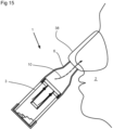
- FIG 15 the application of the respiratory therapy device 1 for nasal use is shown.
- the mouthpiece 6 of the respiratory therapy device opens into a mask 38, which is placed in the usual and known manner on the outside of the nose of the patient 20.
- the patient 20 can therefore also use the respiratory therapy device 1 according to the invention for the mucus solution within the nasal cavity.
- the tongues 15 can be made of a flexible material. It is crucial that the tongues 15 vibrate and thus generate the acoustically perceptible vibration of their oscillation. Consequently, the material used can consist of metal, a hard plastic or a fabric made of these materials.
Landscapes
- Health & Medical Sciences (AREA)
- General Health & Medical Sciences (AREA)
- Life Sciences & Earth Sciences (AREA)
- Pulmonology (AREA)
- Engineering & Computer Science (AREA)
- Public Health (AREA)
- Emergency Medicine (AREA)
- Veterinary Medicine (AREA)
- Animal Behavior & Ethology (AREA)
- Anesthesiology (AREA)
- Biomedical Technology (AREA)
- Heart & Thoracic Surgery (AREA)
- Hematology (AREA)
- Biophysics (AREA)
- Physical Education & Sports Medicine (AREA)
- Orthopedic Medicine & Surgery (AREA)
- Percussion Or Vibration Massage (AREA)
- Orthopedics, Nursing, And Contraception (AREA)
Claims (7)
- Un appareil de thérapie respiratoire (1) pour traiter les muscles des voies respiratoires, les fonctions pulmonaires et/ou les dépôts de mucus dans les poumons, le nez et/ou la gorge d'un patient (2), composé de :- un corps creux (3) dans lequel au moins un canal de passage (4, 5) est prévu,- un embout buccal ou nasal (6) inséré dans le corps creux (3) et relié au patient (2) pendant la durée du traitement par l'appareil de thérapie respiratoire (1),- et au moins un corps oscillant (11, 12) situé à l'intérieur du corps creux (3) et soumis à une vibration oscillante par l'inspiration et/ou l'expiration du patient (2),dans lequel un corps de retenue (13) dans lequel au moins une ouverture (14) est incorporée est inséré dans le corps creux (3), dans lequel une languette librement oscillante (15) pour générer des oscillations, qui sont acoustiquement perceptibles par l'oreille humaine et qui, en raison de leur fréquence différente, permettent de distinguer l'inspiration de l'expiration, est fixée au corps de retenue (13) dans la zone de l'ouverture (14), au moyen de laquelle l'ouverture (14) du corps de retenue (13) est fermée ou partiellement ouverte en fonction des flux d'air (7, 8) régnant à l'intérieur du corps creux (3), la face d'extrémité (9) du corps creux (3) opposée à l'embout buccal (6) étant ouverte, dans laquelle une sténose (18) est insérée dans cette face d'extrémité (9), au moins deux ouvertures de passage (20) étant prévues dans la surface latérale (19) de ladite sténose, à travers lesquelles les flux d'air (7, 8) s'écoulent vers l'intérieur du corps creux (3) ou, à l'inverse, s'en échappent, dans laquelle les ouvertures (20) de la sténose (18) ont des sections transversales différentes en tant que passages d'air pour les flux d'air (7, 8) et dans laquelle la sténose (18) est montée rotative dans le corps creux (3) de manière à ce que l'une des ouvertures (20) puisse être sélectionnée ou ajustée en tant que passage d'air en faisant tourner la sténose (18).
- L'appareil de thérapie respiratoire selon la revendication 1, dans lequel la sténose (18) possède une paroi (21) par laquelle l'accès au corps creux (3) dans la direction de son axe de symétrie (3') est fermé, et dans lequel le contour extérieur de la sténose (18) est adapté au contour intérieur du corps creux (3).
- L'appareil de thérapie respiratoire selon l'une des revendications 1 ou 2, dans lequel les ouvertures de passage (20) peuvent être fermées au moyen d'un bouchon (23).
- L'appareil de thérapie respiratoire selon l'une des revendications précédentes, dans lequel la languette (15) repose sur la surface du corps creux (13) ou se soulève d'un côté de celle-ci, ou dans lequel la languette (15) permet à l'air d'entrer et/ou de sortir par l'ouverture (14) de manière oscillante.
- L'appareil de thérapie respiratoire selon l'une des revendications précédentes, dans lequel un premier et un second corps oscillant (11, 12) sont disposés dans une direction respiratoire et/ou dans la direction respiratoire opposée.
- L'appareil de thérapie respiratoire selon l'une des revendications précédentes, dans lequel le corps creux (13) est conçu comme un profilé de boîte qui enferme une cavité de façon cubique, dans lequel un capteur (24) et/ou un microphone (25) est connecté à au moins un des corps oscillants (11, 12), dans lequel des signaux acoustiques ou électriques sont transmis à un appareil externe (26), des signaux acoustiques ou électriques sont transmis à un appareil externe (26), les corps oscillants (11, 12) servant de corps sonores acoustiquement perceptibles pour vérifier l'utilisation correcte ou souhaitée de l'appareil de thérapie respiratoire (1), et les ouvertures étant prévues sur une face frontale du boîtier, parallèlement aux valves.
- L'appareil de thérapie respiratoire selon l'une des revendications précédentes, dans lequel la languette (15) est faite d'un matériau flexible, de préférence en métal, en plastique dur ou en tissu fait de ces matériaux.
Applications Claiming Priority (2)
| Application Number | Priority Date | Filing Date | Title |
|---|---|---|---|
| EP20190395.2A EP3954418A1 (fr) | 2020-08-11 | 2020-08-11 | Appareil de thérapie respiratoire |
| PCT/EP2021/061531 WO2022033734A1 (fr) | 2020-08-11 | 2021-05-03 | Instrument de thérapie respiratoire |
Publications (3)
| Publication Number | Publication Date |
|---|---|
| EP4175703A1 EP4175703A1 (fr) | 2023-05-10 |
| EP4175703C0 EP4175703C0 (fr) | 2024-10-02 |
| EP4175703B1 true EP4175703B1 (fr) | 2024-10-02 |
Family
ID=72193256
Family Applications (2)
| Application Number | Title | Priority Date | Filing Date |
|---|---|---|---|
| EP20190395.2A Withdrawn EP3954418A1 (fr) | 2020-08-11 | 2020-08-11 | Appareil de thérapie respiratoire |
| EP21722237.1A Active EP4175703B1 (fr) | 2020-08-11 | 2021-05-03 | Appareil de thérapie respiratoire |
Family Applications Before (1)
| Application Number | Title | Priority Date | Filing Date |
|---|---|---|---|
| EP20190395.2A Withdrawn EP3954418A1 (fr) | 2020-08-11 | 2020-08-11 | Appareil de thérapie respiratoire |
Country Status (8)
| Country | Link |
|---|---|
| US (1) | US20230321375A1 (fr) |
| EP (2) | EP3954418A1 (fr) |
| CN (1) | CN116096449B (fr) |
| AU (1) | AU2021325277B2 (fr) |
| CA (1) | CA3191693A1 (fr) |
| ES (1) | ES2994975T3 (fr) |
| PL (1) | PL4175703T3 (fr) |
| WO (1) | WO2022033734A1 (fr) |
Families Citing this family (6)
| Publication number | Priority date | Publication date | Assignee | Title |
|---|---|---|---|---|
| US12403356B2 (en) * | 2020-08-06 | 2025-09-02 | Duke University | Voice therapy device and system |
| KR102416723B1 (ko) * | 2020-10-20 | 2022-07-06 | (주)지에이치이노텍 | 호흡근 강화기기 |
| IT202100012089A1 (it) * | 2021-05-11 | 2022-11-11 | Milano Politecnico | Dispositivo per l’analisi/monitoraggio e l’allenamento del sistema respiratorio |
| US12350551B2 (en) * | 2022-09-16 | 2025-07-08 | Mitsuko and Masako, LLC | Mouth insert for one-way breathing |
| US20250001123A1 (en) * | 2023-06-30 | 2025-01-02 | Berendo Scientific, LLC | Breathing exercise apparatuses |
| CN116899186B (zh) * | 2023-08-22 | 2026-01-23 | 北京仰生恒泰科技有限责任公司 | 一种防护型呼吸训练装置 |
Citations (1)
| Publication number | Priority date | Publication date | Assignee | Title |
|---|---|---|---|---|
| EP0262239B1 (fr) * | 1986-09-29 | 1992-12-30 | Brugger, Stephan, Dipl.-Wirt.-Ing. | Dispositif respiratoire |
Family Cites Families (16)
| Publication number | Priority date | Publication date | Assignee | Title |
|---|---|---|---|---|
| US4054134A (en) * | 1975-09-15 | 1977-10-18 | Kritzer Richard W | Respirators |
| CH685475A5 (fr) * | 1992-04-10 | 1995-07-31 | Varioraw Percutive Sa | Appareil thérapeutique spécifique du domaine respiratoire. |
| CN1178477A (zh) * | 1995-02-10 | 1998-04-08 | 埃弗里特·D·霍根 | 便携式个人用呼吸装置 |
| EP1272243B1 (fr) * | 2000-04-11 | 2005-10-26 | Trudell Medical International | Appareil aerosol avec une capacite de pression expiratoire positive |
| US11452838B2 (en) * | 2011-04-28 | 2022-09-27 | Michael J. Rusher | Positive expiratory pressure devices with flutter valve |
| AU2012334820B2 (en) * | 2011-11-11 | 2014-12-18 | ResMed Pty Ltd | Exchanger assembly for respiratory treatment |
| US20140166004A1 (en) * | 2012-12-19 | 2014-06-19 | Carefusion 303, Inc. | Nebulizer with integrated breathing incentive |
| GB201310824D0 (en) * | 2013-06-18 | 2013-07-31 | Smiths Medical Int Ltd | Respiratory therapy apparatus and methods |
| US10004872B1 (en) * | 2015-03-06 | 2018-06-26 | D R Burton Healthcare, Llc | Positive expiratory pressure device having an oscillating valve |
| ES2855373T3 (es) * | 2015-12-04 | 2021-09-23 | Trudell Medical Int | Dispositivo de simulación de tos por espiración forzada |
| EP3251718B1 (fr) | 2016-06-01 | 2018-08-15 | R. Cegla GmbH & Co. KG | Appareil de soins respiratoires |
| WO2019070804A1 (fr) * | 2017-10-03 | 2019-04-11 | Yasi's, Llc | Thérapie respiratoire |
| US11666801B2 (en) * | 2018-01-04 | 2023-06-06 | Trudell Medical International | Smart oscillating positive expiratory pressure device |
| DE102018120533A1 (de) | 2018-08-23 | 2020-02-27 | R. Cegla Gmbh & Co. Kg | Beatmungs-Vorrichtung |
| CN210125154U (zh) * | 2019-05-05 | 2020-03-06 | 南通市肺科医院(南通市第六人民医院) | 一种用于呼吸内科的肺功能恢复训练器 |
| CN110960835A (zh) * | 2019-12-10 | 2020-04-07 | 施琴朗 | 一种智能呼吸训练器及其监测方法 |
-
2020
- 2020-08-11 EP EP20190395.2A patent/EP3954418A1/fr not_active Withdrawn
-
2021
- 2021-05-03 WO PCT/EP2021/061531 patent/WO2022033734A1/fr not_active Ceased
- 2021-05-03 CA CA3191693A patent/CA3191693A1/fr active Pending
- 2021-05-03 US US18/021,056 patent/US20230321375A1/en active Pending
- 2021-05-03 EP EP21722237.1A patent/EP4175703B1/fr active Active
- 2021-05-03 ES ES21722237T patent/ES2994975T3/es active Active
- 2021-05-03 PL PL21722237.1T patent/PL4175703T3/pl unknown
- 2021-05-03 CN CN202180056108.0A patent/CN116096449B/zh active Active
- 2021-05-03 AU AU2021325277A patent/AU2021325277B2/en active Active
Patent Citations (1)
| Publication number | Priority date | Publication date | Assignee | Title |
|---|---|---|---|---|
| EP0262239B1 (fr) * | 1986-09-29 | 1992-12-30 | Brugger, Stephan, Dipl.-Wirt.-Ing. | Dispositif respiratoire |
Also Published As
| Publication number | Publication date |
|---|---|
| PL4175703T3 (pl) | 2025-04-14 |
| CN116096449A (zh) | 2023-05-09 |
| CN116096449B (zh) | 2026-01-09 |
| AU2021325277A1 (en) | 2023-03-23 |
| EP4175703C0 (fr) | 2024-10-02 |
| AU2021325277B2 (en) | 2024-05-02 |
| WO2022033734A1 (fr) | 2022-02-17 |
| EP3954418A1 (fr) | 2022-02-16 |
| EP4175703A1 (fr) | 2023-05-10 |
| ES2994975T3 (en) | 2025-02-05 |
| US20230321375A1 (en) | 2023-10-12 |
| CA3191693A1 (fr) | 2022-02-17 |
Similar Documents
| Publication | Publication Date | Title |
|---|---|---|
| EP4175703B1 (fr) | Appareil de thérapie respiratoire | |
| DE60035328T2 (de) | Vorrichtung zum Aufrechterhalten eines positiven Ausatmungsdruckes | |
| DE60027372T2 (de) | Vorrichtung zur Atmungsunterstützung | |
| EP2087927B1 (fr) | Appareil de thérapie | |
| DE69636751T2 (de) | Tragbares und persönliches beatmungsgerät | |
| DE69523657T2 (de) | Vorrichtung zum Aufrechterhalten eines positiven Ausatemdruckes | |
| DE60111061T2 (de) | Durchflussregelungsventil für eine handbetätigte wiederbelebungsvorrichtung | |
| DE60025443T2 (de) | Therapiegerät zur Erzeugung eines kontinuierlichen positiven Atemwegdruckes | |
| EP0681853B1 (fr) | Appareil thérapeutique respiratoire | |
| DE69737833T2 (de) | Kompaktes lungenübungsgerät | |
| EP2903672B1 (fr) | Système, procédé et utilisation aux fins d'entraînement à une opération d'inhalation | |
| CH660975A5 (de) | Beatmungsgeraet. | |
| DE212011100071U1 (de) | Trachealkupplungen und zugehörige Systeme | |
| DE10337138A1 (de) | Verfahren und Anordnung zur Atmungsunterstützung eines Patienten sowie Luftröhrenprothese und Katheter | |
| DE102008028662A1 (de) | Vorrichtung und Verfahren zum Monitoring bei einer manuellen Beatmung | |
| DE102007017783B4 (de) | Therapiegerät | |
| DE102004019122A1 (de) | Verfahren zur Steuerung eines Beatmungsgerätes und Anlage hierfür | |
| EP2978508A1 (fr) | Appareil thérapeutique pour le traitement de maladies des voies respiratoires | |
| DE102006032620B3 (de) | Beatmungsgerät zur Behandlung von obstruktiver Schlafapnoe und Verfahren zu dessen Steuerung | |
| EP3620195B1 (fr) | Dispositif de respiration | |
| EP3484562A1 (fr) | Unité de nébulisation à embout remplaçable | |
| EP1935446B1 (fr) | Dispositif et procédé d'administration d'oxygène dans le cadre d'une réanimation | |
| DE202004010382U1 (de) | Ventiltechnische Vorrichtung zur Nachbildung der natürlichen Atemwegsfunktionen | |
| EP3251718A1 (fr) | Appareil de soins respiratoires | |
| DE102004011078B4 (de) | Atemgerät |
Legal Events
| Date | Code | Title | Description |
|---|---|---|---|
| STAA | Information on the status of an ep patent application or granted ep patent |
Free format text: STATUS: UNKNOWN |
|
| STAA | Information on the status of an ep patent application or granted ep patent |
Free format text: STATUS: THE INTERNATIONAL PUBLICATION HAS BEEN MADE |
|
| PUAI | Public reference made under article 153(3) epc to a published international application that has entered the european phase |
Free format text: ORIGINAL CODE: 0009012 |
|
| STAA | Information on the status of an ep patent application or granted ep patent |
Free format text: STATUS: REQUEST FOR EXAMINATION WAS MADE |
|
| 17P | Request for examination filed |
Effective date: 20230131 |
|
| AK | Designated contracting states |
Kind code of ref document: A1 Designated state(s): AL AT BE BG CH CY CZ DE DK EE ES FI FR GB GR HR HU IE IS IT LI LT LU LV MC MK MT NL NO PL PT RO RS SE SI SK SM TR |
|
| RAP1 | Party data changed (applicant data changed or rights of an application transferred) |
Owner name: CEGLA MEDIZINTECHNIK GMBH |
|
| DAV | Request for validation of the european patent (deleted) | ||
| DAX | Request for extension of the european patent (deleted) | ||
| STAA | Information on the status of an ep patent application or granted ep patent |
Free format text: STATUS: EXAMINATION IS IN PROGRESS |
|
| 17Q | First examination report despatched |
Effective date: 20231214 |
|
| REG | Reference to a national code |
Ref country code: DE Ref legal event code: R079 Free format text: PREVIOUS MAIN CLASS: A61M0016000000 Ipc: A63B0021000000 Ref country code: DE Ref legal event code: R079 Ref document number: 502021005321 Country of ref document: DE Free format text: PREVIOUS MAIN CLASS: A61M0016000000 Ipc: A63B0021000000 |
|
| GRAP | Despatch of communication of intention to grant a patent |
Free format text: ORIGINAL CODE: EPIDOSNIGR1 |
|
| STAA | Information on the status of an ep patent application or granted ep patent |
Free format text: STATUS: GRANT OF PATENT IS INTENDED |
|
| RIC1 | Information provided on ipc code assigned before grant |
Ipc: A63B 71/06 20060101ALI20240517BHEP Ipc: A61M 16/08 20060101ALI20240517BHEP Ipc: A61M 16/20 20060101ALI20240517BHEP Ipc: A61M 16/00 20060101ALI20240517BHEP Ipc: A63B 23/18 20060101ALI20240517BHEP Ipc: A63B 21/00 20060101AFI20240517BHEP |
|
| INTG | Intention to grant announced |
Effective date: 20240620 |
|
| GRAS | Grant fee paid |
Free format text: ORIGINAL CODE: EPIDOSNIGR3 |
|
| GRAA | (expected) grant |
Free format text: ORIGINAL CODE: 0009210 |
|
| STAA | Information on the status of an ep patent application or granted ep patent |
Free format text: STATUS: THE PATENT HAS BEEN GRANTED |
|
| AK | Designated contracting states |
Kind code of ref document: B1 Designated state(s): AL AT BE BG CH CY CZ DE DK EE ES FI FR GB GR HR HU IE IS IT LI LT LU LV MC MK MT NL NO PL PT RO RS SE SI SK SM TR |
|
| REG | Reference to a national code |
Ref country code: GB Ref legal event code: FG4D Free format text: NOT ENGLISH |
|
| REG | Reference to a national code |
Ref country code: CH Ref legal event code: EP |
|
| REG | Reference to a national code |
Ref country code: DE Ref legal event code: R096 Ref document number: 502021005321 Country of ref document: DE |
|
| REG | Reference to a national code |
Ref country code: IE Ref legal event code: FG4D Free format text: LANGUAGE OF EP DOCUMENT: GERMAN |
|
| U01 | Request for unitary effect filed |
Effective date: 20241016 |
|
| U07 | Unitary effect registered |
Designated state(s): AT BE BG DE DK EE FI FR IT LT LU LV MT NL PT RO SE SI Effective date: 20241104 |
|
| REG | Reference to a national code |
Ref country code: ES Ref legal event code: FG2A Ref document number: 2994975 Country of ref document: ES Kind code of ref document: T3 Effective date: 20250205 |
|
| PG25 | Lapsed in a contracting state [announced via postgrant information from national office to epo] |
Ref country code: IS Free format text: LAPSE BECAUSE OF FAILURE TO SUBMIT A TRANSLATION OF THE DESCRIPTION OR TO PAY THE FEE WITHIN THE PRESCRIBED TIME-LIMIT Effective date: 20250202 Ref country code: HR Free format text: LAPSE BECAUSE OF FAILURE TO SUBMIT A TRANSLATION OF THE DESCRIPTION OR TO PAY THE FEE WITHIN THE PRESCRIBED TIME-LIMIT Effective date: 20241002 |
|
| PG25 | Lapsed in a contracting state [announced via postgrant information from national office to epo] |
Ref country code: NO Free format text: LAPSE BECAUSE OF FAILURE TO SUBMIT A TRANSLATION OF THE DESCRIPTION OR TO PAY THE FEE WITHIN THE PRESCRIBED TIME-LIMIT Effective date: 20250102 |
|
| PG25 | Lapsed in a contracting state [announced via postgrant information from national office to epo] |
Ref country code: GR Free format text: LAPSE BECAUSE OF FAILURE TO SUBMIT A TRANSLATION OF THE DESCRIPTION OR TO PAY THE FEE WITHIN THE PRESCRIBED TIME-LIMIT Effective date: 20250103 |
|
| PG25 | Lapsed in a contracting state [announced via postgrant information from national office to epo] |
Ref country code: CZ Free format text: LAPSE BECAUSE OF FAILURE TO SUBMIT A TRANSLATION OF THE DESCRIPTION OR TO PAY THE FEE WITHIN THE PRESCRIBED TIME-LIMIT Effective date: 20241002 |
|
| PG25 | Lapsed in a contracting state [announced via postgrant information from national office to epo] |
Ref country code: RS Free format text: LAPSE BECAUSE OF FAILURE TO SUBMIT A TRANSLATION OF THE DESCRIPTION OR TO PAY THE FEE WITHIN THE PRESCRIBED TIME-LIMIT Effective date: 20250102 |
|
| U20 | Renewal fee for the european patent with unitary effect paid |
Year of fee payment: 5 Effective date: 20250516 |
|
| PG25 | Lapsed in a contracting state [announced via postgrant information from national office to epo] |
Ref country code: SM Free format text: LAPSE BECAUSE OF FAILURE TO SUBMIT A TRANSLATION OF THE DESCRIPTION OR TO PAY THE FEE WITHIN THE PRESCRIBED TIME-LIMIT Effective date: 20241002 |
|
| PGFP | Annual fee paid to national office [announced via postgrant information from national office to epo] |
Ref country code: PL Payment date: 20250417 Year of fee payment: 5 |
|
| PGFP | Annual fee paid to national office [announced via postgrant information from national office to epo] |
Ref country code: ES Payment date: 20250616 Year of fee payment: 5 |
|
| PGFP | Annual fee paid to national office [announced via postgrant information from national office to epo] |
Ref country code: CH Payment date: 20250601 Year of fee payment: 5 |
|
| PG25 | Lapsed in a contracting state [announced via postgrant information from national office to epo] |
Ref country code: SK Free format text: LAPSE BECAUSE OF FAILURE TO SUBMIT A TRANSLATION OF THE DESCRIPTION OR TO PAY THE FEE WITHIN THE PRESCRIBED TIME-LIMIT Effective date: 20241002 |
|
| PGFP | Annual fee paid to national office [announced via postgrant information from national office to epo] |
Ref country code: TR Payment date: 20250425 Year of fee payment: 5 |
|
| PLBE | No opposition filed within time limit |
Free format text: ORIGINAL CODE: 0009261 |
|
| STAA | Information on the status of an ep patent application or granted ep patent |
Free format text: STATUS: NO OPPOSITION FILED WITHIN TIME LIMIT |
|
| 26N | No opposition filed |
Effective date: 20250703 |
|
| PG25 | Lapsed in a contracting state [announced via postgrant information from national office to epo] |
Ref country code: MC Free format text: LAPSE BECAUSE OF FAILURE TO SUBMIT A TRANSLATION OF THE DESCRIPTION OR TO PAY THE FEE WITHIN THE PRESCRIBED TIME-LIMIT Effective date: 20241002 |
|
| PGFP | Annual fee paid to national office [announced via postgrant information from national office to epo] |
Ref country code: GB Payment date: 20260324 Year of fee payment: 6 |
|
| PG25 | Lapsed in a contracting state [announced via postgrant information from national office to epo] |
Ref country code: IE Free format text: LAPSE BECAUSE OF NON-PAYMENT OF DUE FEES Effective date: 20250503 |