EP4176172B1 - Turbine à aubes dynamiques - Google Patents
Turbine à aubes dynamiques Download PDFInfo
- Publication number
- EP4176172B1 EP4176172B1 EP21742584.2A EP21742584A EP4176172B1 EP 4176172 B1 EP4176172 B1 EP 4176172B1 EP 21742584 A EP21742584 A EP 21742584A EP 4176172 B1 EP4176172 B1 EP 4176172B1
- Authority
- EP
- European Patent Office
- Prior art keywords
- swing arm
- blade
- turbine
- support wheel
- stream
- Prior art date
- Legal status (The legal status is an assumption and is not a legal conclusion. Google has not performed a legal analysis and makes no representation as to the accuracy of the status listed.)
- Active
Links
Images





Classifications
-
- F—MECHANICAL ENGINEERING; LIGHTING; HEATING; WEAPONS; BLASTING
- F03—MACHINES OR ENGINES FOR LIQUIDS; WIND, SPRING, OR WEIGHT MOTORS; PRODUCING MECHANICAL POWER OR A REACTIVE PROPULSIVE THRUST, NOT OTHERWISE PROVIDED FOR
- F03B—MACHINES OR ENGINES FOR LIQUIDS
- F03B17/00—Other machines or engines
- F03B17/06—Other machines or engines using liquid flow with predominantly kinetic energy conversion, e.g. of swinging-flap type, "run-of-river", "ultra-low head"
- F03B17/062—Other machines or engines using liquid flow with predominantly kinetic energy conversion, e.g. of swinging-flap type, "run-of-river", "ultra-low head" with rotation axis substantially at right angle to flow direction
- F03B17/065—Other machines or engines using liquid flow with predominantly kinetic energy conversion, e.g. of swinging-flap type, "run-of-river", "ultra-low head" with rotation axis substantially at right angle to flow direction the flow engaging parts having a cyclic movement relative to the rotor during its rotation
- F03B17/067—Other machines or engines using liquid flow with predominantly kinetic energy conversion, e.g. of swinging-flap type, "run-of-river", "ultra-low head" with rotation axis substantially at right angle to flow direction the flow engaging parts having a cyclic movement relative to the rotor during its rotation the cyclic relative movement being positively coupled to the movement of rotation
-
- F—MECHANICAL ENGINEERING; LIGHTING; HEATING; WEAPONS; BLASTING
- F03—MACHINES OR ENGINES FOR LIQUIDS; WIND, SPRING, OR WEIGHT MOTORS; PRODUCING MECHANICAL POWER OR A REACTIVE PROPULSIVE THRUST, NOT OTHERWISE PROVIDED FOR
- F03B—MACHINES OR ENGINES FOR LIQUIDS
- F03B13/00—Adaptations of machines or engines for special use; Combinations of machines or engines with driving or driven apparatus; Power stations or aggregates
- F03B13/12—Adaptations of machines or engines for special use; Combinations of machines or engines with driving or driven apparatus; Power stations or aggregates characterised by using wave or tide energy
- F03B13/26—Adaptations of machines or engines for special use; Combinations of machines or engines with driving or driven apparatus; Power stations or aggregates characterised by using wave or tide energy using tide energy
- F03B13/264—Adaptations of machines or engines for special use; Combinations of machines or engines with driving or driven apparatus; Power stations or aggregates characterised by using wave or tide energy using tide energy using the horizontal flow of water resulting from tide movement
-
- F—MECHANICAL ENGINEERING; LIGHTING; HEATING; WEAPONS; BLASTING
- F05—INDEXING SCHEMES RELATING TO ENGINES OR PUMPS IN VARIOUS SUBCLASSES OF CLASSES F01-F04
- F05B—INDEXING SCHEME RELATING TO WIND, SPRING, WEIGHT, INERTIA OR LIKE MOTORS, TO MACHINES OR ENGINES FOR LIQUIDS COVERED BY SUBCLASSES F03B, F03D AND F03G
- F05B2240/00—Components
- F05B2240/20—Rotors
- F05B2240/30—Characteristics of rotor blades, i.e. of any element transforming dynamic fluid energy to or from rotational energy and being attached to a rotor
-
- F—MECHANICAL ENGINEERING; LIGHTING; HEATING; WEAPONS; BLASTING
- F05—INDEXING SCHEMES RELATING TO ENGINES OR PUMPS IN VARIOUS SUBCLASSES OF CLASSES F01-F04
- F05B—INDEXING SCHEME RELATING TO WIND, SPRING, WEIGHT, INERTIA OR LIKE MOTORS, TO MACHINES OR ENGINES FOR LIQUIDS COVERED BY SUBCLASSES F03B, F03D AND F03G
- F05B2250/00—Geometry
- F05B2250/70—Shape
- F05B2250/72—Shape symmetric
-
- F—MECHANICAL ENGINEERING; LIGHTING; HEATING; WEAPONS; BLASTING
- F05—INDEXING SCHEMES RELATING TO ENGINES OR PUMPS IN VARIOUS SUBCLASSES OF CLASSES F01-F04
- F05B—INDEXING SCHEME RELATING TO WIND, SPRING, WEIGHT, INERTIA OR LIKE MOTORS, TO MACHINES OR ENGINES FOR LIQUIDS COVERED BY SUBCLASSES F03B, F03D AND F03G
- F05B2260/00—Function
- F05B2260/50—Kinematic linkage, i.e. transmission of position
- F05B2260/505—Kinematic linkage, i.e. transmission of position using chains and sprockets; using toothed belts
-
- Y—GENERAL TAGGING OF NEW TECHNOLOGICAL DEVELOPMENTS; GENERAL TAGGING OF CROSS-SECTIONAL TECHNOLOGIES SPANNING OVER SEVERAL SECTIONS OF THE IPC; TECHNICAL SUBJECTS COVERED BY FORMER USPC CROSS-REFERENCE ART COLLECTIONS [XRACs] AND DIGESTS
- Y02—TECHNOLOGIES OR APPLICATIONS FOR MITIGATION OR ADAPTATION AGAINST CLIMATE CHANGE
- Y02E—REDUCTION OF GREENHOUSE GAS [GHG] EMISSIONS, RELATED TO ENERGY GENERATION, TRANSMISSION OR DISTRIBUTION
- Y02E10/00—Energy generation through renewable energy sources
- Y02E10/30—Energy from the sea, e.g. using wave energy or salinity gradient
Definitions
- the present invention relates to turbine designs and methods of operation for capturing energy from a flowing stream.
- it relates to turbines with adjustable blades that are uniquely adjusted as the turbine wheel rotates for improved energy capture in low and zero head applications such as tidal streams.
- CN104564486 discloses a waterwheel power generation device using chains to allow waterwheel blades to be synchronously vertical.
- the device comprises a waterwheel with a plurality of blades, an acceleration gear box, and a power generation unit.
- the waterwheel power generation device has the advantages that the blades are mounted on the waterwheel in a way that the blades are vertical to a flowing water plane, the blades can be driven under the impacts of the flowing water, and the blades are allowed to be constantly vertical to the flowing water plane.
- DE10134522 describes an undershot water wheel which has first blades, adjustment elements for adjusting the angular settings depending on the current rotation angle of the water wheel and a controller for the adjustment elements. Second blades with a smaller radial dimension arranged between the first blades likewise have adjustment elements for adjustment of their angular setting with the water wheel rotation angle.
- US2012262036 discloses a waterwheel that is provided to embody as a modularly constructed system for generating power via generators with transversely extending water blades as hinged or folding blades. In this regard it is provided to arrange the water blades over a truss framework.
- TW200406541 discloses an improvement to a conventional water turbine comprising blades of fixed length in which, when the water turbine is in rotation, torques caused by the weight of the blades exactly cancel each other so that the driving force of the water turbine is provided by the blades driven by water flows only.
- the improvement provided a water turbine device, which is characterized by comprising length-adjustable blades.
- EP2857674 discloses a variable blade type tidal and wind power generator with increased generation efficiency.
- DE 102008003764 discloses a polygon-shaped wind- and water rotor for power generation, which has movable surfaces standing away from vertical rotor in forward-running region, where attainable torque of rotor is higher compared to vertical rotor with rigid surfaces.
- a feature of the invention is a reduction in the downstream drift in the turbine blades during operation (i.e. a reduction in the horizontal distance travelled by the blades when dipped in the stream). Accordingly, energy capture and efficiency can be improved.
- a turbine of the invention is designed for undershot applications and comprises a frame, a wheel assembly, a plurality of swing arm assemblies with attached blades, and a timing assembly for controlling the rotation of the swing arms and attached blades.
- the wheel assembly comprises a horizontal wheel axle and a support wheel having a centre and a circumference in which the wheel axle is located at the centre of the support wheel.
- the support wheel is rotatably mounted with respect to the frame and this can either involve suitable arrangements in which the support wheel is directly attached to the wheel axle (and hence both rotate with respect to the frame) or in which the support wheel is not directly attached to the wheel axle (and in which only the support wheel rotates with respect to the frame).
- Each of the plurality of swing arm assemblies in the turbine comprises a horizontal swing arm shaft, a swing arm, and a blade.
- the swing arm shaft is located at the circumference of the support wheel.
- the swing arm has two ends, namely an axle end and a blade end.
- the swing arm shaft is located at the axle end of the swing arm and the blade is attached to the blade end of the swing arm. Further, the swing arm is rotatably mounted with respect to the support wheel.
- the timing assembly is configured to control the rotation of each swing arm with attached blade such that, as the support wheel rotates, each swing arm with attached blade rotates counter to the direction of rotation of the support wheel. Further it is configured such that each swing arm with attached blade completes one full revolution for every full revolution of the support wheel and such that each blade is i) rotated inboard of its respective swing arm shaft before it enters the stream, ii) then rotated outboard of its respective swing arm shaft as it passes through the stream, and iii) then rotated inboard of its respective swing arm shaft before it exits the stream.
- the timing assembly can be configured to control the rotation of each swing arm with attached blade such that each blade is essentially horizontal when its respective swing arm shaft is at its lowest or highest point with respect to the stream and essentially vertical when its respective swing arm shaft is midway between its lowest and highest points with respect to the stream.
- the timing assembly is configured such that the plurality of swing arms with attached blades rotate in synchrony at a constant rate.
- the timing assembly can instead be configured to advance or retard the rotation of each of the swing arms with attached blades as the support wheel rotates (e.g. up to about 20 degrees in rotation).
- Suitable timing assemblies for use in the invention can be quite simple mechanically (e.g. comprising a set of sprockets for each of the swing arms with attached blades, a stationary sprocket around the wheel axle, and a drive chain system interconnecting each of the set of sprockets and the stationary sprocket) or alternatively more complex for more complex control of the individual swing arm assemblies (e.g. comprising more complex mechanical designs and/or including pneumatically or hydraulically operated mechanisms).
- Exemplary embodiments of such turbines may preferably comprise greater than or equal to three swing arm assemblies.
- a variety of shapes may be employed for the blades.
- the blades may simply be flat but as another option, the profile of each of the blades may be shaped to match the swing arm radius (i.e. wherein the distance between each of the blade centres and the swing arm shafts is what defines the "swing arm radius"). Yet other blade shape options may be considered.
- Desirable embodiments of the invention are characterized by significant reduction in the downstream drift of the turbine blades when compared to conventional waterwheels and the like.
- the distance between each of the swing arm shafts and the wheel axle is used to define a "support wheel radius” and the distance between each of the blade centres and the swing arm shafts defines "a swing arm radius”
- an example of turbine showing a significant reduction in downstream drift is one in which the ratio of the swing arm radius/support wheel radius is greater than or about 0.33, and particularly in which this ratio is greater than or about 0.67.
- an increased amount of energy can be captured from the surface of a flowing stream by obtaining the aforementioned turbine, dipping the turbine into the stream to an appropriate dip depth, allowing the support wheel to rotate at a wheel velocity and thus capturing energy from the rotating support wheel.
- the turbine may be dipped into the flowing stream to depths greater than those considered appropriate for conventional waterwheels and thereby obtain greater energy capture from the stream. For instance, the turbine maybe dipped to depths up to 90% or even potentially 100% of the support wheel radius.
- essentially vertical and essentially horizontal are to be construed as including orientations of turbine blades that are actually vertical and horizontal respectively but also approximately so if such approximate orientations do not materially affect the characteristics and results associated with the invention.
- blade orientations would be considered to be essentially vertical or horizontal if they were angled at or within a few degrees of true vertical or horizontal respectively.
- definitions of vertical and horizontal are themselves required.
- the vertical and horizontal with respect to a given blade refers to those directions taken at the centre of that blade and perpendicular to the orientation of that blade's associated swing arm.
- inboard and outboard refer to positions of a given blade with respect to its associated swing arm shaft and the wheel axle of the wheel assembly. Specifically, a blade is considered to be inboard when its centre is positioned closer to the wheel axle of the wheel assembly than its associated swing arm shaft is. A blade is considered to be outboard when its centre is positioned farther from the wheel axle of the wheel assembly than its associated swing arm shaft is.
- support wheel radius is defined as the distance between each of the swing arm shafts and the wheel axle.
- swing arm radius is defined as the distance between each of the blade centres and the swing arm shafts.
- turbine designs and operating methods are disclosed for improved energy capture in undershot applications. With these, higher rotation rates and greater dip depths can be obtained when compared to conventional waterwheels.
- the turbine comprises a plurality of dynamically adjusted blades which are driven by both drag and lift forces provided from a horizontally flowing stream. These designs allow for a desirable reduction in the downstream drift of the turbine blades and also cleaner entry and exit of the turbine blades during operation.
- Figures 1 through 5 are illustrative of exemplary embodiments of the invention.
- Figure 1 shows an isometric view of a simple exemplary turbine in a flowing tidal stream.
- undershot turbine 1 is shown dipped in flowing tidal stream 50 which is flowing in horizontal direction 50a.
- Turbine 1 comprises frame 3, wheel assembly 5, a plurality of swing arm assemblies 10, and timing assembly 20 (not visible in Figure 1 ).
- Wheel assembly 5 comprises horizontal wheel axle 6 and support wheel 7.
- Support wheel 7 has a centre 7a and circumference 7b.
- Support wheel 7 comprises two side supports 8a, 8b on opposite sides of wheel 7.
- Wheel axle 6 is located at centre 7a in between side supports 8a, 8b.
- wheel axle 6 is fixed to and thus remains stationary with respect to frame 3.
- Bushing and/or bearing assemblies are provided to allow support wheel 7 to rotate smoothly around wheel axle 6 (and hence also with respect to frame 3) in the direction shown by arrow 7c.
- the turbine 1 of Figure 1 has six swing arm assemblies 10 spaced around circumference 7b.
- Each swing arm assembly 10 comprises a horizontal swing arm shaft 11 located at circumference 7b, a pair of swing arms 12, and blade 13.
- Swing arms 12 each have an axle end 12a and blade end 12b.
- Swing arm shafts 11 are located between corresponding pairs of swing arms 12 at their axle ends 12a.
- Blades 13 are attached between corresponding pairs of swing arms 12 at their blade ends 12b.
- Each swing arm/blade unit 12/13 (comprising pair of swing arms 12 with attached blade 13) can rotate with respect to support wheel 7 around their respective swing arm shafts 11.
- timing assembly 20 controls the rotation of swing arm/blade unit 12/13.
- each swing arm/blade unit 12/13 rotates (shown by arrow 12c) counter to the direction of rotation of support wheel and completes one full revolution for every full revolution of support wheel 7. Further, rotation of each is controlled such that each blade 13 is: i) rotated inboard of its respective swing arm shaft 11 before it enters stream 50, ii) then rotated outboard of its respective swing arm shaft 11 as it passes through stream 50, and iii) then rotated inboard of its respective swing arm shaft 11 before it exits stream 50.
- a simple timing assembly 20 which controls each swing arm/blade unit 12/13 to rotate in synchrony at a constant rate.
- the orientations of swing arm/blade units 12/13 over a revolution of support wheel 7 are shown in detail in Figures 2a and 2b .
- side views of turbine 1 are shown on the side without timing assembly 20, namely on the side of side support 8a.
- swing arm shaft 11i of swing arm assembly 10i is shown starting at top dead centre in its rotation with support wheel 7. Opposite swing arm assembly 10i on support wheel 7 appears swing arm assembly 10iv with its swing arm shaft 11iv.
- swing arm shafts 11i and 11iv are passing through high and low points respectively over the rotation of support wheel 7. Blades 13i and 13iv of swing arm assemblies 10i and 10iv are both outboard of their respective swing arm shafts 11i and 11iv and both blades are oriented horizontally.
- Support wheel 7 continues to rotate in stream 50 and after half of a revolution of support wheel 7, swing arm/blade units 12/13 have been rotated such that their orientations are similar to those shown in Figure 2a but they are now instead located on opposite sides to those shown in Figure 2a (i.e. swing arm assemblies 12i and 12iv are now located where swing arm assemblies 12iv and 12i were in Figure 2a ).
- swing arm assemblies 12i and 12iv are now located where swing arm assemblies 12iv and 12i were in Figure 2a ).
- swing arm/blade units 12/13 have been rotated such that their orientations are similar to those shown in Figure 2b but again they are now instead located on opposite sides to those shown in Figure 2b (i.e.
- swing arm assemblies 12i and 12iv are now located where swing arm assemblies 12iv and 12i were in Figure 2b ). Finally, after one full revolution of support wheel 7, swing arm/blade units 12/13 have been rotated to return to the orientations and locations originally shown in Figure 2a .
- FIG. 1 shows a side view of the same turbine shown in Figure 2a except that the rotation of support wheel 7 and hence each of the swing arm/blade units 12/13 has been advanced by about 20° with respect to what is shown in Figure 2a .
- turbine 1 may be operated at greater dip depths in flowing stream 50. For instance, turbine 1 may be dipped to depths up to about 90% of the radius of support wheel 7. At such significant dip depths then, when blade 13i is at the location shown in Figure 2b , it is just at the point of entering stream 50. In a like manner, when blade 13iv is at the location shown in Figure 2b , it is just at the point of exiting stream 50. Consequently, each blade 13 in turbine 1 thus enters stream 50 essentially vertically and in a like manner, each blade 13 also exits stream 50 essentially vertically. Further, each blade 13 is essentially horizontal when their respective swing arm shafts 11 are at their highest and lowest points during rotation of support wheel 7 (as shown in Figure 2a ).
- FIG. 3a shows a side view of one suitable arrangement on the side of turbine 1 comprising timing assembly 20, namely support side 8b. Attached to each rotating swing arm blade unit 12/13 is respective sprocket 21 which is used to drive swing arm blade unit 12/13.
- sprocket 21i for swing arm/blade unit 12/13i is shown as a double sprocket for chain driving purposes.
- Idler sprocket 24 is also provided as shown to provide tension in drive chain 23b.
- the sprocket sizes of each sprocket 21, including sprocket 21i, in Figure 3a are all the same; i.e. the ratios are 1:1.
- Timing sprocket 22 however is twice the size of sprockets 21; i.e. ratio of timing sprocket 22 to each sprocket 21 is 2:1.
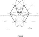
- Timing assembly 20 is shown in Figure 3b . Again, a side view on support side 8b is shown. Timing assembly 20 here is similar to that shown in Figure 3a except that a single chain 23b is used (chain 23a being omitted). Here though, two tensioning sprockets 24a and 24b are provided to engage chain 23b with timing sprocket 22, thereby interconnecting all sprockets 21 and timing sprocket 22.
- Figure 3c shows a view of a more sophisticated alternative timing assembly to that shown in Figure 3b which can now be used to advance or retard the rotation of the swing arm/blade units 12/13 to a limited extent with rotation of support wheel 7.
- the view shown in Figure 3c shows an enlarged view of only a portion of turbine 1 in the vicinity of centre 7a of support wheel 7. Thus, some elements appearing in Figure 3b are not visible here.
- stationary timing sprocket 22 is attached to frame 3 via adjustment arm 28 which allows for the orientation of stationary timing sprocket 22 to be adjusted to a certain extent with respect to flowing stream 50.
- Adjustment is accomplished by increasing or decreasing the length of adjustment arm 28 which is attached to frame 3 at end 28a and to either timing sprocket 22 or to support wheel 7 at end 28b.
- decreasing the length of adjustment arm 28 serves to advance the rotation of support wheel 7 and timing sprocket 22 while increasing the length serves to retard the rotation.
- the dashed line TDC is used represent the top dead centre position of Figure 2a for reference purposes.
- the dashed lines A and R then represent advanced and retarded orientations respectively with reference to TDC. (Those skilled in the art will appreciate that a similar adjustment arm arrangement may equally be applied to the embodiment shown in Figure 3a .)
- Figure 4 is provided to better visualize the definitions of support wheel radius and swing arm radius and also to show the paths of the centres of blades 13 and swing arm shafts 11 as support wheel 7 rotates.
- Figure 4 illustrates these from the perspective of support side 8a.
- Figure 4 is representative of an exemplary turbine similar to that of turbine 1 in which the relative ratio of swing arm radius to that of the wheel radius is about 0.77 and is to scale.
- Wheel axle 6 is shown at the centre of Figure 4 .
- the path of swing arm shafts 11 is denoted by path 30 (which also represents the location of circumference 7b of support wheel 7).
- path 31 The path of the centres of blades 13 is denoted by path 31.
- blade 13i is also shown in the orientation and location as it would appear if visible in Figure 2b .
- Segment WR thus illustrates the support wheel radius and segment AR illustrates the swing arm radius associated with blade 13i. Further in Figure 4 , the direction of rotation of support wheel 7 is shown by arrow 30c and the direction of rotation of blade 13i is shown by arrow 13c.
- path 31 of the blade centres is a markedly oval path.
- the ratio of the swing arm radius/support wheel radius can be greater than or about 0.33, and particularly greater than or about 0.67. The greater this ratio is, the more that downstream drift (represented by segment DD in Figure 4 ) is desirably reduced.
- the rotation rate of the support wheel (and hence blade tip velocity) is not defined by the downstream drift of the blades as with a conventional water wheel.
- the support wheel is able to rotate faster, with the speed at the support wheel circumference operating closer to unity with respect to the velocity of the flowing stream.
- a potential doubling of support wheel rotation rate as compared to that of a conventional water wheel (which is ⁇ 0.44 with respect to the stream) and support wheel circumference velocity (e.g. ⁇ 0.88 or greater with respect to the stream) may be achieved. Since the energy captured by a turbine is a function of this velocity squared, the additional energy captured by such a turbine may be expected to substantially increase because of the oval blade path and the doubling of the stream velocity interacting on the blades.
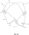
- Figures 5a and 5b illustrate aspects of flow associated with the exemplary inventive turbine of Figure 1 that are not experienced with conventional waterwheels and yet which may result in improved performance and efficiency.
- Figure 5a shows a momentary point in the rotation of the turbine of Figure 1 where stream flow to blade 13iii is adversely being affected by blade 13ii.
- Figure 5b shows a point just further along in the rotation of turbine 1 where stream flow is now redirected by blade 13ii to trailing blade 13iii.
- this redirected flow provides additional drag and energy to trailing blade 13iii.
- the present invention enjoys advantages regarding improved energy capture and efficiency, reduced downstream drift of the blades, and greater potential dip depths with corresponding increased swept area. Further, it is evident that the turbine can be appropriately controlled such that the turbine blades desirably have a clean entrance (essentially vertical) when entering the stream and a desirably clean exit (essentially vertical, with no shoveling of the downstream blade) when exiting the stream.
- a yet further advantage is that the oval blade path allows for shorter distances from the blade entrance to exit in a stream. In turn, this allows the mounting arrangement of the turbine on either the stream bottom or on a floating barge to channel more stream flow and velocity through the now shorter turbine opening in which the turbines blades operate.
- This device is expected to be more effective than other conventional waterwheels or turbines when lower stream velocities are involved. This is because the blades are interacting with higher velocity than a conventional waterwheel does and therefore the present device should start (known as "cutting in”) and operate effectively in lower flow rates.
- the wheel assembly employed can involve arrangements where the wheel axle is fixed with respect to the frame (and does not rotate) or alternatively where it is fixed to the support wheel (and does rotate). Such arrangements can employ various bushing and/or bearing configurations known to those in the art.
- the swing arm assemblies employed can also involve arrangements where the swing arm shafts are fixed with respect to the support wheel or alternatively where they are fixed to their respective swing arms. Further still, the swing arm shafts need not be provided as single piece shafts running through each pair of swing arms as shown in Figure 1 . For instance, two shorter and separate pin types of shafts may be employed at each of the pair of swing arms instead. The full width shafts are a modest detriment to the turbine operation and thus it can be advantageous to remove them.
- blade shapes may be considered.
- Turbine e.g. tidal streams
- turbine function similarly in either direction of rotation.
- the blades are then symmetrically shaped so as to function in the same manner when the steam flows in either direction.
- the blades may advantageously be foil shaped in order to impart additional rotational energy into the rotation of the support wheel.
- Figure 6 shows a sketch of an optional foil shaped blade 60 for use with uni-directional stream flows.
- the attack angle of blades 13 may also desirably be varied during operation in order to optimize energy obtained from the flowing stream. This may be achieved for instance by incorporating additional hardware (not shown in the figures) that allows for each blade 13 to adjust so as to achieve an optimal angle of attack with respect to the stream regardless of the orientation of their respective swing arms 12 which are under the control of timing assembly 20.
- blades 13 instead of being fixedly attached to swing arms 12, blades 13 may instead be mounted to respective swing arms 12 with pins that allow for movement. The movement could be controlled by simple shaft and cam assemblies so that the attack angle of each blade 13 can be varied during operation of turbine 1.
- Control of the attack angle and the timing thereof can then be appropriately accomplished by coupling blades 13 via control rods (not shown) to eccentric cranks (not shown) which are fixedly mounted to support wheel 7 positioned around swing arm shafts 11.
- control rods not shown
- eccentric cranks not shown
- each blade on each swing arm may be optimally adjusted at all time as the turbine rotates.
- the orientation of the wheel assembly can be adjusted such that the long axis of oval path 31 of the blade centres (see Figure 4 ) is now horizontal instead of vertical (as it is during normal operation).
- This can be useful in that the wheel assembly can almost entirely be removed from the stream to avoid heavy debris damage during seasonal flooding or for service and/or shut-down.
- Embodiments comprising short pins instead of full width shafts for the swing arm shafts are preferred in such a case to minimize collision with debris.
- Complete removal from the stream during service or shut-down is obviously also possible if lower dip depths are employed with only minor rotation required to access all serviceable parts.
- the ratio of the swing arm radius/support wheel radius (AR/WR) was thus just over 0.67.
- the demonstration turbine was then taken into the field (a tidal stream in Juskatla Narrows in British Columbia, Canada) for evaluation. In preliminary testing to date, the turbine qualitatively performed better (rotating substantially faster) than a conventional waterwheel of similar size.
Landscapes
- Engineering & Computer Science (AREA)
- Chemical & Material Sciences (AREA)
- Combustion & Propulsion (AREA)
- Mechanical Engineering (AREA)
- General Engineering & Computer Science (AREA)
- Life Sciences & Earth Sciences (AREA)
- General Life Sciences & Earth Sciences (AREA)
- Oceanography (AREA)
- Power Engineering (AREA)
- Hydraulic Turbines (AREA)
- Other Liquid Machine Or Engine Such As Wave Power Use (AREA)
- Wind Motors (AREA)
Claims (17)
- Turbine inférieure (1) destinée à capter l'énergie d'un flux de fluide (50) présentant un sens et une vitesse de flux horizontales comprenant :un cadre (3) ;un train de roues (5) comprenant :un essieu de roue horizontal (6) ;une roue de support (7) présentant un centre (7a) et une circonférence (7b), dans laquelle l'essieu de roue (6) est situé au centre (7a) de la roue de support (7) et dans laquelle la roue de support (7) est montée de manière rotative par rapport au cadre (3) ; etune pluralité d'ensembles bras oscillant (10) comprenant chacun :un arbre de bras oscillant horizontal (11) situé au niveau de la circonférence (7b) de la roue de support (7) ;un bras oscillant (12) présentant une extrémité d'essieu (12a) et une extrémité d'aube (12b) dans laquelle l'arbre de bras oscillant (11) est situé au niveau de l'extrémité d'essieu (12a) du bras oscillant (12) et le bras oscillant (12) est monté de manière rotative par rapport à la roue de support (7) ; etune aube (13) fixée à l'extrémité d'aube (12b) du bras oscillant (12) ; etun ensemble de synchronisation (20) configuré pour commander la rotation de chaque bras oscillant (12) avec une aube fixée (13) de sorte que, lorsque la roue de support (7) tourne, chaque bras oscillant (12) avec une aube fixée (13) tourne dans le sens inverse au sens de rotation de la roue de support (7) et effectue un tour complet pour chaque tour complet de la roue de support (7) et de sorte que chaque aube (13) est :i) tournée vers l'intérieur de son arbre de bras oscillant respectif (11) avant d'entrer dans le flux (50) ;ii) puis tournée vers l'extérieur de son arbre de bras oscillant respectif (11) lorsqu'il passe à travers le flux (50) ; etiii) puis tournée vers l'intérieur de son arbre de bras oscillant respectif (11) avant de sortir du flux (50).
- Turbine inférieure (1) selon la revendication 1, dans laquelle l'ensemble de synchronisation (20) est configuré pour commander la rotation de chaque bras oscillant (12) avec une aube fixée (13) de sorte qu'à l'étape i) chaque aube (13) entre dans le flux (50) essentiellement verticalement.
- Turbine inférieure (1) selon la revendication 1, dans laquelle l'ensemble de synchronisation (20) est configuré pour commander la rotation de chaque bras oscillant (12) avec une aube fixée (13) de sorte qu'à l'étape iii) chaque aube (13) sort du flux (50) essentiellement verticalement.
- Turbine inférieure (1) selon la revendication 1, dans laquelle l'ensemble de synchronisation (20) est configuré pour commander la rotation de chaque bras oscillant (12) avec une aube fixée (13) de sorte qu'à l'étape ii) chaque aube (13) est essentiellement horizontale lorsque son arbre de bras oscillant respectif (11) passe par son point le plus bas dans le flux (50) .
- Turbine inférieure (1) selon la revendication 1, dans laquelle l'ensemble de synchronisation (20) est configuré pour commander la rotation de chaque bras oscillant (12) avec une aube fixée (13) de sorte que chaque aube (13) est essentiellement horizontale lorsque son arbre de bras oscillant respectif (11) est à son point le plus bas ou le plus haut par rapport au flux (50) et essentiellement verticale lorsque son arbre de bras oscillant respectif (11) est à mi-chemin entre ses points les plus bas et les plus hauts par rapport au flux (50).
- Turbine inférieure selon la revendication 1, dans laquelle la pluralité de bras oscillants (12) avec des aubes fixées (13) tournent de manière synchrone à une vitesse constante.
- Turbine inférieure (1) selon la revendication 1, dans laquelle l'ensemble de synchronisation (20) est configuré pour avancer ou retarder la rotation de chacun des bras oscillants (12) avec des aubes fixées (13) lorsque la roue de support (7) tourne.
- Turbine inférieure (1) selon la revendication 7, dans laquelle l'ensemble de synchronisation (20) est configuré pour avancer ou retarder la rotation de chacun des bras oscillants (12) avec des aubes fixées (13) jusqu'à 20 degrés lorsque la roue de support (7) tourne.
- Turbine inférieure (1) selon la revendication 1, dans laquelle :la roue de support (7) comprend une paire de supports latéraux (8a, 8b) et l'essieu de roue (6) est situé au centre (7a) de la roue de support (7) entre la paire de supports latéraux (8a, 8b) ; etchacun des ensembles bras oscillant (10) comprend une paire de bras oscillants (12) et chaque arbre de bras oscillant (11) est situé à l'extrémité d'essieu (12a) de chacun de la paire de bras oscillants (12) entre chacun de la paire de bras oscillants (12).
- Turbine inférieure (1) selon la revendication 6, dans laquelle l'ensemble de synchronisation (20) comprend un ensemble de barbotins (21) pour chacun des bras oscillants (12) avec des aubes fixées (13), un barbotin stationnaire (22) autour de l'essieu de roue (6), et un système de chaîne d'entraînement (23) interconnectant chacun de l'ensemble de barbotins (21) et le barbotin stationnaire (22).
- Turbine inférieure (1) selon la revendication 1, comprenant un nombre supérieur ou égal à trois ensembles bras oscillant (10).
- Turbine inférieure (1) selon la revendication 1, dans laquelle la distance entre chacun des centres d'aubes (13) et les arbres de bras oscillant (11) définit un rayon de bras oscillant (12) et le profil de chacune des aubes (13) est façonné pour correspondre au rayon de bras oscillant (12).
- Turbine inférieure (1) selon la revendication 1, dans laquelle :la distance entre chacun des arbres de bras oscillant (11) et l'essieu de roue (6) définit un rayon de roue de support ;la distance entre chacun des centres d'aubes (13) et les arbres de bras oscillant (11) définit un rayon de bras oscillant ; etle rapport rayon de bras oscillant/rayon de roue de support est supérieur à ou environ de 0,33.
- Turbine inférieure (1) selon la revendication 13, dans laquelle le rapport rayon de bras oscillant/rayon de roue de support est supérieur à ou environ de 0,67.
- Procédé de capture d'une quantité accrue d'énergie provenant de la surface d'un flux de fluide (50) présentant un sens et une vitesse de flux horizontales, le procédé comprenant :l'obtention de la turbine (1) selon la revendication 1 ;le fait de plonger la turbine (1) dans le flux (50) ;le fait de permettre à la roue de support (7) de tourner à une vitesse de roue ; etle fait de capter l'énergie de la roue de support (7) rotative.
- Procédé selon la revendication 15, dans lequel la distance entre chacun des bras oscillants (12) et l'essieu de roue (6) définit un rayon de roue de support, la distance entre chacun des centres d'aubes (13) et les arbres de bras oscillant (11) définit un rayon de bras oscillant, et le rapport rayon de bras oscillant/rayon de roue est supérieur à ou environ de 0,33.
- Procédé selon la revendication 15, dans lequel la distance entre chacun des arbres de bras oscillant (11) et l'essieu de roue (6) définit un rayon de roue de support et la turbine (1) est plongée dans le flux (50) jusqu'à une profondeur allant jusqu'à 90 % du rayon de roue de support.
Applications Claiming Priority (2)
| Application Number | Priority Date | Filing Date | Title |
|---|---|---|---|
| US202063048281P | 2020-07-06 | 2020-07-06 | |
| PCT/US2021/038144 WO2022010633A1 (fr) | 2020-07-06 | 2021-06-18 | Turbine à aubes dynamiques |
Publications (2)
| Publication Number | Publication Date |
|---|---|
| EP4176172A1 EP4176172A1 (fr) | 2023-05-10 |
| EP4176172B1 true EP4176172B1 (fr) | 2024-07-17 |
Family
ID=76943108
Family Applications (1)
| Application Number | Title | Priority Date | Filing Date |
|---|---|---|---|
| EP21742584.2A Active EP4176172B1 (fr) | 2020-07-06 | 2021-06-18 | Turbine à aubes dynamiques |
Country Status (4)
| Country | Link |
|---|---|
| US (1) | US11920552B2 (fr) |
| EP (1) | EP4176172B1 (fr) |
| CA (1) | CA3186864A1 (fr) |
| WO (1) | WO2022010633A1 (fr) |
Family Cites Families (16)
| Publication number | Priority date | Publication date | Assignee | Title |
|---|---|---|---|---|
| RU2016220C1 (ru) | 1991-06-26 | 1994-07-15 | Виктор Александрович Бояршинов | Гидроэнергоагрегат |
| CN1064133A (zh) * | 1991-12-21 | 1992-09-02 | 高杨程 | 活叶水压旋转机 |
| JPH06347687A (ja) | 1993-06-07 | 1994-12-22 | Nikon Corp | ズーム式レンズ鏡筒 |
| DE10134522B4 (de) | 2001-07-16 | 2005-07-07 | Erwin Junker | Wasserrad und Anlage zur Gewinnung elektrischer Energie mit einem Wasserrad |
| TW561222B (en) | 2002-10-28 | 2003-11-11 | Chao-Fu Shu | Hydro-wheel device |
| PE20040718A1 (es) | 2003-03-24 | 2004-10-25 | Mungi Carlos Aristides Castaneda | Generador hidraulico de rotor y paletas multiples |
| CN1563702A (zh) | 2004-03-16 | 2005-01-12 | 雷跃宁 | 活坚竖叶水流车取流水力发电装置 |
| GB0606434D0 (en) | 2006-03-31 | 2006-05-10 | Hydreau Ltd | Waterwheel |
| DE102008003764A1 (de) | 2008-01-10 | 2009-08-27 | Hanna Strobl | Wind- und Wasserrotor zur Krafterzeugung |
| DE102009009391A1 (de) | 2009-02-18 | 2010-08-19 | Friedhelm Nolte | Vorrichtung zur Energiegewinnung aus Fließgewässern |
| CN102713255B (zh) | 2010-01-08 | 2015-11-25 | H·德鲁兹 | 用于发电的水轮 |
| US8354758B1 (en) * | 2010-11-29 | 2013-01-15 | Boschma Research, Inc. | Cyclo-turbine power generator |
| CA3048828C (fr) | 2012-02-01 | 2021-08-10 | Yourbrook Energy Systems Ltd. | Systeme d'energie hydroelectrique et pompe associee |
| AU2014200170B2 (en) | 2013-10-01 | 2016-05-12 | In-Nam Lee | Variable blade type tidal and wind power generator with increased generation efficiency |
| CN104564486B (zh) | 2013-10-13 | 2016-08-31 | 雷升庆 | 一种用链条来同步垂直水车叶片的水车发电装置 |
| US10560043B2 (en) * | 2014-11-13 | 2020-02-11 | Bruno BERGMAN | Floating device generator |
-
2021
- 2021-06-18 EP EP21742584.2A patent/EP4176172B1/fr active Active
- 2021-06-18 US US18/013,507 patent/US11920552B2/en active Active
- 2021-06-18 WO PCT/US2021/038144 patent/WO2022010633A1/fr not_active Ceased
- 2021-06-18 CA CA3186864A patent/CA3186864A1/fr active Pending
Also Published As
| Publication number | Publication date |
|---|---|
| US11920552B2 (en) | 2024-03-05 |
| US20230243331A1 (en) | 2023-08-03 |
| CA3186864A1 (fr) | 2022-01-13 |
| EP4176172A1 (fr) | 2023-05-10 |
| WO2022010633A1 (fr) | 2022-01-13 |
Similar Documents
| Publication | Publication Date | Title |
|---|---|---|
| US6808366B2 (en) | Fluid flow powered dynamo with lobed rotors | |
| RU2555786C2 (ru) | Турбинная система на текучей среде (варианты) | |
| US8602719B2 (en) | Vertical axis wind turbine | |
| US7896608B2 (en) | Three-vaned drag-type wind turbine | |
| US8177478B2 (en) | Darrieus water wheel turbine | |
| KR101747119B1 (ko) | 양방향 수력 터빈 | |
| US20180283350A1 (en) | Closed loop multiple airfoil wind turbine | |
| KR20100080787A (ko) | 적어도 하나의 블레이드 뱅크를 가진 에너지 추출 장치 | |
| WO2009003362A1 (fr) | Machine hydraulique de type pour véhicule à pales tournantes | |
| GB2448339A (en) | Turbine blade adjustment | |
| US20080085179A1 (en) | Wind power converting apparatus and method | |
| CN205578183U (zh) | 一种自适应变桨的垂直轴风力驱动装置及风力发电机 | |
| EP4176172B1 (fr) | Turbine à aubes dynamiques | |
| WO2001027470A1 (fr) | Machine eolienne | |
| CN205669456U (zh) | 一种叶片带襟翼的变桨垂直轴风力驱动装置及风力发电机 | |
| US20170107972A1 (en) | Vertical wind turbine | |
| US20220034291A1 (en) | Systems and methods for generating electrical energy | |
| JP2012062877A (ja) | 流水利用式水力発電装置 | |
| CN105840428A (zh) | 一种叶片带襟翼的自适应变桨垂直轴风力发电机 | |
| CN114087104A (zh) | 一种利用海流能的可变形水轮机发电装置 | |
| RU2171912C2 (ru) | Бесплотинная всесезонная гидроэлектростанция | |
| RU2825503C1 (ru) | Низконапорная ортогональная турбина (варианты) | |
| CN206681902U (zh) | 一种江河流叶片可变角水轮发电机组 | |
| CN206753799U (zh) | 一种流水高效拾能水轮机 | |
| RU179621U1 (ru) | Установка для преобразования энергии движущейся текучей среды в полезную энергию |
Legal Events
| Date | Code | Title | Description |
|---|---|---|---|
| STAA | Information on the status of an ep patent application or granted ep patent |
Free format text: STATUS: UNKNOWN |
|
| STAA | Information on the status of an ep patent application or granted ep patent |
Free format text: STATUS: THE INTERNATIONAL PUBLICATION HAS BEEN MADE |
|
| PUAI | Public reference made under article 153(3) epc to a published international application that has entered the european phase |
Free format text: ORIGINAL CODE: 0009012 |
|
| STAA | Information on the status of an ep patent application or granted ep patent |
Free format text: STATUS: REQUEST FOR EXAMINATION WAS MADE |
|
| 17P | Request for examination filed |
Effective date: 20230110 |
|
| AK | Designated contracting states |
Kind code of ref document: A1 Designated state(s): AL AT BE BG CH CY CZ DE DK EE ES FI FR GB GR HR HU IE IS IT LI LT LU LV MC MK MT NL NO PL PT RO RS SE SI SK SM TR |
|
| DAV | Request for validation of the european patent (deleted) | ||
| DAX | Request for extension of the european patent (deleted) | ||
| GRAP | Despatch of communication of intention to grant a patent |
Free format text: ORIGINAL CODE: EPIDOSNIGR1 |
|
| STAA | Information on the status of an ep patent application or granted ep patent |
Free format text: STATUS: GRANT OF PATENT IS INTENDED |
|
| INTG | Intention to grant announced |
Effective date: 20240207 |
|
| GRAS | Grant fee paid |
Free format text: ORIGINAL CODE: EPIDOSNIGR3 |
|
| GRAA | (expected) grant |
Free format text: ORIGINAL CODE: 0009210 |
|
| STAA | Information on the status of an ep patent application or granted ep patent |
Free format text: STATUS: THE PATENT HAS BEEN GRANTED |
|
| AK | Designated contracting states |
Kind code of ref document: B1 Designated state(s): AL AT BE BG CH CY CZ DE DK EE ES FI FR GB GR HR HU IE IS IT LI LT LU LV MC MK MT NL NO PL PT RO RS SE SI SK SM TR |
|
| REG | Reference to a national code |
Ref country code: CH Ref legal event code: EP |
|
| REG | Reference to a national code |
Ref country code: DE Ref legal event code: R096 Ref document number: 602021015878 Country of ref document: DE |
|
| REG | Reference to a national code |
Ref country code: IE Ref legal event code: FG4D |
|
| REG | Reference to a national code |
Ref country code: LT Ref legal event code: MG9D |
|
| REG | Reference to a national code |
Ref country code: NL Ref legal event code: MP Effective date: 20240717 |
|
| PG25 | Lapsed in a contracting state [announced via postgrant information from national office to epo] |
Ref country code: PT Free format text: LAPSE BECAUSE OF FAILURE TO SUBMIT A TRANSLATION OF THE DESCRIPTION OR TO PAY THE FEE WITHIN THE PRESCRIBED TIME-LIMIT Effective date: 20241118 |
|
| REG | Reference to a national code |
Ref country code: AT Ref legal event code: MK05 Ref document number: 1704358 Country of ref document: AT Kind code of ref document: T Effective date: 20240717 |
|
| PG25 | Lapsed in a contracting state [announced via postgrant information from national office to epo] |
Ref country code: NL Free format text: LAPSE BECAUSE OF FAILURE TO SUBMIT A TRANSLATION OF THE DESCRIPTION OR TO PAY THE FEE WITHIN THE PRESCRIBED TIME-LIMIT Effective date: 20240717 |
|
| PG25 | Lapsed in a contracting state [announced via postgrant information from national office to epo] |
Ref country code: PT Free format text: LAPSE BECAUSE OF FAILURE TO SUBMIT A TRANSLATION OF THE DESCRIPTION OR TO PAY THE FEE WITHIN THE PRESCRIBED TIME-LIMIT Effective date: 20241118 Ref country code: NL Free format text: LAPSE BECAUSE OF FAILURE TO SUBMIT A TRANSLATION OF THE DESCRIPTION OR TO PAY THE FEE WITHIN THE PRESCRIBED TIME-LIMIT Effective date: 20240717 |
|
| PG25 | Lapsed in a contracting state [announced via postgrant information from national office to epo] |
Ref country code: NO Free format text: LAPSE BECAUSE OF FAILURE TO SUBMIT A TRANSLATION OF THE DESCRIPTION OR TO PAY THE FEE WITHIN THE PRESCRIBED TIME-LIMIT Effective date: 20241017 |
|
| PG25 | Lapsed in a contracting state [announced via postgrant information from national office to epo] |
Ref country code: FI Free format text: LAPSE BECAUSE OF FAILURE TO SUBMIT A TRANSLATION OF THE DESCRIPTION OR TO PAY THE FEE WITHIN THE PRESCRIBED TIME-LIMIT Effective date: 20240717 Ref country code: PL Free format text: LAPSE BECAUSE OF FAILURE TO SUBMIT A TRANSLATION OF THE DESCRIPTION OR TO PAY THE FEE WITHIN THE PRESCRIBED TIME-LIMIT Effective date: 20240717 Ref country code: GR Free format text: LAPSE BECAUSE OF FAILURE TO SUBMIT A TRANSLATION OF THE DESCRIPTION OR TO PAY THE FEE WITHIN THE PRESCRIBED TIME-LIMIT Effective date: 20241018 |
|
| PG25 | Lapsed in a contracting state [announced via postgrant information from national office to epo] |
Ref country code: BG Free format text: LAPSE BECAUSE OF FAILURE TO SUBMIT A TRANSLATION OF THE DESCRIPTION OR TO PAY THE FEE WITHIN THE PRESCRIBED TIME-LIMIT Effective date: 20240717 |
|
| PG25 | Lapsed in a contracting state [announced via postgrant information from national office to epo] |
Ref country code: LV Free format text: LAPSE BECAUSE OF FAILURE TO SUBMIT A TRANSLATION OF THE DESCRIPTION OR TO PAY THE FEE WITHIN THE PRESCRIBED TIME-LIMIT Effective date: 20240717 |
|
| PG25 | Lapsed in a contracting state [announced via postgrant information from national office to epo] |
Ref country code: IS Free format text: LAPSE BECAUSE OF FAILURE TO SUBMIT A TRANSLATION OF THE DESCRIPTION OR TO PAY THE FEE WITHIN THE PRESCRIBED TIME-LIMIT Effective date: 20241117 Ref country code: AT Free format text: LAPSE BECAUSE OF FAILURE TO SUBMIT A TRANSLATION OF THE DESCRIPTION OR TO PAY THE FEE WITHIN THE PRESCRIBED TIME-LIMIT Effective date: 20240717 |
|
| PG25 | Lapsed in a contracting state [announced via postgrant information from national office to epo] |
Ref country code: HR Free format text: LAPSE BECAUSE OF FAILURE TO SUBMIT A TRANSLATION OF THE DESCRIPTION OR TO PAY THE FEE WITHIN THE PRESCRIBED TIME-LIMIT Effective date: 20240717 |
|
| PG25 | Lapsed in a contracting state [announced via postgrant information from national office to epo] |
Ref country code: ES Free format text: LAPSE BECAUSE OF FAILURE TO SUBMIT A TRANSLATION OF THE DESCRIPTION OR TO PAY THE FEE WITHIN THE PRESCRIBED TIME-LIMIT Effective date: 20240717 Ref country code: RS Free format text: LAPSE BECAUSE OF FAILURE TO SUBMIT A TRANSLATION OF THE DESCRIPTION OR TO PAY THE FEE WITHIN THE PRESCRIBED TIME-LIMIT Effective date: 20241017 |
|
| PG25 | Lapsed in a contracting state [announced via postgrant information from national office to epo] |
Ref country code: RS Free format text: LAPSE BECAUSE OF FAILURE TO SUBMIT A TRANSLATION OF THE DESCRIPTION OR TO PAY THE FEE WITHIN THE PRESCRIBED TIME-LIMIT Effective date: 20241017 Ref country code: PL Free format text: LAPSE BECAUSE OF FAILURE TO SUBMIT A TRANSLATION OF THE DESCRIPTION OR TO PAY THE FEE WITHIN THE PRESCRIBED TIME-LIMIT Effective date: 20240717 Ref country code: NO Free format text: LAPSE BECAUSE OF FAILURE TO SUBMIT A TRANSLATION OF THE DESCRIPTION OR TO PAY THE FEE WITHIN THE PRESCRIBED TIME-LIMIT Effective date: 20241017 Ref country code: LV Free format text: LAPSE BECAUSE OF FAILURE TO SUBMIT A TRANSLATION OF THE DESCRIPTION OR TO PAY THE FEE WITHIN THE PRESCRIBED TIME-LIMIT Effective date: 20240717 Ref country code: IS Free format text: LAPSE BECAUSE OF FAILURE TO SUBMIT A TRANSLATION OF THE DESCRIPTION OR TO PAY THE FEE WITHIN THE PRESCRIBED TIME-LIMIT Effective date: 20241117 Ref country code: HR Free format text: LAPSE BECAUSE OF FAILURE TO SUBMIT A TRANSLATION OF THE DESCRIPTION OR TO PAY THE FEE WITHIN THE PRESCRIBED TIME-LIMIT Effective date: 20240717 Ref country code: GR Free format text: LAPSE BECAUSE OF FAILURE TO SUBMIT A TRANSLATION OF THE DESCRIPTION OR TO PAY THE FEE WITHIN THE PRESCRIBED TIME-LIMIT Effective date: 20241018 Ref country code: FI Free format text: LAPSE BECAUSE OF FAILURE TO SUBMIT A TRANSLATION OF THE DESCRIPTION OR TO PAY THE FEE WITHIN THE PRESCRIBED TIME-LIMIT Effective date: 20240717 Ref country code: ES Free format text: LAPSE BECAUSE OF FAILURE TO SUBMIT A TRANSLATION OF THE DESCRIPTION OR TO PAY THE FEE WITHIN THE PRESCRIBED TIME-LIMIT Effective date: 20240717 Ref country code: BG Free format text: LAPSE BECAUSE OF FAILURE TO SUBMIT A TRANSLATION OF THE DESCRIPTION OR TO PAY THE FEE WITHIN THE PRESCRIBED TIME-LIMIT Effective date: 20240717 Ref country code: AT Free format text: LAPSE BECAUSE OF FAILURE TO SUBMIT A TRANSLATION OF THE DESCRIPTION OR TO PAY THE FEE WITHIN THE PRESCRIBED TIME-LIMIT Effective date: 20240717 |
|
| PG25 | Lapsed in a contracting state [announced via postgrant information from national office to epo] |
Ref country code: SM Free format text: LAPSE BECAUSE OF FAILURE TO SUBMIT A TRANSLATION OF THE DESCRIPTION OR TO PAY THE FEE WITHIN THE PRESCRIBED TIME-LIMIT Effective date: 20240717 Ref country code: RO Free format text: LAPSE BECAUSE OF FAILURE TO SUBMIT A TRANSLATION OF THE DESCRIPTION OR TO PAY THE FEE WITHIN THE PRESCRIBED TIME-LIMIT Effective date: 20240717 Ref country code: DK Free format text: LAPSE BECAUSE OF FAILURE TO SUBMIT A TRANSLATION OF THE DESCRIPTION OR TO PAY THE FEE WITHIN THE PRESCRIBED TIME-LIMIT Effective date: 20240717 |
|
| REG | Reference to a national code |
Ref country code: DE Ref legal event code: R097 Ref document number: 602021015878 Country of ref document: DE |
|
| PG25 | Lapsed in a contracting state [announced via postgrant information from national office to epo] |
Ref country code: EE Free format text: LAPSE BECAUSE OF FAILURE TO SUBMIT A TRANSLATION OF THE DESCRIPTION OR TO PAY THE FEE WITHIN THE PRESCRIBED TIME-LIMIT Effective date: 20240717 |
|
| PG25 | Lapsed in a contracting state [announced via postgrant information from national office to epo] |
Ref country code: CZ Free format text: LAPSE BECAUSE OF FAILURE TO SUBMIT A TRANSLATION OF THE DESCRIPTION OR TO PAY THE FEE WITHIN THE PRESCRIBED TIME-LIMIT Effective date: 20240717 |
|
| PG25 | Lapsed in a contracting state [announced via postgrant information from national office to epo] |
Ref country code: SK Free format text: LAPSE BECAUSE OF FAILURE TO SUBMIT A TRANSLATION OF THE DESCRIPTION OR TO PAY THE FEE WITHIN THE PRESCRIBED TIME-LIMIT Effective date: 20240717 |
|
| PLBE | No opposition filed within time limit |
Free format text: ORIGINAL CODE: 0009261 |
|
| STAA | Information on the status of an ep patent application or granted ep patent |
Free format text: STATUS: NO OPPOSITION FILED WITHIN TIME LIMIT |
|
| 26N | No opposition filed |
Effective date: 20250422 |
|
| PGFP | Annual fee paid to national office [announced via postgrant information from national office to epo] |
Ref country code: GB Payment date: 20250620 Year of fee payment: 5 |
|
| PGFP | Annual fee paid to national office [announced via postgrant information from national office to epo] |
Ref country code: IE Payment date: 20250618 Year of fee payment: 5 |
|
| PG25 | Lapsed in a contracting state [announced via postgrant information from national office to epo] |
Ref country code: SE Free format text: LAPSE BECAUSE OF FAILURE TO SUBMIT A TRANSLATION OF THE DESCRIPTION OR TO PAY THE FEE WITHIN THE PRESCRIBED TIME-LIMIT Effective date: 20240717 |
|
| REG | Reference to a national code |
Ref country code: DE Ref legal event code: R119 Ref document number: 602021015878 Country of ref document: DE |
|
| REG | Reference to a national code |
Ref country code: CH Ref legal event code: H13 Free format text: ST27 STATUS EVENT CODE: U-0-0-H10-H13 (AS PROVIDED BY THE NATIONAL OFFICE) Effective date: 20260127 |
|
| PG25 | Lapsed in a contracting state [announced via postgrant information from national office to epo] |
Ref country code: IT Free format text: LAPSE BECAUSE OF FAILURE TO SUBMIT A TRANSLATION OF THE DESCRIPTION OR TO PAY THE FEE WITHIN THE PRESCRIBED TIME-LIMIT Effective date: 20240717 |
|
| PG25 | Lapsed in a contracting state [announced via postgrant information from national office to epo] |
Ref country code: MC Free format text: LAPSE BECAUSE OF FAILURE TO SUBMIT A TRANSLATION OF THE DESCRIPTION OR TO PAY THE FEE WITHIN THE PRESCRIBED TIME-LIMIT Effective date: 20240717 |
|
| PG25 | Lapsed in a contracting state [announced via postgrant information from national office to epo] |
Ref country code: LU Free format text: LAPSE BECAUSE OF NON-PAYMENT OF DUE FEES Effective date: 20250618 |
|
| REG | Reference to a national code |
Ref country code: BE Ref legal event code: MM Effective date: 20250630 |
|
| PG25 | Lapsed in a contracting state [announced via postgrant information from national office to epo] |
Ref country code: DE Free format text: LAPSE BECAUSE OF NON-PAYMENT OF DUE FEES Effective date: 20260101 |
|
| PG25 | Lapsed in a contracting state [announced via postgrant information from national office to epo] |
Ref country code: BE Free format text: LAPSE BECAUSE OF NON-PAYMENT OF DUE FEES Effective date: 20250630 |
|
| PG25 | Lapsed in a contracting state [announced via postgrant information from national office to epo] |
Ref country code: FR Free format text: LAPSE BECAUSE OF NON-PAYMENT OF DUE FEES Effective date: 20250630 |
|
| PG25 | Lapsed in a contracting state [announced via postgrant information from national office to epo] |
Ref country code: CH Free format text: LAPSE BECAUSE OF NON-PAYMENT OF DUE FEES Effective date: 20250630 |