EP4176272B1 - Procédé de surveillance automatique d'un flux opérationnel électrotechnique et dispositif correspondant - Google Patents
Procédé de surveillance automatique d'un flux opérationnel électrotechnique et dispositif correspondant Download PDFInfo
- Publication number
- EP4176272B1 EP4176272B1 EP21763304.9A EP21763304A EP4176272B1 EP 4176272 B1 EP4176272 B1 EP 4176272B1 EP 21763304 A EP21763304 A EP 21763304A EP 4176272 B1 EP4176272 B1 EP 4176272B1
- Authority
- EP
- European Patent Office
- Prior art keywords
- communication device
- mobile communication
- voltage
- confirmation
- electronic component
- Prior art date
- Legal status (The legal status is an assumption and is not a legal conclusion. Google has not performed a legal analysis and makes no representation as to the accuracy of the status listed.)
- Active
Links
Images






Classifications
-
- G—PHYSICS
- G01—MEASURING; TESTING
- G01R—MEASURING ELECTRIC VARIABLES; MEASURING MAGNETIC VARIABLES
- G01R19/00—Arrangements for measuring currents or voltages or for indicating presence or sign thereof
- G01R19/145—Indicating the presence of current or voltage
- G01R19/155—Indicating the presence of voltage
-
- G—PHYSICS
- G01—MEASURING; TESTING
- G01W—METEOROLOGY
- G01W1/00—Meteorology
- G01W1/10—Devices for predicting weather conditions
-
- G—PHYSICS
- G07—CHECKING-DEVICES
- G07C—TIME OR ATTENDANCE REGISTERS; REGISTERING OR INDICATING THE WORKING OF MACHINES; GENERATING RANDOM NUMBERS; VOTING OR LOTTERY APPARATUS; ARRANGEMENTS, SYSTEMS OR APPARATUS FOR CHECKING NOT PROVIDED FOR ELSEWHERE
- G07C3/00—Registering or indicating the condition or the working of machines or other apparatus, other than vehicles
- G07C3/08—Registering or indicating the production of the machine either with or without registering working or idle time
- G07C3/10—Registering or indicating the production of the machine either with or without registering working or idle time using counting means
-
- G—PHYSICS
- G07—CHECKING-DEVICES
- G07C—TIME OR ATTENDANCE REGISTERS; REGISTERING OR INDICATING THE WORKING OF MACHINES; GENERATING RANDOM NUMBERS; VOTING OR LOTTERY APPARATUS; ARRANGEMENTS, SYSTEMS OR APPARATUS FOR CHECKING NOT PROVIDED FOR ELSEWHERE
- G07C3/00—Registering or indicating the condition or the working of machines or other apparatus, other than vehicles
- G07C3/14—Quality control systems
-
- G—PHYSICS
- G01—MEASURING; TESTING
- G01R—MEASURING ELECTRIC VARIABLES; MEASURING MAGNETIC VARIABLES
- G01R19/00—Arrangements for measuring currents or voltages or for indicating presence or sign thereof
- G01R19/165—Indicating that current or voltage is either above or below a predetermined value or within or outside a predetermined range of values
- G01R19/16533—Indicating that current or voltage is either above or below a predetermined value or within or outside a predetermined range of values characterised by the application
- G01R19/16561—Indicating that current or voltage is either above or below a predetermined value or within or outside a predetermined range of values characterised by the application in hand-held circuit testers
-
- G—PHYSICS
- G01—MEASURING; TESTING
- G01R—MEASURING ELECTRIC VARIABLES; MEASURING MAGNETIC VARIABLES
- G01R31/00—Arrangements for testing electric properties; Arrangements for locating electric faults; Arrangements for electrical testing characterised by what is being tested not provided for elsewhere
- G01R31/50—Testing of electric apparatus, lines, cables or components for short-circuits, continuity, leakage current or incorrect line connections
- G01R31/66—Testing of connections, e.g. of plugs or non-disconnectable joints
-
- G—PHYSICS
- G01—MEASURING; TESTING
- G01R—MEASURING ELECTRIC VARIABLES; MEASURING MAGNETIC VARIABLES
- G01R35/00—Testing or calibrating of apparatus covered by the other groups of this subclass
Definitions
- the present invention relates to a method for automatically monitoring an electrotechnical work process and a corresponding device.
- the DE 10 2016 104 692 A1 discloses a system and method for automatically logging the execution of a work process, in particular maintenance and/or testing processes.
- the system comprises sensor devices for generating signals representative of predetermined work steps of the work process as well as evaluation devices for comparing the generated signals with stored target signals and for outputting protocol information based on the comparison.
- the DE 10 2011 104 819 A1 discloses a method for operating a motor vehicle high-voltage system, in which a control and/or regulating unit controls a separation unit for separating a first high-voltage area for connecting at least one electric motor from a second high-voltage area for connecting a high-voltage source, wherein the first high-voltage area is connected to the high-voltage source after a
- the control and/or regulating unit is used to protect the device against being switched on again after the device has been disconnected.
- the DE 10 2014 218 096 A1 discloses a method and a device for monitoring a manufacturing and/or assembly process, wherein the manufacturing and/or assembly process has at least three steps and is observed with at least one sensor per step and a result of the monitoring is derived therefrom.
- isolation is usually carried out by switching off circuit breakers, residual current devices, fuse switch disconnectors, circuit breakers or by removing fuse inserts or isolating lugs using NH fuse handles in accordance with DIN EN 61243-3, with gauntlet, using a face shield and safety helmet.
- isolation is achieved by switching off the circuit breakers and the associated disconnectors in switchgear or by switching off the load disconnectors in network stations.
- the removed parts must be stored safely. It is advantageous to use dummy inserts or screw caps instead of the removed elements, which can only be removed with a special tool. In this case, the tool must be stored safely. Permanently installed circuit breakers must be secured against being switched on again when switched off, e.g. using locking pins, plug-on caps, adhesive films.
- lockable locks are useful, e.g. padlocks.
- the operating mechanism must be locked and auxiliary energy must be rendered ineffective.
- a bolt or latch must be inserted at a suitable point to prevent the switch from being operated.
- pneumatic drives the supply line must be shut off and - because of possible leaky valves - the drive must be vented (e.g. by removing the cap of the emergency compressed air connection nozzle).
- the operating circuit must be switched off.
- the absence of voltage in the disconnected system components is determined using a suitable, usually mobile voltage testing device.
- Earthing and short-circuiting at the work site ensures that the power is off for the duration of the work, also with regard to interference voltages, atmospheric overvoltages or accidental re-activation.
- Earthing and short-circuiting is carried out by permanently installed earthing switching devices in accordance with DIN EN IEC 62271-102 or positively guided rod earthing and short-circuiting devices in accordance with DIN EN 61219 (DIN VDE 0683-200) or freely guided portable earthing and short-circuiting devices in accordance with DIN EN 61230 (DIN VDE 0683-100).
- Parts of the system near the work site (approach zone) that cannot be isolated must be covered or fenced off before work begins, e.g. by means of a protective device, a cover, an enclosure or an insulating casing, etc.
- the present invention provides a method for automatically monitoring an electrotechnical work process according to claim 1 and a corresponding device according to claim 23.
- Preferred further training courses are the subject of the respective subclaims.
- test result is communicated from the mobile voltage testing device to the mobile communication device and, if the test result indicates that there is no voltage, the checking of the absence of voltage of the electronic component is automatically confirmed by outputting a confirmation signal by the mobile communication device, and if the test result does not indicate that there is no voltage, a first alarm signal is output by the mobile communication device.
- the method according to the invention thus enables an increase in occupational safety, since the user is not only dependent on the display of the mobile voltage testing device, but can also be warned by the mobile communication device, e.g. by issuing an acoustic and/or optical signal or a vibration alarm.
- a second bidirectional communication connection is set up between the mobile communication device and a central stationary communication device, wherein the test result is communicated from the mobile voltage testing device to the central stationary communication device directly or via the mobile communication device.
- test results can be recorded centrally, stored and retrieved at a later time for control purposes.
- At least one test parameter that can be stored in the mobile voltage test device is Communication device can be queried and/or adjusted. This allows the voltage test device to be programmed and monitored according to the user's specific requirements.
- the test parameter comprises an acoustic or electronic display setting and/or an additional function and/or a nominal data parameter, in particular a voltage measuring range, and/or a battery capacity and/or a mandatory test time of the repeat test and/or an operational readiness of the mobile voltage testing device.
- the mobile communication device has a time recording device, wherein the checking of the absence of voltage of the electronic component by the mobile voltage testing device is recorded in terms of time by the work step sequence program and stored in the mobile communication device. In this way, work steps can be recorded and stored with a time stamp.
- the mobile communication device has a GPS location device, wherein the checking of the absence of voltage of the electronic component by the voltage testing device is recorded locally by the work step sequence program and stored in the mobile communication device. In this way, work steps can be recorded and stored with an assigned work location.
- the mobile communication device has a weather forecast device, wherein if a predetermined weather forecast is present, in particular a thunderstorm forecast, a warning is issued in the work step sequence program. In this way, a user can be alerted to a weather-related dangerous situation.
- the confirmation of the activation of the electronic component is carried out automatically by an activation confirmation device that is communicatively connected to the mobile communication device, wherein, if the confirmation fails, a second alarm signal is output by the mobile communication device and wherein the
- the isolation confirmation device has an image recognition device and/or a switching status reporting device of a voltage switch to be operated for isolation and/or an electroluminescence measuring device for measuring an electric field on the electronic component. This further increases occupational safety.
- a work step instruction for securing the electronic component against being switched on again is output by the work step sequence program and then an automatic or manual confirmation of the securing of the electronic component against being switched on again on the mobile communication device.
- the confirmation of securing the electronic component against being switched on again is carried out automatically by a restart protection confirmation device that is communicatively connected to the mobile communication device, wherein if confirmation fails, a third alarm signal is issued by the mobile communication device and wherein the restart protection confirmation device has an image recognition device and/or a locking state reporting device of a lock that is to be operated to prevent restarting.
- a restart protection confirmation device that is communicatively connected to the mobile communication device, wherein if confirmation fails, a third alarm signal is issued by the mobile communication device and wherein the restart protection confirmation device has an image recognition device and/or a locking state reporting device of a lock that is to be operated to prevent restarting.
- a work step instruction for grounding and short-circuiting the electronic component is output by the work step sequence program and then the grounding and short-circuiting of the electronic component is automatically or manually confirmed on the mobile communication device. This also increases work safety even further.
- the confirmation of the grounding and short-circuiting of the electronic component is carried out automatically by a grounding/short-circuit confirmation device that is communicatively connected to the mobile communication device, and if confirmation fails, a fourth alarm signal is output by the mobile communication device, wherein the grounding/short-circuit confirmation device has an image recognition device and/or a clamp detection device for detecting a clamping of a clamping device used for grounding and short-circuiting (e.g. pressure sensor, torque sensor, force sensor or similar) and/or a device for detecting ball fixed points of a ball head cover of the clamping device.
- a clamp detection device for detecting a clamping of a clamping device used for grounding and short-circuiting
- a device for detecting ball fixed points of a ball head cover of the clamping device e.g. pressure sensor, torque sensor, force sensor or similar
- an output of a work step instruction for securing and isolating adjacent live electronic components is output by the work step sequence program and then an automatic or manual confirmation of the securing and isolating of adjacent live electronic components on the mobile communication device. This increases work safety even further.
- the confirmation of the securing and barriering of adjacent live electronic components is carried out automatically by a securing/barriering confirmation device that is communicatively connected to the mobile communication device, and if confirmation fails, a fifth alarm signal is output by the mobile communication device, wherein the securing/barriering confirmation device has an image recognition device and/or a position detection device for a position of a barrier device used for securing and barring. This increases work safety even further.
- a protective equipment item for a user wherein a third bidirectional A communication connection is established between the mobile communication device and the protective equipment item, and the mobile communication device transmits at least one of the first to fifth alarm signals via the third bidirectional communication connection to the protective equipment item in order to trigger an optical and/or acoustic warning device and/or vibration alarm device attached to the protective equipment item.
- the warning effectiveness can be increased.
- the protective equipment item comprises a protective jacket and/or a protective helmet and/or protective goggles and/or a protective coat and/or a protective overall and/or a switching coat.
- the protective equipment item has a vital sensor, wherein the user's vital data is transmitted to the mobile communication device via the third bidirectional communication connection. In this way, dangerous situations can be recognized immediately by their effects on the body.
- the mobile communication device is designed to establish a fourth unidirectional or bidirectional communication connection with a rescue center or control room when critical vital data of the user is transmitted. This enables rapid rescue in threatening situations.
- At least part of the work instructions, the associated respective confirmation or failed confirmation and the respective alarm signal in the event of failed confirmation are logged and stored in the mobile communication device.
- the mobile communication device comprises a smartphone or a laptop or tablet or smart glasses or a smartwatch.
- a voltage test point confirmation device which is communicatively connected to the mobile communication device for confirming the voltage test point, wherein the voltage test point is checked by the voltage test point confirmation device before the test result is communicated and wherein the test result is only communicated from the mobile voltage test device to the mobile communication device if the test is successful. This prevents incorrect measurements at an incorrect voltage test point.
- the voltage test point confirmation device comprises an image recognition device and/or a sensor device integrated in the mobile voltage testing device.
- the protective equipment item has a sensor device which is designed to monitor the condition, use or maintenance of the protective equipment item and to transmit it to the central stationary communication device via the third bidirectional communication connection.
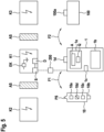
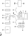
- Fig. 1 shows a device for automatically monitoring an electrotechnical work process according to a first embodiment of the present invention
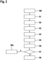
- Fig. 2 shows a flowchart of a method for automatically monitoring an electrical engineering workflow according to the first embodiment of the present invention.
- the device for automatically monitoring an electrotechnical work process is equipped with a mobile communication device 1, which has a first input device 1b, a first output device 1a, a first storage device 1c and a first bidirectional communication interface 1d.
- the mobile communication device 1 is, for example, a smartphone or laptop computer with a GSM connection and a wireless transmission function (e.g. WLAN function or Bluetooth function or mobile radio function or similar) for the first bidirectional communication interface 1d, wherein the first input device 1b can be a keyboard or a touchscreen and the first output device 1a can be a screen.
- a wireless transmission function e.g. WLAN function or Bluetooth function or mobile radio function or similar
- a work step sequence program for the electrotechnical work sequence is stored in the first storage device 1c and can be called up by a corresponding user input.
- the work step sequence program shows the user work step instructions A which are to be carried out and confirmed via a confirmation field Q.
- the device for automatically monitoring an electrotechnical work process is further equipped with a mobile voltage testing device 10, which has a second input device 10c, a second output device 10a, a second storage device 10d and a second bidirectional communication interface 10b, here for the wireless transmission function.
- the voltage testing device 10 has a test probe PS, which can be placed in contact or non-contact with a designated test point for voltage testing.
- At least one test parameter is stored in the second storage device 10d of the mobile voltage testing device and can be queried and/or set by the mobile communication device 1 via the first communication connection F1.
- This test parameter includes, for example, an acoustic or electronic display setting of the second output device 10a and/or an additional function and/or a nominal data parameter, in particular a voltage measuring range, and/or a battery capacity and/or a mandatory test time of the repeat test and/or an operational readiness of the mobile voltage testing device 10.
- the work step sequence program establishes a first bidirectional communication connection F1 between the mobile communication device 1 and the mobile voltage testing device 10 via the first bidirectional Communication interface 1d and the second bidirectional communication interface 10b can be set up.
- a second bidirectional communication connection F2 between the mobile communication device 1 and a central stationary communication device 100 with a third bidirectional communication interface 100a can be set up via the first bidirectional communication interface 1d and the third bidirectional communication interface 100a, here also as a wireless transmission function (e.g. WLAN function or as WLAN/Internet function).
- the central stationary communication device 100 is, for example, a local user server or a central provider server.
- the electrotechnical work sequence is to be carried out on a live electronic component K1, for example a distribution cabinet or during switching operations on electrical systems (e.g. low-voltage or high-voltage systems indoors or outdoors or overhead lines) which have a voltage switch S for isolating, i.e. for interrupting the voltage supply to the electronic component K1.
- a live electronic component K1 for example a distribution cabinet or during switching operations on electrical systems (e.g. low-voltage or high-voltage systems indoors or outdoors or overhead lines) which have a voltage switch S for isolating, i.e. for interrupting the voltage supply to the electronic component K1.
- step S0 initialization takes place on the mobile communication device 1 by a corresponding input by the user on the first input device 1b.
- the first bidirectional communication connection F1 is set up between the mobile communication device 1 and the mobile voltage testing device 10.
- an automatic connection can be set up with subsequent acknowledgement by the mobile communication device.
- the at least one test parameter can be queried and/or set by the mobile communication device 1 via the first communication connection F1.
- step S1 the work step sequence program is started on a mobile communication device 1 by means of a further input by the user at the first input device 1b of the mobile communication device 1.
- step S2 an output S2 of a work step instruction A for disconnecting the voltage-carrying electronic component K1 to make the electronic component K1 voltage-free, e.g. by changing the switch position of the voltage switch S or a corresponding software switch via the wireless connection function, takes place on the first output device 1a of the mobile communication device 1 by the work step sequence program.
- a manual confirmation S3 of the activation of the electronic component K1 on the mobile communication device takes place in step S3 via an input by the user in the confirmation field Q.
- a further work step instruction A for checking that the electronic component K1 is free of voltage by means of the mobile voltage testing device 10 on the first output device 1a of the mobile communication device 1 is output by the work step sequence program in step S4.
- the user then carries out the check for the absence of voltage of the electronic component K1 in step S5 using the mobile voltage testing device 10 by placing the test probe PS for voltage testing at the intended test point and triggering the voltage measurement, e.g. by pressing a corresponding button on the second input device 10c.
- the voltage testing device 10 is automatically put into the measuring state after being switched on, possibly after a self-test.
- step S6 the test result is communicated S6 from the mobile voltage testing device 10 to the mobile communication device 1 via the first bidirectional communication connection F1.
- step S7 the check result is checked by the operation sequence program of the mobile communication device 1.
- step S7 If the test result indicates that there is no voltage (Y in step S7), the check of the absence of voltage of the electronic component K1 is automatically confirmed in step S8 by issuing a confirmation signal by the mobile communication device, which may cause the output of a further work step instruction A or the termination of the work step sequence program.
- step S9a a first alarm signal is output by the mobile communication device 1 via the first output device 1a, e.g. in the form of an optical and/or acoustic signal and the possible output of a further work step instruction A is prevented.
- Fig. 3 shows a device for automatically monitoring an electrotechnical work process according to a second embodiment of the present invention
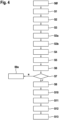
- Fig. 4 shows a flowchart of a method for automatically monitoring an electrical engineering workflow according to the second embodiment of the present invention.
- the device for automatically monitoring an electrotechnical work process according to Fig. 3 differs from the device according to Fig. 1 in that the electronic component K1 has a safety device for securing the electronic component K1 against being switched on again, which in the present example is a stationary or mobile lock D and is to be actuated by the user as part of the work process.
- a safety device for securing the electronic component K1 against being switched on again which in the present example is a stationary or mobile lock D and is to be actuated by the user as part of the work process.
- the user must install a clamping device EK for earthing and short-circuiting the electronic component K1 and a barrier device AS for securing and isolating the adjacent live electronic components K2, K3.
- steps S0 to S3 are carried out as described above in connection with the first embodiment.
- steps S3a and S3b are additionally carried out in the second embodiment.
- step S3a an operation step instruction A is output S3a to secure the electronic component K1 against being switched on again by the operation step sequence program, wherein in this case the lock D is to be used by the user.
- step S3b a manual confirmation S3b of securing the electronic component K1 against being switched on again on the mobile communication device 1 takes place via an input by the user in the confirmation field Q.
- steps S4 to S8 or S4 to S9a are carried out as already described above.
- step S10 an operation step instruction A for grounding and short-circuiting the electronic component K1 is output by the operation step sequence program, wherein in this case the user is to use the clamping device EK.
- step S11 After grounding and short-circuiting the electronic component K1, in step S11 the grounding and short-circuiting of the electronic component K1 is manually confirmed on the mobile communication device 1 via an input by the user on the confirmation field Q.
- a work step instruction A is issued S12 to secure and isolate the adjacent live electronic Components K2, K3 through the work step sequence program, in this case using the barrier device AS.
- step S13 After securing and blocking, the securing and blocking of adjacent live electronic components K2, K3 on the mobile communication device 1 is manually confirmed in step S13 via an input by the user in the confirmation field Q.
- Fig. 5 shows a device for automatically monitoring an electrotechnical work process according to a third embodiment of the present invention
- Fig. 6 shows a flowchart of a method for automatically monitoring an electrical engineering workflow according to the third embodiment of the present invention.
- the device for automatically monitoring an electrotechnical work process according to Fig. 5 differs from the device according to Fig. 1 in that the confirmation S3' of the activation of the electronic component K1 is carried out automatically by an activation confirmation device 200 that is communicatively connected to the mobile communication device 1 and not manually by the user.
- the automatic confirmation S3' can be triggered by a user input in the confirmation field Q after the work step instruction A for activation of a live electronic component K1 has been issued in step S2.
- the release confirmation device 200 is, for example, also equipped with a wireless transmission function and/or is wired or partially wired to the voltage switch S and the mobile communication device 1.
- step S30 the operation of the work step sequence program is checked. If the confirmation is successful (Y in step S30), the work step sequence program proceeds to step S4 and following, as already described above.
- step S30 If confirmation fails (N in step S30), a second alarm signal is output by the mobile communication device 1 in step S9b and the output of further work step instructions A is stopped.
- the release confirmation device 200 has, for example, an image recognition device and/or a switching state reporting device of the voltage switch S to be actuated for release and/or an electroluminescence measuring device for measuring an electric field at the electronic component K1.
- Fig. 7 shows a device for automatically monitoring an electrotechnical work process according to a fourth embodiment of the present invention
- Fig. 8 shows a flowchart of a method for automatically monitoring an electrical engineering workflow according to the fourth embodiment of the present invention.
- the device for automatically monitoring an electrotechnical work process according to Fig. 7 differs from the device according to Fig. 3 in that the confirmation S3b' of securing the electronic component K1 against being switched on again is carried out automatically by a restart protection confirmation device 300 that is communicatively connected to the mobile communication device 1 and not manually by the user.
- the automatic confirmation S3b' can be triggered by a user input in the confirmation field Q after the work step instruction A for securing the electronic component K1 against being switched on again has been issued.
- the reclosure protection confirmation device 300 is, for example, also equipped with a wireless transmission function and/or wired or partially wired to the lock D and the mobile communication device 1.
- step S30a the confirmation of the work step sequence program is checked. If the confirmation is successful (Y in step S30a), the work step sequence program proceeds to step S4 and following, as already described above.
- step S30a If confirmation fails (N in step S30a), a third alarm signal is output by the mobile communication device 1 in step S9c, and the output of further work step instructions A is stopped.
- the reclosure protection confirmation device 300 has, for example, an image recognition device and/or a locking state reporting device of the lock D to be actuated for reclosure protection.
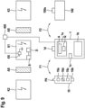
- Fig. 9 shows a device for automatically monitoring an electrotechnical work process according to a fifth embodiment of the present invention
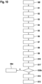
- Fig. 10 shows a flowchart of a method for automatically monitoring an electrical engineering workflow according to the fifth embodiment of the present invention.
- the device for automatically monitoring an electrotechnical work process according to Fig. 9 differs from the device according to Fig. 3 in that the confirmation S11 ⁇ of the earthing and short-circuiting of the electronic component K1 is carried out automatically by an earthing/short-circuit confirmation device 400 that is communicatively connected to the mobile communication device 1 and not manually by the user.
- the automatic confirmation S11 ⁇ can be triggered by a user input in the confirmation field Q after the work step instruction A for earthing and short-circuiting the electronic component K1 has been issued.
- the grounding/short-circuit confirmation device 400 is, for example, also equipped with a wireless transmission function and/or is wired or partially wired to the terminal device EK and the mobile communication device 1.
- step S30b the confirmation of the work step sequence program is checked. If the confirmation is successful (Y in step S30b), the work step sequence program proceeds to step S12 and following, as already described above.
- step S30b If confirmation fails (N in step S30b), a fourth alarm signal is output by the mobile communication device 1 in step 9d and the output of further work step instructions A is stopped.
- the grounding/short-circuit confirmation device 400 has, for example, an image recognition device and/or a clamp detection device (e.g. pressure switch, limit switch or similar) for detecting a clamping of the clamping device EK used for grounding and short-circuiting and/or a device for detecting ball fixed points of a ball head cover of the clamping device EK.
- a clamp detection device e.g. pressure switch, limit switch or similar
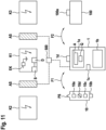
- Fig. 11 shows a device for automatically monitoring an electrotechnical work process according to a sixth embodiment of the present invention
- Fig. 12 shows a flowchart of a method for automatically monitoring an electrical engineering workflow according to the sixth embodiment of the present invention.
- the device for automatically monitoring an electrotechnical work process according to Fig. 11 differs from the device according to Fig. 3 in that the confirmation S13 ⁇ of securing and blocking off the adjacent live electronic components K2, K3 is carried out automatically by a securing/blocking confirmation device 500 that is communicatively connected to the mobile communication device 1 and not manually by the user.
- the automatic confirmation S13 ⁇ can be triggered by a user input in the confirmation field Q after the work step instruction A for securing and blocking off the electronic component K1 has been issued.
- the security/barrier confirmation device 500 is, for example, also equipped with a wireless transmission function and/or wired or partially wired to the barrier device AS and the mobile communication device 1.
- step S30c the confirmation of the work step sequence program is checked. If the confirmation is successful (Y in step S30c), the Work step sequence program advances to any further work step instructions or is terminated.
- step 30c If confirmation fails (N in step 30c), a fifth alarm signal is output by the mobile communication device 1 in step S9e and the output of further work step instructions A is stopped.
- the securing/barrier confirmation device 500 has, for example, an image recognition device and/or a position detection device of a position of the barrier device AS used for securing and barring.
- Fig. 13 shows a device for automatically monitoring an electrical engineering workflow according to a seventh embodiment of the present invention.
- the device for automatically monitoring an electrotechnical work process according to Fig. 13 differs from the device according to Fig. 3 in that an item of protective equipment SA is intended for a user which has a third bidirectional communication interface VS.
- a third bidirectional communication connection F3 can be set up between the mobile communication device 1 and the protective equipment item SA via the first bidirectional communication interface 1d and the third bidirectional communication interface VS in the work step sequence program.
- the mobile communication device 1 transmits at least one of the first to fifth alarm signals via the third bidirectional communication connection F3 to the protective equipment item SA in order to trigger an optical and/or acoustic warning device AE and/or a vibration alarm device attached to the protective equipment item SA.
- the protective equipment item SA is, for example, a protective jacket, a protective helmet, safety goggles, a protective coat, protective overalls, a switching coat or similar.
- the protective equipment item SA also has a vital sensor VS, and the user’s vital data are available via the third bidirectional Communication connection F3 can be transmitted to the mobile communication device 1.
- the mobile communication device 1 is set up to establish a fourth bidirectional communication connection F4 with a rescue center RZ when critical vital data of the user are transmitted, e.g. via the GSM function.
- the protective equipment item SA can also have additional sensors (not shown) to increase safety, e.g. a humidity sensor, a motion sensor, an acceleration sensor, etc., which can block or cancel a work step instruction via a wireless communication connection.
- additional sensors e.g. a humidity sensor, a motion sensor, an acceleration sensor, etc., which can block or cancel a work step instruction via a wireless communication connection.
- Fig. 14 shows a voltage testing device for a device for automatically monitoring an electrotechnical work process according to an eighth embodiment of the present invention
- Fig. 15 shows a flowchart of a method for automatically monitoring an electrical engineering workflow according to the eighth embodiment of the present invention.
- the mobile voltage testing device 10' is communicatively connected to the mobile communication device 1. It has a voltage test point confirmation device 10e for confirming the correct voltage test point, for example an image recognition device and/or a sensor device integrated in the mobile voltage test device.
- a voltage test point confirmation device 10e for confirming the correct voltage test point, for example an image recognition device and/or a sensor device integrated in the mobile voltage test device.
- step S5a After steps S0 to S5, which were previously described, i.e. before communicating the test result in step S6, the voltage test point is additionally checked in step S5a by the voltage test point confirmation device 10e to ensure that the voltage was measured at the intended voltage test point or that the voltage test device 10' was operated properly.
- step S5a If the test is successful (Y in step S5a), the test result is communicated from the mobile voltage testing device 10' to the mobile communication device 1 in step S6. Otherwise, the work step sequence program jumps back to step S4.
Landscapes
- Physics & Mathematics (AREA)
- General Physics & Mathematics (AREA)
- Engineering & Computer Science (AREA)
- Environmental & Geological Engineering (AREA)
- Automation & Control Theory (AREA)
- Quality & Reliability (AREA)
- Atmospheric Sciences (AREA)
- Biodiversity & Conservation Biology (AREA)
- Ecology (AREA)
- Environmental Sciences (AREA)
- Life Sciences & Earth Sciences (AREA)
- Telephone Function (AREA)
- General Factory Administration (AREA)
- Selective Calling Equipment (AREA)
Claims (33)
- Procédé de surveillance automatique d'un flux de travaux électrotechnique ayant une pluralité d'opérations, qui comporte les étapes suivantes de :établir (S0) une première liaison de communication bidirectionnelle (F1) entre un appareil de communication mobile (1) et un détecteur de présence de tension mobile (10 ; 10') ;lancer (S1) un programme de séquence d'opérations sur un appareil de communication mobile (1) au moyen d'un dispositif d'entrée (1b) de l'appareil de communication mobile (1),générer (S2) une instruction d'opération (A) pour séparer un composant électronique sous tension (K1) pour entraîner une absence de tension du composant électronique (K1) sur un dispositif de sortie (1a) de l'appareil de communication mobile (1) par le programme de séquence d'opérations ;confirmer automatiquement ou manuellement (S3 ; S3') la séparation du composant électronique (K1) sur l'appareil de communication mobile (1) ;après la confirmation (S3 ; S3') de la séparation du composant électronique (K1), générer (S4) une instruction d'opération (A) pour vérifier l'absence de tension du composant électronique (K1) au moyen du détecteur de présence de tension mobile (10 ; 10') sur le dispositif de sortie (1a) de l'appareil de communication mobile (1) par le programme de séquence d'opérations ;vérifier (S5) l'absence de tension du composant électronique (K1) au moyen du détecteur de présence de tension mobile (10 ; 10') ;communiquer (S6) le résultat de vérification du détecteur de présence de tension mobile (10 ; 10') à l'appareil de communication mobile (1) ;si le résultat de vérification indique une absence de tension, confirmer automatiquement (S8) la vérification de l'absence de tension du composant électronique (K1) en émettant un signal de confirmation par l'appareil de communication mobile (1) ;si le résultat de vérification n'indique aucune absence de tension, générer (S9a) un premier signal d'alarme par l'appareil de communication mobile (1).
- Procédé selon la revendication 1, dans lequel une deuxième liaison de communication bidirectionnelle (F2) est établie entre l'appareil de communication mobile (1) et un appareil de communication fixe central (100), et dans lequel le résultat de vérification du détecteur de présence de tension mobile (10 ; 10') est communiqué à l'appareil de communication fixe central (100).
- Procédé selon la revendication 1 ou 2, dans lequel au moins un paramètre de vérification pouvant être enregistré dans le détecteur de présence de tension mobile (10 ; 10') peut être consulté et/ou réglé par l'appareil de communication mobile (1).
- Procédé selon la revendication 3, dans lequel le paramètre de vérification comprend un réglage d'indication acoustique ou électronique et/ou une fonction supplémentaire et/ou un paramètre de données de consigne, en particulier une plage de mesure de tension, et/ou une capacité de batterie et/ou un temps de vérification obligatoire pour une vérification répétée et/ou une disponibilité opérationnelle du détecteur de présence de tension mobile (10 ; 10').
- Procédé selon l'une des revendications précédentes, dans lequel l'appareil de communication mobile (1) comporte un dispositif d'enregistrement temporel et la vérification (S5) de l'absence de tension du composant électronique (K1) en utilisant le détecteur de présence de tension mobile (10 ; 10') est enregistrée sur la base du temps par le programme de séquence d'opérations et stocké dans l'appareil de communication mobile (1).
- Procédé selon l'une des revendications précédentes, dans lequel l'appareil de communication mobile (1) comporte un dispositif de localisation GPS et la vérification (S5) de l'absence de tension du composant électronique (K1) en utilisant le détecteur de présence de tension (10 ; 10') est enregistrée sur la base de l'emplacement par le programme de séquence d'opérations et stocké dans l'appareil de communication mobile (1).
- Procédé selon l'une des revendications précédentes, dans lequel l'appareil de communication mobile (1) comporte un dispositif de prévision météorologique et génère, dans le cas d'une prévision météorologique prédéterminée, en particulier d'une prévision d'orage, une indication d'avertissement dans le programme de séquence d'opérations.
- Procédé selon l'une des revendications précédentes, dans lequel la confirmation (S3') de la séparation du composant électronique (K1) est exécutée automatiquement par un dispositif de confirmation de séparation (200) relié de manière communicante à l'appareil de communication mobile (1) et, en cas d'échec de confirmation (S3'), une sortie (S9B) d'un deuxième signal d'alarme est générée par l'appareil de communication mobile (1), et dans lequel le dispositif de confirmation de séparation (200) comporte un dispositif de reconnaissance d'image et/un dispositif d'indication d'état de commutation d'un commutateur de tension matériel et/ou logiciel (S) qui est actionné pour la séparation et/ou un dispositif de mesure d'électroluminescence pour mesurer un champ électrique sur le composant électronique (K1).
- Procédé selon l'une des revendications précédentes, dans lequel, après la confirmation (S3 ; S3') de la séparation du composant électronique (K1) et avant de générer (S4) l'instruction d'opération (A) pour vérifier l'absence de tension du composant électronique (K1), une sortie (S3a) d'une instruction d'opération (A) est générée par le programme de séquence d'opérations afin de protéger le composant électronique (K1) contre tout réenclenchement, et une confirmation automatique ou manuelle (S3b ; S3b') de la protection du composant électronique (K1) contre tout réenclenchement est ensuite générée sur l'appareil de communication mobile (1).
- Procédé selon la revendication 9, dans lequel la confirmation (S3b') de la protection du composant électronique (K1) contre tout réenclenchement est effectuée automatiquement par un dispositif de confirmation de protection contre tout réenclenchement (300) relié de manière communicante à l'appareil de communication mobile (300) et en cas d'échec de confirmation (S3b'), une sortie (S9c) d'un troisième signal d'alarme est générée par l'appareil de communication mobile (1), et dans lequel le dispositif de confirmation de protection contre tout réenclenchement (300) comporte un dispositif de reconnaissance d'image et/ou un dispositif d'indication d'état de blocage d'un verrou (D) qui doit être actionné pour protéger contre tout réenclenchement.
- Procédé selon l'une des revendications précédentes, dans lequel, si le résultat de vérification indique une absence de tension et si le signal de confirmation est généré par l'appareil de communication mobile (1), une sortie (S10) d'une instruction d'opération (A) pour la mise à la terre et la mise en court-circuit du composant électronique (K1) est générée par le programme de séquence d'opérations, puis une confirmation automatique ou manuelle (S11 ; S11') de la mise à la terre et de la mise en court-circuit du composant électronique (K1) sur l'appareil de communication mobile (1) .
- Procédé selon la revendication 10, dans lequel la confirmation (S11') de la mise à la terre et de la mise en court-circuit du composant électronique (K1) est générée automatiquement par un dispositif de confirmation de mise à la terre/en court-circuit (400) relié de manière communicante à l'appareil de communication mobile (1) et en cas d'échec de confirmation (S11'), une sortie (S9d) d'un quatrième signal d'alarme est générée par l'appareil de communication mobile (1) et dans lequel le dispositif de confirmation de mise à la terre/en court-circuit (400) comporte un dispositif de reconnaissance d'image et/ou un dispositif de détection de serrage pour détecter un serrage d'un dispositif de serrage (EK) utilisé pour la mise à la terre et la mise en court-circuit et/ou un dispositif pour détecter des points sphériques fixes d'une tête sphérique du dispositif de serrage (EK).
- Procédé selon la revendication 11 ou 12, dans lequel après la confirmation (S11) de la mise à la terre et de la mise en court-circuit du composant électronique (K1), une sortie (S12) d'une instruction d'opération (A) est générée par le programme de séquence d'opérations pour protéger et séparer par barrière des composants électroniques sous tension adjacents (K2, K3), et une confirmation automatique ou manuelle (S13 ; S13') de la protection et de la séparation par barrière de composants électroniques sous tension adjacents (K2, K3) est ensuite générée sur l'appareil de communication mobile (1).
- Procédé selon la revendication 13, dans lequel la confirmation (S13') de la protection et de la séparation par barrière de composants électroniques sous tension adjacents (K2, K3) est effectuée automatiquement par un dispositif de confirmation de protection/séparation par barrière (500) relié de manière communicante à l'appareil de communication mobile (1) et en cas d'échec de confirmation (S13'), une sortie (S9e) d'un cinquième signal d'alarme est générée par l'appareil de communication mobile (1) et dans lequel le dispositif de confirmation de protection/séparation par barrière (500) comporte un dispositif de reconnaissance d'image et/ou un dispositif de détection de position (LE) d'une position d'un dispositif de barrière (AS) utilisé pour la protection et la séparation par barrière.
- Procédé selon l'une des revendications précédentes, dans lequel un équipement de protection (SA) est prévu pour un utilisateur, dans lequel une troisième liaison de communication bidirectionnelle (F3) est établie entre l'appareil de communication mobile (1) et l'équipement de protection (SA), et dans lequel l'appareil de communication mobile (1) transmet au moins un des premier à cinquième signaux d'alarme via la troisième liaison de communication bidirectionnelle (F3) à l'équipement de protection (SA) afin de déclencher un dispositif d'avertissement (AE) optique et/ou acoustique et/ou un dispositif d'alarme par vibration fixé sur l'équipement de protection (SA).
- Procédé selon la revendication 15, dans lequel l'équipement de protection (SA) comporte une veste de protection et/ou un casque de protection et/ou des lunettes de protection et/ou un manteau de sécurité et/ou une combinaison de protection et/ou un manteau de protection.
- Procédé selon la revendication 15 ou 16, dans lequel l'équipement de protection (SA) comporte un capteur de sens vitaux (VS) et les données vitales de l'utilisateur sont transmises à l'appareil de communication mobile (1) via la troisième liaison de communication bidirectionnelle (F3) .
- Procédé selon la revendication 15, dans lequel l'appareil de communication mobile (1) est conçu pour établir, en cas de transmission de données vitales critiques de l'utilisateur, une quatrième liaison de communication unidirectionnelle ou bidirectionnelle (F4) avec un centre de secours (RZ).
- Procédé selon l'une des revendications précédentes, dans lequel au moins une partie des instructions de travail, la confirmation respective associée ou l'échec de confirmation et le signal d'alarme respectif en cas d'échec de confirmation, sont enregistrés et stockés dans l'appareil de communication mobile (1).
- Procédé selon l'une des revendications précédentes, dans lequel l'appareil de communication mobile (1) comprend un téléphone intelligent ou un ordinateur portable ou une tablette ou des lunettes intelligentes ou une montre intelligente.
- Procédé selon l'une des revendications précédentes, dans lequel un dispositif de confirmation de point de détection de tension (10e) relié de manière communicante à l'appareil de communication mobile (1) est prévu pour confirmer le point de détection de tension, dans lequel avant la communication (S6) du résultat de vérification, un contrôle (S5a) du point de détection de tension est effectué par le dispositif de confirmation de point de détection de tension (10e) et dans lequel la communication (S6) du résultat de vérification du détecteur de présence de tension mobile (10 ; 10') à l'appareil de communication mobile (10) est uniquement réalisée en cas de contrôle réussi.
- Procédé selon la revendication 21, dans lequel le dispositif de confirmation de point de détection de tension (10e) comporte un dispositif de reconnaissance d'image et/ou un dispositif de capteur intégré dans le détecteur de présence de tension mobile (10 ; 10').
- Dispositif de surveillance automatique d'un flux de travaux électrotechnique, conçu pour la mise en œuvre du procédé selon l'une des revendications précédentes, comportant :un appareil de communication mobile (1) qui comporte un premier dispositif d'entrée (1b), un premier dispositif de sortie (1a), un premier dispositif de stockage (1c) et une première interface de communication bidirectionnelle (1d) ; un programme de séquence d'opérations stocké sur l'appareil de communication mobile (1) ;un détecteur de présence de tension mobile (10 ; 10') qui comporte un second dispositif d'entrée (10c), un second dispositif de sortie (10a), un second dispositif de stockage (10d) et une deuxième interface de communication bidirectionnelle (10b) ;dans lequel une première liaison de communication bidirectionnelle (F1) peut être établie entre l'appareil de communication mobile (1) et le détecteur de présence de tension mobile (10 ; 10') via les première et deuxième interfaces de communication bidirectionnelle (1d, 10b).
- Dispositif selon la revendication 23, en particulier pour la mise en œuvre du procédé selon la revendication 8, comportant en outre un dispositif de confirmation de séparation (200) pouvant être relié de manière communicante à l'appareil de communication mobile (1), lequel dispositif de confirmation comporte un dispositif de reconnaissance d'image et/ou un dispositif d'indication de commutation (SM) d'un commutateur de tension (S) qui doit être actionné pour 1 la séparation et/ou un dispositif de mesure d'électroluminescence pour mesurer un champ électrique sur le composant électronique (K1).
- Dispositif selon la revendication 23 ou 24, en particulier pour la mise en œuvre du procédé selon la revendication 10, comportant en outre un dispositif de confirmation de protection contre tout réenclenchement (300) pouvant être relié à l'appareil de communication mobile (1), lequel dispositif de confirmation comporte un dispositif de reconnaissance d'image et/ou un dispositif d'indication d'état de blocage d'un verrou (D) qui doit être actionné pour la protection contre tout réenclenchement.
- Dispositif selon la revendication 23, 24 ou 25, en particulier pour la mise en œuvre du procédé selon la revendication 12, comportant en outre un dispositif de confirmation de mise à la terre/en court-circuit (400) pouvant être relié à l'appareil de communication mobile (1), lequel dispositif de confirmation comporte un dispositif de reconnaissance d'image et/ou un dispositif de détection de serrage pour détecter un serrage d'un dispositif de serrage (EK) utilisé pour la mise à la terre et la mise en court-circuit et/ou un dispositif de détection de points sphériques fixes d'une tête sphérique du dispositif de serrage (EK).
- Dispositif selon l'une des revendications 23 à 26, en particulier pour la mise en œuvre du procédé selon la revendication 14, comportant en outre un dispositif de confirmation de protection/séparation par barrière (500) pouvant être relié à l'appareil de communication mobile (1), lequel dispositif de confirmation comporte un dispositif de reconnaissance d'image et/ou un dispositif de détection de position (LE) d'une position d'un dispositif de barrière (AS) utilisé pour la protection et la séparation par barrière.
- Dispositif selon l'une des revendications 23 à 27 pour la mise en œuvre du procédé selon la revendication 15, comportant en outre un équipement de protection (SA) pour un utilisateur avec une troisième interface de communication bidirectionnelle (SK) et un dispositif d'avertissement optique et/ou acoustique (AE) et/ou un dispositif d'alarme par vibration monté sur l'équipement de protection (SA), dans lequel une troisième liaison de communication bidirectionnelle (F3) peut être établie entre l'appareil de communication mobile (1) et l'équipement de protection (SA) via les première et troisième interfaces de communication bidirectionnelle (SK).
- Dispositif selon la revendication 28, dans lequel l'équipement de protection (SA) comporte une veste de protection et/ou un casque de protection et/ou des lunettes de protection et/ou un manteau de sécurité et/ou une combinaison de protection et/ou un manteau de protection.
- Dispositif selon la revendication 28 ou 29, dans lequel l'équipement de protection (SA) comporte un capteur de sens vitaux (VS).
- Dispositif selon l'une des revendications 23 à 30, dans lequel l'appareil de communication mobile (1) comprend un téléphone intelligent ou un ordinateur portable ou une tablette ou des lunettes intelligentes ou une montre intelligente.
- Dispositif selon l'une des revendications 23 à 31, comprenant en outre un dispositif de confirmation de point de détection de tension (10e) pouvant être relié à l'appareil de communication mobile (1) pour confirmer le point de détection de tension du détecteur de présence de tension mobile (10 ; 10') qui comporte un dispositif de reconnaissance d'image et/ou un dispositif de capteur intégré dans le détecteur de présence de tension mobile (10 ; 10').
- Dispositif selon l'une des revendications 28 à 31, dans lequel l'équipement de protection (SA) comporte un dispositif de capteur qui est configuré pour surveiller l'état, l'utilisation ou l'entretien de l'équipement de protection (SA) et pour le transmettre à l'appareil de communication fixe central (100) via la troisième liaison de communication bidirectionnelle (SK).
Applications Claiming Priority (2)
| Application Number | Priority Date | Filing Date | Title |
|---|---|---|---|
| DE102020210371.2A DE102020210371B3 (de) | 2020-08-14 | 2020-08-14 | Verfahren zum automatischen Überwachen eines elektrotechnischen Arbeitsablaufs und entsprechende Vorrichtung |
| PCT/EP2021/072642 WO2022034230A1 (fr) | 2020-08-14 | 2021-08-13 | Procédé de surveillance automatique d'un flux opérationnel électrotechnique et dispositif correspondant |
Publications (3)
| Publication Number | Publication Date |
|---|---|
| EP4176272A1 EP4176272A1 (fr) | 2023-05-10 |
| EP4176272C0 EP4176272C0 (fr) | 2024-11-13 |
| EP4176272B1 true EP4176272B1 (fr) | 2024-11-13 |
Family
ID=77595531
Family Applications (1)
| Application Number | Title | Priority Date | Filing Date |
|---|---|---|---|
| EP21763304.9A Active EP4176272B1 (fr) | 2020-08-14 | 2021-08-13 | Procédé de surveillance automatique d'un flux opérationnel électrotechnique et dispositif correspondant |
Country Status (5)
| Country | Link |
|---|---|
| US (1) | US12567285B2 (fr) |
| EP (1) | EP4176272B1 (fr) |
| DE (1) | DE102020210371B3 (fr) |
| WO (1) | WO2022034230A1 (fr) |
| ZA (1) | ZA202301269B (fr) |
Family Cites Families (11)
| Publication number | Priority date | Publication date | Assignee | Title |
|---|---|---|---|---|
| DE9400903U1 (de) * | 1994-01-20 | 1994-03-31 | Nied, Rolf, 97959 Assamstadt | Spannungsprüfungseinrichtung |
| DE102011104819A1 (de) * | 2011-06-18 | 2012-12-20 | Daimler Ag | Kraftfahrzeughochvoltsystem |
| EP3052950B1 (fr) | 2013-10-01 | 2024-12-11 | HD Electric Company | Système de contrôle de détecteur haute tension |
| DE102014218096A1 (de) | 2014-09-10 | 2016-03-10 | Fraunhofer-Gesellschaft zur Förderung der angewandten Forschung e.V. | Verfahren und Vorrichtung zur Überwachung eines Fertigungs- und/oder Montageprozesses |
| DE102014218481A1 (de) * | 2014-09-15 | 2016-03-17 | Kries Energietechnik Gmbh & Co. Kg | Spannungsprüfsystem |
| JP6604076B2 (ja) * | 2015-07-29 | 2019-11-13 | 東京電力ホールディングス株式会社 | 監視制御システム |
| DE102016104692A1 (de) | 2016-03-15 | 2017-09-21 | ioxp GmbH | System zur Protokollierung der Durchführung von Arbeitsprozessen |
| CN108656954B (zh) * | 2018-07-13 | 2020-04-14 | 中车唐山机车车辆有限公司 | 高压箱、高压系统及电力动车组 |
| FR3092230B1 (fr) * | 2019-02-06 | 2021-02-12 | Neoratech | Dispositif de vérification d’absence de tension d’un circuit électrique |
| AT521697B1 (de) * | 2019-02-08 | 2020-04-15 | Adaptive Regelsysteme Ges M B H | Mobiler Elektroverteiler mit Notsignaleingang |
| US11650580B2 (en) * | 2020-11-19 | 2023-05-16 | Caterpillar Inc. | Monitoring system for engine performance and failure prediction |
-
2020
- 2020-08-14 DE DE102020210371.2A patent/DE102020210371B3/de active Active
-
2021
- 2021-08-13 WO PCT/EP2021/072642 patent/WO2022034230A1/fr not_active Ceased
- 2021-08-13 EP EP21763304.9A patent/EP4176272B1/fr active Active
- 2021-08-13 US US18/018,329 patent/US12567285B2/en active Active
-
2023
- 2023-01-31 ZA ZA2023/01269A patent/ZA202301269B/en unknown
Also Published As
| Publication number | Publication date |
|---|---|
| WO2022034230A1 (fr) | 2022-02-17 |
| US12567285B2 (en) | 2026-03-03 |
| EP4176272C0 (fr) | 2024-11-13 |
| EP4176272A1 (fr) | 2023-05-10 |
| ZA202301269B (en) | 2024-05-30 |
| DE102020210371B3 (de) | 2022-02-17 |
| US20230298390A1 (en) | 2023-09-21 |
Similar Documents
| Publication | Publication Date | Title |
|---|---|---|
| EP3192139B1 (fr) | Procédé et dispositif de détection d'un courant de court-circuit continu | |
| EP3442822B1 (fr) | Station de recharge et procede correspondant | |
| DE102019112839B3 (de) | Schutz- und Überwachungseinrichtung in einer Ladeinfrastruktur zum Laden von elektrisch angetriebenen Fahrzeugen und Verfahren zur Überwachung einer Ladeinfrastruktur | |
| DE69906906T2 (de) | Selbstgespeistes isoliertes verriegelungssystem zur bereichsauswahl für schutzschalter mit elektronischer auslöseschaltung | |
| EP3273459A1 (fr) | Dispositif et procede de surveillance d'une unite d'interruption dans un reseau d'alimentation en energie electrique et station de distribution comprenant une unite d'interruption surveillee | |
| DE102016011803B4 (de) | Testvorrichtung und Verfahren zur Überprüfung eines in einem Gerät angeordneten Vibrationsmotors | |
| EP3435512A1 (fr) | Station de charge à surveillance de courant différentiel destinée à charger un accumulateur d'énergie électrique d'un véhicule électrique | |
| DE102010056006B4 (de) | Verfahren zur Überwachung eines Leitungsnetzes für ein Fahrzeug sowie entsprechende Überwachungsvorrichtung und Fahrzeug | |
| EP2008352A1 (fr) | Procédé de contrôle de la qualité de l'énergie électrique dans un réseau d'alimentation en énergie électrique, appareil de terrain de contrôle de la qualité de courant et système de contrôle de la qualité de courant | |
| DE102016222271B4 (de) | Schaltungsanordnung zur Ansteuerung einer Ladedose eines Elektro- oder Hybridfahrzeugs und Ladestecker | |
| EP4176272B1 (fr) | Procédé de surveillance automatique d'un flux opérationnel électrotechnique et dispositif correspondant | |
| AT528086A2 (de) | Überwachungssystem zur berührungslosen Ferndiagnose und -kontrolle von automatischen Feuerlöschvorrichtungen zum lokalen Schutz elektrischer Vorrichtungen | |
| EP1058991B1 (fr) | Appareil radio a telecommande | |
| EP2571000B1 (fr) | Procédé et dispositif de détection d'actions mécaniques sur des installations électriques | |
| EP2899822B1 (fr) | Système de protection électrique pour une installation électrique et procédé correspondant | |
| EP3559684A1 (fr) | Dispositif et procédé permettant de protéger une personne contre un signal électrique | |
| EP3507874B1 (fr) | Procédé pour faire fonctionner un appareil de commutation électrique à l'intérieur d'une installation de commutation électrique | |
| EP3349197B1 (fr) | Module d'extraction d'énergie | |
| DE102016105602A1 (de) | Leistungsschalter sowie Verfahren zum Betrieb eines solchen Leistungsschalters | |
| EP3849034B1 (fr) | Agencement de sécurité pour au moins une station de transformation | |
| DE102024119549A1 (de) | Verfahren und Vorrichtung zum sicheren Betrieb eines NACS-Steckadapters | |
| EP2658068B1 (fr) | Dispositif de détection de surtension | |
| DE102011052712A1 (de) | Sicherheitseinrichtung für ein Kraftfahrzeug | |
| EP3669339A1 (fr) | Dispositif et procédé de commande à distance d'une installation de traitement sécurisé | |
| EP4718631A1 (fr) | Module d'outil, unité de montage et système de montage pour la mise à la terre et le court-circuit d'une ligne et procédé de couplage mécanique d'un module d'outil avec une pince |
Legal Events
| Date | Code | Title | Description |
|---|---|---|---|
| STAA | Information on the status of an ep patent application or granted ep patent |
Free format text: STATUS: UNKNOWN |
|
| STAA | Information on the status of an ep patent application or granted ep patent |
Free format text: STATUS: THE INTERNATIONAL PUBLICATION HAS BEEN MADE |
|
| PUAI | Public reference made under article 153(3) epc to a published international application that has entered the european phase |
Free format text: ORIGINAL CODE: 0009012 |
|
| STAA | Information on the status of an ep patent application or granted ep patent |
Free format text: STATUS: REQUEST FOR EXAMINATION WAS MADE |
|
| 17P | Request for examination filed |
Effective date: 20230131 |
|
| AK | Designated contracting states |
Kind code of ref document: A1 Designated state(s): AL AT BE BG CH CY CZ DE DK EE ES FI FR GB GR HR HU IE IS IT LI LT LU LV MC MK MT NL NO PL PT RO RS SE SI SK SM TR |
|
| DAV | Request for validation of the european patent (deleted) | ||
| DAX | Request for extension of the european patent (deleted) | ||
| GRAP | Despatch of communication of intention to grant a patent |
Free format text: ORIGINAL CODE: EPIDOSNIGR1 |
|
| STAA | Information on the status of an ep patent application or granted ep patent |
Free format text: STATUS: GRANT OF PATENT IS INTENDED |
|
| GRAS | Grant fee paid |
Free format text: ORIGINAL CODE: EPIDOSNIGR3 |
|
| INTG | Intention to grant announced |
Effective date: 20240904 |
|
| GRAA | (expected) grant |
Free format text: ORIGINAL CODE: 0009210 |
|
| STAA | Information on the status of an ep patent application or granted ep patent |
Free format text: STATUS: THE PATENT HAS BEEN GRANTED |
|
| AK | Designated contracting states |
Kind code of ref document: B1 Designated state(s): AL AT BE BG CH CY CZ DE DK EE ES FI FR GB GR HR HU IE IS IT LI LT LU LV MC MK MT NL NO PL PT RO RS SE SI SK SM TR |
|
| REG | Reference to a national code |
Ref country code: GB Ref legal event code: FG4D Free format text: NOT ENGLISH |
|
| REG | Reference to a national code |
Ref country code: CH Ref legal event code: EP |
|
| REG | Reference to a national code |
Ref country code: DE Ref legal event code: R096 Ref document number: 502021005811 Country of ref document: DE |
|
| REG | Reference to a national code |
Ref country code: IE Ref legal event code: FG4D Free format text: LANGUAGE OF EP DOCUMENT: GERMAN |
|
| U01 | Request for unitary effect filed |
Effective date: 20241213 |
|
| U07 | Unitary effect registered |
Designated state(s): AT BE BG DE DK EE FI FR IT LT LU LV MT NL PT RO SE SI Effective date: 20241223 |
|
| PG25 | Lapsed in a contracting state [announced via postgrant information from national office to epo] |
Ref country code: IS Free format text: LAPSE BECAUSE OF FAILURE TO SUBMIT A TRANSLATION OF THE DESCRIPTION OR TO PAY THE FEE WITHIN THE PRESCRIBED TIME-LIMIT Effective date: 20250313 Ref country code: HR Free format text: LAPSE BECAUSE OF FAILURE TO SUBMIT A TRANSLATION OF THE DESCRIPTION OR TO PAY THE FEE WITHIN THE PRESCRIBED TIME-LIMIT Effective date: 20241113 |
|
| PG25 | Lapsed in a contracting state [announced via postgrant information from national office to epo] |
Ref country code: ES Free format text: LAPSE BECAUSE OF FAILURE TO SUBMIT A TRANSLATION OF THE DESCRIPTION OR TO PAY THE FEE WITHIN THE PRESCRIBED TIME-LIMIT Effective date: 20241113 |
|
| PG25 | Lapsed in a contracting state [announced via postgrant information from national office to epo] |
Ref country code: NO Free format text: LAPSE BECAUSE OF FAILURE TO SUBMIT A TRANSLATION OF THE DESCRIPTION OR TO PAY THE FEE WITHIN THE PRESCRIBED TIME-LIMIT Effective date: 20250213 |
|
| PG25 | Lapsed in a contracting state [announced via postgrant information from national office to epo] |
Ref country code: GR Free format text: LAPSE BECAUSE OF FAILURE TO SUBMIT A TRANSLATION OF THE DESCRIPTION OR TO PAY THE FEE WITHIN THE PRESCRIBED TIME-LIMIT Effective date: 20250214 |
|
| PG25 | Lapsed in a contracting state [announced via postgrant information from national office to epo] |
Ref country code: PL Free format text: LAPSE BECAUSE OF FAILURE TO SUBMIT A TRANSLATION OF THE DESCRIPTION OR TO PAY THE FEE WITHIN THE PRESCRIBED TIME-LIMIT Effective date: 20241113 |
|
| PG25 | Lapsed in a contracting state [announced via postgrant information from national office to epo] |
Ref country code: RS Free format text: LAPSE BECAUSE OF FAILURE TO SUBMIT A TRANSLATION OF THE DESCRIPTION OR TO PAY THE FEE WITHIN THE PRESCRIBED TIME-LIMIT Effective date: 20250213 |
|
| PG25 | Lapsed in a contracting state [announced via postgrant information from national office to epo] |
Ref country code: SM Free format text: LAPSE BECAUSE OF FAILURE TO SUBMIT A TRANSLATION OF THE DESCRIPTION OR TO PAY THE FEE WITHIN THE PRESCRIBED TIME-LIMIT Effective date: 20241113 |
|
| PG25 | Lapsed in a contracting state [announced via postgrant information from national office to epo] |
Ref country code: SK Free format text: LAPSE BECAUSE OF FAILURE TO SUBMIT A TRANSLATION OF THE DESCRIPTION OR TO PAY THE FEE WITHIN THE PRESCRIBED TIME-LIMIT Effective date: 20241113 |
|
| PG25 | Lapsed in a contracting state [announced via postgrant information from national office to epo] |
Ref country code: CZ Free format text: LAPSE BECAUSE OF FAILURE TO SUBMIT A TRANSLATION OF THE DESCRIPTION OR TO PAY THE FEE WITHIN THE PRESCRIBED TIME-LIMIT Effective date: 20241113 |
|
| PLBE | No opposition filed within time limit |
Free format text: ORIGINAL CODE: 0009261 |
|
| STAA | Information on the status of an ep patent application or granted ep patent |
Free format text: STATUS: NO OPPOSITION FILED WITHIN TIME LIMIT |
|
| U20 | Renewal fee for the european patent with unitary effect paid |
Year of fee payment: 5 Effective date: 20250826 |
|
| 26N | No opposition filed |
Effective date: 20250814 |
|
| REG | Reference to a national code |
Ref country code: CH Ref legal event code: H13 Free format text: ST27 STATUS EVENT CODE: U-0-0-H10-H13 (AS PROVIDED BY THE NATIONAL OFFICE) Effective date: 20260324 |
|
| PG25 | Lapsed in a contracting state [announced via postgrant information from national office to epo] |
Ref country code: MC Free format text: LAPSE BECAUSE OF FAILURE TO SUBMIT A TRANSLATION OF THE DESCRIPTION OR TO PAY THE FEE WITHIN THE PRESCRIBED TIME-LIMIT Effective date: 20241113 |
|
| PG25 | Lapsed in a contracting state [announced via postgrant information from national office to epo] |
Ref country code: CH Free format text: LAPSE BECAUSE OF NON-PAYMENT OF DUE FEES Effective date: 20250831 |