EP4176540B1 - Unité de réseau fronthaul et procédé associé pour la synchronisation sur un réseau fronthaul - Google Patents
Unité de réseau fronthaul et procédé associé pour la synchronisation sur un réseau fronthaul Download PDFInfo
- Publication number
- EP4176540B1 EP4176540B1 EP20942495.1A EP20942495A EP4176540B1 EP 4176540 B1 EP4176540 B1 EP 4176540B1 EP 20942495 A EP20942495 A EP 20942495A EP 4176540 B1 EP4176540 B1 EP 4176540B1
- Authority
- EP
- European Patent Office
- Prior art keywords
- fronthaul network
- fronthaul
- synchronization messages
- network unit
- time
- Prior art date
- Legal status (The legal status is an assumption and is not a legal conclusion. Google has not performed a legal analysis and makes no representation as to the accuracy of the status listed.)
- Active
Links
Images



Classifications
-
- H—ELECTRICITY
- H04—ELECTRIC COMMUNICATION TECHNIQUE
- H04W—WIRELESS COMMUNICATION NETWORKS
- H04W56/00—Synchronisation arrangements
- H04W56/001—Synchronization between nodes
- H04W56/0015—Synchronization between nodes one node acting as a reference for the others
-
- H—ELECTRICITY
- H04—ELECTRIC COMMUNICATION TECHNIQUE
- H04L—TRANSMISSION OF DIGITAL INFORMATION, e.g. TELEGRAPHIC COMMUNICATION
- H04L5/00—Arrangements affording multiple use of the transmission path
- H04L5/14—Two-way operation using the same type of signal, i.e. duplex
- H04L5/1469—Two-way operation using the same type of signal, i.e. duplex using time-sharing
-
- H—ELECTRICITY
- H04—ELECTRIC COMMUNICATION TECHNIQUE
- H04J—MULTIPLEX COMMUNICATION
- H04J3/00—Time-division multiplex systems
- H04J3/02—Details
- H04J3/06—Synchronising arrangements
- H04J3/0635—Clock or time synchronisation in a network
- H04J3/0638—Clock or time synchronisation among nodes; Internode synchronisation
- H04J3/0658—Clock or time synchronisation among packet nodes
- H04J3/0661—Clock or time synchronisation among packet nodes using timestamps
- H04J3/0667—Bidirectional timestamps, e.g. NTP or PTP for compensation of clock drift and for compensation of propagation delays
Definitions
- Embodiments herein relate to synchronization in a wireless communications network.
- embodiments herein relate to a fronthaul network unit and a method therein for synchronizing with a second fronthaul network unit across a fronthaul network.
- the embodiments herein also relate to a computer program and a carrier.
- a wireless communications network commonly comprises radio base stations providing radio coverage over at least one respective geographical area forming a cell. This is commonly referred to as a Radio Access Network, RAN.
- the RAN is in turn connected to the core network in the wireless communications network via a so-called backhaul network.
- Wireless devices User Equipments (UEs), mobile stations, and/or wireless terminals, are served in the cells by the respective radio base station and are communicating with respective radio base station in the RAN over an air/radio interface.
- the wireless devices transmit data over the air/radio interface to the radio base stations in uplink, UL, transmissions and the radio base stations transmit data over the air/radio interface to the wireless devices in downlink, DL, transmissions.
- a different type of RAN may comprise centralized digital or baseband processing units/nodes serving one or more Radio Frequency, RF, processing units/nodes.
- the one or more RF processing units may in some cases be standalone remote radio units, such as, e.g. Remote Radio Heads/Units, RRHs/RRUs.
- the remote radio units may, for example, be installed at remote cell sites that may be located up to tens of kilometers away from its corresponding digital or baseband processing unit, or be close, but spread out and distributed across an indoor environment to ensure large data traffic capacity.
- a fronthaul network naturally arises because something must connect baseband units/nodes and the radio units/nodes.
- the fronthaul network may, for example, be a single fiber optics cable connecting each radio unit /node to its corresponding baseband unit/node - the latter may manage several of the former - conventionally using the CPRI protocol stack as described in more detail below.
- the baseband and radio units/nodes will increasingly have to compete for the available network bandwidth.
- the fronthaul network units in a fronthaul network may be connected via electrical or optical communications links and intermediate network switches.
- a fronthaul network typically has rather strict latency requirements, such as, typically below 100 ⁇ s total latency including propagation delay and any delay in the intermediate network switches.
- the fronthaul part of the RAN has typically been implemented using the Common Public Radio Interface, CPRI.
- CPRI uses time division multiplexing and has built-in synchronization capabilities.
- the accuracy of the synchronization of fronthaul network units may be measured via a Timing Alignment Error, TAE.
- TAE Timing Alignment Error
- the TAE depends on the type of services supported by the fronthaul network. The most advanced services, such as, e.g.
- TAE may require a TAE below ⁇ 65 ns, while less advanced services, such as, e.g. LTE Time Division Duplexing, LTE-TDD, may work with a TAE below ⁇ 1.5 ⁇ s.
- LTE-TDD Time Division Duplexing
- localization features such as, e.g. Observed Time Difference of Arrival, OTDOA, may introduce even stricter requirement on the TAE.
- This PTP protocol may be used to synchronize fronthaul network units across a fronthaul network. These protocols rely on exchanging timestamped messages and tracking the deviation between a master or reference clock and a slave clock. In an end-to-end measurement mode, the clock adjustment value in PTP may be derived from timestamps exchanged using these packet-based synchronization messages e.g.:
- Fig. 1 shows one example of a PTP exchange between a master clock unit and a slave clock unit.
- the PTP exchange is concluded when the slave clock unit has access to four timestamps ( t 1 , t 2 , t 3 , t 4 ) .
- the slave clock unit will have t 1 , t 2 .
- t 3 is registered when the Delay_req message departs the slave, and t 4 will be registered by the master clock unit on receipt of the Delay_req message.
- the Delay_resp message carries t 4 back to the slave.
- the slave clock unit may then e.g. filter the timestamps in order to recalculate an offset value and discipline its oscillator, i.e. synchronize its clock and frequency information.
- PDV Packet Delay Variation
- the PDV in a fronthaul network may dependent on a number of factors, such as, for example, the load in the fronthaul network, the number of hops between the baseband processing unit and the radio unit, and the availability of specific fronthaul network features, such as, packet pre-emption.
- PDV may occur even if synchronization/timing messages have strictly higher priority in the fronthaul network than fronthaul data packets. This is because, due to store-and-forward operation in e.g. IEEE 802.3-compliant switches, data packets that are already being transmitted in the outbound link are not considered when deciding which data packet should be transmitted next.
- TSN Time-Sensitive Networking
- a further approach to mitigate PDV is to use so-called controlled packed departure.
- controlled packed departure the gap between sync packets and other traffic is managed in such a way that the sync packets are not heavily affected by queuing effects, and may be implemented using functionality, such as, e.g. source back-off and pause frames in Ethernet.
- functionality such as, e.g. source back-off and pause frames in Ethernet.
- the effectiveness of such solutions depends of the support of these features by the underlying hardware.
- Document US2013/039359 discloses a wireless network carrying time division duplex radio transmissions, wherein a selective synchronization is performed during periods of low background traffic loading and low network PDV.
- the object is achieved by a method performed by a first fronthaul network unit for synchronizing with a second fronthaul network unit across a fronthaul network carrying Time-Division Duplex, TDD, radio transmissions.
- the first fronthaul network unit obtains control information indicating uplink, UL, and downlink, DL, time periods for the TDD radio transmissions over a radio interface.
- the first fronthaul network unit also obtains local timing information in the first fronthaul network unit indicating the actual timing of the TDD radio transmissions over the fronthaul network.
- the first fronthaul network unit further determines, based on the obtained control and local timing information, fronthaul DL time intervals during which there are no TDD radio transmissions transferred between the first and second fronthaul network unit in the fronthaul DL direction, and fronthaul UL time intervals during which there are no TDD radio transmissions transferred between the first and second fronthaul network unit in the fronthaul UL direction. Furthermore, the first fronthaul network unit determines first sets of synchronization messages that has been transferred between the first and second fronthaul network unit within the determined fronthaul DL and UL time intervals, and second sets of synchronization messages that has been transferred between the first and second fronthaul network unit outside the determined fronthaul DL and UL time intervals. Also, the first fronthaul network unit synchronizes, based on the synchronization messages, time and/or frequency information in the first fronthaul network unit depending on which of the first and/or second sets the synchronization messages belongs to.
- the object is achieved by a first fronthaul network unit for synchronizing with a second fronthaul network unit across a fronthaul network carrying TDD radio transmissions.
- the first fronthaul network unit is configured to obtain control information indicating UL and DL time periods for the TDD radio transmissions over a radio interface.
- the first fronthaul network unit is also configured to obtain local timing information in the first fronthaul network unit indicating the actual timing of the TDD radio transmissions over the fronthaul network.
- the first fronthaul network unit is further configured to determine, based on the obtained control and local timing information, fronthaul DL time intervals during which there are no TDD radio transmissions transferred between the first and second fronthaul network unit in the fronthaul DL direction, and fronthaul UL time intervals during which there are no TDD radio transmissions transferred between the first and second fronthaul network unit in the fronthaul DL direction. Furthermore, the first fronthaul network unit is further configured to determine first sets of synchronization messages that has been transferred between the first and second fronthaul network unit within the determined fronthaul DL and UL time intervals, and second sets of synchronization messages that has been transferred between the first and second fronthaul network unit outside the determined fronthaul DL and UL time intervals. Also, the first fronthaul network unit is configured to synchronize, based on the synchronization messages, time and/or frequency information in the first fronthaul network unit depending on which of the first and/or second sets the synchronization messages belongs to.
- a computer program configured to perform the method described above is also provided.
- carriers configured to carry the computer program configured for performing the method described above are also provided.
- the first fronthaul network unit By obtaining information indicating UL and DL time periods of TDD radio transmissions and local timing information in the first fronthaul network unit, the first fronthaul network unit is able to derive time intervals for which synchronization messages have a low or high risk of competition with other fronthaul data traffic across the fronthaul network. Hence, based on the derived time intervals, the fronthaul network node is able to process information provided by the synchronization messages according to their susceptibility to delay variation. This will provide more accurate synchronization information at the first fronthaul network unit with which the first fronthaul network unit may synchronize its clock. Thus, synchronization in the first fronthaul network unit and in the fronthaul network is improved.
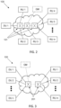
- Figs. 2-3 illustrates examples of simplified network architectures for a fronthaul network 100 in a Radio Access Network, RAN.
- the topology of the network architecture for the fronthaul network 100 in Fig. 2 may be referred to as a tree-like structure, while the topology of the network architecture for the packet-based fronthaul network 100 in Fig. 3 may be referred to as a dumbbell-like structure.
- the fronthaul network 100 in Figs. 2-3 may be any packet-based fronthaul network capable of carrying Time-Division Duplex, TDD, radio transmissions, i.e. this means that the fronthaul network fulfils the delay requirements for serving certain Radio Access Technologies, RATs, configured with TDD radio transmissions.
- the fronthaul network 100 in Fig. 2-3 may be implemented in a TDD-based RAN, such as, a NR or a LTE-TDD RAN, etc.
- the fronthaul network 100 in Figs. 2-3 may comprise one or more baseband processing units, DU1, DU2, ..., DUn, also referred to in some cases as a Digital Unit, DU.
- the baseband processing units DU1, DU2, ..., DUn may be connected to one or more RF processing units, RU1, RU2, ..., RUm, via a number of intermediate fronthaul network switches 101, 201.
- n and m is an integer depending on suitable deployment in the fronthaul network 100.
- the baseband processing units, DU1, DU2, ..., DUn, the RF processing units, RU1, RU2, ..., RUm, and the number of intermediate fronthaul network switches 101, 201 may be configured to communicate with each other over electrical or optical communications links in the fronthaul network 100.
- the one or more RF processing units, RU1, RU2, ..., RUm may be remote radio units, such as, e.g. RRUs/RRHs.
- the one or more RF processing units, RU1, RU2, ..., RUm may be indoor radio units or radio dots in a Radio Dot System, RDS, for an indoor system deployment.
- a grandmaster synchronization unit, GM may also be connected to the fronthaul network 100 in Figs. 2-3 .
- the grandmaster synchronization unit, GM may, for example, be a separate fronthaul network unit, one of the baseband processing unit, DU1, DU2, ..., DUn or even one of the RF processing units, RU1, RU2, ..., RUm, that has been elected, e.g. via a Best Master Clock Algorithm, BMCA, to be responsible for the timing exchange between the baseband processing units, DU1, DU2, ..., DUn and the RF processing units, RU1, RU2, ..., RUm.
- BMCA Best Master Clock Algorithm
- intermediate fronthaul network switches 101, 201 in between the baseband processing units, DU1, DU2, ..., DUn, and the RF processing units, RU1, RU2, ..., RUm, may be significantly higher.
- the intermediate fronthaul network switches 101, 201 will most prominently execute store-and-forward operations such that fronthaul data and control signalling, i.e. including synchronization messages, may traverse the fronthaul network 100.
- a delay will be introduced in the fronthaul network 100 that is at least partly dependent on the number of hops between the baseband processing units, DU1, DU2, ..., DUn, and the RF processing units, RU1, RU2, ..., RUm.
- the use of multiple intermediate fronthaul network switches may be required in the fronthaul network 100, for example, in indoor deployments where the RF processing units RU1, RU2, ..., RUm, are scattered in multiple floor levels.
- the intermediate fronthaul network switches 101, 201 may also comprise clocks or built-in uncertainties that may contribute to the overall delay experienced by a data packet, for example, a clock having a high frequency offsets or implementation specific indeterminacies in their switch fabric or forwarding engine, etc. This contribution to the overall delay, however, is normally relatively small in comparison.
- a significant reason behind the overall delay or PDV in the fronthaul network 100 is that the synchronization messages in the fronthaul network 100 are competing for the same outbound link in each intermediate fronthaul network switch 101, 201 as the ordinary data generated by the baseband processing units, DU1, DU2, ..., DUn in the DL direction and the RF processing units, RU1, RU2, ..., RUm in the UL direction.
- each of the RF processing units, RU1, RU2, ..., RUm, and the baseband processing units, DU1, DU2, ..., DUn comprises GPS modules from which to extract accurate timing, there will always be some level of synchronization due to the TDD system under consideration; that is, different cells must e.g. at least respect their guard times so as to avoid inter-cell interference.
- first fronthaul network unit may refer to any one of the baseband processing units, DU1, DU2, ..., DUn, or the RF processing units, RU1, RU2, ..., RUm, operating as a slave unit or slave clock unit in respect to a grandmaster synchronization unit, GM, operating as master unit or master clock unit.
- second fronthaul network unit may refer to any fronthaul network unit in the fronthaul network that operates as master unit or master clock unit, such as, the grandmaster synchronization unit, GM.
- the "first fronthaul network unit” may also be referred to as a PTP slave, and the "second fronthaul network unit” as a PTP master.
- a fronthaul network when carrying radio content for TDD systems, exhibits a similar periodic utilization pattern as that of the radio or air interface.
- the traffic characteristics generated by multiple baseband processing units may be observed to have a periodicity similar to that of the air radio interface of the remote network units.
- the DL traffic in the packet-based fronthaul network shows a TDD pattern where the links essentially are utilized in half-duplex mode even when signals are aggregated. Similar reasoning may also be applied to the UL direction from the remote network units.
- this dynamic TDD behaviour in the fronthaul network may be exploited to send packet-based synchronization messages, e.g. PTP messages, in periods of low utilization in the fronthaul network.
- PTP messages packet-based synchronization messages
- a fronthaul network unit operating as master or GM in the fronthaul network is configured to control the departure of the PTP messages to coincide with moments of low-activity in the fronthaul network, mainly caused by the TDD cycle; that is, the PTP messages may be transmitted in time periods opposing the active transmit direction of the air radio interface.
- knowledge of the TDD cycle of the Radio Access Technology, RAT may be used in the fronthaul network units to select adequate transmit opportunities for PTP messages in the fronthaul network.
- the master or GM may need to first coordinate the transmissions with the basebands processing unit and the RF processing units.
- commercially available GMs are used. These GMs are typically independent components which are not embedded in any of the baseband processing units or RF processing units. In these situations, the incorporation of such an independent GMs means that there is no or severely limited control over the PTP implementation in the fronthaul network, except perhaps from limited configuration parameters.
- solutions that may be implemented only at the slave units, or PTP slaves, in the fronthaul network may be considered more advantageous to operators of the fronthaul networks.
- a PTP slave is connected to legacy equipment, e.g. a master timing source from a third party, such as, a third party master unit or GM, in a fronthaul network.
- Packet selection may, for example, comprise selecting, from a set of observations, the observation with the minimum amount of delay, calculated over a finite observation window. In other words, selecting, from a window of N observations, the one PTP message with the smallest delay or most frequent delay value.
- Another approach to improve synchronization performance from the side of the slave unit is to implement packet filtering, whereby the slave unit extracts some derived value from an observation window, such as, e.g. a mean delay, a median delay, a mean time offset, etc.
- Model-based approaches such as, e.g.
- Kalman filters or Least-Squares Estimations may also be used in the slave unit to complement such filtering techniques, wherein some underlying dynamic of the synchronization system is taken into account in the process of extracting the derived value from the observation window.
- some underlying dynamic of the synchronization system is taken into account in the process of extracting the derived value from the observation window.
- one of the main disadvantages common to all approaches based on packet selection or packet filtering at the slave unit is the fact that the operator of the fronthaul network may have no control of the rate or instants when the PTP messages are sent by the master unit or GM. In general, the slave unit has no control or even knowledge about the other data traffic in the fronthaul network. This leads to solutions that are limited to operating over statistics of the delay distribution, but not being able to alter it.
- a first fronthaul network unit is able to derive time intervals for which synchronization messages have a low or high risk of competition with other fronthaul data traffic across the fronthaul network.
- the fronthaul network node is able to process timing information (e.g. one-way delay observations) provided by the synchronization messages according to their susceptibility to delay variation, i.e. depending on which of the first and/or second sets synchronization messages belongs to. This will provide more accurate synchronization information at the first fronthaul network unit with which the first fronthaul network unit may synchronize its clock.
- timing information e.g. one-way delay observations
- any fronthaul connected network unit acting as a PTP slave such as, any baseband processing unit or RF processing unit, e.g. remote radio unit, RF node, radio dot system entity, etc.
- the improved synchronization performance may be achieved without requiring any changes to any fronthaul standard or GM implementation, and when using non-PTP aware switches in the fronthaul network.
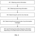
- Fig. 4 is an illustrated example of actions or operations which may be taken by the first fronthaul network unit RU1, RU2, ..., RUm; DU1, DU2, ..., DUn in the fronthaul network 100.
- the first fronthaul network unit RU1, RU2, ..., RUm; DU1, DU2, ..., DUn may be any type of fronthaul network unit acting as a slave unit in regards to synchronization of its time and frequency information.
- the first fronthaul network unit may, in some embodiments, be any one of a Radio Frequency, RF, processing unit RU1, RU2, ..., RUm or a baseband processing unit DU1, DU2, ..., DUn.
- the method may comprise the following actions.
- the first fronthaul network unit RU1, RU2, ..., RUm; DU1, DU2, ..., DUn obtains control information indicating uplink, UL, and downlink, DL, time periods for the TDD radio transmissions over a radio interface. This enables information regarding the timing of communications in the fronthaul network 100 corresponding to the TDD behaviour of the radio communications over the radio interface of the fronthaul network unit RU1, RU2, ..., RUm; DU1, DU2, ..., DUn in the fronthaul network 100 to be derived by the first fronthaul network unit RU1, RU2, ..., RUm; DU1, DU2, ..., DUn.
- the obtained control information may comprise one or more of: time slot format sequence information for the radio interface (such as, e.g. NR slot format in use).
- TDD configuration information for the radio interface such as, e.g. LTE-TDD subframe configuration information
- control information indicating points in time where a switch between UL and DL transmissions over the radio interface such as, e.g. explicit notification in the fronthaul control plane traffic of a TDD transmit direction change or switch).
- the obtained control information may indicate a NR slot format sequence, such as, e.g. DDDSU (i.e. a sequence of three downlink slots, followed by a slot where a transmit direction switch occurs and an uplink slot).
- the obtained control information may also comprise the slot format number for each of the slots in the sequence.
- this means that the obtained control information may indicate the TDD configuration for an LTE-TDD system, such as, e.g. configuration 2, DL:UL 4:1.
- the obtained control information may indicating a time where the TDD DL-UL or UL-DL switch point is.
- the control information may be set relative to a frame or slot start time point or another arbitrary reference point.
- the obtained control information may be provided by in a control message from the second fronthaul network unit GM; DU1, DU2, ..., DUn.
- periodic control messages may be transmitted comprising detailed information about when, inside a subframe or if ever, a DL-UL or UL-DL switch may occur. This may also apply to both CPRI or eCPRI which may carry this type of message in some form.
- Another example of such a control message may be a TDD switch point message.
- the TDD switch point message may, for example, carry information about whether the switch is a DL-UL or a UL-DL, as well as, a timestamp in units of a sample period with the beginning of a radio frame taken as time 0. In this case, it should be noted that this is not the HW timestamp that the PHY layer adds, but rather an indication of when (e.g. in "presentation time” or "air time”) the switch will occur.
- the fronthaul network 100 is full-duplex. This means that fronthaul data and control signalling, i.e. including packet-based synchronization messages, may be simultaneously transmitted in the UL and DL direction across the fronthaul network 100.
- the packet-based synchronization messages used in the fronthaul network 100 are timestamped data packets according to a packet-based synchronization protocol.
- the packet-based synchronization messages may be synchronization messages as defined in the Precision Time Protocol, PTP, such as, sync-, follow -up-, delay request- or delay response messages.
- the fronthaul network unit RU1, RU2, ..., RUm; DU1, DU2, ..., DUn also obtains local timing information in the first fronthaul network unit indicating the actual timing of the TDD radio transmissions over the fronthaul network 100.
- the local observation of this timing information allows the first fronthaul network unit RU1, RU2, ..., RUm; DU1, DU2, ..., DUn to, for example, accurately position a synchronization message in a received synchronization message streams from the second fronthaul network unit GM; DU1, DU2, ..., DUN and achieve more specific real-time timing information for the synchronization messages. For example, once the first fronthaul network unit RU1,
- RU2, ..., RUm; DU1, DU2, ..., DUn has obtained the control information in Action 401, e.g. that DL radio transmissions are due every 5ms (e.g. with a DDDSU scheme), the first fronthaul network unit RU1, RU2, ..., RUm; DU1, DU2, ..., DUn may still need to determine how much time there is from now, e.g. as given by the local clock time value, until the start of the DL radio transmission.
- the obtained local timing information may comprise one or more of: a local clock time value (e.g. a current value of an Real-Time Clock, RTC); a local I/Q sample count; a timing strobe indicating a frame or slot start; a sample, slot, subframe or frame counter for incoming data-packets over the fronthaul network 100; a first symbol indicator for incoming data-packets over the fronthaul network 100.
- the obtained information used by the first fronthaul network unit RU1, RU2, ..., RUm; DU1, DU2, ..., DUn may depend on which kind of information is most efficient to use for a specific implementation or situation.
- the first fronthaul network unit RU1, RU2, ..., RUm; DU1, DU2, ..., DUn determines, based on the obtained control and local timing information, fronthaul DL time intervals during which there are no TDD radio transmissions transferred between the first and second fronthaul network unit in the fronthaul DL direction, and fronthaul UL time intervals during which there are no TDD radio transmissions transferred between the first and second fronthaul network unit in the fronthaul UL direction.
- the first fronthaul network unit RU1, RU2, ..., RUm; DU1, DU2, ..., DUn derives information regarding the timing of communications in the fronthaul network 100 corresponding to the TDD behaviour of the radio communications over the radio interface of the first fronthaul network unit RU1, RU2, ..., RUm; DU1, DU2, ..., DUn.
- the first fronthaul network unit RU1, RU2, ..., RUm; DU1, DU2, ..., DUn determines time intervals for which synchronization messages have a lower and higher risk of competition with other fronthaul data traffic across the fronthaul network compared with each other.
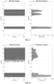
- Figs. 5-6 This is exemplified in Figs. 5-6 .
- the timing of signaling in both the UL and DL transmit directions is illustrated, but also the timing of the signalling on the radio interface.
- a series of time instances are referenced in Figs. 5-6 , wherein the subscript i is used to denote the i-th time instance:
- Figs. 5-6 shows schematic illustrations presenting an example of time intervals, such as, e.g. C i to A i +1 for DL and H i -1 to F i for UL, in which packet-based synchronization messages in the fronthaul network 100, such as, e.g. PTP Sync messages or PTP Delay_Req messages, respectively, may be transmitted in the DL/UL direction with lower competition in the fronthaul network 100 from other fronthaul data traffic.
- packet-based synchronization messages in the fronthaul network 100 such as, e.g. PTP Sync messages or PTP Delay_Req messages, respectively, may be transmitted in the DL/UL direction with lower competition in the fronthaul network 100 from other fronthaul data traffic.
- the first fronthaul network unit RU1, RU2, ..., RUm; DU1, DU2, ..., DUn has determined the time intervals in Action 403, the first fronthaul network unit RU1, RU2, ..., RUm; DU1, DU2, ..., DUn determines first sets of synchronization messages that has been transferred between the first and second fronthaul network unit within the determined fronthaul DL and UL time intervals, and second sets of synchronization messages that has been transferred between the first and second fronthaul network unit outside the determined fronthaul DL and UL time intervals.
- the first fronthaul network unit RU1, RU2, ..., RUm; DU1, DU2, ..., DUn may determine which synchronization messages that are received during a time of lower risk of competition with other fronthaul data traffic across the fronthaul network, and determine which synchronization messages that are received during a time of higher risk of competition with other fronthaul data traffic across the fronthaul network; then, the first fronthaul network unit RU1, RU2, ..., RUm; DU1, DU2, ..., DUn groups the synchronization message in different sets accordingly.
- the first fronthaul network unit RU1, RU2, ..., RUm; DU1, DU2, ..., DUn, operating a PTP slave clock may, for example, classify the PTP messages in relation to the determined fronthaul DL and UL time intervals.
- a synchronization message transmitted from the second fronthaul network unit GM; DU1, DU2, ..., DUN such as, e.g. PTP Sync-messages, that is received by the first fronthaul network unit RU1, RU2, ..., RUm; DU1, DU2, ..., DUn, in any of the dashed transmit opportunities in Fig. 5 may be determined to be comprised in a first set A of synchronization messages, i.e.
- a synchronization message transmitted from the second fronthaul network unit GM; DU1, DU2, ..., DUN such as, e.g.
- PTP Sync-messages that is received by the first fronthaul network unit RU1, RU2, ..., RUm; DU1, DU2, ..., DUn, in any of the non-dashed transmit opportunities in Fig. 5 may be determined to be comprised in a second set B of synchronization messages, i.e. Accordingly, the first set A indicates synchronization messages that would experience low downlink competition in the network, while Set B indicates synchronization messages that would experience higher downlink competition.
- a synchronization message to the second fronthaul network unit GM; DU1, DU2, ..., DUN such as, e.g. PTP Delay_Req-messages, that is transmitted from the first fronthaul network unit RU1, RU2, ..., RUm; DU1, DU2, ..., DUn in any of the dashed transmit opportunities in Fig. 6 may be determined to be comprised in a first set A of synchronization messages, i.e.
- a synchronization message to the second fronthaul network unit GM; DU1, DU2, ..., DUN such as, e.g.
- PTP Delay_Req-messages that is transmitted from the first fronthaul network unit RU1, RU2, ..., RUm; DU1, DU2, ..., DUn in any of the non-dashed transmit opportunities in Fig. 6 may be determined to be comprised in a second set B of synchronization messages, i.e. Accordingly, the first set A indicates synchronization messages that would experience low uplink competition in the network, while Set B indicates synchronization messages that would experience higher uplink competition.
- ms and sm for the first and second sets of synchronization messages here denotes the master-to-slave and slave-to-master directions, while w denotes an observation window during which synchronization messages are received. It should also be noted that even though about 16 transmit opportunities for synchronization messages per transmission pattern as depicted in the Figs. 5-6 is a realistic number, this is merely made for illustrative purposes and should not be considered limiting since the illustrations in Figs. 5-6 are not drawn to scale.
- a single two-way exchange as depicted in Fig. 1 may therefore have a PTP Sync message from either set A or B, and a PTP Delay_Req message from either set A or B as well, yielding four possible "labels" for the exchange, i.e. AA, AB, BA, BB.
- the first fronthaul network unit RU1, RU2, ..., RUm; DU1, DU2, ..., DUn synchronizes, based on the synchronization messages, time and/or frequency information in the first fronthaul network unit depending on which of the first and/or second sets the synchronization messages belongs to.
- the first fronthaul network unit RU1, RU2, ..., RUm; DU1, DU2, ..., DUn may perform the synchronization of the time and/or frequency information based on synchronization messages that belongs to the first sets of synchronization messages. This means that the first fronthaul network unit RU1, RU2, ..., RUm; DU1, DU2, ..., DUn may synchronize the time and/or frequency information using a set of synchronization message that provide a comparatively low delay variation among its delay observations as compared to using each of the synchronization messages received.
- the first fronthaul network unit RU1, RU2, ..., RUm; DU1, DU2, ..., DUn may perform the synchronization of the time and/or frequency information based on a time offset x ⁇ that is estimated using the synchronization messages that belongs to the first sets of synchronization messages. If, for example, only AA exchanges are considered, that is, two-way exchanges wherein both the PTP Sync message belong to set and the PTP Delay_Req message belong to set then the time offset x ⁇ may, for example, be estimated for each observation window w according to Eq.
- the first fronthaul network unit RU1, RU2, ..., RUm; DU1 may optionally estimate the time offset x ⁇ based on a calculation using one or more time delays in the fronthaul network 100 for synchronization messages that belongs to the first sets of synchronization messages. According to one example, this may be performed by disregarding all synchronization messages belonging to Set B for each direction and only considering the synchronization messages belonging to Set A for each direction, that is, estimating the time offset x ⁇ for each observation window w according to Eq. 2:
- the first fronthaul network unit RU1, RU2, ..., RUm; DU1, DU2, ..., DUn may further perform the synchronization of the time and/or frequency information based on one or more synchronization messages that belongs to the second sets of synchronization messages.
- the first fronthaul network unit RU1, RU2, ..., RUm; DU1, DU2, ..., DUn may use synchronization messages from the different sets, but take into account the knowledge that the synchronization messages from the different sets may have significantly varying delay variations compared to one another.
- the first fronthaul network unit RU1, RU2, ..., RUm; DU1, DU2, ..., DUn may perform the synchronization of the time and/or frequency information based on synchronization messages that belongs to both the first and second sets of synchronization messages by filtering the synchronization messages using a model-based filter, wherein the model-based filter is adapted to the difference in delay variance between the one or more synchronization messages that belongs to the second sets B w ms , B w sm of synchronization messages and the synchronization messages that belongs to the first sets of synchronization messages.
- the model-based filter is adapted to the difference in delay variance between the one or more synchronization messages that belongs to the second sets B w ms , B w sm of synchronization messages and the synchronization messages that belongs to the first sets of synchronization messages.
- AA, AB, BA, BB may be used in designing a model-based filter.
- the membership of the synchronization messages to the different sets A and B may, for example, be used to specify a regressor matrix and noise co-variance properties of the synchronization messages in a least-square formulation that may be used by the model-filter.
- the slave i.e. the first fronthaul network unit RU1, RU2, ..., RUm; DU1, DU2, ..., DUn, has access to four timestamps t 1 , t 2 , t 3 , t 4 (or sets of said timestamps).
- the embodiments outlined above for filtering the synchronization messages may be used by the first fronthaul network unit RU1, RU2, ..., RUm; DU1, DU2, ..., DUn in both directions to, for example, obtain good master-to-slave and slave-to-master delay estimates. This may be performed prior to, for example, estimating a time offset adjustment.
- the first fronthaul network unit RU1, RU2, ..., RUm; DU1, DU2, ..., DUn may perform the synchronization of the time and/or frequency information by updating a Real-Time Clock, RTC, in the first fronthaul network unit.
- RTC Real-Time Clock
- the first fronthaul network unit RU1, RU2, ..., RUm; DU1, DU2, ..., DUn updates its local clock, i.e. its PTP slave clock.
- some embodiments herein refer to time offset estimation, it may easily be applied to other synchronization issues, such as, e.g. frequency offset estimation.
- Fig. 7 shows a plot diagram indicating measurements of one-way delays from a master clock unit, such as, the second fronthaul network unit GM; DU1, DU2, ..., DUN, to a slave clock unit, such as, the first fronthaul network unit RU1, RU2, ..., RUm; DU1, DU2, ..., DU, that may occur in a fronthaul network 100.
- a master clock unit such as, the second fronthaul network unit GM; DU1, DU2, ..., DUN
- a slave clock unit such as, the first fronthaul network unit RU1, RU2, ..., RUm; DU1, DU2, ..., DU
- FIG. 8 shows a plot diagram indicating measurements of one-way delays from a slave clock unit, such as, the first fronthaul network unit RU1, RU2, ..., RUm; DU1, DU2, ..., DU, to a master clock unit, such as, the second fronthaul network unit GM; DU1, DU2, ..., DUN, that may occur in a fronthaul network 100.
- a slave clock unit such as, the first fronthaul network unit RU1, RU2, ..., RUm; DU1, DU2, ..., DU
- a master clock unit such as, the second fronthaul network unit GM; DU1, DU2, ..., DUN
- the dataset was obtained over a four-hop tree topology, i.e. the first switch is connected to one baseband node, e.g. DU1 in Fig. 2 , while the last is connected to two RF nodes or units, e.g. RU4 and RU5 in Fig. 2 .
- the two RF nodes compete for the outbound link in the last switch.
- the intermediate switches were not configured to prioritize sync traffic, therefore queueing delays may be substantial. All links are 1Gbps Ethernet, carrying TDD fronthaul traffic besides PTP packets. Further, the statistics of both low and high competition portions of the TDD cycle were calculated on the measured data, and later used to generate noise samples in the simulations, i.e. Gaussian noise with different mean and variances.
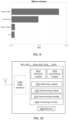
- Fig. 9 shows a diagram indicating time offset estimation performance in terms of Mean-Squared Error, MSE, of different time offset estimators using simulations based on the measurements referred to in Figs. 7-8 .
- the uppermost time offset estimator in Fig. 9 uses a sample mean (calculating the average delay in each direction) which takes all synchronization messages into account, while the time offset estimator below the uppermost time offset estimator in Fig. 9 uses a sample minimum (calculating the smallest observed delay asymmetry) which takes all synchronization messages into account.
- the two remaining time offset estimators shown in Fig. 9 represent estimators according to embodiments herein.
- the uppermost of these time offset estimators uses a sample mean that calculates the average delay in each direction only over PTP exchanges in which both synchronization messages belong to set A.
- the other time offset estimator is a Least Squares, LS, time offset estimator where the matrix for each direction is derived from the set membership of the synchronization messages, as described in some embodiments above.
- Fig. 9 illustrates some of the advantages of the embodiments described herein by indicating that labelling the messages and taking the labels into consideration when performing packet filtering according to the embodiments described herein will lead to improved time offset estimation performance.
- time offset estimators For the time offset estimation performance in Fig. 9 , some simulation assumptions where made, such as, e.g. correct labelling of each PTP message into Set A or Set B, 128 PTP messages/second in each direction are transmitted, the time offset estimators all operate in batches of 128 synchronization messages, and no side traffic (TDD) information is considered by some of the time offset estimators, etc.
- TDD side traffic
- a first fronthaul network unit RU1, RU2, ..., RUm, DU1, DU2, ..., DUn for synchronizing with a second fronthaul network unit GM; DU1, DU2, ..., DUn across a fronthaul network 100 carrying Time-Division Duplex, TDD, radio transmissions
- the first fronthaul network unit RU1, RU2, ..., RUm, DU1, DU2, ..., DUn may comprise the following arrangement depicted in Fig 10
- Fig 10 shows a schematic block diagram of embodiments of a first fronthaul network unit RU1, RU2, ..., RUm, DU1, DU2, ..., DUn.
- first fronthaul network unit RU1, RU2, ..., RUm, DU1, DU2, ..., DUn described herein may be considered as independent embodiments or may be considered in any combination with each other to describe nonlimiting examples of the example embodiments described herein.
- the first fronthaul network unit RU1, RU2, ..., RUm, DU1, DU2, ..., DUn may comprise processing circuitry 1010 and a memory 1020.
- the processing circuitry 1010 may also comprise a receiving module 1011 and a transmitting module 1012.
- the receiving module 1011 and the transmitting module 1012 may be configured to communicate and perform transmissions over the packet-based fronthaul network 100, for example, transmit and receive payload data for TDD radio transmissions, and transmit and receive synchronization messages, e.g. PTP messages.
- the receiving module 1011 and the transmitting module 1012 may also form part of a single transceiver.
- first fronthaul network unit RU1, RU2, ..., RUm, DU1, DU2, ..., DUn may be provided by the processing circuitry 1010 executing instructions stored on a computer-readable medium, such as, e.g. the memory 1020 shown in Fig. 10 .
- Alternative embodiments of the first fronthaul network unit RU1, RU2, ..., RUm, DU1, DU2, ..., DUn may comprise additional components, such as, for example, an obtaining module 1013, a determining module 1014, and a synchronization module 1015, each responsible for providing its respective functionality necessary to support the embodiments described herein.
- the first fronthaul network unit RU1, RU2, ..., RUm, DU1, DU2, ..., DUn or processing circuitry 1010 is configured to, or may comprise the obtaining module 1013 configured to, obtain control information indicating uplink, UL, and downlink, DL, time periods for the TDD radio transmissions over a radio interface.
- the first fronthaul network unit RU1, RU2, ..., RUm, DU1, DU2, ..., DUn or processing circuitry 1010 is also configured to, or may comprise the obtaining module 1013 configured to, obtain local timing information in the first fronthaul network unit indicating the actual timing of the TDD radio transmissions over the fronthaul network 100.
- first fronthaul network unit RU1, RU2, ..., RUm, DU1, DU2, ..., DUn or processing circuitry 1010 is also configured to, or may comprise the determining module 1014 configured to, determine, based on the obtained control and local timing information, fronthaul DL time intervals during which there are no TDD radio transmissions transferred between the first and second fronthaul network unit in the fronthaul DL direction, and fronthaul UL time intervals during which there are no TDD radio transmissions transferred between the first and second fronthaul network unit in the fronthaul DL direction.
- the first fronthaul network unit RU1, RU2, ..., RUm, DU1, DU2, ..., DUn or processing circuitry 1010 is also configured to, or may comprise the determining module 1014 configured to, determine first sets of synchronization messages that has been transferred between the first and second fronthaul network unit within the determined fronthaul DL and UL time intervals, and second sets of synchronization messages that has been transferred between the first and second fronthaul network unit outside the determined fronthaul DL and UL time intervals.
- first fronthaul network unit RU1, RU2, ..., RUm, DU1, DU2, ..., DUn or processing circuitry 1010 is also configured to, or may comprise the synchronization module 1015 configured to, synchronize, based on the synchronization messages, time and/or frequency information in the first fronthaul network unit depending on which of the first and/or second sets the synchronization messages belongs to.
- the first fronthaul network unit RU1, RU2, ..., RUm, DU1, DU2, ..., DUn or processing circuitry 1010 may be configured to, or may comprise the synchronization module 1015 configured to, synchronize the time and/or frequency information based on synchronization messages that belongs to the first sets of synchronization messages. Also, in some embodiments, the first fronthaul network unit RU1, RU2, ..., RUm, DU1, DU2, ..., DUn or processing circuitry 1010 may be configured to, or may comprise the synchronization module 1015 configured to, synchronize the time and/or frequency information based on a time offset estimated using the synchronization messages that belongs to the first sets of synchronization messages.
- the first fronthaul network unit RU1, RU2, ..., RUm, DU1, DU2, ..., DUn or processing circuitry 1010 may be configured to, or may comprise the synchronization module 1015 configured to, estimate the timing offset as a mean or median value of time delays in the fronthaul network 100 for the synchronization messages that belongs to the first sets of synchronization messages.
- the first fronthaul network unit RU1, RU2, ..., RUm, DU1, DU2, ..., DUn or processing circuitry 1010 may also be configured to, or may comprise the synchronization module 1015 configured to, synchronize the time and/or frequency information based on one or more synchronization messages that belongs to the second sets of synchronization messages.
- the first fronthaul network unit RU1, RU2, ..., RUm, DU1, DU2, ..., DUn or processing circuitry 1010 may also be configured to, or may comprise the synchronization module 1015 configured to, synchronize the time and/or frequency information based on synchronization messages that belongs to both the first and second sets of synchronization messages by filtering the synchronization messages using a model-based filter, wherein the model-based filter is adapted to the difference in delay variance between the one or more synchronization messages that belongs to the second sets of synchronization messages and the synchronization messages that belongs to the first sets of synchronization messages.
- the obtained control information may comprise one or more of: a time slot format sequence information of the fronthaul network 100, a TDD configuration information of the fronthaul network 100, and control information indicating points in time where a switch between UL and DL transmissions is to be performed in the fronthaul network 100.
- the obtained local timing information may comprise one or more of: a local clock time value, a local I/Q sample count, a timing strobe indicating a frame or slot start, a sample, slot, subframe or frame counter for incoming data-packets over the fronthaul network 100, and a first symbol indicator for incoming data-packets over the fronthaul network 100.
- the first fronthaul network unit RU1, RU2, ..., RUm, DU1, DU2, ..., DUn or processing circuitry 1010 may be configured to, or may comprise the synchronization module 1015 configured to, synchronize the time or frequency information by updating a Real-Time Clock, RTC, in the first fronthaul network unit RU1, RU2, ..., RUm, DU1, DU2, ..., DUn.
- the fronthaul network 100 is full-duplex and the synchronization messages are timestamped data packets according to a packet-based synchronization protocol, such as, e.g. PTP.
- the first fronthaul network unit RU1, RU2, ..., RUm, DU1, DU2, ..., DUn may be any type of fronthaul network unit that acts as a slave unit in accordance with the packet-based synchronization protocol, such as, e.g. a PTP slave unit.
- the embodiments of the first fronthaul network unit RU1, RU2, ..., RUm, DU1, DU2, ..., DUn for synchronizing with a second fronthaul network unit GM; DU1, DU2, ..., DUN across a fronthaul network 100 carrying TDD radio transmissions, described above may be implemented through one or more processors, such as the processing circuitry 1010 in the first fronthaul network unit RU1, RU2, ..., RUm, DU1, DU2, ..., DUn depicted in Fig. 10 , together with computer program code for performing the functions and actions of the embodiments herein.
- the program code mentioned above may also be provided as a computer program product, for instance in the form of a data carrier carrying computer program code or code means for performing the embodiments herein when being loaded into the processing circuitry 1010 in the first fronthaul network unit RU1, RU2, ..., RUm, DU1, DU2, ..., DUn.
- the data carrier, or computer readable medium may be one of an electronic signal, optical signal, radio signal, or computer-readable storage medium.
- the computer program code may e.g.
- the modules of the first fronthaul network unit RU1, RU2, ..., RUm, DU1, DU2, ..., Dun may in some embodiments be implemented as computer programs stored in memory, e.g. in the memory modules 1020 in Figure 10 , for execution by processors or processing modules, e.g. the processing circuitry 1010 of Figure 10 .
- processing circuitry 1010 and the memory 1020 described above may refer to a combination of analog and digital circuits, and/or one or more processors configured with software and/or firmware, e.g. stored in a memory, that when executed by the one or more processors such as the processing circuitry 1020 perform as described above.
- processors as well as the other digital hardware, may be included in a single application-specific integrated circuit (ASIC), or several processors and various digital hardware may be distributed among several separate components, whether individually packaged or assembled into a system-on-a-chip (SoC).
- ASIC application-specific integrated circuit
- SoC system-on-a-chip
- a computer-readable medium may include removable and non-removable storage devices including, but not limited to, Read Only Memory (ROM), Random Access Memory (RAM), compact discs (CDs), digital versatile discs (DVD), etc.
- program modules may include routines, programs, objects, components, data structures, etc. that perform particular tasks or implement particular abstract data types.
- Computer-executable instructions, associated data structures, and program modules represent examples of program code for executing steps of the methods disclosed herein. The particular sequence of such executable instructions or associated data structures represents examples of corresponding acts for implementing the functions described in such steps or processes.
Landscapes
- Engineering & Computer Science (AREA)
- Signal Processing (AREA)
- Computer Networks & Wireless Communication (AREA)
- Mobile Radio Communication Systems (AREA)
- Small-Scale Networks (AREA)
Claims (15)
- Procédé réalisé par une première unité de réseau fronthaul (RU1, RU2, ..., RUm ; DU1, DU2, ..., DUn) pour la synchronisation avec une deuxième unité de réseau fronthaul (GM ; DU1, DU2, ..., DUn) sur un réseau fronthaul (100) portant des transmissions radio à duplexage par répartition dans le temps, TDD, le procédé comprenant :l'obtention (401) d'informations de commande indiquant des périodes de temps de liaison montante, UL, et de liaison descendante, DL, pour les transmissions radio TDD sur une interface radio ;l'obtention (402) d'informations de temporisation locale dans la première unité de réseau fronthaul indiquant la temporisation réelle des transmissions radio TDD sur le réseau fronthaul (100) ;la détermination (403), sur la base des informations de commande et de temporisation locale obtenues, d'intervalles de temps DL fronthaul (Ci, A i+1) au cours desquels il n'y a pas de transmission radio TDD transférée entre les première et deuxième unités de réseau fronthaul dans la direction DL fronthaul, et d'intervalles de temps UL fronthaul (H i-1, Fi ) au cours desquels il n'y a pas de transmission radio TDD transférée entre les première et deuxième unités de réseau fronthaul dans la direction UL fronthaul ; etla détermination (404) de premiers ensembles (

 la synchronisation (405), sur la base des messages de synchronisation, d'informations de temps et/ou de fréquence dans la première unité de réseau fronthaul en fonction de ceux parmi les premiers et/ou deuxièmes ensembles (
- Procédé selon la revendication 1, dans lequel la synchronisation (405) est basée sur :- des messages de synchronisation qui appartiennent aux premiers ensembles (
 - un décalage de temps (x̂) qui est estimé à l'aide des messages de synchronisation qui appartiennent aux premiers ensembles (
- Procédé selon la revendication 2, dans lequel le décalage de temps (x̂) est estimé sur la base d'un calcul à l'aide d'un ou plusieurs retards temporels dans le réseau fronthaul (100) pour des messages de synchronisation qui appartiennent aux premiers ensembles (

- Procédé selon la revendication 2, dans lequel la synchronisation (405) est en outre basée sur :- un ou plusieurs messages de synchronisation qui appartiennent aux deuxièmes ensembles (
 - des messages de synchronisation qui appartiennent à chacun des premiers et deuxièmes ensembles (

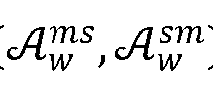
- Procédé selon l'une quelconque des revendications 1 à 4, dans lequel les informations de commande obtenues peuvent comprendre une ou plusieurs parmi :- des informations de séquence de format de créneau temporel pour l'interface radio ;- des informations de configuration de TDD pour l'interface radio ; et- des informations de commande indiquant des points temporels de commutation entre des transmissions UL et DL sur l'interface radio.
- Procédé selon l'une quelconque des revendications 1 à 5, dans lequel les informations de temporisation locale obtenues peuvent comprendre un ou plusieurs parmi :- une valeur de temps d'horloge locale ;- un compte d'échantillons I/Q local ;- une impulsion d'activation de temporisation indiquant un début de trame ou de créneau ;- un compteur d'échantillons, de créneaux, de sous-trames ou de trames pour des paquets de données entrants sur le réseau fronthaul (100) ;- un premier indicateur de symbole pour des paquets de données entrants sur le réseau fronthaul (100) ; et- dans lequel la synchronisation (405) comprend en outre la mise à jour d'une horloge en temps réel, RTC, dans la première unité de réseau fronthaul.
- Procédé selon l'une quelconque des revendications 1 à 6, dans lequel le réseau fronthaul (100) est en duplex intégral, et les messages de synchronisation sont des paquets de données horodatés selon un protocole de synchronisation basée sur paquets ; oudans lequel la première unité de réseau fronthaul (RU1, RU2, ..., RUm ; DU1, DU2, ..., DUn) est n'importe quel type d'unité de réseau fronthaul agissant comme unité esclave en ce qui concerne la synchronisation de ses informations de temps et de fréquence ; oudans lequel la première unité de réseau est l'une parmi une unité de traitement de radiofréquence, RF, (RU1, RU2, ..., RUm) ou une unité de traitement de bande de base (DU1, DU2, ..., DUn).
- Première unité de réseau fronthaul (RU1, RU2, ..., RUm ; DU1, DU2, ..., DUn) pour la synchronisation avec une deuxième unité de réseau fronthaul (GM ; DU1, DU2, ..., DUn) sur un réseau fronthaul (100) portant des transmissions radio à duplexage par répartition dans le temps, TDD, dans laquelle la première unité de réseau fronthaul (RU1, RU2, ..., RUm ; DU1, DU2, ..., DUn) est configurée pour :
obtenir des informations de commande indiquant des périodes de temps de liaison montante, UL, et de liaison descendante, DL, pour les transmissions radio TDD sur une interface radio, obtenir des informations de temporisation locale dans la première unité de réseau fronthaul indiquant la temporisation réelle des transmissions radio TDD sur le réseau fronthaul (100), déterminer, sur la base des informations de commande et de temporisation locale obtenues, des intervalles de temps DL fronthaul (Ci, A i+1) au cours desquels il n'y a pas de transmission radio TDD transférée entre les première et deuxième unités de réseau fronthaul dans la direction DL fronthaul, et des intervalles de temps UL fronthaul (Hi , F i+1) au cours desquels il n'y a pas de transmission radio TDD transférée entre les première et deuxième unités de réseau fronthaul dans la direction DL fronthaul, déterminer des premiers ensembles (
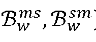

- Première unité de réseau fronthaul selon la revendication 8, configurée en outre pour synchroniser les informations de temps et/ou de fréquence sur la base :- de messages de synchronisation qui appartiennent aux premiers ensembles (
 - d'un décalage de temps (x̂) estimé à l'aide des messages de synchronisation qui appartiennent aux premiers ensembles (
- Première unité de réseau fronthaul selon la revendication 9, configurée en outre pour estimer le décalage de temps (x̂) comme une valeur moyenne ou médiane de retards temporels dans le réseau fronthaul (100) pour les messages de synchronisation qui appartiennent aux premiers ensembles (

- Première unité de réseau fronthaul selon la revendication 9, configurée en outre pour synchroniser les informations de temps et/ou de fréquence sur la base :- d'un ou plusieurs messages de synchronisation qui appartiennent aux deuxièmes ensembles (
 - de messages de synchronisation qui appartiennent à la fois aux premiers et deuxièmes ensembles (


- Première unité de réseau fronthaul selon l'une quelconque des revendications 8 à 11, dans laquelle les informations de commande obtenues peuvent comprendre une ou plusieurs parmi :- des informations de séquence de format de créneau temporel du réseau fronthaul (100) ;- des informations de configuration de TDD du réseau fronthaul (100) ; et- des informations de commande indiquant des points temporels auxquels une commutation entre des transmissions UL et DL doit être réalisée dans le réseau fronthaul (100).
- Première unité de réseau fronthaul selon l'une quelconque des revendications 8 à 12, dans laquelle les informations de temporisation locale obtenues peuvent comprendre un ou plusieurs parmi :- une valeur de temps d'horloge locale ;- un compte d'échantillons I/Q local ;- une impulsion d'activation de temporisation indiquant un début de trame ou de créneau ;- un compteur d'échantillons, de créneaux, de sous-trames ou de trames pour des paquets de données entrants sur le réseau fronthaul (100) ;- un premier indicateur de symbole pour des paquets de données entrants sur le réseau fronthaul (100) ; et- en outre configurée pour synchroniser les informations de temps ou de fréquence dans la première unité de réseau fronthaul (RU1, RU2, ..., RUm ; DU1, DU2, ..., DUn) par la mise à jour d'une horloge en temps réel, RTC.
- Première unité de réseau fronthaul selon l'une quelconque des revendications 8 à 13,- dans laquelle le réseau (100) est en duplex intégral, et les messages de synchronisation sont des paquets de données horodatés selon un protocole de synchronisation basée sur paquets ; ou- dans laquelle la première unité de réseau fronthaul (RU1, RU2, ..., RUm ; DU1, DU2, ..., DUn) est n'importe quel type d'unité de réseau fronthaul agissant comme unité esclave en ce qui concerne la synchronisation de ses informations de temps et de fréquence ; ou- dans laquelle la première unité de réseau est l'une parmi une unité de traitement de radiofréquence, RF, (RU1, RU2, ..., RUm) ou une unité de traitement de bande de base (DU1, DU2, ..., DUn) ;- comprenant un processeur (1010) et une mémoire (1020), dans laquelle la mémoire (1020) contient des instructions exécutables par le processeur (1010).
- Programme informatique comprenant des instructions qui, lorsqu'elles sont exécutées sur au moins un processeur (1010), amènent l'au moins un processeur (1010) à réaliser le procédé selon l'une quelconque des revendications 1 à 7.
Applications Claiming Priority (1)
| Application Number | Priority Date | Filing Date | Title |
|---|---|---|---|
| PCT/SE2020/050693 WO2022005350A1 (fr) | 2020-07-01 | 2020-07-01 | Unité de réseau fronthaul et procédé associé pour la synchronisation sur un réseau fronthaul |
Publications (3)
| Publication Number | Publication Date |
|---|---|
| EP4176540A1 EP4176540A1 (fr) | 2023-05-10 |
| EP4176540A4 EP4176540A4 (fr) | 2024-04-03 |
| EP4176540B1 true EP4176540B1 (fr) | 2025-06-18 |
Family
ID=79317823
Family Applications (1)
| Application Number | Title | Priority Date | Filing Date |
|---|---|---|---|
| EP20942495.1A Active EP4176540B1 (fr) | 2020-07-01 | 2020-07-01 | Unité de réseau fronthaul et procédé associé pour la synchronisation sur un réseau fronthaul |
Country Status (4)
| Country | Link |
|---|---|
| US (1) | US12414063B2 (fr) |
| EP (1) | EP4176540B1 (fr) |
| AR (1) | AR122813A1 (fr) |
| WO (1) | WO2022005350A1 (fr) |
Families Citing this family (4)
| Publication number | Priority date | Publication date | Assignee | Title |
|---|---|---|---|---|
| FR3119244A1 (fr) * | 2021-01-22 | 2022-07-29 | Orange | Traitement du délai pour une mesure de géolocalisation |
| US12538275B2 (en) * | 2021-12-21 | 2026-01-27 | Electronics And Telecommunications Research Institute | Method and apparatus for radio communication of time sensitive network |
| US20230362084A1 (en) * | 2022-05-09 | 2023-11-09 | Mellanox Technologies, Ltd. | Rational value rate limiter |
| EP4702783A1 (fr) * | 2023-04-24 | 2026-03-04 | Telefonaktiebolaget LM Ericsson (publ) | Entité de réseau pour une synchronisation sur un réseau fronthaul basé sur des paquets |
Family Cites Families (13)
| Publication number | Priority date | Publication date | Assignee | Title |
|---|---|---|---|---|
| US8976778B2 (en) * | 2010-04-21 | 2015-03-10 | Lsi Corporation | Time synchronization using packet-layer and physical-layer protocols |
| EP3435734B1 (fr) * | 2016-03-25 | 2021-04-21 | NTT DoCoMo, Inc. | Station de base et procédé de réglage de cellule |
| WO2018017468A1 (fr) * | 2016-07-18 | 2018-01-25 | Phluido, Inc. | Synchronisation d'unités radio dans des réseaux d'accès radio |
| US10382191B2 (en) * | 2016-11-30 | 2019-08-13 | Juniper Networks, Inc. | Efficient unicast signaling in a precision time protocol enabled packet network |
| EP3834513A1 (fr) * | 2018-08-08 | 2021-06-16 | Nokia Technologies Oy | Amélioration de synchronisation temporelle pour un groupe d'ue |
| US12608218B2 (en) * | 2018-09-26 | 2026-04-21 | Telefonaktiebolaget Lm Ericsson (Publ) | Methods and apparatus for modifying an allocation of virtualized processing resources for a digital unit based on timing feedback from a radio unit |
| US11265835B1 (en) * | 2019-06-12 | 2022-03-01 | Birket Ip Holdings, Inc. | Low skew synchronization of disparate wireless nodes in a pyrotechnic environment |
| US11411778B2 (en) * | 2019-07-12 | 2022-08-09 | XCOM Labs, Inc. | Time-division duplex multiple input multiple output calibration |
| US12335884B2 (en) * | 2019-10-22 | 2025-06-17 | Telefonaktiebolaget Lm Ericsson (Publ) | Network entity for synchronization over a packet-based fronthaul network |
| WO2021108630A1 (fr) * | 2019-11-26 | 2021-06-03 | Commscope Technologies Llc | Évitement de contention entre des paquets de synchronisation et des paquets en phase et en quadrature (iq) communiqués sur un réseau fronthaul d'un réseau d'accès radio |
| US12426045B2 (en) * | 2020-05-22 | 2025-09-23 | Indian Institute Of Technology Hyderabad (Iith) | Method and system for transferring data between distributed unit and radio unit |
| US12279156B2 (en) * | 2020-06-03 | 2025-04-15 | Mavenir Systems, Inc. | Traffic timing control for an open radio access network in a cloud radio access network system |
| US12231989B2 (en) * | 2021-04-13 | 2025-02-18 | Asocs Ltd. | High accuracy ORAN radio unit synchronization error estimation |
-
2020
- 2020-07-01 US US18/003,604 patent/US12414063B2/en active Active
- 2020-07-01 EP EP20942495.1A patent/EP4176540B1/fr active Active
- 2020-07-01 WO PCT/SE2020/050693 patent/WO2022005350A1/fr not_active Ceased
-
2021
- 2021-06-30 AR ARP210101830A patent/AR122813A1/es active IP Right Grant
Also Published As
| Publication number | Publication date |
|---|---|
| EP4176540A4 (fr) | 2024-04-03 |
| AR122813A1 (es) | 2022-10-05 |
| US20230239817A1 (en) | 2023-07-27 |
| EP4176540A1 (fr) | 2023-05-10 |
| WO2022005350A1 (fr) | 2022-01-06 |
| US12414063B2 (en) | 2025-09-09 |
Similar Documents
| Publication | Publication Date | Title |
|---|---|---|
| EP4176540B1 (fr) | Unité de réseau fronthaul et procédé associé pour la synchronisation sur un réseau fronthaul | |
| CN110475336B (zh) | 一种实现网络同步的方法及装置 | |
| US12335884B2 (en) | Network entity for synchronization over a packet-based fronthaul network | |
| US10321424B2 (en) | Methods and system for synchronizing nodes in a wireless network | |
| CN110431914B (zh) | 具有用户设备终端能力的远程射频头 | |
| CN115004794B (zh) | 一种用于参考信号时间同步与校准的方法 | |
| US11864139B2 (en) | Transmitting device, receiving device and methods performed therein for handling communication | |
| US9544863B2 (en) | Over-the-air synchronization for small cells in a wireless communication network | |
| CN109792703A (zh) | 基于参数集在同步操作和异步操作之间进行适配 | |
| CN111989960B (zh) | 针对ue侧行链路和/或上行链路通信的基于网络的时间同步的技术 | |
| CN102469571A (zh) | 一种在分布式基站系统中实现时延补偿的方法及系统 | |
| US20220039042A1 (en) | Methods, second node and apparatus for determining clock asynchronization | |
| WO2022157598A1 (fr) | Procédés et appareils destinés à l'estimation du temps aller-retour (rtt) entre récepteur (rx) et transmetteur (tx) | |
| WO2023207509A1 (fr) | Procédé et appareil de positionnement destinés à être utilisés dans une liaison latérale, et support de stockage lisible | |
| EP4197166B1 (fr) | Équité de la latence du réseau dans les plateformes de jeu multi-utilisateurs | |
| CN121126510A (zh) | 一种接入点、终端设备以及短距通信时间同步方法和系统 | |
| WO2024225939A1 (fr) | Entité de réseau pour une synchronisation sur un réseau fronthaul basé sur des paquets | |
| WO2025019502A1 (fr) | Support multi-source et multi-horloge dans des systèmes multi-opérateurs |
Legal Events
| Date | Code | Title | Description |
|---|---|---|---|
| STAA | Information on the status of an ep patent application or granted ep patent |
Free format text: STATUS: THE INTERNATIONAL PUBLICATION HAS BEEN MADE |
|
| PUAI | Public reference made under article 153(3) epc to a published international application that has entered the european phase |
Free format text: ORIGINAL CODE: 0009012 |
|
| STAA | Information on the status of an ep patent application or granted ep patent |
Free format text: STATUS: REQUEST FOR EXAMINATION WAS MADE |
|
| 17P | Request for examination filed |
Effective date: 20230127 |
|
| AK | Designated contracting states |
Kind code of ref document: A1 Designated state(s): AL AT BE BG CH CY CZ DE DK EE ES FI FR GB GR HR HU IE IS IT LI LT LU LV MC MK MT NL NO PL PT RO RS SE SI SK SM TR |
|
| DAV | Request for validation of the european patent (deleted) | ||
| DAX | Request for extension of the european patent (deleted) | ||
| A4 | Supplementary search report drawn up and despatched |
Effective date: 20240304 |
|
| RIC1 | Information provided on ipc code assigned before grant |
Ipc: H04W 56/00 20090101ALI20240227BHEP Ipc: H04J 3/06 20060101AFI20240227BHEP |
|
| GRAP | Despatch of communication of intention to grant a patent |
Free format text: ORIGINAL CODE: EPIDOSNIGR1 |
|
| STAA | Information on the status of an ep patent application or granted ep patent |
Free format text: STATUS: GRANT OF PATENT IS INTENDED |
|
| INTG | Intention to grant announced |
Effective date: 20250122 |
|
| GRAS | Grant fee paid |
Free format text: ORIGINAL CODE: EPIDOSNIGR3 |
|
| GRAA | (expected) grant |
Free format text: ORIGINAL CODE: 0009210 |
|
| STAA | Information on the status of an ep patent application or granted ep patent |
Free format text: STATUS: THE PATENT HAS BEEN GRANTED |
|
| AK | Designated contracting states |
Kind code of ref document: B1 Designated state(s): AL AT BE BG CH CY CZ DE DK EE ES FI FR GB GR HR HU IE IS IT LI LT LU LV MC MK MT NL NO PL PT RO RS SE SI SK SM TR |
|
| REG | Reference to a national code |
Ref country code: GB Ref legal event code: FG4D |
|
| REG | Reference to a national code |
Ref country code: CH Ref legal event code: EP |
|
| REG | Reference to a national code |
Ref country code: DE Ref legal event code: R096 Ref document number: 602020053128 Country of ref document: DE |
|
| REG | Reference to a national code |
Ref country code: CH Ref legal event code: EP |
|
| REG | Reference to a national code |
Ref country code: IE Ref legal event code: FG4D |
|
| PG25 | Lapsed in a contracting state [announced via postgrant information from national office to epo] |
Ref country code: FI Free format text: LAPSE BECAUSE OF FAILURE TO SUBMIT A TRANSLATION OF THE DESCRIPTION OR TO PAY THE FEE WITHIN THE PRESCRIBED TIME-LIMIT Effective date: 20250618 |
|
| PGFP | Annual fee paid to national office [announced via postgrant information from national office to epo] |
Ref country code: DE Payment date: 20250729 Year of fee payment: 6 |
|
| REG | Reference to a national code |
Ref country code: LT Ref legal event code: MG9D |
|
| PG25 | Lapsed in a contracting state [announced via postgrant information from national office to epo] |
Ref country code: NO Free format text: LAPSE BECAUSE OF FAILURE TO SUBMIT A TRANSLATION OF THE DESCRIPTION OR TO PAY THE FEE WITHIN THE PRESCRIBED TIME-LIMIT Effective date: 20250918 Ref country code: GR Free format text: LAPSE BECAUSE OF FAILURE TO SUBMIT A TRANSLATION OF THE DESCRIPTION OR TO PAY THE FEE WITHIN THE PRESCRIBED TIME-LIMIT Effective date: 20250919 |
|
| PG25 | Lapsed in a contracting state [announced via postgrant information from national office to epo] |
Ref country code: BG Free format text: LAPSE BECAUSE OF FAILURE TO SUBMIT A TRANSLATION OF THE DESCRIPTION OR TO PAY THE FEE WITHIN THE PRESCRIBED TIME-LIMIT Effective date: 20250618 |
|
| PGFP | Annual fee paid to national office [announced via postgrant information from national office to epo] |
Ref country code: GB Payment date: 20250728 Year of fee payment: 6 |
|
| PG25 | Lapsed in a contracting state [announced via postgrant information from national office to epo] |
Ref country code: HR Free format text: LAPSE BECAUSE OF FAILURE TO SUBMIT A TRANSLATION OF THE DESCRIPTION OR TO PAY THE FEE WITHIN THE PRESCRIBED TIME-LIMIT Effective date: 20250618 |
|
| PG25 | Lapsed in a contracting state [announced via postgrant information from national office to epo] |
Ref country code: RS Free format text: LAPSE BECAUSE OF FAILURE TO SUBMIT A TRANSLATION OF THE DESCRIPTION OR TO PAY THE FEE WITHIN THE PRESCRIBED TIME-LIMIT Effective date: 20250918 |
|
| REG | Reference to a national code |
Ref country code: NL Ref legal event code: MP Effective date: 20250618 |
|
| PG25 | Lapsed in a contracting state [announced via postgrant information from national office to epo] |
Ref country code: LV Free format text: LAPSE BECAUSE OF FAILURE TO SUBMIT A TRANSLATION OF THE DESCRIPTION OR TO PAY THE FEE WITHIN THE PRESCRIBED TIME-LIMIT Effective date: 20250618 |
|
| PG25 | Lapsed in a contracting state [announced via postgrant information from national office to epo] |
Ref country code: NL Free format text: LAPSE BECAUSE OF FAILURE TO SUBMIT A TRANSLATION OF THE DESCRIPTION OR TO PAY THE FEE WITHIN THE PRESCRIBED TIME-LIMIT Effective date: 20250618 |
|
| PG25 | Lapsed in a contracting state [announced via postgrant information from national office to epo] |
Ref country code: PT Free format text: LAPSE BECAUSE OF FAILURE TO SUBMIT A TRANSLATION OF THE DESCRIPTION OR TO PAY THE FEE WITHIN THE PRESCRIBED TIME-LIMIT Effective date: 20251020 |
|
| REG | Reference to a national code |
Ref country code: AT Ref legal event code: MK05 Ref document number: 1805180 Country of ref document: AT Kind code of ref document: T Effective date: 20250618 |
|
| PG25 | Lapsed in a contracting state [announced via postgrant information from national office to epo] |
Ref country code: IS Free format text: LAPSE BECAUSE OF FAILURE TO SUBMIT A TRANSLATION OF THE DESCRIPTION OR TO PAY THE FEE WITHIN THE PRESCRIBED TIME-LIMIT Effective date: 20251018 |
|
| PG25 | Lapsed in a contracting state [announced via postgrant information from national office to epo] |
Ref country code: AT Free format text: LAPSE BECAUSE OF FAILURE TO SUBMIT A TRANSLATION OF THE DESCRIPTION OR TO PAY THE FEE WITHIN THE PRESCRIBED TIME-LIMIT Effective date: 20250618 Ref country code: SM Free format text: LAPSE BECAUSE OF FAILURE TO SUBMIT A TRANSLATION OF THE DESCRIPTION OR TO PAY THE FEE WITHIN THE PRESCRIBED TIME-LIMIT Effective date: 20250618 |
|
| PG25 | Lapsed in a contracting state [announced via postgrant information from national office to epo] |
Ref country code: CZ Free format text: LAPSE BECAUSE OF FAILURE TO SUBMIT A TRANSLATION OF THE DESCRIPTION OR TO PAY THE FEE WITHIN THE PRESCRIBED TIME-LIMIT Effective date: 20250618 |
|
| PG25 | Lapsed in a contracting state [announced via postgrant information from national office to epo] |
Ref country code: PL Free format text: LAPSE BECAUSE OF FAILURE TO SUBMIT A TRANSLATION OF THE DESCRIPTION OR TO PAY THE FEE WITHIN THE PRESCRIBED TIME-LIMIT Effective date: 20250618 |
|
| PG25 | Lapsed in a contracting state [announced via postgrant information from national office to epo] |
Ref country code: EE Free format text: LAPSE BECAUSE OF FAILURE TO SUBMIT A TRANSLATION OF THE DESCRIPTION OR TO PAY THE FEE WITHIN THE PRESCRIBED TIME-LIMIT Effective date: 20250618 |
|
| PG25 | Lapsed in a contracting state [announced via postgrant information from national office to epo] |
Ref country code: SK Free format text: LAPSE BECAUSE OF FAILURE TO SUBMIT A TRANSLATION OF THE DESCRIPTION OR TO PAY THE FEE WITHIN THE PRESCRIBED TIME-LIMIT Effective date: 20250618 |
|
| PG25 | Lapsed in a contracting state [announced via postgrant information from national office to epo] |
Ref country code: ES Free format text: LAPSE BECAUSE OF FAILURE TO SUBMIT A TRANSLATION OF THE DESCRIPTION OR TO PAY THE FEE WITHIN THE PRESCRIBED TIME-LIMIT Effective date: 20250618 |
|
| REG | Reference to a national code |
Ref country code: CH Ref legal event code: H13 Free format text: ST27 STATUS EVENT CODE: U-0-0-H10-H13 (AS PROVIDED BY THE NATIONAL OFFICE) Effective date: 20260224 |
|
| PG25 | Lapsed in a contracting state [announced via postgrant information from national office to epo] |
Ref country code: RO Free format text: LAPSE BECAUSE OF FAILURE TO SUBMIT A TRANSLATION OF THE DESCRIPTION OR TO PAY THE FEE WITHIN THE PRESCRIBED TIME-LIMIT Effective date: 20250618 |
|
| PG25 | Lapsed in a contracting state [announced via postgrant information from national office to epo] |
Ref country code: LU Free format text: LAPSE BECAUSE OF NON-PAYMENT OF DUE FEES Effective date: 20250701 |
|
| REG | Reference to a national code |
Ref country code: BE Ref legal event code: MM Effective date: 20250731 |
|
| PG25 | Lapsed in a contracting state [announced via postgrant information from national office to epo] |
Ref country code: MC Free format text: LAPSE BECAUSE OF FAILURE TO SUBMIT A TRANSLATION OF THE DESCRIPTION OR TO PAY THE FEE WITHIN THE PRESCRIBED TIME-LIMIT Effective date: 20250618 |
|
| PG25 | Lapsed in a contracting state [announced via postgrant information from national office to epo] |
Ref country code: DK Free format text: LAPSE BECAUSE OF FAILURE TO SUBMIT A TRANSLATION OF THE DESCRIPTION OR TO PAY THE FEE WITHIN THE PRESCRIBED TIME-LIMIT Effective date: 20250618 |
|
| PG25 | Lapsed in a contracting state [announced via postgrant information from national office to epo] |
Ref country code: IT Free format text: LAPSE BECAUSE OF FAILURE TO SUBMIT A TRANSLATION OF THE DESCRIPTION OR TO PAY THE FEE WITHIN THE PRESCRIBED TIME-LIMIT Effective date: 20250618 Ref country code: BE Free format text: LAPSE BECAUSE OF NON-PAYMENT OF DUE FEES Effective date: 20250731 |
|
| PG25 | Lapsed in a contracting state [announced via postgrant information from national office to epo] |
Ref country code: CH Free format text: LAPSE BECAUSE OF NON-PAYMENT OF DUE FEES Effective date: 20250731 |
|
| PLBE | No opposition filed within time limit |
Free format text: ORIGINAL CODE: 0009261 |
|
| STAA | Information on the status of an ep patent application or granted ep patent |
Free format text: STATUS: NO OPPOSITION FILED WITHIN TIME LIMIT |
|
| REG | Reference to a national code |
Ref country code: CH Ref legal event code: L10 Free format text: ST27 STATUS EVENT CODE: U-0-0-L10-L00 (AS PROVIDED BY THE NATIONAL OFFICE) Effective date: 20260430 |