EP4176979A1 - Dispositif de génération de moment répétitif - Google Patents
Dispositif de génération de moment répétitif Download PDFInfo
- Publication number
- EP4176979A1 EP4176979A1 EP21833039.7A EP21833039A EP4176979A1 EP 4176979 A1 EP4176979 A1 EP 4176979A1 EP 21833039 A EP21833039 A EP 21833039A EP 4176979 A1 EP4176979 A1 EP 4176979A1
- Authority
- EP
- European Patent Office
- Prior art keywords
- shaft
- eccentric weight
- shaft bodies
- members
- generating device
- Prior art date
- Legal status (The legal status is an assumption and is not a legal conclusion. Google has not performed a legal analysis and makes no representation as to the accuracy of the status listed.)
- Granted
Links
Images
Classifications
-
- G—PHYSICS
- G01—MEASURING; TESTING
- G01N—INVESTIGATING OR ANALYSING MATERIALS BY DETERMINING THEIR CHEMICAL OR PHYSICAL PROPERTIES
- G01N3/00—Investigating strength properties of solid materials by application of mechanical stress
- G01N3/32—Investigating strength properties of solid materials by application of mechanical stress by applying repeated or pulsating forces
-
- B—PERFORMING OPERATIONS; TRANSPORTING
- B06—GENERATING OR TRANSMITTING MECHANICAL VIBRATIONS IN GENERAL
- B06B—METHODS OR APPARATUS FOR GENERATING OR TRANSMITTING MECHANICAL VIBRATIONS OF INFRASONIC, SONIC, OR ULTRASONIC FREQUENCY, e.g. FOR PERFORMING MECHANICAL WORK IN GENERAL
- B06B1/00—Methods or apparatus for generating mechanical vibrations of infrasonic, sonic, or ultrasonic frequency
- B06B1/10—Methods or apparatus for generating mechanical vibrations of infrasonic, sonic, or ultrasonic frequency making use of mechanical energy
- B06B1/12—Methods or apparatus for generating mechanical vibrations of infrasonic, sonic, or ultrasonic frequency making use of mechanical energy operating with systems involving reciprocating masses
-
- B—PERFORMING OPERATIONS; TRANSPORTING
- B06—GENERATING OR TRANSMITTING MECHANICAL VIBRATIONS IN GENERAL
- B06B—METHODS OR APPARATUS FOR GENERATING OR TRANSMITTING MECHANICAL VIBRATIONS OF INFRASONIC, SONIC, OR ULTRASONIC FREQUENCY, e.g. FOR PERFORMING MECHANICAL WORK IN GENERAL
- B06B1/00—Methods or apparatus for generating mechanical vibrations of infrasonic, sonic, or ultrasonic frequency
- B06B1/10—Methods or apparatus for generating mechanical vibrations of infrasonic, sonic, or ultrasonic frequency making use of mechanical energy
- B06B1/16—Methods or apparatus for generating mechanical vibrations of infrasonic, sonic, or ultrasonic frequency making use of mechanical energy operating with systems involving rotary unbalanced masses
- B06B1/161—Adjustable systems, i.e. where amplitude or direction of frequency of vibration can be varied
-
- G—PHYSICS
- G01—MEASURING; TESTING
- G01M—TESTING STATIC OR DYNAMIC BALANCE OF MACHINES OR STRUCTURES; TESTING OF STRUCTURES OR APPARATUS, NOT OTHERWISE PROVIDED FOR
- G01M7/00—Vibration-testing of structures; Shock-testing of structures
- G01M7/02—Vibration-testing by means of a shake table
- G01M7/022—Vibration control arrangements, e.g. for generating random vibrations
-
- G—PHYSICS
- G01—MEASURING; TESTING
- G01N—INVESTIGATING OR ANALYSING MATERIALS BY DETERMINING THEIR CHEMICAL OR PHYSICAL PROPERTIES
- G01N3/00—Investigating strength properties of solid materials by application of mechanical stress
- G01N3/22—Investigating strength properties of solid materials by application of mechanical stress by applying steady torsional forces
-
- G—PHYSICS
- G01—MEASURING; TESTING
- G01N—INVESTIGATING OR ANALYSING MATERIALS BY DETERMINING THEIR CHEMICAL OR PHYSICAL PROPERTIES
- G01N2203/00—Investigating strength properties of solid materials by application of mechanical stress
- G01N2203/0014—Type of force applied
- G01N2203/0021—Torsional
-
- G—PHYSICS
- G01—MEASURING; TESTING
- G01N—INVESTIGATING OR ANALYSING MATERIALS BY DETERMINING THEIR CHEMICAL OR PHYSICAL PROPERTIES
- G01N2203/00—Investigating strength properties of solid materials by application of mechanical stress
- G01N2203/0058—Kind of property studied
- G01N2203/0069—Fatigue, creep, strain-stress relations or elastic constants
- G01N2203/0073—Fatigue
Definitions
- the present invention relates to a repetitive moment generating device that can be used for a fatigue testing machine for testing a fatigue strength property by imparting a repetitive moment on a test piece, and particularly to a repetitive moment generating device that has a function of changing an amplitude of a repetitive moment to be imparted on a test piece.
- a resonance-type bending torsional fatigue testing machine that generates repetitive torsional moment at a principal shaft for transmitting the repetitive torsional moment to the test piece by causing an eccentric weight driven by an electric motor to rotate on a distal end side of a lever member that is connected, in an intersecting manner, to the principal shaft is known in the related art.
- the fatigue testing machine cannot change and adjust the amplitude of the repetitive torsional moment imparted on the test piece during operation (during rotation of the eccentric weight), it is necessary to perform the changing and adjustment work by stopping the electric motor to stop the rotation of the eccentric weight every time it is necessary to change and adjust the amplitude. Therefore, there is a problem that the fatigue testing may be interrupted every time the changing and adjustment work is performed or a torsional moment with an amplitude, the magnitude of which is different from that of the testing amplitude, may be transitionally imparted on the test piece every time the operation is interrupted and restarted.
- the related arts of the present invention include, for example, the "torsional fatigue testing machine” described in Patent Literature 1 and the “oscillation device for a variable oscillation table” described in Patent Literature 2.
- the "torsional fatigue testing machine” described in Patent Literature 1 is a torsional fatigue testing machine including: a rotation-side holding body that rotatably holds one end portion of an object to be tested; a fixation-side holding body that holds the other end portion of the object to be tested such that the other end cannot rotate; torque impartation means for imparting a torsional torque on the object to be tested via the rotation-side holding body; and a torque detector that detects the torsional torque of the object to be tested in a state where the torque is imparted by the torque impartation means, the torsional fatigue testing machine being characterized in that the torque impartation means includes an electric servo motor that imparts the torsional torque on the object to be tested, a servo controller that controls an output of the electric servo motor, and input means for inputting a set torque to the servo controller.
- the "oscillation device for a variable oscillation table" described in Patent Literature 2 is characterized in that a four-shaft configuration is formed by disposing a pair of oscillation driving shafts with equivalent eccentric weights that are driven by independent motors and are synchronized with each other in parallel in an axially supported manner in a predetermined oscillation table and disposing oscillation driven shafts with mutually equivalent eccentric weights, the phases of which can be changed with the equivalent eccentric weights, in parallel with each oscillation driving shaft in an axially supported manner, symmetric reverse transmission mechanisms are formed by stretching a timing belt hooked at a toothed pulley provided at each oscillation driven shaft end over a toothed pulley at each oscillation driving shaft end via toothed tension pulleys disposed at upper and lower ends of each swinging support arm with the center thereof pivotally attached, pivot shafts of the left and right facing swinging support arms are coupled to an interlocking link mechanism controlled by a single cylinder such that the pivot shafts symmetrically turn, and only the amplitude
- the bending torsional fatigue testing machine in the related art cannot change and adjust the amplitude of the repetitive torsional moment imparted on a test piece during operation (during rotation of the eccentric weight).
- Patent Literature 1 is based on a scheme in which a torsional torque is imparted on an object to be tested by an electric servo motor, and it is possible to change a setting value of the torsional torque to be imparted on the object to be tested by using a PC, it is difficult to control an eccentric weight member that rotates 50 to 100 times per second by the torsional torque changing technique described in Patent Literature 1.
- the "oscillation device for a variable oscillation table" described in Patent Literature 2 can change the amplitude during operation of the oscillation table, it is difficult to apply an amplitude changing mechanism described in Patent Literature 2 to the resonance-type bending torsional fatigue testing machine that generates a repetitive torsional moment at a principal shaft by rotating an eccentric weight driven by an electric motor. Also, the amplitude changing mechanism described in Patent Literature 2 has a complicated structure.
- a problem to be solved by the present invention is to provide a repetitive moment generating device that can be used for a fatigue testing machine that imparts a repetitive moment on a test piece through rotation of an eccentric weight and can change an amplitude of the repetitive moment imparted on the test piece even during rotation of the eccentric weight.
- a repetitive moment generating device is a repetitive moment generating device that is used for a fatigue testing machine for testing a fatigue strength property by imparting a repetitive moment on a test piece, the repetitive moment generating device including: a principal shaft that is rotatably held to transmit a repetitive moment to a test piece set in the fatigue testing machine; a pair of lever members that are attached to the principal shaft at positions that are separated from each other in a shaft center direction of the principal shaft in a state where each of the lever members is orthogonal to the principal shaft; shaft bodies that are rotatably held around shaft centers, each of which is parallel with the principal shaft, at positions that are symmetrical with the principal shaft interposed therebetween in a region where the lever members face each other; drive means for causing the shaft bodies to synchronously rotate; eccentric weight members that are attached to the shaft bodies in a state where the eccentric weight members intersect the shaft bodies and in a state where the eccentric weight members are slidable in a direction that intersects the shaft bodies; sliders that are attached to the
- the joining means can include link mechanisms that include first link members that are turnably and axially supported by the sliders on one end portion side and are turnably and axially supported by the eccentric weight members on the other end portion side, and second link members that are turnably and axially supported by the shaft bodies on one end portion side and are turnably and axially supported by the first link members on the other end portion side.
- the joining means may include wires that couple the sliders to the eccentric weight members via pulleys that are turnably and axially supported by the shaft bodies.
- the eccentric weight members can be provided with stoppers that limit a sliding distance of the eccentric weight members with respect to the shaft bodies to a predetermined range.
- elastic members that couple the stoppers to the shaft bodies can be disposed to hold a state where centers of gravity of the eccentric weight members are located at shaft centers of the shaft bodies.
- the operation means can include a male screw member that is screwed into a female screw hole provided to open in the sliders in a state where the male screw member is parallel with the shaft bodies, a bearing member that turnably holds the male screw member in a state where movement of the male screw member in a longitudinal direction is constrained, and a turning mechanism that causes the male screw member to turn.
- the turning mechanism can include a helical gear that is attached to the male screw member concentrically with the male screw member, a worm gear that is engaged with the helical gear, and a handle that causes the worm gear to turn.
- a repetitive moment generating device that can be used for a fatigue testing machine that imparts a repetitive moment on a test piece through rotation of an eccentric weight and that can change an amplitude of the repetitive moment to be imparted on the test piece even during rotation of the eccentric weight.
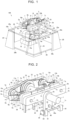
- the repetitive moment generating device 100 will be described on the basis of Figures 1 to 3 .
- the repetitive moment generating device 100 is used for a fatigue testing machine (not illustrated) for testing a fatigue strength property by imparting a repetitive moment on a test piece.
- the repetitive moment generating device 100 includes a principal shaft 1 that is for transmitting a repetitive moment to a test piece (not illustrated) set in the fatigue testing machine, principal bearing members 2a, 2b that are provided to stand on an upper surface of a table 24 at a predetermined distance therebetween to rotatably hold the principal shaft 1, a pair of lever members 3a, 3b that are attached to the principal shaft 1 at positions that are separated from each other in a direction of a shaft center 1c of the principal shaft 1 in a state where each of the lever members 3a, 3b is orthogonal to the principal shaft 1, shaft bodies 4, 5 that are rotatably provided around shaft centers 4c, 5c (see Figure 2 ), each of which is parallel with the principal shaft 1, at positions that are symmetrical with the principal shaft 1 interposed therebetween in a region where the lever members 3a, 3b face each other, eccentric weight rotors 6, 7 that rotate along with the shaft bodies 4, 5 around the shaft centers 4c, 5c, and the like.
- the eccentric weight rotors 6, 7 include diameter expanded portions 6b, 7b provided at parts of the shaft bodies 4, 5, respectively, and eccentric weight members 6c, 7c that are inserted into through-holes 6h, 7h provided to open in the diameter expanded portions 6b, 7b in a direction that is orthogonal to the shaft centers 4c, 5c in a state where the eccentric weight members 6c, 7c are orthogonal to the shaft bodies 4, 5 and in a state where the eccentric weight members 6c, 7c are slidable in a direction that is orthogonal to the shaft bodies 4, 5.
- a motor 14 that is drive means for causing the shaft bodies 4, 5 to synchronously rotate is included.
- the eccentric weight members 6c, 7c include columnar main body portions 6e, 7e and stoppers 6f, 6g, 7f, 7g provided at both end portions of the main body portions 6e, 7e, respectively, in short columnar shapes with diameters expanded as compared with the inner diameters of the through-holes 6h, 7h.
- the main body portions 6e, 7e are slidable in a state where the outer circumferential surfaces thereof are in contact with the inner circumferential surfaces of the through-holes 6h, 7h, and the sliding distances of the eccentric weight members 6c, 7c with respect to the shaft bodies 4, 5 are limited to the lengths of the main body portions 6e, 7e by the stoppers 6f, 6g (7f, 7g), respectively.
- Springs 6d, 7d which are elastic members are disposed in the surroundings of parts located between the stoppers 6f, 7f on one side and the diameter expanded portions 6b, 7b of the shaft bodies 4, 5 in the main body portions 6e, 7e of the eccentric weight members 6c, 7c, and both end portions of the spring 6d (7d) are locked by the diameter expanded portion 6b (7b) and the stopper 6f (7f), respectively.
- the spring 6d (7d) couples the stopper 6f (7f) to the diameter expanded portion 6b (7b) of the shaft body 4 (5) to hold a state where the center of gravity of the eccentric weight member 6c (7c) is located at the shaft center 4c (5c) of the shaft body 4 (5), respectively.
- a slider 30 is attached to an outer circumference of a part of the principal shaft 1 between the lever members 3a, 3b.
- the slider 30 is slidable in the direction of the shaft center 1c of the principal shaft 1, and the principal shaft 1 can idle with respect to the slider 30.
- a slider 31 (32) is attached to an outer circumference of a part of the shaft body 4 (5) between an eccentric rotor 6 (7) and the lever member 3b.
- the slider 31 (32) is slidable in the direction of the shaft center 4c (5c) of the shaft body 4 (5), and the shaft body 4 (5) can idle with respect to the slider 31 (32).
- an interlocking member 33 that integrally couples the sliders 30, 31, 32 is provided to synchronize movement of the sliders 30, 31, 32 in the longitudinal direction of the shaft centers 1c, 4c, 5c.
- the interlocking member 33 is disposed at a part between the eccentric weight rotors 6, 7 and the lever member 3b such that the interlocking member 33 is orthogonal to the principal shaft 1 and the shaft bodies 4, 5 and is parallel with the lever members 3a, 3b.
- a link mechanism 34 (35) is provided as joining means for converting sliding motion occurring when the slider 31 (32) slides in the direction of the shaft center 4c (5c) of the shaft body 4 (5) by causing the interlocking member 33 to move in the direction of the shaft center 1c using operation means, which will be described later, into sliding motion of the eccentric weight member 6c (7c) in a direction that is orthogonal to the shaft center 4c (5c) of the shaft body 4 (5) and transmitting the sliding motion to the eccentric weight member 6c (7c).
- the link mechanism 34 (35) includes a first link member 10 (12) and a second link member 11 (13).
- the first link member 10 (12) is turnably and axially supported by a support shaft 10a (12a) of the slider 31 (32) on one end portion side and is turnably and axially supported by a support shaft 10b (12b) of the stopper 6g (7g) of the eccentric weight member 6c (7c) on the other end portion side.
- the second link member 11 (13) is turnably and axially supported by a support shaft 11a (13a) of the diameter expanded portion 6b (7b) of the shaft body 4 (5) on one end portion side and is turnably and axially supported by a support shaft 11b (13b) at the center portion of the first link member 10 (12) on the other end portion side.
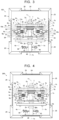
- link mechanisms 34, 35 are illustrated only on the upper surface side of the eccentric weight rotors 6, 7 in Figure 3 , the link mechanisms 34, 35 are also provided on the lower surface side of the eccentric weight rotors 6, 7 illustrated in Figure 2 as partially displayed near the eccentric weight rotor 6 in Figure 2 .
- a pair of link mechanisms 34, 34 (35, 35) are disposed to be mirror symmetrical with the eccentric weight rotor 6 (7) interposed therebetween.
- a male screw member 37 is screwed into a female screw hole 36 provided to open below the slider 30 in a state where the male screw member 37 is parallel with the shaft bodies 4, 5 and the principal shaft 1, and one end portion (not illustrated) of the male screw member 37 is turnably held by a bearing member 43 disposed on the table 24 immediately below the principal shaft 1.
- the other end portion side of the male screw member 37 is turnably inserted into a through-hole 38 provided to open in the principal bearing member 2b, and a helical gear 39 is attached to a distal end of the male screw member 37 projecting from the through-hole 38.
- the male screw member 37 is turnably held by the bearing member 43 and the through-hole 38 of the principal bearing member 2b in a state where movement of the male screw member 37 in the longitudinal direction is constrained.
- the helical gear 39 is attached concentrically with the male screw member 37, a rotation shaft 40 at which the worm gear 40a is formed is disposed below the helical gear 39 such that the rotation shaft 40 multilevel crosses the male screw member 37 at a right angle, and the helical gear 39 is engaged with the worm gear 40a.
- Both end parts of the rotation shaft 40 are turnably held by bearing members 41, 42 disposed on the table 24, respectively, and a handle 44 is attached to the end portion of the rotation shaft 40 projecting from the bearing member 41.
- the rotation shaft 40 and the worm gear 40a rotate, the rotation is transmitted to the helical gear 39, the male screw member 37 rotates with the rotation of the helical gear 39, and the slider 30 with the female screw hole 36 into which the male screw member 37 is screwed and the interlocking member 33 move in the longitudinal direction of the male screw member 37 (the direction of the shaft center 1c of the principal shaft 1).
- the sliders 31, 32 integrated with the interlocking member 33 move in the directions of the shaft centers 4c, 5c of the shaft bodies 4, 5, and the link mechanisms 34, 35 operate.
- the handle 44 is rotated in the direction of the arrow W1 as illustrated in Figure 2 , for example, then the male screw member 37 rotates in the direction of the arrow W2 via the worm gear 40a and the helical gear 39, and the slider 30 and the interlocking member 33 move in a direction separated from the lever member 3b through screwing between the male screw member 37 and the female screw hole 36.
- the sliders 31, 32 integrated with the interlocking member 33 also slide in the direction separated from the lever member 3b, the sliding motion is thus transmitted to the stoppers 6g, 7g of the eccentric weight members 6c, 7c via the link mechanisms 34, 35, the stoppers 6g, 7g move in directions separated from the diameter expanded portions 6b, 7b of the eccentric weight rotors 6, 7, respectively, and the centers of gravity of the eccentric weight members 6c, 7c are separated from the shaft centers 4c, 5c of the shaft bodies 4, 5, respectively.
- the springs 6d, 7d disposed between the stoppers 6f, 7f of the eccentric weight members 6c, 7c on one side and the diameter expanded portions 6b, 7b of the shaft bodies 4, 5 couple the stoppers 6f, 7f to the shaft bodies 4, 5 to hold a state where the centers of gravity of the eccentric weight members 6c, 7c are located at the shaft centers 4c, 5c of the shaft bodies 4, 5.
- the table 24 is a quadrangular flat plate-shaped member and is kept in a horizontal state by four support members 25 disposed on the lower surface side of four corner portions 24c thereof.
- the support members 25 have L-shaped horizontal sections and include bottom plates 25b provided on the lower surface side.
- the four corner portions 24c of the table 24 are fixed in a state where the corner portions 24c are placed on the upper surfaces 25a of the four support members 25, and a quadrangular flat plate-shaped bottom table 26 is disposed on the bottom plates 25b located at the four positions.
- the motor 14, middle timing pulleys 15, 16, a large timing pulley 18, small timing pulleys 19a, 19b, and timing belts 21, 22 are included as drive means for synchronously rotating the two eccentric weight rotors 6, 7. If the motor 14 is activated, then the rotation force thereof is output to a rotation shaft 14a via a gear box 17.
- the middle timing pulley 15 is attached to the rotation shaft 14a that is rotated by the motor 14, and the middle timing pulley 16 and the large timing pulley 18 are rotatably attached to the principal shaft 1 via a bearing.
- the rotation shaft 14a is parallel with the principal shaft 1, and the middle timing pulley 15 on the side of the motor 14 is located immediately below the middle timing pulley 16 on the side of the principal shaft 1 with the middle timing pulleys 15, 16 disposed to face each other in series in the up-down direction.
- the small timing pulleys 19a, 19b are attached to the shaft bodies 4, 5.
- the small timing pulleys 19a, 19b are disposed in series with the large timing pulley 18 interposed therebetween.
- the sizes (outer diameters) of the small timing pulleys 19a, 19b are the same as each other, and the sizes (outer diameters) of the middle timing pulleys 15, 16 are also the same as each other.
- the middle timing pulley 15 and the middle timing pulley 16 are linked with the timing belt 21, and the timing pulleys 19a, 19b and the large timing pulley 18 are linked with the timing belt 22.
- the middle timing pulley 15 attached integrally to the rotation shaft 14a rotates, the rotation of the middle timing pulley 15 is transmitted to the middle timing pulley 16 via the timing belt 21, and the middle timing pulley 16 thus rotates in the same direction as that of the rotation shaft 14a the same number of times of rotation.
- the rotation of the middle timing pulley 16 is transmitted to the large timing pulley 18 integrated with the middle timing pulley 15 via the principal shaft 1.
- the shaft bodies 4, 5 with the small timing pulleys 19a, 19b attached thereto rotate in mutually the same direction the same number of times of rotation. Therefore, the two eccentric weight rotors 6, 7 mutually synchronously rotate in the same direction the same number of times of rotation. Additionally, although the link mechanisms 34, 35 and the sliders 31, 32 also integrally rotate with the rotation of the two eccentric weight rotors 6, 7, the slider 30 and the interlocking member 33 are held in a stationary state. Note that in the repetitive moment generating device 100, the rotation center lines of the two eccentric weight rotors 6, 7 are the same as the shaft centers 4c, 5c of the shaft bodies 4, 5, respectively.
- the two eccentric weight rotors 6, 7 are disposed such that eccentricity directions (the directions of the centrifugal forces 6a, 7a) of the centers of gravity of the eccentric weight members 6c, 7c are different from each other by 180 degrees around the shaft centers 4c, 5c of the shaft bodies 4, 5, respectively. Therefore, the two eccentric weight rotors 6, 7 rotate while maintaining the relationship in which the direction of the centrifugal forces 6a, 7a are different from each other by 180 degrees around the rotation center lines (shaft centers 4c, 5c), respectively.
- the eccentric weight rotors 6, 7 rotate with rotation of the shaft bodies 4, 5 that is rotated by a drive force of the motor 14 as will be described later in a state where the centers of gravity of the eccentric weight members 6c, 7c are eccentric from the shaft centers 4c, 5c, then the eccentric weight members 6c, 7c also rotate about the shaft centers 4c, 5c, and the centrifugal forces 6a, 7a of the magnitudes determined by the amounts of eccentricity of the centers of gravity of the eccentric weight members 6, 7 and the number of times of rotation are generated in the shaft center directions of the main body portions 6e, 7e. Since the directions in which the centrifugal forces 6a, 7a act rotate about the shaft centers 4c, 5c, the directions of the centrifugal forces 6a, 7a change in the up-down and left-right directions with the rotation.
- a torsional moment meter and a rotation angle encoder are used together with the repetitive moment generating device 100, it is also possible to perform closed loop control, to perform testing based not only on torsional moment control but also on angular displacement control and program control, and thereby to include a variety of control functions that are comparable to an advanced hydraulic fatigue testing machine at low cost.
- the repetitive moment generating device 100 illustrated in Figures 1 to 3 includes the two shaft bodies 4, 5, the two eccentric weight rotors 6, 7, the two sliders 31, 32, and the two link mechanisms 34, 35 for the one principal shaft 1, and each component is provided with the amplitude adjustment mechanism
- the present invention is not limited thereto, and it is thus possible to employ a repetitive moment generating device 100 including one shaft body 4 (or 5), one eccentric weight rotor 6 (or 7), one slider 31 (or 32), and one link mechanism 34 (or 35) for the one principal shaft 1 and to obtain the amplitude adjustment function that is similar to that described above in this case as well.
- the repetitive moment generating device 200 is provided with pulleys 50, 51 and wires 52, 53 instead of the link mechanisms 34, 35 illustrated in Figure 3 as the joining means for converting the sliding motion of the sliders 31, 32 in the directions of the shaft centers 4c, 5c of the shaft bodies 4, 5 into the sliding motion of the eccentric weight members 6c, 7c in the direction that intersects the shaft bodies 4, 5 and transmitting the sliding motion to the eccentric weight members 6c, 7c.
- the present invention is not limited to the wires 52, 53, and it is thus also possible to use flexible wire rods, string-like materials, chains, or the like as long as it has a similar function.
- the pulleys 50, 51 are turnably and axially supported by the diameter expanded portions 6b, 7b of the eccentric weight rotors 6, 7, respectively, and the slider 31 (32) and the eccentric weight member 6c (7c) are coupled with the wire 52 (53) via the pulley 50 (51).
- One end portion of the wire 52 (53) is locked by the slider 31 (32), and the other end portion of the wire 52 (53) is locked by the stopper 6f (7f) of the eccentric weight member 6c (7c).
- the repetitive moment generating device 200 can also adjust the amplitude of the repetitive moment imparted on the principal shaft 1 by performing the operation of rotating the handle 44 regardless of whether or not the eccentric weight rotors 6, 7 are rotating. Structures, functions, effects, advantages, and the like of the other parts are similar to those of the repetitive moment generating device 100 described above.
- repetitive moment generating devices 100, 200 described on the basis of Figures 1 to 4 illustrate examples of the repetitive moment generating device according to the present invention, and the repetitive moment generating device according to the present invention is not limited to the aforementioned repetitive moment generating devices 100, 200.
- the repetitive moment generating device according to the present invention can be widely used in a fatigue testing machine or the like for testing a fatigue strength property of a test piece by imparting a repetitive moment on the test piece.
Landscapes
- Physics & Mathematics (AREA)
- General Physics & Mathematics (AREA)
- Health & Medical Sciences (AREA)
- Engineering & Computer Science (AREA)
- Life Sciences & Earth Sciences (AREA)
- Chemical & Material Sciences (AREA)
- Analytical Chemistry (AREA)
- Biochemistry (AREA)
- General Health & Medical Sciences (AREA)
- Mechanical Engineering (AREA)
- Immunology (AREA)
- Pathology (AREA)
- Investigating Strength Of Materials By Application Of Mechanical Stress (AREA)
- Apparatuses For Generation Of Mechanical Vibrations (AREA)
Applications Claiming Priority (2)
| Application Number | Priority Date | Filing Date | Title |
|---|---|---|---|
| JP2020114995A JP7442809B2 (ja) | 2020-07-02 | 2020-07-02 | 繰り返しモーメント発生装置 |
| PCT/JP2021/024768 WO2022004793A1 (fr) | 2020-07-02 | 2021-06-30 | Dispositif de génération de moment répétitif |
Publications (3)
| Publication Number | Publication Date |
|---|---|
| EP4176979A1 true EP4176979A1 (fr) | 2023-05-10 |
| EP4176979A4 EP4176979A4 (fr) | 2023-12-13 |
| EP4176979B1 EP4176979B1 (fr) | 2025-06-25 |
Family
ID=79316308
Family Applications (1)
| Application Number | Title | Priority Date | Filing Date |
|---|---|---|---|
| EP21833039.7A Active EP4176979B1 (fr) | 2020-07-02 | 2021-06-30 | Dispositif de génération de moment répétitif |
Country Status (4)
| Country | Link |
|---|---|
| US (1) | US12292417B2 (fr) |
| EP (1) | EP4176979B1 (fr) |
| JP (1) | JP7442809B2 (fr) |
| WO (1) | WO2022004793A1 (fr) |
Family Cites Families (16)
| Publication number | Priority date | Publication date | Assignee | Title |
|---|---|---|---|---|
| FR1018538A (fr) * | 1949-05-24 | 1953-01-08 | Procédé pour la vibration à fréquences variables de matière finement divisée et appareils vibratoires permettant d'appliquer ce procédé | |
| DE2236695C3 (de) * | 1972-07-26 | 1975-04-17 | Wacker-Werke Kg, 8000 Muenchen | Vorrichtung zur stufenlosen Änderung der Zentrifugalkraft, insbesondere für Vibrations-Erzeuger |
| JPS5248026B2 (fr) * | 1973-12-31 | 1977-12-07 | ||
| DE2742289A1 (de) * | 1977-09-20 | 1979-03-29 | Schlosser & Co Gmbh | Schwingungserreger, insbesondere fuer verdichtungsruettler |
| NZ194594A (en) * | 1979-09-06 | 1984-08-24 | Rexnord Inc | Directionally variable vibration generator |
| US5569858A (en) | 1994-05-16 | 1996-10-29 | The B. F. Goodrich Company | Viscoelastic material testing system |
| US5458002A (en) | 1994-05-16 | 1995-10-17 | The B. F. Goodrich Company | Viscoelastic material testing system |
| JP3183237B2 (ja) | 1997-11-21 | 2001-07-09 | 株式会社ケイ | 可変型振動テーブル用振動装置 |
| US6321610B1 (en) * | 1999-08-08 | 2001-11-27 | Kabushiki Kaisha Kei | Vibration apparatus for a variable amplitude type vibration table |
| CN1676759A (zh) * | 2005-04-27 | 2005-10-05 | 冯忠绪 | 多频合成振动压实方法及压实机用多频合成激振器 |
| JP2007107955A (ja) | 2005-10-12 | 2007-04-26 | Ntn Corp | 捩り疲労試験機 |
| JP5334056B2 (ja) * | 2009-09-15 | 2013-11-06 | 学校法人福岡大学 | 疲労試験機 |
| JP6772679B2 (ja) * | 2016-09-01 | 2020-10-21 | 日本製鉄株式会社 | 疲労試験装置及び疲労試験方法 |
| JP7115201B2 (ja) * | 2018-10-03 | 2022-08-09 | 日本製鉄株式会社 | き裂進展評価方法 |
| CN110631815B (zh) * | 2019-09-26 | 2024-12-10 | 河北宏光供电器材有限公司 | 定位器振动疲劳试验机 |
| WO2021206125A1 (fr) * | 2020-04-08 | 2021-10-14 | 学校法人福岡大学 | Dispositif de génération de moment répété |
-
2020
- 2020-07-02 JP JP2020114995A patent/JP7442809B2/ja active Active
-
2021
- 2021-06-30 WO PCT/JP2021/024768 patent/WO2022004793A1/fr not_active Ceased
- 2021-06-30 EP EP21833039.7A patent/EP4176979B1/fr active Active
-
2022
- 2022-12-23 US US18/088,471 patent/US12292417B2/en active Active
Also Published As
| Publication number | Publication date |
|---|---|
| US20230129401A1 (en) | 2023-04-27 |
| JP2022012863A (ja) | 2022-01-17 |
| EP4176979A4 (fr) | 2023-12-13 |
| US12292417B2 (en) | 2025-05-06 |
| EP4176979B1 (fr) | 2025-06-25 |
| JP7442809B2 (ja) | 2024-03-05 |
| WO2022004793A1 (fr) | 2022-01-06 |
Similar Documents
| Publication | Publication Date | Title |
|---|---|---|
| US9314934B2 (en) | Gravity-counterbalanced robot arm | |
| JP4144021B2 (ja) | 機械的自重補償装置 | |
| WO2009089916A1 (fr) | Manipulateur parallèle à deux degrés de liberté | |
| US9273758B2 (en) | Power transmission device | |
| CN103153556B (zh) | 关节装置的驱动方法 | |
| JP4388566B2 (ja) | 立体カム機構 | |
| Ouyang et al. | Integrated design of robotic mechanisms for force balancing and trajectory tracking | |
| US12292417B2 (en) | Repetitive moment generating device | |
| JP4758119B2 (ja) | 非線形弾性機構及びロボット用関節機構 | |
| US12158451B2 (en) | Repeated moment generation device | |
| JP6799378B2 (ja) | リハビリ装置 | |
| Medina et al. | Design and characterization of a novel mechanism of multiple joint stiffness (MMJS) | |
| JP2009243694A (ja) | 立体カム機構 | |
| Nelson et al. | Variable stiffness mechanism for robotic rehabilitation | |
| Nelson | A novel mechanism for rotational variable stiffness | |
| JP5119394B2 (ja) | 可変減速機 | |
| CN102626922B (zh) | 四支链二维平动一维转动自由度并联机械手 | |
| GB2527064A (en) | A reaction producing device that makes use of gyroscopic rotation to reset a reactive mass | |
| KR100487152B1 (ko) | 다관절 로봇 | |
| CN107351059A (zh) | 一种二自由度解耦的并联机构 | |
| KR20170101549A (ko) | 리스트유닛을 포함하는 로봇 핸드 어셈블리 | |
| KR101981928B1 (ko) | 길이 가변 기구 | |
| Suzuki et al. | Design Principle and Analysis of an Output Cam for a Rotary Actuator Capable of Multidirectional Rapid Motion and Variable Stiffness | |
| Chakarov et al. | Human-oriented robots passive compliance adjustment approach | |
| In et al. | Concept of variable transmission for tendon driven mechanism |
Legal Events
| Date | Code | Title | Description |
|---|---|---|---|
| STAA | Information on the status of an ep patent application or granted ep patent |
Free format text: STATUS: THE INTERNATIONAL PUBLICATION HAS BEEN MADE |
|
| PUAI | Public reference made under article 153(3) epc to a published international application that has entered the european phase |
Free format text: ORIGINAL CODE: 0009012 |
|
| STAA | Information on the status of an ep patent application or granted ep patent |
Free format text: STATUS: REQUEST FOR EXAMINATION WAS MADE |
|
| 17P | Request for examination filed |
Effective date: 20230111 |
|
| AK | Designated contracting states |
Kind code of ref document: A1 Designated state(s): AL AT BE BG CH CY CZ DE DK EE ES FI FR GB GR HR HU IE IS IT LI LT LU LV MC MK MT NL NO PL PT RO RS SE SI SK SM TR |
|
| DAV | Request for validation of the european patent (deleted) | ||
| DAX | Request for extension of the european patent (deleted) | ||
| A4 | Supplementary search report drawn up and despatched |
Effective date: 20231113 |
|
| RIC1 | Information provided on ipc code assigned before grant |
Ipc: G01N 3/32 20060101ALI20231107BHEP Ipc: G01N 3/22 20060101ALI20231107BHEP Ipc: B06B 1/16 20060101ALI20231107BHEP Ipc: B06B 1/12 20060101AFI20231107BHEP |
|
| GRAP | Despatch of communication of intention to grant a patent |
Free format text: ORIGINAL CODE: EPIDOSNIGR1 |
|
| STAA | Information on the status of an ep patent application or granted ep patent |
Free format text: STATUS: GRANT OF PATENT IS INTENDED |
|
| INTG | Intention to grant announced |
Effective date: 20250402 |
|
| GRAS | Grant fee paid |
Free format text: ORIGINAL CODE: EPIDOSNIGR3 |
|
| GRAA | (expected) grant |
Free format text: ORIGINAL CODE: 0009210 |
|
| STAA | Information on the status of an ep patent application or granted ep patent |
Free format text: STATUS: THE PATENT HAS BEEN GRANTED |
|
| AK | Designated contracting states |
Kind code of ref document: B1 Designated state(s): AL AT BE BG CH CY CZ DE DK EE ES FI FR GB GR HR HU IE IS IT LI LT LU LV MC MK MT NL NO PL PT RO RS SE SI SK SM TR |
|
| REG | Reference to a national code |
Ref country code: GB Ref legal event code: FG4D |
|
| REG | Reference to a national code |
Ref country code: CH Ref legal event code: EP |
|
| PGFP | Annual fee paid to national office [announced via postgrant information from national office to epo] |
Ref country code: DE Payment date: 20250606 Year of fee payment: 5 |
|
| REG | Reference to a national code |
Ref country code: CH Ref legal event code: EP |
|
| REG | Reference to a national code |
Ref country code: IE Ref legal event code: FG4D |
|
| REG | Reference to a national code |
Ref country code: DE Ref legal event code: R096 Ref document number: 602021033024 Country of ref document: DE |
|
| PG25 | Lapsed in a contracting state [announced via postgrant information from national office to epo] |
Ref country code: FI Free format text: LAPSE BECAUSE OF FAILURE TO SUBMIT A TRANSLATION OF THE DESCRIPTION OR TO PAY THE FEE WITHIN THE PRESCRIBED TIME-LIMIT Effective date: 20250625 |
|
| REG | Reference to a national code |
Ref country code: LT Ref legal event code: MG9D |
|
| PG25 | Lapsed in a contracting state [announced via postgrant information from national office to epo] |
Ref country code: NO Free format text: LAPSE BECAUSE OF FAILURE TO SUBMIT A TRANSLATION OF THE DESCRIPTION OR TO PAY THE FEE WITHIN THE PRESCRIBED TIME-LIMIT Effective date: 20250925 Ref country code: GR Free format text: LAPSE BECAUSE OF FAILURE TO SUBMIT A TRANSLATION OF THE DESCRIPTION OR TO PAY THE FEE WITHIN THE PRESCRIBED TIME-LIMIT Effective date: 20250926 |
|
| PG25 | Lapsed in a contracting state [announced via postgrant information from national office to epo] |
Ref country code: BG Free format text: LAPSE BECAUSE OF FAILURE TO SUBMIT A TRANSLATION OF THE DESCRIPTION OR TO PAY THE FEE WITHIN THE PRESCRIBED TIME-LIMIT Effective date: 20250625 |
|
| PG25 | Lapsed in a contracting state [announced via postgrant information from national office to epo] |
Ref country code: HR Free format text: LAPSE BECAUSE OF FAILURE TO SUBMIT A TRANSLATION OF THE DESCRIPTION OR TO PAY THE FEE WITHIN THE PRESCRIBED TIME-LIMIT Effective date: 20250625 |
|
| PG25 | Lapsed in a contracting state [announced via postgrant information from national office to epo] |
Ref country code: RS Free format text: LAPSE BECAUSE OF FAILURE TO SUBMIT A TRANSLATION OF THE DESCRIPTION OR TO PAY THE FEE WITHIN THE PRESCRIBED TIME-LIMIT Effective date: 20250925 |
|
| PG25 | Lapsed in a contracting state [announced via postgrant information from national office to epo] |
Ref country code: LV Free format text: LAPSE BECAUSE OF FAILURE TO SUBMIT A TRANSLATION OF THE DESCRIPTION OR TO PAY THE FEE WITHIN THE PRESCRIBED TIME-LIMIT Effective date: 20250625 |
|
| REG | Reference to a national code |
Ref country code: NL Ref legal event code: MP Effective date: 20250625 |
|
| PG25 | Lapsed in a contracting state [announced via postgrant information from national office to epo] |
Ref country code: NL Free format text: LAPSE BECAUSE OF FAILURE TO SUBMIT A TRANSLATION OF THE DESCRIPTION OR TO PAY THE FEE WITHIN THE PRESCRIBED TIME-LIMIT Effective date: 20250625 |
|
| PG25 | Lapsed in a contracting state [announced via postgrant information from national office to epo] |
Ref country code: PT Free format text: LAPSE BECAUSE OF FAILURE TO SUBMIT A TRANSLATION OF THE DESCRIPTION OR TO PAY THE FEE WITHIN THE PRESCRIBED TIME-LIMIT Effective date: 20251027 |
|
| REG | Reference to a national code |
Ref country code: AT Ref legal event code: MK05 Ref document number: 1805953 Country of ref document: AT Kind code of ref document: T Effective date: 20250625 |
|
| PG25 | Lapsed in a contracting state [announced via postgrant information from national office to epo] |
Ref country code: IS Free format text: LAPSE BECAUSE OF FAILURE TO SUBMIT A TRANSLATION OF THE DESCRIPTION OR TO PAY THE FEE WITHIN THE PRESCRIBED TIME-LIMIT Effective date: 20251025 |
|
| PG25 | Lapsed in a contracting state [announced via postgrant information from national office to epo] |
Ref country code: AT Free format text: LAPSE BECAUSE OF FAILURE TO SUBMIT A TRANSLATION OF THE DESCRIPTION OR TO PAY THE FEE WITHIN THE PRESCRIBED TIME-LIMIT Effective date: 20250625 Ref country code: SM Free format text: LAPSE BECAUSE OF FAILURE TO SUBMIT A TRANSLATION OF THE DESCRIPTION OR TO PAY THE FEE WITHIN THE PRESCRIBED TIME-LIMIT Effective date: 20250625 |
|
| PG25 | Lapsed in a contracting state [announced via postgrant information from national office to epo] |
Ref country code: CZ Free format text: LAPSE BECAUSE OF FAILURE TO SUBMIT A TRANSLATION OF THE DESCRIPTION OR TO PAY THE FEE WITHIN THE PRESCRIBED TIME-LIMIT Effective date: 20250625 |
|
| PG25 | Lapsed in a contracting state [announced via postgrant information from national office to epo] |
Ref country code: PL Free format text: LAPSE BECAUSE OF FAILURE TO SUBMIT A TRANSLATION OF THE DESCRIPTION OR TO PAY THE FEE WITHIN THE PRESCRIBED TIME-LIMIT Effective date: 20250625 |
|
| PG25 | Lapsed in a contracting state [announced via postgrant information from national office to epo] |
Ref country code: EE Free format text: LAPSE BECAUSE OF FAILURE TO SUBMIT A TRANSLATION OF THE DESCRIPTION OR TO PAY THE FEE WITHIN THE PRESCRIBED TIME-LIMIT Effective date: 20250625 |
|
| PG25 | Lapsed in a contracting state [announced via postgrant information from national office to epo] |
Ref country code: SK Free format text: LAPSE BECAUSE OF FAILURE TO SUBMIT A TRANSLATION OF THE DESCRIPTION OR TO PAY THE FEE WITHIN THE PRESCRIBED TIME-LIMIT Effective date: 20250625 |
|
| REG | Reference to a national code |
Ref country code: CH Ref legal event code: H13 Free format text: ST27 STATUS EVENT CODE: U-0-0-H10-H13 (AS PROVIDED BY THE NATIONAL OFFICE) Effective date: 20260127 |
|
| PG25 | Lapsed in a contracting state [announced via postgrant information from national office to epo] |
Ref country code: ES Free format text: LAPSE BECAUSE OF FAILURE TO SUBMIT A TRANSLATION OF THE DESCRIPTION OR TO PAY THE FEE WITHIN THE PRESCRIBED TIME-LIMIT Effective date: 20250625 |
|
| PG25 | Lapsed in a contracting state [announced via postgrant information from national office to epo] |
Ref country code: LU Free format text: LAPSE BECAUSE OF NON-PAYMENT OF DUE FEES Effective date: 20250630 |
|
| REG | Reference to a national code |
Ref country code: BE Ref legal event code: MM Effective date: 20250630 |
|
| PG25 | Lapsed in a contracting state [announced via postgrant information from national office to epo] |
Ref country code: RO Free format text: LAPSE BECAUSE OF FAILURE TO SUBMIT A TRANSLATION OF THE DESCRIPTION OR TO PAY THE FEE WITHIN THE PRESCRIBED TIME-LIMIT Effective date: 20250625 |
|
| PG25 | Lapsed in a contracting state [announced via postgrant information from national office to epo] |
Ref country code: MC Free format text: LAPSE BECAUSE OF FAILURE TO SUBMIT A TRANSLATION OF THE DESCRIPTION OR TO PAY THE FEE WITHIN THE PRESCRIBED TIME-LIMIT Effective date: 20250625 |
|
| PG25 | Lapsed in a contracting state [announced via postgrant information from national office to epo] |
Ref country code: IE Free format text: LAPSE BECAUSE OF NON-PAYMENT OF DUE FEES Effective date: 20250630 Ref country code: DK Free format text: LAPSE BECAUSE OF FAILURE TO SUBMIT A TRANSLATION OF THE DESCRIPTION OR TO PAY THE FEE WITHIN THE PRESCRIBED TIME-LIMIT Effective date: 20250625 |
|
| PGFP | Annual fee paid to national office [announced via postgrant information from national office to epo] |
Ref country code: AT Payment date: 20260410 Year of fee payment: 5 |
|
| PG25 | Lapsed in a contracting state [announced via postgrant information from national office to epo] |
Ref country code: IT Free format text: LAPSE BECAUSE OF FAILURE TO SUBMIT A TRANSLATION OF THE DESCRIPTION OR TO PAY THE FEE WITHIN THE PRESCRIBED TIME-LIMIT Effective date: 20250625 Ref country code: BE Free format text: LAPSE BECAUSE OF NON-PAYMENT OF DUE FEES Effective date: 20250630 |
|
| PG25 | Lapsed in a contracting state [announced via postgrant information from national office to epo] |
Ref country code: CH Free format text: LAPSE BECAUSE OF NON-PAYMENT OF DUE FEES Effective date: 20250630 |
|
| PLBE | No opposition filed within time limit |
Free format text: ORIGINAL CODE: 0009261 |
|
| STAA | Information on the status of an ep patent application or granted ep patent |
Free format text: STATUS: NO OPPOSITION FILED WITHIN TIME LIMIT |