EP4177010A1 - Bobinoir préliminaire cylindrique creux pour un outil d'installation d'un insert hélicoïdal en fil métallique - Google Patents
Bobinoir préliminaire cylindrique creux pour un outil d'installation d'un insert hélicoïdal en fil métallique Download PDFInfo
- Publication number
- EP4177010A1 EP4177010A1 EP21206551.0A EP21206551A EP4177010A1 EP 4177010 A1 EP4177010 A1 EP 4177010A1 EP 21206551 A EP21206551 A EP 21206551A EP 4177010 A1 EP4177010 A1 EP 4177010A1
- Authority
- EP
- European Patent Office
- Prior art keywords
- installation
- spindle
- cartridge
- preload
- wire thread
- Prior art date
- Legal status (The legal status is an assumption and is not a legal conclusion. Google has not performed a legal analysis and makes no representation as to the accuracy of the status listed.)
- Granted
Links
Images


Classifications
-
- B—PERFORMING OPERATIONS; TRANSPORTING
- B25—HAND TOOLS; PORTABLE POWER-DRIVEN TOOLS; MANIPULATORS
- B25B—TOOLS OR BENCH DEVICES NOT OTHERWISE PROVIDED FOR, FOR FASTENING, CONNECTING, DISENGAGING, OR HOLDING
- B25B27/00—Hand tools, specially adapted for fitting together or separating parts or objects whether or not involving some deformation, not otherwise provided for
- B25B27/14—Hand tools, specially adapted for fitting together or separating parts or objects whether or not involving some deformation, not otherwise provided for for assembling objects other than by press fit or detaching same
- B25B27/143—Hand tools, specially adapted for fitting together or separating parts or objects whether or not involving some deformation, not otherwise provided for for assembling objects other than by press fit or detaching same for installing wire thread inserts or tubular threaded inserts
-
- B—PERFORMING OPERATIONS; TRANSPORTING
- B23—MACHINE TOOLS; METAL-WORKING NOT OTHERWISE PROVIDED FOR
- B23P—METAL-WORKING NOT OTHERWISE PROVIDED FOR; COMBINED OPERATIONS; UNIVERSAL MACHINE TOOLS
- B23P19/00—Machines for simply fitting together or separating metal parts or objects, or metal and non-metal parts, whether or not involving some deformation; Tools or devices therefor so far as not provided for in other classes
- B23P19/02—Machines for simply fitting together or separating metal parts or objects, or metal and non-metal parts, whether or not involving some deformation; Tools or devices therefor so far as not provided for in other classes for connecting objects by press fit or for detaching same
-
- B—PERFORMING OPERATIONS; TRANSPORTING
- B25—HAND TOOLS; PORTABLE POWER-DRIVEN TOOLS; MANIPULATORS
- B25B—TOOLS OR BENCH DEVICES NOT OTHERWISE PROVIDED FOR, FOR FASTENING, CONNECTING, DISENGAGING, OR HOLDING
- B25B21/00—Portable power-driven screw or nut setting or loosening tools; Attachments for drilling apparatus serving the same purpose
-
- B—PERFORMING OPERATIONS; TRANSPORTING
- B25—HAND TOOLS; PORTABLE POWER-DRIVEN TOOLS; MANIPULATORS
- B25B—TOOLS OR BENCH DEVICES NOT OTHERWISE PROVIDED FOR, FOR FASTENING, CONNECTING, DISENGAGING, OR HOLDING
- B25B29/00—Accessories
- B25B29/02—Bolt tensioners
-
- F—MECHANICAL ENGINEERING; LIGHTING; HEATING; WEAPONS; BLASTING
- F16—ENGINEERING ELEMENTS AND UNITS; GENERAL MEASURES FOR PRODUCING AND MAINTAINING EFFECTIVE FUNCTIONING OF MACHINES OR INSTALLATIONS; THERMAL INSULATION IN GENERAL
- F16B—DEVICES FOR FASTENING OR SECURING CONSTRUCTIONAL ELEMENTS OR MACHINE PARTS TOGETHER, e.g. NAILS, BOLTS, CIRCLIPS, CLAMPS, CLIPS OR WEDGES; JOINTS OR JOINTING
- F16B37/00—Nuts or like thread-engaging members
- F16B37/12—Nuts or like thread-engaging members with thread-engaging surfaces formed by inserted coil-springs, discs, or the like; Independent pieces of wound wire used as nuts; Threaded inserts for holes
- F16B37/122—Threaded inserts, e.g. "rampa bolts"
Definitions
- the present invention relates to a hollow cylindrical preload cartridge of an installation tool of a wire thread insert, which is used in combination with an installation module and a drive module in the installation tool. Furthermore, the present invention relates to a retrofit kit with a plurality of hollow-cylindrical preload cartridges, an installation tool of the above composition, and an installation method for the wire thread insert in a threaded bore of a component with an installation tool.
- wire thread inserts are used in bores with internal threads.
- the wire thread insert consists of a cylindrical wire helix of profiled wire. It is wound with excess relative to the internal thread of the threaded hole to be reinforced.
- An installation tool uses a preload cartridge to wind the wire thread insert onto an installation tool installation mandrel to an outside diameter matching the internal thread.
- a motorized installation tool is in US 2010/0325857 A1 described.
- the installation tool uses a preload cartridge that is spring-loaded in the installation tool. Prior to installation of the wire thread insert, the annular face of the preload cartridge bears against the component adjacent the threaded bore. While the installation spindle turns the wire thread insert into the threaded hole, the preload cartridge plunges into the installation tool against the load of a spring.
- DE 21 43 182 a microswitch downstream of an installing installation spindle.
- the microswitch is triggered as soon as the installation spindle with the wire thread insert has reached a certain depth in the threaded hole.
- the microswitch then triggers a reversal of the direction of rotation of the motor rotating the installation spindle. Accordingly, the installation spindle is unscrewed from the wire thread insert and the wire thread insert is installed in the threaded hole.
- a hollow cylindrical preload cartridge of an installation tool for a wire thread insert according to independent patent claim 1 by an installation tool for a wire thread insert with an installation module with the hollow cylindrical preload cartridge and a motor drive module according to independent patent claim 9, by a retrofit kit for an installation tool for a wire thread insert with a
- a plurality of hollow cylindrical preload cartridges according to claim 13 and solved by an installation method for a wire thread insert in a threaded bore of a component with an installation tool according to claim 14.
- the present invention discloses a hollow-cylindrical preload cartridge of an installation tool for a wire thread insert, which has the following features: a spindle channel running inside the preload cartridge, in which an installation spindle is guided with an installation end and a drive end in an internal spindle guide thread, an outer wall of the preload cartridge at least partially surrounding the spindle channel with a radial positioning window adjacent to a first axial end of the preload cartridge, remote from the drive end of the installation spindle, through which a wire thread insert can be positioned in the spindle channel on the installation spindle, at least one first tactile detection unit, which extends beyond a preferably ring-shaped end face of the preload cartridge at the first axial end protrudes and is displaceable parallel to a longitudinal axis of the preload cartridge, wherein an axial offset of the at least one tactile detection unit can be detected with a first detection sensor of the preload cartridge.
- the prestressing cartridge according to the invention has proven design features, such as a hollow cylindrical shape and a radial positioning window for installing a wire thread insert.
- the use of a spindle guide thread arranged on the radial inside of the hollow-cylindrical preload cartridge is based on these well-known and proven design features.
- the spindle guide thread holds the installation mandrel and translates it longitudinally of the preload cartridge and installation mandrel in response to rotation of the installation mandrel about the longitudinal axis. Since a pitch of the spindle guide thread is preferably known, an axial offset of a wire thread insert to be installed in the installation direction can be derived from the rotation of the installation spindle.
- the installation direction is defined such that it runs parallel to the longitudinal axis of the installation spindle and points into the threaded opening of a component.
- At least one first tactile detection unit protrudes beyond the preferably ring-shaped end face of the preload cartridge at its first axial end.
- the preferably annular face forms the axial end of the preload cartridge which faces the component and the threaded opening or threaded bore selected for the installation of the wire thread insert. It is also preferred to select polygonal or elliptical constructions in addition to an annular end face.
- the at least one tactile detection unit includes a detection sensor with which an axial displacement of the tactile detection unit can be detected. Because the tactile sensing unit protrudes beyond the annular face of the preload cartridge, it preferably makes physical contact with the adjacent surface of the component having the threaded hole.
- the at least one first tactile detection unit detects a distance from the adjacent component surface in qualitative form and/or in absolute form.
- qualitative means that in a preferred control device a distance range between the ring-shaped end face of the preload cartridge and the adjacent component surface, within which a distance detected by the tactile detection unit should lie.
- the at least one tactile detection unit has a sensor pin which is arranged in a spring-loaded manner in a channel of the outer wall.
- the tactile detection unit has a spring-loaded feeler pin in addition to a sensor.
- the feeler pin is preferably guided in a channel in the outer wall of the hollow-cylindrical preload cartridge.
- the spring tension ensures that the spring action pushes the feeler pin in the installation direction of the wire thread insert. This means that the end of the feeler pin protrudes beyond the ring-shaped end face of the preload cartridge and can be pressed against the force of the spring preload through an adjacent component surface into the channel in the wall of the preload cartridge.
- This information can preferably be evaluated in order to detect and evaluate a distance between an adjacent component surface and the ring-shaped end face of the preload cartridge and, based on this information, to give control information to an installation tool during the installation of the wire thread insert.
- the stylus includes an axial sensing end and an axial sensing end, wherein the axial sensing end is positioned adjacent the annular face and the axial sensing end is positioned adjacent the first sensing sensor.
- the stylus includes a sensing end which extends beyond the annular face and a sensing end which moves adjacent the sensing sensor.
- the detection sensor can be of different sensor types, such as an inductive sensor, a capacitive sensor or an optical sensor
- the axial detection end of the feeler pin is adapted according to the sensor principle.
- the sensing end serves to reflect or interrupt certain optical signals from the sensor or the like to produce an optical signal corresponding to the axial position of the stylus.
- the detection end of the Feeler pin the electromagnetic field surrounding the sensor or the perceived capacitance in the sensor, so that due to these changes also a change in the axial position of the feeler pin can be detected.
- This change in axial position of the stylus is preferably produced by contact between the adjacent component surface and the sensing end. Since the feeler pin is spring-loaded in the installation direction, it is also conceivable that the spring action moves the feeler pin in the installation direction without this movement being limited by contact with an adjacent component surface. Thus, the spring bias of the feeler pin would ensure an axial deflection of the feeler pin, which correspondingly generates a signal in the detection sensor.
- its installation spindle has a switching feature adjacent to the drive end, which interacts with a spindle sensor in order to detect an axial offset of the installation spindle in an installation direction of the wire thread insert.
- This axial offset of the wire thread insert only contributes to installation in the threaded bore when the wire thread insert leaves the preload cartridge or passes the ring-shaped end face of the preload cartridge in the installation direction.
- the switching feature is provided adjacent to the drive end of the installation spindle. This switching characteristic is a length-dependent indicator that when it is detected, the installation end of the installation spindle is leaving the preload cartridge.
- Such a switching feature can preferably be implemented by a switching edge or a shoulder in the built-in spindle, which can be detected using an inductive or an optical sensor. If the sensor perceives or detects this switching edge, this is equivalent to the information that the installation end of the installation spindle is leaving the preload cartridge.
- This information is used to determine the further axial offset of the wire thread insert or the installation spindle in the installation direction from this point in time, i.e. from the moment the installation end of the installation spindle leaves the pretensioning cartridge.
- This axial offset allows can preferably be determined by detecting a covered angle of rotation of the installation spindle from this point in time. Multiplying this angle of rotation by the pitch of the inner spindle guide thread results in the axial path of the installation spindle in the installation direction. Since the wire thread insert is held on the installation spindle at the end of the installation spindle, i.e.
- the detected angle of rotation of the installation spindle in combination with the pitch of the inner spindle guide thread represents the path covered by the wire thread insert in the installation direction. Ideally, this information can be used to determine how far the wire thread insert has been screwed into the threaded hole.
- the first detection sensor and preferably a spindle sensor, is an inductive sensor or a capacitive sensor or an optical sensor.
- the movement of the feeler pin of the at least one tactile detection unit and the movement of the installation spindle are detected using sensors.
- the stylus works in conjunction with a detection sensor for this purpose, while the installation mandrel is combined with a mandrel sensor.
- these sensors are formed by inductive or capacitive or optical sensors. It is also conceivable that a combination of these measuring principles is used in order to reliably record the movement of the feeler pin and the installation spindle.
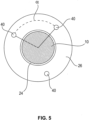
- the hollow-cylindrical preload cartridge has a second tactile detection unit, which protrudes beyond the annular end face of the preload cartridge at the first axial end and can be displaced parallel to a longitudinal axis of the preload cartridge, with an axial offset of the second tactile detection unit using a second detection sensor of the preload cartridge is detectable.
- the first and the second tactile detection unit are preferably spaced apart from one another on the ring-shaped end face by an angle ( ⁇ ) in the range from 10° to 350°.
- the pretensioning cartridge has an internal thread in an axial section between the annular end face and the positioning window for pre-installation of a wire thread insert.
- an internal thread for screwing in the installation spindle with the wire thread insert arranged thereon is provided adjacent to the positioning window of the preload cartridge.
- the wire thread insert is preferably prestressed within this internal thread in such a way that its diameter is reduced for easier screwing into the threaded bore of the component.
- the present invention also discloses an installation tool of a wire thread insert with a motor drive module and a preferred installation module with a preload cartridge according to one of the previously described configurations.
- the preload cartridge is coupled to a motorized drive module.
- the drive module creates a mechanical connection to the installation spindle so that it can be turned with a motor of the drive module and thus moved in the installation direction.
- the motor drive module preferably has a stepper motor or a compressed air motor or a different type of drive for the installation spindle.
- This drive also preferably makes available the detection of the angle of rotation covered and more preferably of the torque transmitted by the installation spindle during the rotation of the installation spindle or the drive module.
- the preload cartridge is preferably arranged in an installation module in the installation tool.
- the installation module or the pretensioning cartridge can be releasably connected to the drive module.
- the pretensioning cartridge can be releasably connected to the drive module.
- the installation tool is preferably alternatively connected to an installation machine, preferably robot-guided, or provided as a hand-held device.
- the installation tool is used in combination with an automatic installation device or as a hand-held device.
- the different application alternatives have an influence on the equipment of the preferred preload cartridge the number of tactile detection units. Because in a preferred built-in machine, the installation tool is fixed in its orientation to the threaded hole. Therefore, due to this arrangement, tilting of the installation tool in relation to the longitudinal axis of the threaded hole is largely ruled out. In this case, it is preferably sufficient if the preload cartridge is equipped with only one tactile detection unit.
- the installation tool is used as a hand-held device, this can rather lead to a non-coaxial alignment of the longitudinal axis of the installation spindle with a longitudinal axis of the threaded hole.
- the pretensioning cartridge has at least two tactile detection units in order to avoid any angular alignment between the longitudinal axis of the installation tool and the longitudinal axis of the threaded hole.
- the installation tool has a control device with which data from at least one detection sensor of the installation tool can be received and evaluated.
- the data recorded by the sensors used are preferably collected and evaluated with the aid of the control unit of the installation tool that is preferred according to the invention.
- These sensors preferably include at least one detection sensor of the at least one tactile detection unit and the spindle sensor for monitoring the axial movement of the installation spindle of the installation tool.
- the control unit receives data from the motorized drive module about the angle of rotation covered by the drive and thus the installation spindle.
- the motorized drive module transmits information about the torque transmitted by the installation spindle to the wire thread insert to the control unit.
- the torque applied by the installation spindle gives an indication of whether the wire thread insert could be screwed into the internal thread of the threaded hole without any problems or whether installation errors occurred during this screwing or installation of the wire thread insert in the threaded hole. This is because such installation errors lead to an increase in torque as the wire thread insert leaves the specified internal thread of the threaded opening during installation. In the same way, the detection of an undertorque serves to interpret the result of the installation process. A torque below a specified threshold indicates that the wire thread insert on the installation spindle has not been screwed into the threaded hole at all.
- the present invention also discloses a retrofit kit for a wire thread insert installation tool having a releasably connectable drive module and a preload cartridge adapted to a wire thread insert comprising at least two preload cartridges according to any of the previously described embodiments of the present invention, which differ in a construction and/or dimension of the installation mandrel or the preload cartridge.
- Common installation tools are also composed of a motorized drive module and a preload cartridge.
- a retrofit kit with a plurality of preload cartridges according to the various preferred embodiments of the present invention is provided. These preload cartridges, which can each be releasably connected to the existing drive module, can be coupled to the existing motorized drive modules in order to implement the functionality of the present invention.
- a retrofit kit preferably comprises at least two preload cartridges according to the various preferred configurations of the present invention.
- the motor drive module does not already have a control device for evaluating sensor data, it is also preferred to equip the known motor drive module with an additional control device according to the above properties.
- the present invention also discloses an installation method for a wire thread insert in a threaded bore of a component with an installation tool, in particular an installation tool according to one of the above embodiments, which has the following steps: pre-installing a wire thread insert on an installation spindle in a preload cartridge of the installation tool, arranging the installation tool with the pre-installed wire thread insert adjacent to an entrance of a threaded bore in an approximately coaxial orientation of the installation mandrel to a longitudinal axis of the threaded bore, axially moving the wire thread insert with the installation mandrel in an installation direction into the threaded bore by rotating the installation mandrel, in particular by guiding the rotating installation mandrel in an inner one Spindle guide thread of a preload cartridge, detecting during the rotation of the installation spindle a covered angle of rotation of the installation spindle, from which an installation depth of a wire thread insert in the threaded opening can be estimated by multiplying by a pitch of a spindle thread of the installation spin
- the inventive installation method for a wire thread insert builds on known installation procedures. Even with the installation method preferred according to the invention, the wire thread insert in the prestressing cartridge is first pretensioned on the installation spindle and then the screwing of the wire thread insert into the threaded hole is started. In order to be able to reliably evaluate the installation process of the wire thread insert, the angle of rotation covered by the installation spindle is recorded after the wire thread insert leaves the pretensioning cartridge in the axial installation direction. The angle of rotation covered gives indirect information about the path covered by the wire thread insert in the axial installation direction. This means that when the wire thread insert immediately enters the threaded hole, the angle of rotation of the installation spindle covered by the rotation of the installation spindle represents the installation depth of the wire thread insert. In this way, it is possible to specify a desired installation depth in advance of an installation process, at which the wire thread insert should preferably be at least installed.
- the size of a distance between the annular Front side of the preload cartridge queried adjacent to the adjacent component and the adjacent component surface of the adjacent component is preferably be within a predefined tolerance range or must not exceed a predefined limit value in order to ensure that the wire thread insert has been screwed sufficiently deep into the threaded hole of the component based on the angle of rotation covered by the installation spindle.
- This distance is detected using a tactile detection unit which, with a preferred feeler pin, protrudes beyond the ring-shaped end face of the preload cartridge in the direction of the component in the installation direction. Since this preferred sensor pin is spring-loaded in the installation direction, contact between the sensor pin and the component surface ensures a detectable deflection of the sensor pin in or against the installation direction. In this way it is possible that the distance between the ring-shaped end face of the preload cartridge and the opposite component surface can be detected.
- the installation method according to the invention of the wire thread insert ends with the fact that, after a rotation angle of the installation spindle has been covered, a preferred control unit or a preferred control device is used to query whether the distance between the annular end face of the prestressing cartridge and the opposite component surface is within a predetermined distance range or below a predetermined one absolute distance to complete an installation process of the wire thread insert as ok.
- this has the additional step: evaluating the detected distance of the at least one tactile detection unit to determine whether it is within or outside of a predefined distance range.
- the following additional method step is also preferably used: determining an absolute distance by querying the at least one tactile detection unit and evaluating whether the absolute distance is within or outside a predefined distance range.
- the distance between the annular end face of the preload cartridge and the opposite component surface is detected qualitatively or quantitatively in order to evaluate on this basis whether the installation of the wire thread insert in the threaded hole is correct or not.
- the tactile detection unit detects the exact distance or the exact distance between the face of the preload cartridge and the opposite component surface.
- This can preferably be technically implemented with a spring-loaded feeler pin in combination with a detection sensor. This procedure forms the basis for when a maximum distance is stored in a connected preferred control device and this must not be exceeded. In this case, a comparison would be made within the control unit between the stored maximum distance and the measured absolute distance.
- the tactile detection unit In combination with the control unit, outputs the information as to whether or not a distance is within a permissible distance range. Accordingly, the information would then be provided as to whether the installation process of the wire thread insert is in order or not.
- torque of the installation mandrel be sensed during rotation of the installation mandrel as the Wire Thread Insert is moved axially into the threaded opening.
- a torque used by the installation spindle is evaluated during the installation of the wire thread insert. It is not primarily about the absolute determination of what is used torque during installation. Rather, this evaluation should be used to qualitatively determine whether the wire thread insert was reliably installed in the threaded hole of the component. This is because it is possible that the wire thread insert will not engage the internal thread of the tapped hole when the installation process starts and will therefore not be installed. This can be seen from the fact that the torque applied by the installation spindle is too small to actually represent screwing the wire thread insert into the internal thread of the threaded hole.
- a detected torque of the installation spindle exceeds a predefined threshold value, this would indicate that an error or a problem has occurred when screwing the wire thread insert into the internal thread of the component opening. This could be the case, for example, if the wire thread insert has jammed in the threaded hole while it is being screwed in. In this case, too, the installation process would not be correct and would have to be repeated after preferentially removing the wire thread insert from the threaded hole.
- the movement of the installation spindle in the installation direction is preferably interrupted in a further step of the installation method if a first predetermined torque is exceeded and/or if a second predetermined torque is not reached.
- At least one of the following variables is shown on a display: the torque of the installation spindle, the angle of rotation covered by the installation spindle and a distance detected by the at least one tactile detection unit.
- this is used in combination with an installation machine or in combination with a hand-held device for installing a wire thread insert in a threaded hole in a component.
- the built-in machine preferably automatically evaluates the data from the sensors used and also automatically interprets this data, it is not absolutely necessary for this data to be displayed, for example on a display.
- the installation method is used in combination with a hand-held device by a worker
- relevant sensor data for interpretation, information and/or evaluation by the worker are preferably shown on a display.
- This display preferably shows qualitative data. This means that an OK or NOK symbol is used to signal whether a distance and/or a torque is OK or not OK during the installation and/or the entire installation process.
- the worker is given absolute values for the distance between the component surface and the ring-shaped end face of the preload cartridge and/or for the rotation angle covered or the axial offset during and/or after installation of the installation spindle and/or for the torque applied by the installation spindle during installation on the display.
- This display gives the worker the opportunity to assess whether the installation of the wire thread insert was successful or not based on known values to be achieved for distance, torque and installation depth.
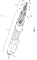
- FIG 1 a preferred embodiment of an installation tool 1 is shown.
- a wire thread insert D is installed in a female threaded hole G of a component B.
- Such installation tools consist of a motor-driven drive module A and an installation module M with a preload cartridge 20.
- the motor-driven drive module A provides a rotational movement for the installation module M, which is generated according to different preferred embodiments of the present invention with an electric motor or a pneumatic motor.
- the drive module A and the installation module M with the preload cartridge 20 are also preferably connected to one another in a detachable or fixed manner.
- a drive module A and installation module M that are detachably connected to one another have the advantage that installation modules M whose dimensions are adapted to different sizes of wire thread inserts D can be interchangeably connected to the drive module A.
- these installation tools 1 are adapted to install different designs of wire thread inserts D.
- These wire thread inserts D have, for example, a removable installation spigot, an installation notch, or a bend-back installation spigot.
- the installation tool 1 of the present invention is suitable for installing these various wire thread inserts.
- the installation module M with the preload cartridge is detachably connected to the drive module A via a mechanical coupling K.
- This connection between drive module A and installation module M establishes a connection between a motor of drive module A and an installation spindle 10 of preload cartridge M. This transmits rotation of the motor to the installation mandrel 10 to install the wire thread insert D or to remove the installation mandrel 10 from the threaded hole G.
- the installation module includes electrical lines and/or connections in order to connect a preferred sensor of the preload cartridge and/or communication lines of the preload cartridge to a control unit of the installation tool.
- the installation mandrel 10 has a drive end 12 for connection to the motor or drive module A .
- An installation thread 16 is provided at an installation end 14 of the installation spindle 10, onto which a wire thread insert D to be installed can be screwed on.
- the installation mandrel 10 is adapted to engage a wire threaded insert D .
- the installation spindle 10 of figure 3 a radial end-side projection 18 to a mounting pin (not shown) to keep a wire thread insert D when screwing into the threaded bore G non-rotatably.
- the installation spindle 10 is arranged in the preload cartridge 20 .
- the basic structure and function of the preload cartridge 20 are known in the prior art.
- the preload cartridge 20 is constructed as a hollow cylinder and has a peripheral wall 22.
- a spindle channel 24 is provided within the hollow cylindrical preload cartridge 20, in which the installation spindle 10 runs.
- the spindle channel 24 is preferably arranged coaxially to a central longitudinal axis of the preload cartridge 20 .
- a spindle guide thread 25 is provided inside the spindle channel 24 on the radial inner wall.
- the spindle guide thread 25 is designed to match the thread 16 of the installation spindle 10 .
- an axial offset of the mounting spindle 10 can be calculated from an angle of rotation covered by the installation spindle 10 and a pitch of the spindle guide thread 25 and/or the thread 16 . To do this, the pitch and the rotation of the installation spindle 10 are multiplied.
- the length of the installation spindle 10 is matched to the preload cartridge 20 . If the installation end 14 of the installation spindle 10 leaves the prestressing ring 30 in the installation direction R E , a switching feature 13 of the installation spindle 10 moves past a spindle sensor 60 at the same time.
- the spindle sensor 60 is preferably designed as an inductive or optical or capacitive sensor.
- the switching feature 13 is preferably a switching edge in the construction of the built-in spindle 10 or an inductively or capacitively or optically detectable feature.
- the spindle sensor 60 preferably detects the switching feature 13 from the radial outside or the radial inside of the preload cartridge 20. It is also preferred to arrange the spindle sensor 60 in the wall 22 of the preload cartridge 20.
- the spindle sensor 60 is connected or can be connected to a control device S of the installation tool 1 .
- the preload cartridge 20 is provided as a retrofit kit (see below), it is preferred that preload cartridges 20 of different installation spindle constructions and/or dimensions can each be connected to the control unit S of the drive module A or the installation tool 1 .
- Control unit S receives the data from spindle sensor 60 and preferably from other sensors, such as at least one detection sensor 50 of at least one tactile detection unit 40.
- data from drive module A is preferably transmitted to control unit S.
- This preferably includes a torque to be applied by a motor of the drive module A in order to rotate the installation spindle 10 and install a wire thread insert.
- Drive module A also preferably detects an angle of rotation covered by installation spindle 10 and transmits this data to control unit S.
- the axial offset of installation end 14 of installation spindle 10 is determined from an angle of rotation covered by installation spindle 10, preferably by multiplying it by the pitch of spindle guide thread 25.
- annular mounting end face or generally end face 26 is provided at an axial end 21 of the pretensioning cartridge 20 facing away from the drive module A.
- the mounting face 26 is preferably arranged in a radial plane perpendicular to the longitudinal axis of the installation spindle 10 .
- the annular face 26 does not necessarily land on the adjacent surface OB of the component B during the installation of a wire thread insert D described below.
- the preload cartridge 20 Adjacent to the axial end 21 the preload cartridge 20 has a radial positioning window 28 .
- a wire thread insert D is placed in the bias cartridge 20 through the radial locating window 28 as is well known. The wire thread insert D is then screwed onto the thread 16 of the installation spindle 10 in order to then be screwed into a preload ring 30 with an internal thread 32 of the preload cartridge 20 and preloaded in it. The wire thread insert D is later screwed into the internal thread of the threaded bore G from the preload ring 30 .
- the annular mounting face 26 runs concentrically around the central longitudinal axis of the installation spindle 10. According to a preferred embodiment of the present invention, it lies in a radial plane perpendicular to the central longitudinal axis of the installation spindle 10.
- the installation tool 1 is arranged adjacent to the threaded bore G of a component B.
- the installation tool 1, in particular the central longitudinal axis of the installation spindle 10, is preferably aligned approximately coaxially with the central longitudinal axis of the threaded hole G (see Fig Figures 6 cd ).
- the threaded bore G runs perpendicularly to the component surface O B which adjoins the seating face 26 or is arranged adjacent thereto. Accordingly, it is preferred according to the invention if the installation tool 1 is also arranged approximately perpendicularly to the adjacent component surface O B .
- the preload cartridge 20 preferably comprises the at least one tactile detection unit 40, preferably consisting of a feeler pin 42 and a detection sensor 50.
- the feeler pin 42 is guided in a guide or channel 46 in the wall 22 of the preload cartridge 20.
- a contact end 54 of the feeler pin 42 is preferably spring-loaded in the installation direction R E and protrudes beyond the annular end face 26 . If the contact end 54 comes into contact with an adjacent component surface O B , the feeler pin 42 is deflected counter to the installation direction R E against a force of a preferred spring. The deflection of feeler pin 42 is detected by the at least one detection sensor 50 and preferably transmits the data to control unit S.
- the contact end 54 of the feeler pin 42 is supported on the adjacent component surface O B .
- the associated axial deflection of the feeler pin 42 is detected by the detection sensor 50 and transmitted to the control unit S.
- the data transmitted from the detection sensor 50 to the control unit S describe the distance between the annular end face 26 of the preload cartridge 20 and the component surface O B of the component B with the threaded hole G.
- the distance is preferably determined absolutely with the detection sensor 50 . According to a further preferred embodiment of the present invention, it is determined whether or not the detected distance exceeds a maximum distance. This therefore corresponds to a qualitative determination of the distance, which preferably does not require the specification of an exact distance value.
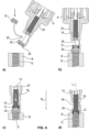
- the preferred installation method of the wire thread insert D according to the invention is described with reference to the flow chart of FIG figure 8 as well as the representations of figures 6 and 7 explained in more detail.
- the installation procedure is preferably performed by the preload cartridge 20 described above in its preferred embodiments in combination with the drive module A.
- the installation method is performed using a handheld device.
- the installation method is carried out using an installation machine and the pretensioning cartridge 20 with drive module A.
- the installation spindle 10 is retracted by turning it counter to the installation direction R E in a step ST 0 .
- the internal thread 32 of the prestressing ring 30 and the adjoining spindle channel 24 for inserting the wire thread insert D are freely accessible through the radial positioning window 28 .
- the wire thread inserts D is then positioned in the installation direction R E over the preload ring 30, as shown in FIGS Figures 6a , b is shown (ST 1).
- the annular end face 26 is arranged adjacent to the threaded bore G and in particular the preload cartridge 20, preferably coaxially with the longitudinal axis of the threaded bore G.
- the distance between the end face 26 and the component surface OB is queried using the at least one tactile detection unit 40 (ST 2).
- the installation process can be continued. This is done automatically when using a built-in machine.
- the worker is preferably informed via a display or an acoustic signal or an optical signal that the arrangement of the preload cartridge 20 and component B does not meet the requirements or just meets the requirements.
- This signal preferably constitutes a prompt for the worker to rearrange the installation tool and continue the installation process if the required clearance does not meet requirements. If the worker is informed that the distance measurement is correct, he continues the installation process. It is also preferred to signal the worker only when the installation needs to be stopped.
- the installation spindle 10 is rotated in step ST 3 so that it moves in the direction Preload ring 30 is moved, is screwed into the wire thread insert D and the wire thread insert D is screwed into the internal thread 32 of the preload ring 30 or preloads there (see Figures 6b, c ).
- step ST 3 the torque transmitted by the motor of the drive module A to the installation spindle 10 is preferably compared with a predetermined maximum torque. If a predetermined maximum torque is exceeded, this indicates a defect in preinstalling the wire thread insert D in the preload ring 30 .
- the comparison between the current torque of the installation spindle 10 and a maximum torque is preferably carried out in the control unit S. This comparison takes place alternatively in real time during the pre-installation or after the completion of the pre-installation.
- the installation machine preferably turns the installation spindle 10 back again and moves it counter to the installation direction R E .
- the worker is informed acoustically, optically or via a display of the detected defect or the detected exceeding of the maximum torque. Accordingly, the worker then moves the installation spindle 10 back in order to identify the cause of the defect and to remedy the defect.
- step ST 4 After the wire thread insert D is pre-installed in the preload cartridge 20, the installation or screwing of the wire thread insert D into the threaded opening G of the component B takes place in step ST 4 (see Figures 7a, b ).
- the worker starts the rotation of the installation spindle 10 manually on the hand-held device and the installation machine automatically starts the rotation of the installation spindle 10.
- This causes the installation spindle 10 and thus the installation end 14 with the wire thread insert D to move in the installation direction RE to the component B and into the threaded hole G.
- the installation spindle 10 moves in
- the switching feature 13 moves past the spindle sensor 60 at the same time and starts recording the angle of rotation covered by the installation spindle 10 from this point in time ( ST 5).
- the angle of rotation covered by the installation spindle 10 is used to calculate how far the installation end 14 has moved in the installation direction R E .
- This constructive arrangement also opens up the preferred embodiment of the installation method, in that the control unit S specifies a maximum installation path for the installation spindle 10 in the installation direction R E , beginning at the end face 26 of the preload cartridge 20 .
- the maximum installation path is preferably determined by a predefined angle of rotation that is stored in the control unit S. The angle of rotation is detected as soon as the switching feature 13, preferably a switching edge of the built-in spindle 10, the spindle sensor 60 passes. As soon as the angle of rotation covered by the installation spindle 10 has reached the predefined value, the rotation of the installation spindle 10 is stopped (ST 7). On In this way, a desired maximum installation depth of the wire thread insert D in the threaded bore G is preferably specified.
- the torque used by the installation spindle 10 is also preferably recorded and evaluated (ST 6). If the torque exceeds a predetermined threshold, this indicates an error in the installation. Accordingly, the installation process is stopped and the installation spindle 10 is removed from the threaded hole G. This is done automatically by the installation machine or manually by the worker by turning back the installation spindle 10.
- the distance between the annular end face 26 and the adjacent component surface OB is evaluated by the control unit S (ST 8).
- the data for assessing the distance is preferably supplied by the at least one tactile detection unit 40 with the feeler pin 42 to the control unit S, whose contact end 54 preferably acts on the component surface OB .
- the control unit S compares the distance data supplied with a predefined maximum distance or a maximum distance stored in the control unit S. If the maximum distance is exceeded, the installation of the wire thread insert D is not correct. Accordingly, the installation spindle 10 is turned back and the installation process is qualified as not completed or as not in order.
- the installation is concluded as OK.
- the installation mandrel 10 is then removed from the wire thread insert D.
- the wire thread insert D is screwed into the threaded hole G below the component surface O B .
- the threaded hole G is strengthened better than if the wire thread insert D were to abut the component surface O B after installation. Therefore, an angle of rotation for installation and thus a movement of the installation spindle 10 in the installation direction R E is preferably specified over a distance that multiplies the axial length of the wire thread insert D by a certain minimum amount, preferably the pitch of the spindle guide thread by an angle of 450°, for example. exceeds.
- the minimum amount is preferably chosen according to the application.
- the above selected preferred installation distance of the length of the wire thread insert D plus 450° angle of rotation of the installation spindle 10 multiplied by the pitch of the thread of the installation spindle 10 ensures that the wire thread insert D is installed below the component surface OB .
- This delayed entry of the wire thread insert D into the internal thread of the threaded opening G by a specific angle of rotation has the result that, at the end of the installation of the wire thread insert D, the annular end face 26 of the preload cartridge 20 is arranged at a distance from the component surface O B .
- This distance corresponds approximately to the product of the angle of rotation offset and the pitch of the spindle guide thread or the spindle thread 16 or the wire thread insert D, since these are preferably the same.
- an installation of the wire thread insert D is also classified as correct if the ring-shaped end face 26 is arranged by the distance according to the product of the angle of rotation offset, preferably a maximum of 360°, and the pitch of the thread 16 of the installation spindle 10 to the component surface.
Landscapes
- Engineering & Computer Science (AREA)
- Mechanical Engineering (AREA)
- General Engineering & Computer Science (AREA)
- Automatic Assembly (AREA)
- Hand Tools For Fitting Together And Separating, Or Other Hand Tools (AREA)
Priority Applications (7)
| Application Number | Priority Date | Filing Date | Title |
|---|---|---|---|
| HUE21206551A HUE066024T2 (hu) | 2021-11-04 | 2021-11-04 | Egy huzalmenet betét szerelõszerszámjának üreges-hengeres elõfeszítõ patronja |
| EP21206551.0A EP4177010B8 (fr) | 2021-11-04 | 2021-11-04 | Bobinoir préliminaire cylindrique creux pour un outil d'installation d'un insert hélicoïdal en fil métallique |
| ES21206551T ES2976650T3 (es) | 2021-11-04 | 2021-11-04 | Boquilla de guía cilíndrica hueca para una herramienta de instalación de un inserto roscado de alambre |
| JP2022173180A JP7574258B2 (ja) | 2021-11-04 | 2022-10-28 | ワイヤねじインサートの取付け工具用の中空円筒形プリロードカートリッジ、取付け工具、取付け工具用の中空円筒形プリロードカートリッジを用いる改造キット及びワイヤねじインサートの取付け方法 |
| CN202211357935.6A CN116061132B (zh) | 2021-11-04 | 2022-11-01 | 预载筒、安装工具、改装套件及钢丝螺套的安装方法 |
| US17/979,368 US11724374B2 (en) | 2021-11-04 | 2022-11-02 | Hollow-cylindrical preloading cartridge for an installation tool of a wire thread insert, the installation tool, a retrofit kit with hollow-cylindrical preloading cartridges for it as well as an installation method for the wire thread insert |
| KR1020220145065A KR102585013B1 (ko) | 2021-11-04 | 2022-11-03 | 와이어 스레드 인서트의 설치 도구를 위한 중공-원통형 프리로딩 카트리지, 설치 도구, 이를 위한 중공-원통형 프리로딩 카트리지를 갖는 개장 키트, 및 와이어 스레드 인서트를 위한 설치 방법 |
Applications Claiming Priority (1)
| Application Number | Priority Date | Filing Date | Title |
|---|---|---|---|
| EP21206551.0A EP4177010B8 (fr) | 2021-11-04 | 2021-11-04 | Bobinoir préliminaire cylindrique creux pour un outil d'installation d'un insert hélicoïdal en fil métallique |
Publications (4)
| Publication Number | Publication Date |
|---|---|
| EP4177010A1 true EP4177010A1 (fr) | 2023-05-10 |
| EP4177010B1 EP4177010B1 (fr) | 2024-02-14 |
| EP4177010C0 EP4177010C0 (fr) | 2024-02-14 |
| EP4177010B8 EP4177010B8 (fr) | 2024-03-20 |
Family
ID=78528764
Family Applications (1)
| Application Number | Title | Priority Date | Filing Date |
|---|---|---|---|
| EP21206551.0A Active EP4177010B8 (fr) | 2021-11-04 | 2021-11-04 | Bobinoir préliminaire cylindrique creux pour un outil d'installation d'un insert hélicoïdal en fil métallique |
Country Status (7)
| Country | Link |
|---|---|
| US (1) | US11724374B2 (fr) |
| EP (1) | EP4177010B8 (fr) |
| JP (1) | JP7574258B2 (fr) |
| KR (1) | KR102585013B1 (fr) |
| CN (1) | CN116061132B (fr) |
| ES (1) | ES2976650T3 (fr) |
| HU (1) | HUE066024T2 (fr) |
Families Citing this family (1)
| Publication number | Priority date | Publication date | Assignee | Title |
|---|---|---|---|---|
| CN116587223B (zh) * | 2023-06-25 | 2026-01-23 | 沈阳航空航天大学 | 一种适配于自动化设备的双头螺柱安装工具 |
Citations (4)
| Publication number | Priority date | Publication date | Assignee | Title |
|---|---|---|---|---|
| DE2143182A1 (de) | 1970-10-22 | 1972-04-27 | Groov-Pin Corp., Ridgefield, N.J. (V.StA.) | Eindrehwerkzeug für Gewindebüchsen |
| US4553302A (en) | 1984-02-21 | 1985-11-19 | Rexnord Inc. | Installation tool, tangless helically coiled insert |
| EP1084800A2 (fr) * | 1999-09-15 | 2001-03-21 | Drummond Plaza Office Park | Outil motorisé pour filet hélicoidal |
| US20100325857A1 (en) | 2009-06-25 | 2010-12-30 | Newfrey, Llc | Retractable Prewinder Assembly With Infinite Adjustability For Installation Of Helically Coiled Wire Inserts |
Family Cites Families (7)
| Publication number | Priority date | Publication date | Assignee | Title |
|---|---|---|---|---|
| US4172314A (en) * | 1977-05-23 | 1979-10-30 | Microdot Inc. | Tool for installing thread insert |
| KR20020057309A (ko) * | 2001-01-04 | 2002-07-11 | 송재인 | 헬리코일의 인서트 제어기 |
| US6860173B2 (en) * | 2002-12-13 | 2005-03-01 | Newfrey Llc | Power installation tool for helical coil inserts |
| JP2006095626A (ja) | 2004-09-29 | 2006-04-13 | Honda Motor Co Ltd | 自動工具 |
| US7634844B2 (en) | 2006-04-19 | 2009-12-22 | Newfrey Llc | Adjustable prewinder assembly for wire insert installation tool |
| JP4535058B2 (ja) | 2006-11-13 | 2010-09-01 | パナソニック電工株式会社 | 回転式工具 |
| TWI542452B (zh) | 2010-07-30 | 2016-07-21 | 日本史普魯股份有限公司 | 用於無尾螺旋線圈護套的插入工具 |
-
2021
- 2021-11-04 HU HUE21206551A patent/HUE066024T2/hu unknown
- 2021-11-04 ES ES21206551T patent/ES2976650T3/es active Active
- 2021-11-04 EP EP21206551.0A patent/EP4177010B8/fr active Active
-
2022
- 2022-10-28 JP JP2022173180A patent/JP7574258B2/ja active Active
- 2022-11-01 CN CN202211357935.6A patent/CN116061132B/zh active Active
- 2022-11-02 US US17/979,368 patent/US11724374B2/en active Active
- 2022-11-03 KR KR1020220145065A patent/KR102585013B1/ko active Active
Patent Citations (4)
| Publication number | Priority date | Publication date | Assignee | Title |
|---|---|---|---|---|
| DE2143182A1 (de) | 1970-10-22 | 1972-04-27 | Groov-Pin Corp., Ridgefield, N.J. (V.StA.) | Eindrehwerkzeug für Gewindebüchsen |
| US4553302A (en) | 1984-02-21 | 1985-11-19 | Rexnord Inc. | Installation tool, tangless helically coiled insert |
| EP1084800A2 (fr) * | 1999-09-15 | 2001-03-21 | Drummond Plaza Office Park | Outil motorisé pour filet hélicoidal |
| US20100325857A1 (en) | 2009-06-25 | 2010-12-30 | Newfrey, Llc | Retractable Prewinder Assembly With Infinite Adjustability For Installation Of Helically Coiled Wire Inserts |
Also Published As
| Publication number | Publication date |
|---|---|
| US11724374B2 (en) | 2023-08-15 |
| EP4177010B1 (fr) | 2024-02-14 |
| KR20230065180A (ko) | 2023-05-11 |
| EP4177010B8 (fr) | 2024-03-20 |
| US20230139341A1 (en) | 2023-05-04 |
| ES2976650T3 (es) | 2024-08-06 |
| HUE066024T2 (hu) | 2024-07-28 |
| EP4177010C0 (fr) | 2024-02-14 |
| JP2023070111A (ja) | 2023-05-18 |
| KR102585013B1 (ko) | 2023-10-04 |
| CN116061132A (zh) | 2023-05-05 |
| CN116061132B (zh) | 2024-03-15 |
| JP7574258B2 (ja) | 2024-10-28 |
Similar Documents
| Publication | Publication Date | Title |
|---|---|---|
| DE69800354T2 (de) | Verfahren zur Formung einer Stanznietverbindung | |
| EP0860220A2 (fr) | Presse | |
| DE2825022A1 (de) | Motorgetriebene werkzeugmaschine in form einer kombination aus bohrmaschine und schraubenzieher | |
| EP1564522A2 (fr) | Micromètre | |
| EP0715708B1 (fr) | Outil a presser | |
| EP3134670A1 (fr) | Module connecteur | |
| AT517104B1 (de) | Messvorrichtung und Messverfahren zum Messen der Geometrie eines hohlzylindrischen Objektes | |
| DE102009054923A1 (de) | Handwerkzeugmaschine | |
| DE102010017739B4 (de) | Gewindepanzerndes Element, Schraube mit gewindepanzerndem Element, Installationsverfahren dafür, ein Bauteil mit installiertem gewindepanzernden Element, Wickelspindel zum Herstellen eines gewindepanzernden Elements sowie Herstellungsverfahren eines gewindepanzernden Elements | |
| EP1469958A1 (fr) | Outil de pose equipe de systemes de controle de processus de pose | |
| EP4177010B1 (fr) | Bobinoir préliminaire cylindrique creux pour un outil d'installation d'un insert hélicoïdal en fil métallique | |
| DE102010001503B4 (de) | Spindelantrieb einer Verstelleinrichtung eines Kraftfahrzeugsitzes und Verfahren zum Herstellen eines Spindelantriebs | |
| DE2841212A1 (de) | Kraftzangensystem | |
| DE19828675A1 (de) | Verfahren und Vorrichtung zur Einstellung von verstellbaren Rollen eines Richtapparates | |
| EP0935514A1 (fr) | Procede de realisation de raccordements a vis | |
| DE102016007243A1 (de) | Reinigungsvorrichtung | |
| DE102012017318B3 (de) | Verfahren zur Messung einer Riemenspannung | |
| DE2448239B2 (de) | Justiervorrichtung für einen Absolutwinkelschrittgeber | |
| DE102007031753B3 (de) | Radialwalzkopf | |
| DE102019127087A1 (de) | "Schneidring-Vormontageeinrichtung" | |
| DE102012017316B4 (de) | Messvorrichtung mit Messgabel zur Messung der Riemenspannung | |
| WO2022167306A1 (fr) | Procédé et dispositif de nettoyage pour nettoyer l'intérieur d'un tube | |
| DE3634816A1 (de) | Messvorrichtung zur formmessung von zylindern | |
| DE10247566B4 (de) | Radialrollkopf | |
| EP3718619A1 (fr) | Affichage de l'élément filtrant |
Legal Events
| Date | Code | Title | Description |
|---|---|---|---|
| PUAI | Public reference made under article 153(3) epc to a published international application that has entered the european phase |
Free format text: ORIGINAL CODE: 0009012 |
|
| STAA | Information on the status of an ep patent application or granted ep patent |
Free format text: STATUS: REQUEST FOR EXAMINATION WAS MADE |
|
| 17P | Request for examination filed |
Effective date: 20220921 |
|
| AK | Designated contracting states |
Kind code of ref document: A1 Designated state(s): AL AT BE BG CH CY CZ DE DK EE ES FI FR GB GR HR HU IE IS IT LI LT LU LV MC MK MT NL NO PL PT RO RS SE SI SK SM TR |
|
| GRAJ | Information related to disapproval of communication of intention to grant by the applicant or resumption of examination proceedings by the epo deleted |
Free format text: ORIGINAL CODE: EPIDOSDIGR1 |
|
| STAA | Information on the status of an ep patent application or granted ep patent |
Free format text: STATUS: GRANT OF PATENT IS INTENDED |
|
| GRAP | Despatch of communication of intention to grant a patent |
Free format text: ORIGINAL CODE: EPIDOSNIGR1 |
|
| INTG | Intention to grant announced |
Effective date: 20231010 |
|
| GRAS | Grant fee paid |
Free format text: ORIGINAL CODE: EPIDOSNIGR3 |
|
| GRAA | (expected) grant |
Free format text: ORIGINAL CODE: 0009210 |
|
| STAA | Information on the status of an ep patent application or granted ep patent |
Free format text: STATUS: THE PATENT HAS BEEN GRANTED |
|
| AK | Designated contracting states |
Kind code of ref document: B1 Designated state(s): AL AT BE BG CH CY CZ DE DK EE ES FI FR GB GR HR HU IE IS IT LI LT LU LV MC MK MT NL NO PL PT RO RS SE SI SK SM TR |
|
| REG | Reference to a national code |
Ref country code: GB Ref legal event code: FG4D Free format text: NOT ENGLISH |
|
| REG | Reference to a national code |
Ref country code: CH Ref legal event code: EP |
|
| REG | Reference to a national code |
Ref country code: CH Ref legal event code: PK Free format text: BERICHTIGUNG B8 |
|
| REG | Reference to a national code |
Ref country code: DE Ref legal event code: R096 Ref document number: 502021002680 Country of ref document: DE |
|
| REG | Reference to a national code |
Ref country code: IE Ref legal event code: FG4D Free format text: LANGUAGE OF EP DOCUMENT: GERMAN |
|
| U01 | Request for unitary effect filed |
Effective date: 20240308 |
|
| U07 | Unitary effect registered |
Designated state(s): AT BE BG DE DK EE FI FR IT LT LU LV MT NL PT SE SI Effective date: 20240315 |
|
| PG25 | Lapsed in a contracting state [announced via postgrant information from national office to epo] |
Ref country code: IS Free format text: LAPSE BECAUSE OF FAILURE TO SUBMIT A TRANSLATION OF THE DESCRIPTION OR TO PAY THE FEE WITHIN THE PRESCRIBED TIME-LIMIT Effective date: 20240614 |
|
| PG25 | Lapsed in a contracting state [announced via postgrant information from national office to epo] |
Ref country code: GR Free format text: LAPSE BECAUSE OF FAILURE TO SUBMIT A TRANSLATION OF THE DESCRIPTION OR TO PAY THE FEE WITHIN THE PRESCRIBED TIME-LIMIT Effective date: 20240515 |
|
| PG25 | Lapsed in a contracting state [announced via postgrant information from national office to epo] |
Ref country code: HR Free format text: LAPSE BECAUSE OF FAILURE TO SUBMIT A TRANSLATION OF THE DESCRIPTION OR TO PAY THE FEE WITHIN THE PRESCRIBED TIME-LIMIT Effective date: 20240214 Ref country code: RS Free format text: LAPSE BECAUSE OF FAILURE TO SUBMIT A TRANSLATION OF THE DESCRIPTION OR TO PAY THE FEE WITHIN THE PRESCRIBED TIME-LIMIT Effective date: 20240514 |
|
| REG | Reference to a national code |
Ref country code: HU Ref legal event code: AG4A Ref document number: E066024 Country of ref document: HU |
|
| PG25 | Lapsed in a contracting state [announced via postgrant information from national office to epo] |
Ref country code: RS Free format text: LAPSE BECAUSE OF FAILURE TO SUBMIT A TRANSLATION OF THE DESCRIPTION OR TO PAY THE FEE WITHIN THE PRESCRIBED TIME-LIMIT Effective date: 20240514 Ref country code: NO Free format text: LAPSE BECAUSE OF FAILURE TO SUBMIT A TRANSLATION OF THE DESCRIPTION OR TO PAY THE FEE WITHIN THE PRESCRIBED TIME-LIMIT Effective date: 20240514 Ref country code: IS Free format text: LAPSE BECAUSE OF FAILURE TO SUBMIT A TRANSLATION OF THE DESCRIPTION OR TO PAY THE FEE WITHIN THE PRESCRIBED TIME-LIMIT Effective date: 20240614 Ref country code: HR Free format text: LAPSE BECAUSE OF FAILURE TO SUBMIT A TRANSLATION OF THE DESCRIPTION OR TO PAY THE FEE WITHIN THE PRESCRIBED TIME-LIMIT Effective date: 20240214 Ref country code: GR Free format text: LAPSE BECAUSE OF FAILURE TO SUBMIT A TRANSLATION OF THE DESCRIPTION OR TO PAY THE FEE WITHIN THE PRESCRIBED TIME-LIMIT Effective date: 20240515 |
|
| PG25 | Lapsed in a contracting state [announced via postgrant information from national office to epo] |
Ref country code: PL Free format text: LAPSE BECAUSE OF FAILURE TO SUBMIT A TRANSLATION OF THE DESCRIPTION OR TO PAY THE FEE WITHIN THE PRESCRIBED TIME-LIMIT Effective date: 20240214 |
|
| REG | Reference to a national code |
Ref country code: ES Ref legal event code: FG2A Ref document number: 2976650 Country of ref document: ES Kind code of ref document: T3 Effective date: 20240806 |
|
| PG25 | Lapsed in a contracting state [announced via postgrant information from national office to epo] |
Ref country code: PL Free format text: LAPSE BECAUSE OF FAILURE TO SUBMIT A TRANSLATION OF THE DESCRIPTION OR TO PAY THE FEE WITHIN THE PRESCRIBED TIME-LIMIT Effective date: 20240214 |
|
| PG25 | Lapsed in a contracting state [announced via postgrant information from national office to epo] |
Ref country code: SM Free format text: LAPSE BECAUSE OF FAILURE TO SUBMIT A TRANSLATION OF THE DESCRIPTION OR TO PAY THE FEE WITHIN THE PRESCRIBED TIME-LIMIT Effective date: 20240214 |
|
| PG25 | Lapsed in a contracting state [announced via postgrant information from national office to epo] |
Ref country code: SK Free format text: LAPSE BECAUSE OF FAILURE TO SUBMIT A TRANSLATION OF THE DESCRIPTION OR TO PAY THE FEE WITHIN THE PRESCRIBED TIME-LIMIT Effective date: 20240214 |
|
| PG25 | Lapsed in a contracting state [announced via postgrant information from national office to epo] |
Ref country code: SM Free format text: LAPSE BECAUSE OF FAILURE TO SUBMIT A TRANSLATION OF THE DESCRIPTION OR TO PAY THE FEE WITHIN THE PRESCRIBED TIME-LIMIT Effective date: 20240214 Ref country code: SK Free format text: LAPSE BECAUSE OF FAILURE TO SUBMIT A TRANSLATION OF THE DESCRIPTION OR TO PAY THE FEE WITHIN THE PRESCRIBED TIME-LIMIT Effective date: 20240214 Ref country code: RO Free format text: LAPSE BECAUSE OF FAILURE TO SUBMIT A TRANSLATION OF THE DESCRIPTION OR TO PAY THE FEE WITHIN THE PRESCRIBED TIME-LIMIT Effective date: 20240214 |
|
| REG | Reference to a national code |
Ref country code: DE Ref legal event code: R097 Ref document number: 502021002680 Country of ref document: DE |
|
| PLBE | No opposition filed within time limit |
Free format text: ORIGINAL CODE: 0009261 |
|
| STAA | Information on the status of an ep patent application or granted ep patent |
Free format text: STATUS: NO OPPOSITION FILED WITHIN TIME LIMIT |
|
| U20 | Renewal fee for the european patent with unitary effect paid |
Year of fee payment: 4 Effective date: 20241127 |
|
| 26N | No opposition filed |
Effective date: 20241115 |
|
| PG25 | Lapsed in a contracting state [announced via postgrant information from national office to epo] |
Ref country code: MC Free format text: LAPSE BECAUSE OF FAILURE TO SUBMIT A TRANSLATION OF THE DESCRIPTION OR TO PAY THE FEE WITHIN THE PRESCRIBED TIME-LIMIT Effective date: 20240214 |
|
| PG25 | Lapsed in a contracting state [announced via postgrant information from national office to epo] |
Ref country code: IE Free format text: LAPSE BECAUSE OF NON-PAYMENT OF DUE FEES Effective date: 20241104 |
|
| REG | Reference to a national code |
Ref country code: CH Ref legal event code: U11 Free format text: ST27 STATUS EVENT CODE: U-0-0-U10-U11 (AS PROVIDED BY THE NATIONAL OFFICE) Effective date: 20251201 |
|
| PGFP | Annual fee paid to national office [announced via postgrant information from national office to epo] |
Ref country code: HU Payment date: 20251106 Year of fee payment: 5 |
|
| U20 | Renewal fee for the european patent with unitary effect paid |
Year of fee payment: 5 Effective date: 20251128 |
|
| PGFP | Annual fee paid to national office [announced via postgrant information from national office to epo] |
Ref country code: GB Payment date: 20251120 Year of fee payment: 5 |
|
| PGFP | Annual fee paid to national office [announced via postgrant information from national office to epo] |
Ref country code: CH Payment date: 20251201 Year of fee payment: 5 |
|
| PGFP | Annual fee paid to national office [announced via postgrant information from national office to epo] |
Ref country code: CZ Payment date: 20251023 Year of fee payment: 5 |
|
| PGFP | Annual fee paid to national office [announced via postgrant information from national office to epo] |
Ref country code: ES Payment date: 20251216 Year of fee payment: 5 |
|
| PG25 | Lapsed in a contracting state [announced via postgrant information from national office to epo] |
Ref country code: CY Free format text: LAPSE BECAUSE OF FAILURE TO SUBMIT A TRANSLATION OF THE DESCRIPTION OR TO PAY THE FEE WITHIN THE PRESCRIBED TIME-LIMIT; INVALID AB INITIO Effective date: 20211104 |