EP4177018A1 - Accouplement et désolidarisation entre un boîtier principal et accessoire fonctionnel d'un dispositif de soins personnels portatif - Google Patents
Accouplement et désolidarisation entre un boîtier principal et accessoire fonctionnel d'un dispositif de soins personnels portatif Download PDFInfo
- Publication number
- EP4177018A1 EP4177018A1 EP21207286.2A EP21207286A EP4177018A1 EP 4177018 A1 EP4177018 A1 EP 4177018A1 EP 21207286 A EP21207286 A EP 21207286A EP 4177018 A1 EP4177018 A1 EP 4177018A1
- Authority
- EP
- European Patent Office
- Prior art keywords
- main housing
- coupling
- personal care
- base member
- functional
- Prior art date
- Legal status (The legal status is an assumption and is not a legal conclusion. Google has not performed a legal analysis and makes no representation as to the accuracy of the status listed.)
- Withdrawn
Links
- 230000008878 coupling Effects 0.000 title claims abstract description 146
- 238000010168 coupling process Methods 0.000 title claims abstract description 146
- 238000005859 coupling reaction Methods 0.000 title claims abstract description 146
- 230000000717 retained effect Effects 0.000 claims abstract description 8
- 230000033001 locomotion Effects 0.000 claims description 13
- 238000009966 trimming Methods 0.000 claims description 5
- 230000001680 brushing effect Effects 0.000 claims description 4
- 230000001815 facial effect Effects 0.000 claims description 4
- 230000009347 mechanical transmission Effects 0.000 claims description 4
- 238000013461 design Methods 0.000 description 16
- 230000009471 action Effects 0.000 description 2
- 238000000034 method Methods 0.000 description 2
- 238000012986 modification Methods 0.000 description 2
- 230000004048 modification Effects 0.000 description 2
- 238000005192 partition Methods 0.000 description 2
- 230000008569 process Effects 0.000 description 2
- 238000012546 transfer Methods 0.000 description 2
- 230000008901 benefit Effects 0.000 description 1
- 230000001419 dependent effect Effects 0.000 description 1
- 230000002708 enhancing effect Effects 0.000 description 1
- 238000009434 installation Methods 0.000 description 1
- 238000012545 processing Methods 0.000 description 1
- 230000000007 visual effect Effects 0.000 description 1
Images


Classifications
-
- B—PERFORMING OPERATIONS; TRANSPORTING
- B26—HAND CUTTING TOOLS; CUTTING; SEVERING
- B26B—HAND-HELD CUTTING TOOLS NOT OTHERWISE PROVIDED FOR
- B26B19/00—Clippers or shavers operating with a plurality of cutting edges, e.g. hair clippers, dry shavers
- B26B19/38—Details of, or accessories for, hair clippers, or dry shavers, e.g. housings, casings, grips, guards
- B26B19/3853—Housing or handle
- B26B19/386—Means for attaching the head thereto
-
- A—HUMAN NECESSITIES
- A45—HAND OR TRAVELLING ARTICLES
- A45D—HAIRDRESSING OR SHAVING EQUIPMENT; EQUIPMENT FOR COSMETICS OR COSMETIC TREATMENTS, e.g. FOR MANICURING OR PEDICURING
- A45D26/00—Hair-singeing apparatus; Apparatus for removing superfluous hair, e.g. tweezers
-
- B—PERFORMING OPERATIONS; TRANSPORTING
- B26—HAND CUTTING TOOLS; CUTTING; SEVERING
- B26B—HAND-HELD CUTTING TOOLS NOT OTHERWISE PROVIDED FOR
- B26B19/00—Clippers or shavers operating with a plurality of cutting edges, e.g. hair clippers, dry shavers
- B26B19/38—Details of, or accessories for, hair clippers, or dry shavers, e.g. housings, casings, grips, guards
- B26B19/3806—Accessories
- B26B19/3813—Attachments
-
- B—PERFORMING OPERATIONS; TRANSPORTING
- B26—HAND CUTTING TOOLS; CUTTING; SEVERING
- B26B—HAND-HELD CUTTING TOOLS NOT OTHERWISE PROVIDED FOR
- B26B19/00—Clippers or shavers operating with a plurality of cutting edges, e.g. hair clippers, dry shavers
- B26B19/38—Details of, or accessories for, hair clippers, or dry shavers, e.g. housings, casings, grips, guards
- B26B19/3853—Housing or handle
-
- B—PERFORMING OPERATIONS; TRANSPORTING
- B26—HAND CUTTING TOOLS; CUTTING; SEVERING
- B26B—HAND-HELD CUTTING TOOLS NOT OTHERWISE PROVIDED FOR
- B26B19/00—Clippers or shavers operating with a plurality of cutting edges, e.g. hair clippers, dry shavers
- B26B19/38—Details of, or accessories for, hair clippers, or dry shavers, e.g. housings, casings, grips, guards
- B26B19/3886—Actuating members, e.g. switches or control knobs
-
- A—HUMAN NECESSITIES
- A45—HAND OR TRAVELLING ARTICLES
- A45D—HAIRDRESSING OR SHAVING EQUIPMENT; EQUIPMENT FOR COSMETICS OR COSMETIC TREATMENTS, e.g. FOR MANICURING OR PEDICURING
- A45D26/00—Hair-singeing apparatus; Apparatus for removing superfluous hair, e.g. tweezers
- A45D2026/008—Details of apparatus for removing superfluous hair
Definitions
- the invention relates to a handheld personal care device comprising a main housing and a functional attachment couplable to and decouplable from the main housing, wherein the main housing comprises: a front wall, a back wall, an upper wall and two oppositely arranged side walls that interconnect the front wall and the back wall; a first coupling member arranged in said upper wall and having a first coupling axis; and a U-shaped holder formed by said upper wall and by two oppositely arranged protruding wall portions that each form an extension of a respective one of said two side walls and extend beyond said upper wall; wherein the functional attachment comprises: a base member; a functional personal care unit arranged on the base member; and a second coupling member arranged in the base member and having a second coupling axis; and wherein: the first and second coupling members are mutually couplable by aligning the first and second coupling axes and moving the first and second coupling members towards each other along the aligned first and second coupling axes into mutual engagement.
- Handheld personal care devices comprising a main housing and a functional attachment couplable to and decouplable from the main housing are generally known, wherein it is common for the functional attachment to comprise a base member and a functional personal care unit arranged on the base member.
- the functional attachment may comprise more than one type of functional attachment may be used with a single main housing so that versatile use of the handheld personal care device is enabled.
- practical options in respect of the functional personal care unit include a shaving unit, a hair clipping unit, a beard trimming unit and a facial brushing unit.
- WO 2008/062339 A1 discloses a shaving device comprising a base structure and a head structure that serves to retain and support at least one shaving head, wherein the head structure is releasably retainable on the base structure and comprises a coupling element in the form of a shaft-like element that is arranged to protrude from the head structure and comprises at its distal end a sloped surface.
- the base structure is free of support elements in an area of an outer circumference of the head structure such that when the head structure is coupled to the base structure, the head structure is not supported in the area of its outer circumference but is substantially only retained on the base structure by a retaining force provided by a retaining structure of the base structure.
- the retaining structure comprises a retaining recess for receiving the coupling element of the head structure, and also a spring element at least partly provided in the retaining recess, wherein the spring element is arranged for engaging the sloped surface of the coupling element such that the coupling element is retainable in the retaining recess.
- the design of the shaving device known from WO 2008/062339 A1 has been developed against the background of protecting the head structure and the shaving head against damage in case of an overloading force.
- the fact is that when an external load is exerted on the head structure, the load is transferred to the coupling element. Since in the coupled state the head structure is not supported in the area of its outer circumference, the area of the outer circumference cannot contribute to transfer of the external load to the base structure. As a result, it is the coupling element that has to transfer a substantial part of the external load.
- the spring element in the retaining recess of the base structure is forced to shift over the sloped surface of the coupling element. Eventually, the spring element shifts off the sloped surface, at which point the coupling element is released from the retaining structure.
- KR 20-0257871 Y1 discloses an example of a handheld personal care device as defined in the opening paragraph.
- the known handheld personal care device includes two types of functional attachment, namely a functional attachment designed to be used as a shaving head, which will hereinafter be referred to as shaving attachment, and a functional attachment designed to be used as a hair clipping head, which will hereinafter be referred to as hair clipping attachment.
- a functional attachment designed to be used as a shaving head which will hereinafter be referred to as shaving attachment
- hair clipping attachment a functional attachment designed to be used as a hair clipping head
- the shaving attachment comprises a safety cap and elastic hooks provided at opposite sides of the safety cap.
- the hair clipping attachment comprises a carrier body of the hair clipping blades of the attachment and elastic hooks provided at opposite sides of the carrier body.
- the main housing is provided with recesses in an inner surface of the U-shaped holder, at opposite sides of the U-shaped holder and at positions which are chosen to enable the recesses to receive the elastic hooks when a functional attachment is put in place on the main housing.
- Protruding knobs are arranged on the elastic hooks, which can be pressed by a person when it is intended to remove a functional attachment from the main housing.
- the U-shaped holder is provided with open slots to enable passage of the protruding knobs when the functional attachment is either put in place on the main housing or removed from the main housing.
- the functional attachment is retained on the main housing on the basis of the fact that the elastic hooks of the functional attachment are accommodated in the recesses of the U-shaped holder of the main housing and remain in that position as long as the protruding knobs are not operated to move the elastic hooks out of the recesses.
- the respective coupling members of the functional attachment and the main housing engage each other.
- the second coupling member comprises a partition wall
- the first coupling member is designed to receive the partition wall in a sandwiching fashion.
- the invention provides a handheld personal care device comprising a main housing and a functional attachment couplable to and decouplable from the main housing, wherein the main housing comprises:
- all that the person needs to do to realize decoupling of the functional attachment from the main housing is to exert a decoupling force greater than a predefined threshold force on one of the first and second coupling members in an axial direction parallel to the aligned first and second coupling axes and away from the other one of the first and second coupling members.
- all that is needed to realize coupling of the functional attachment to the main housing is putting the functional attachment and the main housing together in the appropriate direction as determined by the design of the first and second coupling members, and all that is needed to realize decoupling of the functional attachment from the main housing is pulling the functional attachment and the main housing apart in the appropriate direction.
- coupling robustness is mainly obtained on the basis of the following factor: the main housing and the functional attachment are mutually retained in the axial direction by the mutual engagement of the first and second coupling members, wherein the mutual engagement as mentioned is only broken when a decoupling force greater than a predefined threshold force is exerted on one of the coupling members in a specific direction. Further, sideward movement of the functional attachment is prevented by means of the two protruding wall portions of the U-shaped holder.
- the invention covers various possibilities in respect of the way in which mutual engagement of the first and second coupling members can be realized.
- use may be made of a combination of magnets, or a combination of a spring element and a coupling element having a sloped surface, wherein the spring element can engage on the sloped surface, as known from WO 2008/062339 A1 .
- the handheld personal care device according to the invention is designed such that in the coupled condition of the main housing and the functional attachment, the base member of the functional attachment is supported by the upper wall of the main housing.
- the design of the device involves the following aspects: the base member comprises a bottom wall; the second coupling member is arranged in said bottom wall; and in the coupled condition of the main housing and the functional attachment, said bottom wall is at least partially supported by the upper wall of the main housing.
- the coupling with an inclined character, wherein the upper wall of the main housing has an inclined orientation relative to an imaginary plane extending perpendicularly to the first coupling axis, and the bottom wall of the base member has an inclined orientation relative to an imaginary plane extending perpendicularly to the second coupling axis.
- any person can immediately see which way of putting the functional attachment and the main housing is the correct one, as it is very easy to find how two inclined walls can be aligned.
- the base member of the functional attachment comprises a front wall and a back wall which are designed such that in the coupled condition of the main housing and the functional attachment, the front wall and the back wall of the base member are flush with, respectively, the front wall and the back wall of the main housing.
- the base member comprises a front wall, a back wall and two oppositely arranged side walls that interconnect the front wall and the back wall of the base member, wherein, in the coupled condition of the main housing and the functional attachment, the side walls of the base member are each at least partially supported by a respective one of the two protruding wall portions of the U-shaped holder in the sideward direction.
- an average length of the two protruding wall portions of the U-shaped holder in the axial direction is at least 50%, and preferably at least 100% of an average distance between the two protruding wall portions in the sideward direction.
- the average length of the two protruding wall portions of the U-shaped holder in the axial direction is chosen in relation to a total length of the main housing in the axial direction.
- the average length of the two protruding wall portions of the U-shaped holder in the axial direction is between 10% and 50% of a total length of the main housing in the axial direction.
- an average distance between the front wall and the back wall of the main housing, measured along the upper wall of the main housing in the front-to-back direction is larger than an average distance between the two protruding wall portions of the U-shaped holder in the sideward direction. In that case, any rotation motion about the axis as mentioned is blocked by the material presence of the upper wall of the main housing.
- Another or additional way in enhancing resistance against rotations of the functional attachment about an axis extending in the sideward direction involves having a design of the main housing in which, seen in a cross-section perpendicular to the first coupling axis, an inner surface of each of the two protruding wall portions of the U-shaped holder is concave.
- the U-shaped holder of the main housing and the base member of the functional attachment are designed to enable the base member, in the coupled condition of the main housing and the functional attachment, to fit into the U-shaped holder only in a single predefined orientation relative to the U-shaped holder, whereby the functional attachment is couplable to the main housing only in a single predefined orientation relative to the main housing. This assists a person acting to couple the functional attachment to the main housing in actually achieving the correct and intended positioning of the functional attachment relative to the main housing.
- an inner surface of each of the two protruding wall portions of the U-shaped holder has a shape that is non-symmetrical relative to a first imaginary plane comprising the first coupling axis and extending centrally between the front wall and the back wall of the main housing, and/or non-symmetrical relative to a second imaginary plane comprising the first coupling axis and extending centrally between the two protruding wall portions of the U-shaped holder.
- the handheld personal care device is provided with means designed to assist a person in aligning the first and second coupling axes.
- the base member and at least one of the two protruding wall portions of the U-shaped holder are provided with mutually engageable guiding members arranged parallel to the axial direction and configured and arranged to mutually engage during aligning of the first and second coupling axes and moving of the first and second coupling members towards each other along the aligned first and second coupling axes into mutual engagement.
- Mutual engagement of such guiding members also has a function in preventing rotation of the base member in a direction about the aligned first and second coupling axes.
- the invention covers embodiments of the functional attachment including a member that is to be driven during use in order to be capable of performing an intended function.
- the main housing accommodates an electric motor and a driving member arranged to be driven by the motor
- the base member of the functional attachment accommodates a driven member that is coupled to the driving member in the coupled condition of the main housing and the functional attachment
- the base member accommodates a mechanical transmission configured to convert motion of the driven member into a different motion of a movable portion of the functional personal care unit of the functional attachment.
- the base member may accommodate a gear system for converting rotational motion of a drive unit in the main housing into reciprocating motion or rotational motion with a different speed.
- the base member may also comprise an electric interface for electrically coupling of the functional attachment to an electric or electronic unit in the main housing.
- Another practical option that is covered by the invention involves the electric motor being accommodated in the functional attachment, particularly at the position of the base member, in which case the driving member is accommodated in the functional attachment as well.
- the functional personal care unit of the functional attachment may be a shaving unit, a hair clipping unit, a beard trimming unit or a facial brushing unit.
- the functional attachment it may be practical if, seen in a direction parallel to the second coupling axis, the second coupling member is arranged in a central area of the functional attachment, but this is not necessary in the context of the invention.
- the handheld personal care device comprises a plurality of different functional attachments, each having a respective different functional personal care unit and each being alternatively couplable to the main housing; and 2) each of the plurality of different functional attachments comprises the base member, the second coupling member arranged in the base member, and the respective different functional personal care unit being arranged on top of the base member.
- the functional attachment is couplable to and decouplable from the main housing, it is very easy for a person to place a functional attachment on the main housing and to remove it from the main housing when there is no longer a need for using it and/or when it is intended to use another functional attachment.
- the two opposite wall portions of the U-shaped holder support the base member in a rigid manner, so that relatively high loads can be exerted on the functional attachment without a risk of disengagement of the functional attachment from the main housing.
- the loads on the optional drive interface and/or the optional electric interface are considerably reduced as a result of the supporting/retaining function of the wall portions, so that these interfaces can be of less robust design without increasing the risk of damages under the influence of high loads as may be exerted on the functional attachment.
- the invention relates to a handheld personal care device 1 comprising a main housing 10 and a functional attachment 30 couplable to and decouplable from the main housing 10.
- a handheld personal care device 1 comprising a main housing 10 and a functional attachment 30 couplable to and decouplable from the main housing 10.
- the device 1 comprises a number of functional attachments 30 which can each be coupled to and decoupled from a single main housing 10.
- the device 1 is shown in a normal orientation, which is an orientation in which the functional attachment 30 is positioned on top of the main housing 10, and it is this orientation that is at the basis of terms as used in the present text for indicating positioning of components.
- the definitions of the device 1 in the attached claims is not restricted to this orientation, that is to say, the definitions are applicable to the device 1 in any possible orientation.
- Fig. 1 the main housing 10 and five functional attachments 30 of the handheld personal care device 1 are shown, wherein it is indicated how a functional attachment 30 can be coupled to the main housing 10 by means of a downward arrow.
- Figs. 2-4 relate to a coupled condition of the main housing 10 and the functional attachment 30, wherein in Fig. 2 , the respective functional attachments 30 are shown as positioned in a U-shaped holder 20 of the main housing 10, and in Figs. 3 and 4 , the entirety of the main housing 10 and a functional attachment 30 coupled to the main housing 10 is shown.
- the general set-up of the main housing 10 is that the main housing 10 comprises a front wall 11, a back wall 12, an upper wall 13, a left side wall 14 and a right side wall 15.
- the side walls 14, 15 are oppositely arranged and interconnect the front wall 11 and the back wall 12.
- the above-mentioned U-shaped holder 20 of the main housing 10 is formed by the upper wall 13 and by two oppositely arranged protruding wall portions 21, 22 that each form an extension of a respective one of the two side walls 14, 15 and extend beyond the upper wall 13.
- the main housing 10 accommodates an electric motor 16, and also a battery 17, which may be rechargeable, and a printed circuit board 18 which is functional in processing input from a person using the handheld personal care device 1 and controlling operation of the device 1 in relation to such input and on the basis of algorithms.
- the main housing 10 further comprises a first coupling member 23, which is arranged in the upper wall 13 and which has a first coupling axis C 1 .
- the first coupling member 23 comprises an aperture 24 provided in the upper wall 13, as diagrammatically indicated in Fig. 1 in dashed lining, which aperture 24 provides access from outside of the main housing 10 to the output shaft of the motor 16.
- the design of the first coupling member 23 involves such an aperture 24, indeed, which does not alter the fact that other designs of the first coupling member 23 are feasible in the context of the invention as well.
- a robust coupling of the functional attachment 30 to the main housing 10 can be obtained on the basis of various possible measures, including a measure of having sufficient depth of the U-shaped holder 20.
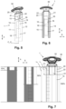
- a measure of having sufficient depth of the U-shaped holder 20 In Fig. 7 , it is illustrated that it is practical if the depth as mentioned, i.e. an average length L 1 of the two protruding wall portions 21, 22 of the U-shaped holder 20 in an axial direction A parallel to the first coupling axis C 1 is chosen so as to be between 10% and 50% of a total length L 2 of the main housing 10 in the axial direction A.
- an average length L 1 of the two protruding wall portions 21, 22 of the U-shaped holder 20 in the axial direction A is at least 50%, and preferably at least 100% of an average distance D 1 between the two protruding wall portions 21, 22 in the sideward direction S
- an average distance D 2 between the front wall 11 and the back wall 12 of the main housing 10 measured along the upper wall 13 of the main housing 10 in a direction T perpendicular to both the axial direction A and the sideward direction S, is larger than the average distance D 1 between the two protruding wall portions 21, 22 of the U-shaped holder 20 in the sideward direction S.
- a first imaginary plane P 1 comprising the first coupling axis C 1 and extending centrally between the front wall 11 and the back wall 12 of the main housing 10 and a second imaginary plane P 2 comprising the first coupling axis C 1 and extending centrally between the two protruding wall portions 21, 22 of the U-shaped holder 20 are indicated by means of dashed lines.
- the functional attachment 30 is separately shown in Fig. 9 .
- the general set-up of the functional attachment 30 is that the functional attachment 30 comprises a base member 31 and a functional personal care unit 32 arranged on the base member 31.
- the functional attachments 30 shown in Figs. 1 and 2 differ from each other as far as the design and the functionality of the functional personal care unit 32 is concerned. Seen from left to right in Figs. 1 and 2 , the following functional personal care units 32 are shown: a shaving unit, a beard trimming unit, a facial brushing unit, and a nose and ear hair trimming unit.
- the specific embodiments of the functional personal care unit 32 of the functional attachment 30 shown in figures are practical examples in the context of the invention, wherein it is to be noted that numerous other options in respect of the design and the functionality of the functional personal care unit 32 are covered by the invention.
- first coupling axis C 1 coincides with a rotation axis of an output shaft of the motor 16, and further if a driving member 19 for transmitting motion to a driven member 41 accommodated in the base member 31 is coupled to or integrated with the output shaft, wherein further a mechanical transmission 42 may be applied between the driven member 41 and a movable portion of the functional personal care unit 32 to convert motion of the driven member 41 into a different motion of the movable portion of the functional personal care unit 32, as illustrated in Fig. 5 .
- the functional attachment 30 further comprises a second coupling member 33, which is arranged in or on the base member 31 and which has a second coupling axis C 2 .
- the second coupling member 33 comprises a projection 34 extending from a bottom wall 35 of the base member 31, as diagrammatically indicated in Fig. 1 in dashed lining, particularly a projection 34 configured to be received in the aperture 24 provided in the upper wall 13 of the main housing 10 when the functional attachment 30 is coupled to the main housing 10.
- the design of the second coupling member 33 involves such a projection 34, indeed, which does not alter the fact that other designs of the second coupling member 33 are feasible in the context of the invention as well.
- the first coupling member 23 and the second coupling member 33 further comprise components which are especially designed to releasably engage on each other by moving the first and second coupling members 23, 33 towards each other along the aligned first and second coupling axes C 1 , C 2 , and to decouple from each other by exerting a decoupling force greater than a predefined threshold force on one of the first and second coupling members 23, 33 in the axial direction A.
- the first coupling member 23 may comprise a U-shaped spring element positioned in the aperture 24, and the second coupling member 33 may comprise two sloped surfaces provided in recesses at diametrically opposite positions on the projection 34, wherein the legs of the U-shaped spring element engage on the sloped surfaces in the coupled condition of the main housing 10 and the functional attachment 30, to mention one of many feasible practical examples.
- An alternative solution to achieve a similar coupling and decoupling functionality is the arrangement of a pair of mutually attracting magnets on the projection 34 and in the aperture 24.
- the projection 34 can be designed so as to allow coupling of the output shaft of the motor 16 to a driven member 41 accommodated in the base member 31 in case the functional attachment 30 is of the type comprising a mechanical system including at least one movable component, such as a mechanical transmission 42, as suggested earlier.
- first coupling member 23 of the main housing 10 and the second coupling member 33 of the functional attachment 30 are the following:
- the design of the handheld personal care device 1 is such that in the coupled condition of the main housing 10 and the functional attachment 30, in which condition the base member 31 of the functional attachment 30 is arranged within the U-shaped holder 20 of the main housing 10, and in which condition the first and second coupling members 23, 33 are in mutual engagement:
- the base member 31 of the functional attachment 30 is supported by the upper wall 13 of the main housing 10 in the coupled condition of the main housing 10 and the functional attachment 30.
- Fig. 10 it can be seen that the base member 31 and the two protruding wall portions 21, 22 of the U-shaped holder 20 are provided with mutually engageable guiding members 25, 50 arranged parallel to the axial direction A.
- the guiding members 25, 50 serve to facilitate the process of coupling the functional attachment 30 to the main housing 10, particularly by realizing the alignment that is appropriate in the process, and constitute visual use cues for correct installation.
- an inner surface of each of the two protruding wall portions 21, 22 of the U-shaped holder 20 is slightly concavely curved.
- an outer surface at opposite sides of the base member 31 of the functional attachment 30 is slightly convexly curved.
- this aspect contributes to coupling robustness in the handheld personal care device 1, besides other aspects already described in the foregoing.
- the handheld personal care device 1 described in the foregoing and illustrated in the figures has a high level of ease of use, combined with the above-mentioned coupling robustness and an advantageous distribution of forces.
- Coupling a functional attachment 30 to the main housing 10 is simply done by moving the functional attachment 30 towards the main housing 10 in an orientation in which the first and second coupling axes C 1 , C 2 are aligned.
- a person who has the functional attachment 30 and the main housing 10 in his/her hands is assisted in realizing the orientation as mentioned by means of the respective guiding members 25, 50 in the U-shaped holder 20 of the main housing 10 and on the base member 31 of the functional attachment 30 engaging each other, and also by means of the projection 34 on the base member 31 being received in the aperture 24 in the upper wall 13 of the main housing 10.
- the base member 31 is securely held in the U-shaped holder 20, and any movable component such as a shaft or gear and/or any electric component in the functional attachment 30 can be driven on the basis of a connection to appropriate interior components of the main housing 10 through the first and second coupling members 23, 33.
- Decoupling the functional attachment 30 from the main housing 10 requires no more than taking hold of the main housing 10 and the functional attachment 30 and pulling the main housing 10 and the functional attachment 30 apart with sufficient force, i.e. with a decoupling force greater than a predefined threshold force.
- FIGs. 11 and 12 a further aspect of the design of the handheld personal care device 1 that helps a person in placing the base member 31 of the functional attachment 30 in the U-shaped holder 20 of the main housing 10 in a correct fashion is illustrated.
- This aspect involves both the upper wall 13 of the main housing 10 and the bottom wall 35 of the base member 31 having an inclined orientation, at a similar angle ⁇ relative to an imaginary plane p extending perpendicularly to the axial direction A.
- FIGs. 13 and 14 another aspect of the design of the handheld personal care device 1 that helps a person in placing the base member 31 of the functional attachment 30 in the U-shaped holder 20 of the main housing 10 in a correct fashion is illustrated.
- This aspect involves both the inner surface of the protruding wall portions 21, 22 of the U-shaped holder 20 and the outer surface of the base member 31 having an appearance that is non-symmetrical in the general configuration of the device 1.
- the base member 31 can be fitted into the U-shaped holder 20 only in a single predefined orientation relative to the U-shaped holder 20.
- a representation of how the base member 31 fits into the U-shaped holder 20 is provided at the bottom of Fig. 14 .
- the design of the base member 31 with a front wall 36, a back wall 37 and two oppositely arranged side walls 38, 39 that interconnect the front wall 36 and the back wall 37 of the base member 31 can also be clearly seen in Fig. 14 . It is illustrated that in the shown example, in the coupled condition of the main housing 10 and the functional attachment 30, the side walls 38, 39 of the base member 31 are each fully supported by a respective one of the two protruding wall portions 21, 22 of the U-shaped holder 20 in the sideward direction S.
- a handheld personal care device 1 comprising a main housing 10 and a functional attachment 30, the functional attachment 30 is couplable to and decouplable from the main housing 10.
- the main housing 10 comprises a first coupling member 23 arranged in an upper wall 13 of the main housing 10.
- the functional attachment 30 comprises a second coupling member 33 arranged in a base member 31 of the functional attachment 30.
- the main housing 10 further comprises a U-shaped holder 20 for receiving and accommodating the base member 31.
- the handheld personal care device 1 is designed to accomplish that in a coupled condition of the main housing 10 and the functional attachment 30, the main housing 10 and the functional attachment 30 are mutually retained in an axial direction A exclusively by mutual engagement of the first and second coupling members 23, 33, and the base member 31 is enclosed and supported by two protruding wall portions 21, 22 of the U-shaped holder 20 in a sideward direction S without being connected or coupled to said two protruding wall portions 21, 22 in the axial direction A.
Landscapes
- Life Sciences & Earth Sciences (AREA)
- Forests & Forestry (AREA)
- Engineering & Computer Science (AREA)
- Mechanical Engineering (AREA)
- Telephone Set Structure (AREA)
- Brushes (AREA)
- Dry Shavers And Clippers (AREA)
Priority Applications (6)
| Application Number | Priority Date | Filing Date | Title |
|---|---|---|---|
| EP21207286.2A EP4177018A1 (fr) | 2021-11-09 | 2021-11-09 | Accouplement et désolidarisation entre un boîtier principal et accessoire fonctionnel d'un dispositif de soins personnels portatif |
| EP22813923.4A EP4429515B1 (fr) | 2021-11-09 | 2022-11-03 | Accouplement et désolidarisation entre un boîtier principal et accessoire fonctionnel d'un dispositif de soins personnels portatif |
| JP2024527117A JP7831597B2 (ja) | 2021-11-09 | 2022-11-03 | ハンドヘルドパーソナルケアデバイスのメインハウジングと機能的アタッチメントとの結合及び分離 |
| CN202280074047.5A CN118215420A (zh) | 2021-11-09 | 2022-11-03 | 手持式个人护理设备的主壳体和功能性附件的联接和解除联接 |
| PCT/EP2022/080633 WO2023083677A1 (fr) | 2021-11-09 | 2022-11-03 | Couplage et découplage d'un boîtier principal et d'une fixation fonctionnelle d'un dispositif de soins personnels portatif |
| KR1020247018901A KR20240099438A (ko) | 2021-11-09 | 2022-11-03 | 핸드헬드 개인 케어 디바이스의 메인 하우징 및 기능성 부착물의 커플링 및 디커플링 |
Applications Claiming Priority (1)
| Application Number | Priority Date | Filing Date | Title |
|---|---|---|---|
| EP21207286.2A EP4177018A1 (fr) | 2021-11-09 | 2021-11-09 | Accouplement et désolidarisation entre un boîtier principal et accessoire fonctionnel d'un dispositif de soins personnels portatif |
Publications (1)
| Publication Number | Publication Date |
|---|---|
| EP4177018A1 true EP4177018A1 (fr) | 2023-05-10 |
Family
ID=78592676
Family Applications (2)
| Application Number | Title | Priority Date | Filing Date |
|---|---|---|---|
| EP21207286.2A Withdrawn EP4177018A1 (fr) | 2021-11-09 | 2021-11-09 | Accouplement et désolidarisation entre un boîtier principal et accessoire fonctionnel d'un dispositif de soins personnels portatif |
| EP22813923.4A Active EP4429515B1 (fr) | 2021-11-09 | 2022-11-03 | Accouplement et désolidarisation entre un boîtier principal et accessoire fonctionnel d'un dispositif de soins personnels portatif |
Family Applications After (1)
| Application Number | Title | Priority Date | Filing Date |
|---|---|---|---|
| EP22813923.4A Active EP4429515B1 (fr) | 2021-11-09 | 2022-11-03 | Accouplement et désolidarisation entre un boîtier principal et accessoire fonctionnel d'un dispositif de soins personnels portatif |
Country Status (5)
| Country | Link |
|---|---|
| EP (2) | EP4177018A1 (fr) |
| JP (1) | JP7831597B2 (fr) |
| KR (1) | KR20240099438A (fr) |
| CN (1) | CN118215420A (fr) |
| WO (1) | WO2023083677A1 (fr) |
Cited By (4)
| Publication number | Priority date | Publication date | Assignee | Title |
|---|---|---|---|---|
| USD998892S1 (en) * | 2023-03-20 | 2023-09-12 | Ningbo HomeBeauty Electrical Appliances Co., Ltd | Electric clipper |
| USD1000706S1 (en) * | 2023-01-06 | 2023-10-03 | Jianxin Xiong | Nose hair trimmer |
| USD1016393S1 (en) * | 2020-10-09 | 2024-02-27 | Panasonic Intellectual Property Management Co., Ltd. | Grooming device holder |
| US20250326142A1 (en) * | 2024-04-19 | 2025-10-23 | Skull Shaver Llc | Holder for electric shaver |
Families Citing this family (2)
| Publication number | Priority date | Publication date | Assignee | Title |
|---|---|---|---|---|
| US20240208092A1 (en) * | 2022-12-21 | 2024-06-27 | Conair Llc | Multiple function hair trimmer |
| EP4670933A1 (fr) | 2024-06-26 | 2025-12-31 | Koninklijke Philips N.V. | Dispositif électrique de coupe de cheveux ayant des modes de fonctionnement et procédé de commutation entre les modes de fonctionnement |
Citations (8)
| Publication number | Priority date | Publication date | Assignee | Title |
|---|---|---|---|---|
| EP0176128A1 (fr) * | 1984-09-12 | 1986-04-02 | Koninklijke Philips Electronics N.V. | Rasoir électrique |
| KR200257871Y1 (ko) | 2001-09-15 | 2001-12-22 | 오태준 | 바리캉 겸용 전기면도기 |
| US6378210B1 (en) * | 2000-03-17 | 2002-04-30 | Roy L. Bickford | Pattern designer shaver system |
| WO2002036314A1 (fr) * | 2000-10-30 | 2002-05-10 | Conair Corporation | Tondeuse a cheveux pourvue d'un assemblage de tete de tondeuse pivotante |
| WO2008062339A1 (fr) | 2006-11-20 | 2008-05-29 | Koninklijke Philips Electronics N.V. | Rasoir rotatif avec une structure de support améliorée pour des têtes de rasage |
| EP2433520A1 (fr) * | 2010-09-27 | 2012-03-28 | Seb S.A. | Epilateur avec tête de massage amovible |
| US20140196292A1 (en) * | 2013-01-11 | 2014-07-17 | Rovcal, LLC | Rotary electric shaver |
| EP3885083A1 (fr) * | 2018-11-23 | 2021-09-29 | Zhejiang Shalom Electric Co., Ltd. | Structure de mise en prise dans une tête de rasoir |
Family Cites Families (1)
| Publication number | Priority date | Publication date | Assignee | Title |
|---|---|---|---|---|
| JPS5861779A (ja) * | 1981-10-09 | 1983-04-12 | 松下電工株式会社 | 電気かみそり |
-
2021
- 2021-11-09 EP EP21207286.2A patent/EP4177018A1/fr not_active Withdrawn
-
2022
- 2022-11-03 CN CN202280074047.5A patent/CN118215420A/zh active Pending
- 2022-11-03 EP EP22813923.4A patent/EP4429515B1/fr active Active
- 2022-11-03 WO PCT/EP2022/080633 patent/WO2023083677A1/fr not_active Ceased
- 2022-11-03 JP JP2024527117A patent/JP7831597B2/ja active Active
- 2022-11-03 KR KR1020247018901A patent/KR20240099438A/ko active Pending
Patent Citations (8)
| Publication number | Priority date | Publication date | Assignee | Title |
|---|---|---|---|---|
| EP0176128A1 (fr) * | 1984-09-12 | 1986-04-02 | Koninklijke Philips Electronics N.V. | Rasoir électrique |
| US6378210B1 (en) * | 2000-03-17 | 2002-04-30 | Roy L. Bickford | Pattern designer shaver system |
| WO2002036314A1 (fr) * | 2000-10-30 | 2002-05-10 | Conair Corporation | Tondeuse a cheveux pourvue d'un assemblage de tete de tondeuse pivotante |
| KR200257871Y1 (ko) | 2001-09-15 | 2001-12-22 | 오태준 | 바리캉 겸용 전기면도기 |
| WO2008062339A1 (fr) | 2006-11-20 | 2008-05-29 | Koninklijke Philips Electronics N.V. | Rasoir rotatif avec une structure de support améliorée pour des têtes de rasage |
| EP2433520A1 (fr) * | 2010-09-27 | 2012-03-28 | Seb S.A. | Epilateur avec tête de massage amovible |
| US20140196292A1 (en) * | 2013-01-11 | 2014-07-17 | Rovcal, LLC | Rotary electric shaver |
| EP3885083A1 (fr) * | 2018-11-23 | 2021-09-29 | Zhejiang Shalom Electric Co., Ltd. | Structure de mise en prise dans une tête de rasoir |
Cited By (4)
| Publication number | Priority date | Publication date | Assignee | Title |
|---|---|---|---|---|
| USD1016393S1 (en) * | 2020-10-09 | 2024-02-27 | Panasonic Intellectual Property Management Co., Ltd. | Grooming device holder |
| USD1000706S1 (en) * | 2023-01-06 | 2023-10-03 | Jianxin Xiong | Nose hair trimmer |
| USD998892S1 (en) * | 2023-03-20 | 2023-09-12 | Ningbo HomeBeauty Electrical Appliances Co., Ltd | Electric clipper |
| US20250326142A1 (en) * | 2024-04-19 | 2025-10-23 | Skull Shaver Llc | Holder for electric shaver |
Also Published As
| Publication number | Publication date |
|---|---|
| JP7831597B2 (ja) | 2026-03-17 |
| JP2024543354A (ja) | 2024-11-21 |
| CN118215420A (zh) | 2024-06-18 |
| WO2023083677A1 (fr) | 2023-05-19 |
| KR20240099438A (ko) | 2024-06-28 |
| EP4429515B1 (fr) | 2025-08-06 |
| EP4429515A1 (fr) | 2024-09-18 |
Similar Documents
| Publication | Publication Date | Title |
|---|---|---|
| EP4177018A1 (fr) | Accouplement et désolidarisation entre un boîtier principal et accessoire fonctionnel d'un dispositif de soins personnels portatif | |
| EP3772394B1 (fr) | Bloc-batterie | |
| US5283921A (en) | Electric toothbrush holder | |
| EP2086729B1 (fr) | Rasoir rotatif avec une structure de support amelioree pour des tetes de rasage | |
| CN101494281B (zh) | 具有带易连接和解除机构的电池组的电气装置 | |
| EP3433906B1 (fr) | Dispositif de commutation de sécurité pour un appareil de soins personnels | |
| EP3463769B1 (fr) | Accessoire pour un dispositif de soins personnels | |
| EP2211429A1 (fr) | Ensemble de prise, prise de fixation et prise de conversion | |
| EP4248833A1 (fr) | Dispositif de commande pour endoscope et endoscope | |
| CN100577120C (zh) | 用于将器具主体连接到从动件组件的系统及口腔护理器具 | |
| JP2003117855A (ja) | 電動工具と電動工具のための電源接続装置と電動工具に電源接続装置が取付けられた電動工具ユニット | |
| EP4197722A1 (fr) | Connexion électrique amovible dans un dispositif de soin personnel portatif | |
| EP3856471B1 (fr) | Ensemble de couplage destiné à être utilisé dans un appareil de soins personnels | |
| JP4383750B2 (ja) | 充電式電動工具におけるフックの取付構造 | |
| US20200130163A1 (en) | Power supply system, power tool system, and power tool | |
| JP5060339B2 (ja) | マグネット式コンセントアダプタ | |
| CN112074373A (zh) | 工具机设备 | |
| EP4516455A1 (fr) | Outil électrique | |
| CN216643783U (zh) | 可手持急停装置、手柄卡托和康复训练设备 | |
| EP1977726A1 (fr) | Vibreur pour massage | |
| CN218802407U (zh) | 便于携带的削发装置 | |
| CN217215238U (zh) | 一种电连接器的护线外壳 | |
| CN211106418U (zh) | 一种打印机 | |
| CN215318842U (zh) | 连接机构及剃刮设备 | |
| CN214352572U (zh) | 一种电动修眉刀 |
Legal Events
| Date | Code | Title | Description |
|---|---|---|---|
| PUAI | Public reference made under article 153(3) epc to a published international application that has entered the european phase |
Free format text: ORIGINAL CODE: 0009012 |
|
| STAA | Information on the status of an ep patent application or granted ep patent |
Free format text: STATUS: THE APPLICATION HAS BEEN PUBLISHED |
|
| AK | Designated contracting states |
Kind code of ref document: A1 Designated state(s): AL AT BE BG CH CY CZ DE DK EE ES FI FR GB GR HR HU IE IS IT LI LT LU LV MC MK MT NL NO PL PT RO RS SE SI SK SM TR |
|
| STAA | Information on the status of an ep patent application or granted ep patent |
Free format text: STATUS: THE APPLICATION IS DEEMED TO BE WITHDRAWN |
|
| 18D | Application deemed to be withdrawn |
Effective date: 20231111 |