EP4177101A1 - Procédé et système de commande de charge, et véhicule - Google Patents
Procédé et système de commande de charge, et véhicule Download PDFInfo
- Publication number
- EP4177101A1 EP4177101A1 EP21851422.2A EP21851422A EP4177101A1 EP 4177101 A1 EP4177101 A1 EP 4177101A1 EP 21851422 A EP21851422 A EP 21851422A EP 4177101 A1 EP4177101 A1 EP 4177101A1
- Authority
- EP
- European Patent Office
- Prior art keywords
- charging
- upper limit
- limit value
- charging current
- value
- Prior art date
- Legal status (The legal status is an assumption and is not a legal conclusion. Google has not performed a legal analysis and makes no representation as to the accuracy of the status listed.)
- Granted
Links
Images


Classifications
-
- B—PERFORMING OPERATIONS; TRANSPORTING
- B60—VEHICLES IN GENERAL
- B60L—PROPULSION OF ELECTRICALLY-PROPELLED VEHICLES; SUPPLYING ELECTRIC POWER FOR AUXILIARY EQUIPMENT OF ELECTRICALLY-PROPELLED VEHICLES; ELECTRODYNAMIC BRAKE SYSTEMS FOR VEHICLES IN GENERAL; MAGNETIC SUSPENSION OR LEVITATION FOR VEHICLES; MONITORING OPERATING VARIABLES OF ELECTRICALLY-PROPELLED VEHICLES; ELECTRIC SAFETY DEVICES FOR ELECTRICALLY-PROPELLED VEHICLES
- B60L53/00—Methods of charging batteries, specially adapted for electric vehicles; Charging stations or on-board charging equipment therefor; Exchange of energy storage elements in electric vehicles
- B60L53/10—Methods of charging batteries, specially adapted for electric vehicles; Charging stations or on-board charging equipment therefor; Exchange of energy storage elements in electric vehicles characterised by the energy transfer between the charging station and the vehicle
- B60L53/14—Conductive energy transfer
-
- B—PERFORMING OPERATIONS; TRANSPORTING
- B60—VEHICLES IN GENERAL
- B60L—PROPULSION OF ELECTRICALLY-PROPELLED VEHICLES; SUPPLYING ELECTRIC POWER FOR AUXILIARY EQUIPMENT OF ELECTRICALLY-PROPELLED VEHICLES; ELECTRODYNAMIC BRAKE SYSTEMS FOR VEHICLES IN GENERAL; MAGNETIC SUSPENSION OR LEVITATION FOR VEHICLES; MONITORING OPERATING VARIABLES OF ELECTRICALLY-PROPELLED VEHICLES; ELECTRIC SAFETY DEVICES FOR ELECTRICALLY-PROPELLED VEHICLES
- B60L53/00—Methods of charging batteries, specially adapted for electric vehicles; Charging stations or on-board charging equipment therefor; Exchange of energy storage elements in electric vehicles
- B60L53/60—Monitoring or controlling charging stations
- B60L53/62—Monitoring or controlling charging stations in response to charging parameters, e.g. current, voltage or electrical charge
-
- B—PERFORMING OPERATIONS; TRANSPORTING
- B60—VEHICLES IN GENERAL
- B60L—PROPULSION OF ELECTRICALLY-PROPELLED VEHICLES; SUPPLYING ELECTRIC POWER FOR AUXILIARY EQUIPMENT OF ELECTRICALLY-PROPELLED VEHICLES; ELECTRODYNAMIC BRAKE SYSTEMS FOR VEHICLES IN GENERAL; MAGNETIC SUSPENSION OR LEVITATION FOR VEHICLES; MONITORING OPERATING VARIABLES OF ELECTRICALLY-PROPELLED VEHICLES; ELECTRIC SAFETY DEVICES FOR ELECTRICALLY-PROPELLED VEHICLES
- B60L53/00—Methods of charging batteries, specially adapted for electric vehicles; Charging stations or on-board charging equipment therefor; Exchange of energy storage elements in electric vehicles
- B60L53/20—Methods of charging batteries, specially adapted for electric vehicles; Charging stations or on-board charging equipment therefor; Exchange of energy storage elements in electric vehicles characterised by converters located in the vehicle
-
- B—PERFORMING OPERATIONS; TRANSPORTING
- B60—VEHICLES IN GENERAL
- B60L—PROPULSION OF ELECTRICALLY-PROPELLED VEHICLES; SUPPLYING ELECTRIC POWER FOR AUXILIARY EQUIPMENT OF ELECTRICALLY-PROPELLED VEHICLES; ELECTRODYNAMIC BRAKE SYSTEMS FOR VEHICLES IN GENERAL; MAGNETIC SUSPENSION OR LEVITATION FOR VEHICLES; MONITORING OPERATING VARIABLES OF ELECTRICALLY-PROPELLED VEHICLES; ELECTRIC SAFETY DEVICES FOR ELECTRICALLY-PROPELLED VEHICLES
- B60L53/00—Methods of charging batteries, specially adapted for electric vehicles; Charging stations or on-board charging equipment therefor; Exchange of energy storage elements in electric vehicles
- B60L53/60—Monitoring or controlling charging stations
- B60L53/63—Monitoring or controlling charging stations in response to network capacity
-
- H—ELECTRICITY
- H02—GENERATION; CONVERSION OR DISTRIBUTION OF ELECTRIC POWER
- H02J—ELECTRIC POWER NETWORKS; CIRCUIT ARRANGEMENTS OR SYSTEMS FOR SUPPLYING OR DISTRIBUTING ELECTRIC POWER; SYSTEMS FOR STORING ELECTRIC ENERGY
- H02J7/00—Circuit arrangements for charging or discharging batteries or for supplying loads from batteries
- H02J7/60—Circuit arrangements for charging or discharging batteries or for supplying loads from batteries including safety or protection arrangements
- H02J7/685—Circuit arrangements for charging or discharging batteries or for supplying loads from batteries including safety or protection arrangements using connection detecting circuits
-
- H—ELECTRICITY
- H02—GENERATION; CONVERSION OR DISTRIBUTION OF ELECTRIC POWER
- H02J—ELECTRIC POWER NETWORKS; CIRCUIT ARRANGEMENTS OR SYSTEMS FOR SUPPLYING OR DISTRIBUTING ELECTRIC POWER; SYSTEMS FOR STORING ELECTRIC ENERGY
- H02J7/00—Circuit arrangements for charging or discharging batteries or for supplying loads from batteries
- H02J7/90—Regulation of charging or discharging current or voltage
- H02J7/94—Regulation of charging or discharging current or voltage in response to battery current
-
- H—ELECTRICITY
- H02—GENERATION; CONVERSION OR DISTRIBUTION OF ELECTRIC POWER
- H02J—ELECTRIC POWER NETWORKS; CIRCUIT ARRANGEMENTS OR SYSTEMS FOR SUPPLYING OR DISTRIBUTING ELECTRIC POWER; SYSTEMS FOR STORING ELECTRIC ENERGY
- H02J2105/00—Networks for supplying or distributing electric power characterised by their spatial reach or by the load
- H02J2105/30—Networks for supplying or distributing electric power characterised by their spatial reach or by the load the load networks being external to vehicles, i.e. exchanging power with vehicles
- H02J2105/33—Networks for supplying or distributing electric power characterised by their spatial reach or by the load the load networks being external to vehicles, i.e. exchanging power with vehicles exchanging power with road vehicles
- H02J2105/37—Networks for supplying or distributing electric power characterised by their spatial reach or by the load the load networks being external to vehicles, i.e. exchanging power with vehicles exchanging power with road vehicles exchanging power with electric vehicles [EV] or with hybrid electric vehicles [HEV]
-
- Y—GENERAL TAGGING OF NEW TECHNOLOGICAL DEVELOPMENTS; GENERAL TAGGING OF CROSS-SECTIONAL TECHNOLOGIES SPANNING OVER SEVERAL SECTIONS OF THE IPC; TECHNICAL SUBJECTS COVERED BY FORMER USPC CROSS-REFERENCE ART COLLECTIONS [XRACs] AND DIGESTS
- Y02—TECHNOLOGIES OR APPLICATIONS FOR MITIGATION OR ADAPTATION AGAINST CLIMATE CHANGE
- Y02T—CLIMATE CHANGE MITIGATION TECHNOLOGIES RELATED TO TRANSPORTATION
- Y02T10/00—Road transport of goods or passengers
- Y02T10/60—Other road transportation technologies with climate change mitigation effect
- Y02T10/70—Energy storage systems for electromobility, e.g. batteries
-
- Y—GENERAL TAGGING OF NEW TECHNOLOGICAL DEVELOPMENTS; GENERAL TAGGING OF CROSS-SECTIONAL TECHNOLOGIES SPANNING OVER SEVERAL SECTIONS OF THE IPC; TECHNICAL SUBJECTS COVERED BY FORMER USPC CROSS-REFERENCE ART COLLECTIONS [XRACs] AND DIGESTS
- Y02—TECHNOLOGIES OR APPLICATIONS FOR MITIGATION OR ADAPTATION AGAINST CLIMATE CHANGE
- Y02T—CLIMATE CHANGE MITIGATION TECHNOLOGIES RELATED TO TRANSPORTATION
- Y02T10/00—Road transport of goods or passengers
- Y02T10/60—Other road transportation technologies with climate change mitigation effect
- Y02T10/7072—Electromobility specific charging systems or methods for batteries, ultracapacitors, supercapacitors or double-layer capacitors
-
- Y—GENERAL TAGGING OF NEW TECHNOLOGICAL DEVELOPMENTS; GENERAL TAGGING OF CROSS-SECTIONAL TECHNOLOGIES SPANNING OVER SEVERAL SECTIONS OF THE IPC; TECHNICAL SUBJECTS COVERED BY FORMER USPC CROSS-REFERENCE ART COLLECTIONS [XRACs] AND DIGESTS
- Y02—TECHNOLOGIES OR APPLICATIONS FOR MITIGATION OR ADAPTATION AGAINST CLIMATE CHANGE
- Y02T—CLIMATE CHANGE MITIGATION TECHNOLOGIES RELATED TO TRANSPORTATION
- Y02T90/00—Enabling technologies or technologies with a potential or indirect contribution to GHG emissions mitigation
- Y02T90/10—Technologies relating to charging of electric vehicles
- Y02T90/12—Electric charging stations
-
- Y—GENERAL TAGGING OF NEW TECHNOLOGICAL DEVELOPMENTS; GENERAL TAGGING OF CROSS-SECTIONAL TECHNOLOGIES SPANNING OVER SEVERAL SECTIONS OF THE IPC; TECHNICAL SUBJECTS COVERED BY FORMER USPC CROSS-REFERENCE ART COLLECTIONS [XRACs] AND DIGESTS
- Y02—TECHNOLOGIES OR APPLICATIONS FOR MITIGATION OR ADAPTATION AGAINST CLIMATE CHANGE
- Y02T—CLIMATE CHANGE MITIGATION TECHNOLOGIES RELATED TO TRANSPORTATION
- Y02T90/00—Enabling technologies or technologies with a potential or indirect contribution to GHG emissions mitigation
- Y02T90/10—Technologies relating to charging of electric vehicles
- Y02T90/14—Plug-in electric vehicles
-
- Y—GENERAL TAGGING OF NEW TECHNOLOGICAL DEVELOPMENTS; GENERAL TAGGING OF CROSS-SECTIONAL TECHNOLOGIES SPANNING OVER SEVERAL SECTIONS OF THE IPC; TECHNICAL SUBJECTS COVERED BY FORMER USPC CROSS-REFERENCE ART COLLECTIONS [XRACs] AND DIGESTS
- Y02—TECHNOLOGIES OR APPLICATIONS FOR MITIGATION OR ADAPTATION AGAINST CLIMATE CHANGE
- Y02T—CLIMATE CHANGE MITIGATION TECHNOLOGIES RELATED TO TRANSPORTATION
- Y02T90/00—Enabling technologies or technologies with a potential or indirect contribution to GHG emissions mitigation
- Y02T90/10—Technologies relating to charging of electric vehicles
- Y02T90/16—Information or communication technologies improving the operation of electric vehicles
- Y02T90/167—Systems integrating technologies related to power network operation and communication or information technologies for supporting the interoperability of electric or hybrid vehicles, i.e. smartgrids as interface for battery charging of electric vehicles [EV] or hybrid vehicles [HEV]
Definitions
- the present application relates to the technical field of new energy vehicles and, more particularly, to a charging control method and system, and a vehicle.
- APP Application
- HUT Head Unit System
- the on-board charging guns are divided into 10A charging guns and 16A charging guns.
- the 10A charging gun may be directly connected to the conventional household socket, while the 16A charging gun cannot be directly connected to the conventional household socket.
- the present application aims to provide a charging control method and system, and a vehicle, so as to solve the problem that a current control manner for charging a vehicle battery pack is unreasonable in the prior art, and a user is prone to complain.
- charging the battery pack according to the smaller value of the first charging current upper limit value and the second charging current upper limit value includes: when the charging device includes the charging gun of the charging pile, setting the preset charging current value as a third charging current upper limit value, and charging the battery pack according to the smaller value of the first charging current upper limit value and the second charging current upper limit value, wherein the third charging current upper limit value is a charging current upper limit value of the on-board charger.
- charging the battery pack according to the smallest value of the first charging current upper limit value, the second charging current upper limit value and the preset charging current value includes:
- the vehicle further includes a vehicle controller, the vehicle controller is electrically connected to the on-board charger, and before when it is detected that the charging device is connected, determining the type of the charging device, the first charging current upper limit value of the charging device, the second charging current upper limit value of the battery pack and the preset charging current value, the method further includes:
- different types of charging devices are configured with resistor modules of different resistance values, and the charging connection confirm signal includes the resistance value of the resistor module; and determining the type of the charging device includes:
- Another object of the embodiment of the present application also aims to provide a charging control system applied to an on-board charger of a vehicle, wherein the vehicle further includes a battery pack, and the system includes:
- the first charging module is specifically configured for, when the charging device includes the charging gun of the charging pile, setting the preset charging current value as a third charging current upper limit value, and charging the battery pack according to the smaller value of the first charging current upper limit value and the second charging current upper limit value, wherein the third charging current upper limit value is a charging current upper limit value of the on-board charger.
- the second charging module includes:
- the vehicle further includes a vehicle controller, the vehicle controller is electrically connected to the on-board charger, and the system further includes:
- the charging connection confirm signal includes the resistance value of the resistor module; and the determining module includes:
- Yet another object of the present application also aims to provide a vehicle, wherein the vehicle includes an on-board charger, the vehicle further includes a battery pack, and the vehicle further includes the charging control system as described above.
- the charging control method, the charging control system and the vehicle according to the present application have the following advantages: when it is detected that the charging device is connected, the type of the charging device, the first charging current upper limit value of the charging device, the second charging current upper limit value of the battery pack and the preset charging current value are determined; when the charging device includes the charging gun of the charging pile, the battery pack is charged according to the smaller value of the first charging current upper limit value and the second charging current upper limit value; and when the charging device includes the on-board charging gun, the battery pack is charged according to the smallest value of the first charging current upper limit value, the second charging current upper limit value and the preset charging current value.
- the battery pack When the battery pack is charged by using the charging gun of the charging pile, the battery pack is charged according to the smaller value of the first charging current upper limit value of the charger and the second charging current upper limit value of the battery pack, so that the charging efficiency is improved to the greatest extent, and the charging time is shortened on the premise of ensuring safety, and a situation that the charging time is prolonged as the charging current is set to be too small is avoided; and when the battery pack is charged by using the on-board charging gun, the battery pack is charged according to the smallest value of the first charging current upper limit value of the charger, the second charging current upper limit value of the battery pack, and the preset charging current value, which meets the personalized charging requirements of the users on the premise of ensuring the safety.
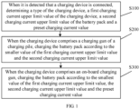
- FIG. 1 shows a flow chart of a charging control method according to an embodiment of the present application.
- the charging control method according to the embodiment of the present application is applied to an on-board charger of a vehicle, and the vehicle further includes a battery pack, wherein the method includes steps S100 to S300.
- the On-board charger is in communication connection with a vehicle controller of the vehicle and a Battery Management System (BMS) of the battery pack.
- BMS Battery Management System
- the on-board charger may dynamically adjust a charging current or voltage parameters according to data according to the BMS, execute corresponding actions and complete a charging process.
- the on-board charger may also communicate with the vehicle controller through a high-speed Controller Area Network (CAN), upload a working state, working parameters and fault warning information of the charger, and receive control commands to start charging or stop charging.
- CAN Controller Area Network
- the on-board charger may ensure that a temperature, a charging voltage and a current of the battery pack do not exceed allowable values; and has a function of limiting a voltage of a single battery, and automatically and dynamically adjusts the charging current according to battery information of the BMS.
- the on-board charger may also automatically judge whether a charging device and a charging cable are correctly connected.
- the on-board charger may allow the charging process to be started only when the on-board charger is correctly connected to a charging pile and the battery. When the charger detects that the connection with the charging pile or the battery is abnormal, the charging is immediately stopped. In addition, the vehicle cannot be started before the charger is connected to the power battery.
- Step S 100 when it is detected that a charging device is connected, determining a type of the charging device, a first charging current upper limit value of the charging device, a second charging current upper limit value of the battery pack and a preset charging current value.
- the charging device refers to a device for charging the battery pack, and may be specifically classified into an on-board charging gun and a charging gun of a charging pile.
- the on-board charging gun is independent charging device and may be directly connected to a power grid through a gun holder or a socket; while the charging gun of the charging pile includes a gun head and a charging pile electrically connected to the gun head.
- Different connection signals may be generated when different types of charging guns are plugged in a charging port of the on-board charger connected to the battery pack.
- a connection signal of the charging device is received, it is indicated that the charging device is plugged in the charging port, so that it may be detected the charging device is connected, indicating that the battery pack needs to be charged.
- the specific type of the charging device connected to the on-board may be determined according to the connection signal, so as to determine a current upper limit value that the charging device may allow to supply power subsequently.
- the charging gun of each type has a corresponding maximum charging current, and the maximum charging currents allowed by the charging guns of different types are different, so that after the type of the charging device is determined, the charging current upper limit value of the charging device, that is, the first charging current upper limit value, may also be determined. Because the on-board charger of the battery pack is in communication connection with the battery management system, the charging current upper limit value of the battery pack, that is, the second charging current upper limit value, may be acquired through the battery management system.
- the vehicle on-board charger is in communication connection with the vehicle controller through the CAN network, and the vehicle controller may receive charging current setting through the APP end or the Head Unit System end, the on-board charger may acquire the current value, that is, the above preset charging current value, determined by the above charging current setting.
- the preset charging current value may be set by a user according to the needs of the user.
- Step S200 when the charging device includes a charging gun of a charging pile, charging the battery pack according to the smaller value of the first charging current upper limit value and the second charging current upper limit value.
- step S200 when the battery pack of the vehicle is charged by using the charging gun of the charging pile, it is indicated that the user wishes to perform quick charging at current.
- the battery pack is charged by using the smaller value of the first charging current upper limit value and the second charging current upper limit value, so that the battery pack may be charged by using the maximum charging current and the maximum charging power on the premise of ensuring the power utilization safety, thereby reducing the problem of prolonging the charging time of the charging pile due to the use of the smaller preset charging current default in the vehicle or set by the user, reducing the charging time, and avoiding customer complaints.
- step S200 it is equivalent to neglect the original charging current setting of the vehicle when charging is performed by using the charging pile, so as to achieve a quick charging effect.
- step S300 since the user is likely to set the charging current based on the actual need or actual situation of the user when the vehicle is charged by using the on-board charging gun, the user wants to charge the vehicle with the set preset charging current.
- charging the battery pack with the smallest value of the first charging current upper limit value, the second charging current upper limit value and the preset charging current value may ensure that the battery pack is charged with the preset charging current value default in the vehicle or set by the user on the premise of ensuring the power utilization safety, so as to meet the actual charging requirements of the user.
- the charging control method has the following advantages: when the battery pack is charged by using the charging gun of the charging pile, the battery pack is charged according to the smaller value of the first charging current upper limit value of the charger and the second charging current upper limit value of the battery pack, so that the charging efficiency is improved to the greatest extent, and the charging time is shortened on the premise of ensuring safety, and a situation that the charging time is prolonged as the charging current is set to be too small is avoided; and when the battery pack is charged by using the on-board charging gun, the battery pack is charged according to the smallest value of the first charging current upper limit value of the charging device, the second charging current upper limit value of the battery pack, and the preset charging current value, which meets the personalized charging requirements of the users on the premise of ensuring the safety.
- the vehicle further includes a vehicle controller, and the vehicle controller is electrically connected to the on-board charger.
- the charging control method according to the embodiment of the present application further includes steps S1001 to S1002 before the step S100.
- Step S1001 when it is detected that the charging device is plugged in the on-board charger, and when a charging connection confirm signal and a control confirm signal are received within a preset time, sending a charging signal to the vehicle controller, so that the vehicle controller executes a charging power-on process and determines that the charging device is connected.
- the charging connection confirm signal is a signal for determining that the charging device is normally connected to a power grid
- the control confirm signal is a signal for determining that the on-board charger, the vehicle and the charging device are normally connected.
- the on-board charger is reflected. Since the on-board charger is electrically connected to the vehicle controller of the vehicle, after the charging device is plugged in the on-board charger, the vehicle controller may be awakened, and Connection Confirm (CC) and charging Control Piolt (CP) may be performed.
- CC Connection Confirm
- CP charging Control Piolt
- the charging connection confirm is used for determining whether the on-board charger is normally connected to the power grid, and specifically, it is judged whether the charging device is plugged by detecting a voltage condition of the CC signal; while the charging control confirm is used for determining whether the on-board charger is normally connected to the vehicle, specifically, after the CC connection confirm signal is normal, the charging device, the on-board charger and a control system related to vehicle charging perform self-checking and mutual checking, and perform control connection confirmation, and a control connection condition is determined through a voltage of the CP signal.
- the CP signal is a PWM signal with a frequency of 1 KHz, and a maximum output current of the on-board charger may be set through a duty ratio of the CP signal.
- the preset time is a preset longest waiting time for waiting for a charging line to be ready after the charging device is plugged in the on-board charger, and when the charging confirmation is not completed after the preset time exceeds, the entire vehicle enters a state of dormancy.
- the preset time is a value to be determined (TBD), and may be set as 3 seconds or 10 minutes, for example, and may be specifically set as needed.
- a charging signal is sent to the vehicle controller only when the charging connection confirm signal and the control confirm signal are received within the preset time, so that the vehicle controller executes the charging power-on process, and determines that the charging device is connected, and then executes subsequent charging operation, thereby avoiding an accident such as fire, explosion, and the like caused by an excessively large contact resistance between the charging device and the socket due to forced charging when the charging device is not plugged.
- Step S1002 when it is detected that the charging device is plugged into the on-board charger, and when the charging connection confirm signal or the control confirm signal is not received within the preset time, sending a power-off signal to the vehicle controller, so that the vehicle controller executes a charging power-off process.
- step S1002 when the charging connection confirm signal or the control confirm signal is not received within the preset time, it is determined that the charging line cannot be prepared, and the entire vehicle is already in a wake-up state in this case. Based on the consideration of saving electric energy, the on-board charger sends the power-off signal to the vehicle controller, so that the vehicle controller executes the charging power-off process.
- the vehicle controller executes the charging power-on process and determines that the charging device is connected, and then executes the subsequent charging operation, thereby avoiding the accident such as fire, explosion, and the like caused by the excessively large contact resistance between the charging device and the socket due to forced charging when the charging device is not plugged.
- different types of charging devices are configured with resistor modules of different resistance values
- the charging connection confirm signal includes the resistance value of the resistor module
- the determining the type of the charging device includes: determining a resistance value of the charging device according to the charging connection confirm signal; and determining the type of the charging device according to the resistance value.
- the resistor modules of different resistance values have different cable thicknesses. For example, when the resistance value is 1.5 KS2, it is indicated that the cable capacity of the charging device is 10 A, and the corresponding charging gun is a 10A on-board charging gun. When the resistance value is 680 S2, it is indicated that the current capacity value of the cable of the charging device is 16 A, and the corresponding charging gun is a 16A on-board charging gun. When the resistance value is 220 S2, it is indicated that the current capacity value of the cable of the charging device is 32 A, and the corresponding charging gun is a charging gun of a charging pile. In practical applications, the resistor modules are RC resistors.
- the step S200 specifically includes step S201.
- Step S201 when the charging device includes the charging gun of the charging pile, setting the preset charging current value as a third charging current upper limit value, and charging the battery pack according to the smaller value of the first charging current upper limit value and the second charging current upper limit value, wherein the third charging current upper limit value is a charging current upper limit value of the on-board charger.
- the on-board charger adjusts the set default value of the charging current to the charging current upper limit value, i.e., the third charging current upper limit value, that the on-board charger may bear, so that the vehicle may be charged with the maximum charging current and the maximum charging power.
- the charging current upper limit value i.e., the third charging current upper limit value
- the third charging current upper limit value is 16 A.
- the third charging current upper limit value is 32 A.
- the step S300 includes steps S301 to S303: Step S301: when the charging device includes a10A on-board charging gun, charging the battery pack according to the smallest value of the first charging current upper limit value, the preset charging current value and the second charging current upper limit value.
- the 10A on-board charging gun may be directly plugged into a household socket, and a maximum allowable charging current of the 10A on-board charging gun is 8 A, which is smaller than a maximum operating current of the household socket, when it is determined that the charging device connected to the on-board charger is the 10A on-board charging gun, the battery pack is directly charged according to the smallest value of the first charging current upper limit value of the charging device, the preset charging current value, and the second charging current upper limit value of the battery pack acquired in the step S 100, which may charge the battery pack according to the actual use requirement of the user on the premise of ensuring the use safety.
- Step S302 when the charging device includes a 16A on-board charging gun, and when the preset charging current value is greater than a fourth charging current upper limit value, charging the battery pack according to the smallest value of the first charging current upper limit value, the second charging current upper limit value and the fourth charging current upper limit value; wherein, the fourth charging current upper limit value is an operating current upper limit value of the household socket.
- step S302 since the 16A on-board charging gun cannot be directly plugged into the household socket, some users privately repack the conventional household socket, such that the conventional household socket may be connected to the 16A charging gun.
- a maximum allowable charging current of the 16A on-board charging gun is 13 A, which is greater than the maximum operating current of the household socket, the repacked socket is easy to generate heat, burn or even cause fire after being connected to the 16A on-board charging gun.
- the charging device connected to the on-board charger is a 16A on-board charging gun
- the battery pack is charged directly according to the smallest value of the first charging current upper limit value of the charging device, the second charging current upper limit value of the battery pack and the maximum operating current of the household socket, which are acquired in the step S100, so that the vehicle may be charged according to the actual use requirements of the user on the premise of guaranteeing the use safety no matter the user uses the 16A on-board charging gun to charge the battery pack through the repacked household socket.
- the fourth charging current upper limit value is 10 A.
- the vehicle controller may be triggered to send a prompt message to a display unit of the vehicle, so as to display a current charging state on a central control display screen or an instrument panel.
- the charging state includes a charging current value.
- Step S303 when the charging device includes the16A on-board charging gun, and when the preset charging current value is less than or equal to the fourth charging current upper limit value, charging the battery pack according to the smallest value of the first charging current upper limit value, the second charging current upper limit value and the preset charging current value.
- step S303 in order to avoid power utilization dangers caused by the fact that the user charges the vehicle by using the repacked household socket for the 16A on-board charging gun to be plugged in, when it is determined that the charging device connected to the on-board charger is a 16A on-board charging gun, if the preset charging current value is less than or equal to the maximum operating current of the household socket, the battery pack is charged directly according to the smallest value of the first charging current upper limit value of the charging device, the preset charging current value and the second charging current upper limit value of the battery pack, which are acquired in the step S 100, so that the vehicle may be charged according to the actual use requirements of the user on the premise of guaranteeing the use safety no matter the user uses the 16A on-board charging gun to charge the battery pack through the repacked household socket.
- different charging current determining modes are set for different types of on-board charging guns, so that the user may charge the vehicles according to the actual use requirements of the user on the premise of ensuring the use safety when charging the vehicles with the on-board charging gun, thus avoiding the problem of power utilization dangers caused by using the repacked household socket to plug the 16A on-board charging gun to charge the vehicle.
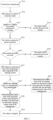
- FIG. 2 shows a flow chart of a charging control method according to a preferred embodiment of the present application.
- the charging control method according to the embodiment of the present application is applied to an on-board charger of a vehicle, the vehicle further includes a battery pack and a vehicle controller, and the vehicle controller is electrically connected to the on-board charger, wherein the method includes steps S211 to S216.
- Step S211 when it is detected that the charging device is plugged in the on-board charger, and when a charging connection confirm signal and a control confirm signal are received within a preset time, sending a charging signal to the vehicle controller, so that the vehicle controller executes a charging power-on process and determines that the charging device is connected.
- step S211 reference may be made to the detailed description of the step S1001, and details are not described herein again.
- Step S212 when it is detected that the charging device is plugged in the on-board charger, and when the charging connection confirm signal or the control confirm signal is not received within the preset time, sending a power-off signal to the vehicle controller, so that the vehicle controller executes a charging power-off process.
- step S212 reference may be made to the detailed description of the step S1002, and details are not described herein again.
- Step S213 when it is detected that a charging device is connected, determining a type of the charging device, a first charging current upper limit value of the charging device, a second charging current upper limit value of the battery pack and a preset charging current value.
- step S213 reference may be made to the detailed description of the step S100, and details are not described herein again.
- Step S214 when the charging device includes the charging gun of the charging pile, setting the preset charging current value as a third charging current upper limit value, and charging the battery pack according to the smaller value of the first charging current upper limit value and the second charging current upper limit value, wherein the third charging current upper limit value is a charging current upper limit value of the on-board charger.
- step S214 reference may be made to the detailed description of the step S201, and details are not described herein again.
- Step S215 when the charging device includes a10A on-board charging gun, charging the battery pack according to the smallest value of the first charging current upper limit value, the preset charging current value and the second charging current upper limit value.
- step S215 reference may be made to the detailed description of the step S301, and details are not described herein again.
- Step S216 when the charging device includes a 16A on-board charging gun, and when the preset charging current value is greater than a fourth charging current upper limit value, charging the battery pack according to the smallest value of the first charging current upper limit value, the second charging current upper limit value and the fourth charging current upper limit value; wherein, the fourth charging current upper limit value is an operating current upper limit value of the household socket.
- step S216 reference may be made to the detailed description of the step S302, and details are not described herein again.
- Step S217 when the charging device includes the16A on-board charging gun, and when the preset charging current value is less than or equal to the fourth charging current upper limit value, charging the battery pack according to the smallest value of the first charging current upper limit value, the second charging current upper limit value and the preset charging current value.
- step S217 reference may be made to the detailed description of the step S303, and details are not described herein again.
- the charging control method has the following advantages: when the battery pack is charged by using the charging gun of the charging pile, the battery pack is charged according to the smaller value of the first charging current upper limit value of the charger and the second charging current upper limit value of the battery pack, so that the charging efficiency is improved to the greatest extent, and the charging time is shortened on the premise of ensuring safety, and a situation that the charging time is prolonged as the charging current is set to be too small is avoided; and when the battery pack is charged by using the on-board charging gun, different charging current determining modes are set for different types of on-board charging guns, so that the user may charge the vehicles according to the actual use requirements of the user on the premise of ensuring the use safety when charging the vehicles with the on-board charging gun, thus avoiding the problem of power utilization dangers caused by using the repacked household socket to plug the16A on-board charging gun to charge the vehicle.
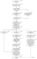
- FIG. 3 shows a flow chart of implementing the charging control method according to the embodiment of the present application.
- step S311 it is detected whether the charging gun is plugged in for connection, and when it is detected that the charging gun is connected, step S312 is performed.
- step S312 the OBC detects CC and CP connection states, and then step S313 is performed.
- step S313 it is detected whether the connection confirm signal and the control confirm signal are received within 3 seconds to determine whether the CC and the CP are normally connected; and if so, step S314 is performed; otherwise, step S315 is performed.
- step S314 the vehicle executes the power-on process under the control of the vehicle controller.
- step S315 the vehicle executes the power-off process under the control of the vehicle controller.
- step S316 it is determined whether the vehicle is successfully powered on; if so, step S317 is performed; otherwise, step S318 is performed to execute the power-off process.
- step S317 the OBC detects a connection type of the charging gun and a magnitude of the charging current, and then step S319 is performed.
- step S319 it is determined through the connection type determined in step S317 whether the charging gun connected to the on-board charger is a charging gun of a charging pile; if yes, step S320 is performed; otherwise, step S321 is performed.
- step S320 the smaller value of the maximum current value allowed to be input by the BMS and the allowable charging current value of the charging gun is determined.
- step S321 the smallest value of the maximum current value allowed to be input by the BMS, the allowable charging current value of the charging gun, and the set charging current is determined.
- step S322 the battery pack is charged according to the smaller value or the smallest value determined in step S320 or S321.
- FIG. 4 shows a flow chart of implementing the charging control method according to the preferred embodiment of the present application.
- step 411 it is detected whether a charging gun is plugged in for connection, and when it is detected that the charging gun is connected, step S412 is performed.
- step 412 the OBC detects CC and CP connection states, and then step S413 is performed.
- step S413 it is detected whether the charging connection confirm signal and the control confirm signal are received within 3 seconds to determine whether the CC and the CP are normally connected; and if so, step S414 is performed; otherwise, step S415 is performed.
- step S414 the vehicle executes the power-on process under the control of the vehicle controller.
- step S415 the vehicle executes the power-off process under the control of the vehicle controller.
- step S416 it is determined whether the vehicle is successfully powered on; if so, step S417 is performed; otherwise, step S415 is performed to execute the power-off process.
- step 417 the OBC detects a connection type of the charging gun and a magnitude of the charging current, and then step S419 is performed.
- step S418 the specific type of the charging gun connected to the on-board charger is determined by the connection type determined in step S417.
- step S419 if it is determined that the charging gun connected to the on-board charger is a 10A on-board charging gun, step S424 is performed.
- step S420 if it is determined that the charging gun connected to the on-board charger is a 16A on-board charging gun, step S421 is performed.
- step S421 the OBC determines a magnitude of the preset charging current value, and then step S422 is performed to determine whether the charging current setting value is greater than 10 A; if so, step S423 is performed; otherwise, step S424 is performed directly.
- step S423 the on-board charger defaults the preset charging current to 10 A, and then step S424 is performed.
- step S424 the smallest value of the maximum current value allowed to be input by the BMS, the allowable charging current value of the charging gun, and the set charging current is determined.
- step S425 if it is determined that the charging gun connected to the on-board charger is a charging gun of a charging pile, step S426 is performed.
- step S426 the on-board charger defaults the preset charging current to 32 A, and then step S427 is performed.
- step S427 the smaller value of the maximum current value allowed to be input by the BMS and the allowable charging current value of the charging gun is determined.
- step S428 the battery pack is charged by the vehicle according to the smaller value or the smallest value determined in step S424 or S427.
- FIG. 5 shows a schematic structural diagram of the charging control system according to an embodiment of the present application.
- the system includes:
- the determining module 51 determines the first charging current upper limit value of the charging device, the second charging current upper limit value of the battery pack and the preset charging current; when the charging device is the charging gun of the charging pile, the first charging module 52 charges the battery pack according to the smaller value of the first charging current upper limit value and the second charging current upper limit value; and when the charging device is the on-board charging gun, the second charging module 53 charges the battery pack according to the smallest value of the first charging current upper limit value, the second charging current upper limit value and the preset charging current value.
- the battery pack When the battery pack is charged by using the charging gun of the charging pile, the battery pack is charged according to the smaller value of the first charging current upper limit value of the charger and the second charging current upper limit value of the battery pack, so that the charging efficiency is improved to the greatest extent, and the charging time is shortened on the premise of ensuring safety, and a situation that the charging time is prolonged as the charging current is set to be too small is avoided; and when the battery pack is charged by using the on-board charging gun, the battery pack is charged according to the smallest value of the first charging current upper limit value of the charger, the second charging current upper limit value of the battery pack, and the preset charging current value, which meets the personalized charging requirements of the users on the premise of ensuring the safety.
- the first charging module 52 is specifically configured for, when the charging device includes the charging gun of the charging pile, setting the preset charging current value as a third charging current upper limit value, and charging the battery pack according to the smaller value of the first charging current upper limit value and the second charging current upper limit value, wherein the third charging current upper limit value is a charging current upper limit value of the on-board charger.
- the first charging module 52 is specifically configured for, when the charging device includes the charging gun of the charging pile, setting the preset charging current value as a third charging current upper limit value, and charging the battery pack according to the smaller value of the first charging current upper limit value and the second charging current upper limit value, wherein the third charging current upper limit value is a charging current upper limit value of the on-board charger.
- the second charging module 53 includes:
- the vehicle further includes a vehicle controller, the vehicle controller is electrically connected to the on-board charger, and the system further includes:
- different types of charging devices are configured with resistor modules of different resistance values, and the charging connection confirm signal includes the resistance value of the resistor module;
- Yet another object of the present application also aims to provide a vehicle, wherein the vehicle includes an on-board charger, the vehicle further includes a battery pack, and the vehicle further includes the charging control system as described above.
- the charging control system and the vehicle have the same advantages as that of the above-mentioned charging control method relative to the prior art, which will not be elaborated herein.
- the charging control and the vehicle when the battery pack is charged by using the charging gun of the charging pile, the battery pack is charged according to the smaller value of the first charging current upper limit value of the charger and the second charging current upper limit value of the battery pack, so that the charging efficiency is improved to the greatest extent, and the charging time is shortened on the premise of ensuring safety, and a situation that the charging time is prolonged as the charging current is set to be too small is avoided; and when the battery pack is charged by using the on-board charging gun, the battery pack is charged according to the smallest value of the first charging current upper limit value of the charger, the second charging current upper limit value of the battery pack, and the preset charging current value, which meets the personalized charging requirements of the users on the premise of ensuring the safety.
- Each component embodiment of the present application may be implemented by hardware, or by software modules that are operated on one or more processors, or by a combination thereof.
- a person skilled in the art should understand that some or all of the functions of some or all of the components of the computing-processing device according to the embodiments of the present application may be implemented by using a microprocessor or a digital signal processor (DSP) in practice.
- DSP digital signal processor
- the present application may also be implemented as device or apparatus programs (for example, computer programs and computer program products) for implementing part of or the whole of the method described herein. Such programs for implementing the present application may be stored in a computer-readable medium, or may be in the form of one or more signals. Such signals may be downloaded from an Internet website, or provided on a carrier signal, or provided in any other forms.
- FIG. 6 shows a computing-processing device that can implement the method according to the present application.
- the computing-processing device traditionally includes a processor 1010 and a computer program product or computer-readable medium in the form of a memory 1020.
- the memory 1020 may be electronic memories such as flash memory, Electrically Erasable Programmable Read Only Memory (EEPROM), EPROM, hard disk or ROM.
- the memory 1020 has a storage space 1030 of a program code 1031 for implementing any steps of the above method.
- the storage space 1030 for program code may contain program codes 1031 for individually implementing each of the steps of the above method. Those program codes may be read from one or more computer program products or be written into the one or more computer program products.
- These computer program products include program code carriers such as hard disks, compact disks (CD), memory cards, or floppy disks.
- Such computer program products are usually portable or fixed storage units as shown in FIG. 7 .
- the storage unit may have storage segments or storage spaces with similar arrangement to the memory 1020 of the computing-processing device in FIG. 6 .
- the program codes may for example be compressed in a suitable form.
- the storage unit contains a computer-readable code 1031', which can be read by a processor like 1010. When those codes are executed by the computing-processing device, the codes cause the computing-processing device to implement each of the steps of the method described above.
- any reference signs between parentheses should not be construed as limiting the claims.
- the word “comprise” does not exclude elements or steps that are not listed in the claims.
- the word “a” or “an” preceding an element does not exclude the existing of a plurality of such elements.
- the present application may be implemented by means of hardware comprising several different elements and by means of a properly programmed computer. In unit claims that list several devices, some of those apparatuses may be embodied by the same item of hardware.
- the words first, second, third and so on do not denote any order. Those words may be interpreted as names.
Landscapes
- Engineering & Computer Science (AREA)
- Power Engineering (AREA)
- Transportation (AREA)
- Mechanical Engineering (AREA)
- Charge And Discharge Circuits For Batteries Or The Like (AREA)
- Electric Propulsion And Braking For Vehicles (AREA)
Applications Claiming Priority (2)
| Application Number | Priority Date | Filing Date | Title |
|---|---|---|---|
| CN202010754831.3A CN113135108B (zh) | 2020-07-30 | 2020-07-30 | 一种充电控制方法、系统及车辆 |
| PCT/CN2021/103664 WO2022022212A1 (fr) | 2020-07-30 | 2021-06-30 | Procédé et système de commande de charge, et véhicule |
Publications (3)
| Publication Number | Publication Date |
|---|---|
| EP4177101A1 true EP4177101A1 (fr) | 2023-05-10 |
| EP4177101A4 EP4177101A4 (fr) | 2024-03-20 |
| EP4177101B1 EP4177101B1 (fr) | 2025-08-20 |
Family
ID=76809262
Family Applications (1)
| Application Number | Title | Priority Date | Filing Date |
|---|---|---|---|
| EP21851422.2A Active EP4177101B1 (fr) | 2020-07-30 | 2021-06-30 | Procédé et système de commande de charge, et véhicule |
Country Status (4)
| Country | Link |
|---|---|
| US (1) | US12202368B2 (fr) |
| EP (1) | EP4177101B1 (fr) |
| CN (1) | CN113135108B (fr) |
| WO (1) | WO2022022212A1 (fr) |
Families Citing this family (9)
| Publication number | Priority date | Publication date | Assignee | Title |
|---|---|---|---|---|
| CN114421638B (zh) * | 2022-01-24 | 2025-07-25 | 中国矿业大学 | 全空间磁耦合无线局域传能系统及其磁能调控方法 |
| CN114801871A (zh) * | 2022-03-18 | 2022-07-29 | 西安特来电领充新能源科技有限公司 | 充放电控制方法、车载充电机及终端设备 |
| CN117621892A (zh) * | 2022-08-19 | 2024-03-01 | 长城汽车股份有限公司 | 一种车辆充电的方法、装置、存储介质及车辆 |
| CN115366729B (zh) * | 2022-09-16 | 2024-12-13 | 福建百城新能源科技有限公司 | 一种可自动识别车辆vin码的直流充电方法以及系统 |
| CN115570996A (zh) * | 2022-10-09 | 2023-01-06 | 合众新能源汽车有限公司 | 动力电池充电方法及装置 |
| CN116442816A (zh) * | 2023-03-30 | 2023-07-18 | 三一汽车起重机械有限公司 | 充电控制方法、系统、电动作业机械及电子设备 |
| CN117022020A (zh) * | 2023-08-01 | 2023-11-10 | 深蓝汽车科技有限公司 | 用于延缓动力电池寿命衰减的充电方法、装置、设备及介质 |
| CN118082587B (zh) * | 2024-04-24 | 2024-06-25 | 深圳时代能创能源科技有限公司 | 一种交流充电桩的智能充电控制方法、系统、设备及介质 |
| CN120828693B (zh) * | 2025-09-18 | 2025-12-23 | 潍柴动力股份有限公司 | 一种电动车辆的充电电流分配方法、装置及电动车辆 |
Family Cites Families (19)
| Publication number | Priority date | Publication date | Assignee | Title |
|---|---|---|---|---|
| US8054039B2 (en) | 2008-12-19 | 2011-11-08 | GM Global Technology Operations LLC | System and method for charging a plug-in electric vehicle |
| DE102011008675A1 (de) | 2011-01-15 | 2012-07-19 | Daimler Ag | Verfahren zum Aufladen einer Batterie eines Fahrzeuges |
| CN203942309U (zh) * | 2014-05-29 | 2014-11-12 | 长城汽车股份有限公司 | 电动汽车充电系统 |
| CN104467079A (zh) * | 2014-11-17 | 2015-03-25 | 奇瑞汽车股份有限公司 | 电动车辆充电方法及设备 |
| MX370274B (es) * | 2015-09-03 | 2019-12-09 | Nissan Motor | Metodo de gestion de vehiculos y dispositivo de gestion de vehiculos. |
| CN106274521A (zh) * | 2016-07-11 | 2017-01-04 | 中国第汽车股份有限公司 | 能自动识别单相交流标准插头规格的充电装置及控制方法 |
| CN106364349B (zh) | 2016-10-08 | 2019-01-29 | 北京新能源汽车股份有限公司 | 一种电动汽车的充电控制方法、装置及电动汽车 |
| CN206606065U (zh) * | 2017-02-27 | 2017-11-03 | 四川豪特精工装备股份有限公司 | 基于充电控制电路的充电桩 |
| CN107310408B (zh) * | 2017-05-09 | 2019-11-15 | 华南理工大学 | 一种纯电动汽车用锂电池充电控制方法 |
| CN107134829A (zh) * | 2017-06-13 | 2017-09-05 | 深圳市沃特玛电池有限公司 | 一种充电控制系统 |
| CN107508335B (zh) * | 2017-08-04 | 2021-03-19 | 北京新能源汽车股份有限公司 | 充电设备的电流限制方法及装置 |
| CN107599857B (zh) * | 2017-08-24 | 2021-08-10 | 华南理工大学 | 一种基于锂电池的纯电动汽车充电系统和充电方法 |
| JP6922682B2 (ja) * | 2017-11-17 | 2021-08-18 | トヨタ自動車株式会社 | 車両の充電装置 |
| CN108336782A (zh) * | 2018-01-31 | 2018-07-27 | 北京智行鸿远汽车有限公司 | 一种双充电枪充电电流分配方法 |
| JP6992567B2 (ja) * | 2018-02-13 | 2022-01-13 | トヨタ自動車株式会社 | 車両の電力制御装置 |
| CN209257895U (zh) * | 2018-07-27 | 2019-08-16 | 汉宇集团股份有限公司 | 一种使用标准供电插座的电动汽车用充电枪 |
| US10770914B2 (en) * | 2018-11-05 | 2020-09-08 | C.E. Niehoff & Co. | Dual control loop for charging of batteries |
| CN110509799B (zh) * | 2019-09-19 | 2020-09-15 | 杨文险 | 一种电动车辆充换电站及充电方法 |
| CN110816357B (zh) * | 2019-10-30 | 2021-04-13 | 恒大智慧充电科技有限公司 | 充电方法、计算机设备及存储介质 |
-
2020
- 2020-07-30 CN CN202010754831.3A patent/CN113135108B/zh active Active
-
2021
- 2021-06-30 EP EP21851422.2A patent/EP4177101B1/fr active Active
- 2021-06-30 WO PCT/CN2021/103664 patent/WO2022022212A1/fr not_active Ceased
- 2021-06-30 US US17/924,162 patent/US12202368B2/en active Active
Also Published As
| Publication number | Publication date |
|---|---|
| WO2022022212A1 (fr) | 2022-02-03 |
| EP4177101B1 (fr) | 2025-08-20 |
| CN113135108B (zh) | 2022-08-19 |
| US20230182603A1 (en) | 2023-06-15 |
| EP4177101A4 (fr) | 2024-03-20 |
| CN113135108A (zh) | 2021-07-20 |
| US12202368B2 (en) | 2025-01-21 |
Similar Documents
| Publication | Publication Date | Title |
|---|---|---|
| EP4177101B1 (fr) | Procédé et système de commande de charge, et véhicule | |
| US9846472B2 (en) | Firmware update method and power system thereof | |
| CN106364429B (zh) | 一种充电控制方法、设备及系统 | |
| JP4435258B2 (ja) | マルチ電池パックシステム及び制御方法、電池パック | |
| TWI307009B (en) | System and method for preserving state data of a personal computer in a standby state in the event of an ac power failure | |
| CN106183860B (zh) | 车辆充电方法、装置及整车控制器远程控制策略 | |
| CN105324884A (zh) | 用于控制充电电力的方法、用于控制充电电力的系统和程序 | |
| CN105599706B (zh) | 一种智能车载信息娱乐系统的待机管理方法及系统 | |
| EP4297235B1 (fr) | Procédé de réglage d'état pour batterie de stockage d'énergie, et appareil associé | |
| CN114825530B (zh) | 汽车蓄电池补电方法、设备、存储介质及装置 | |
| WO2017121023A1 (fr) | Procédé et dispositif pour traitement d'allumage à faible puissance | |
| CN108899954A (zh) | 机载智能设备的电池断电方法、装置及机载智能设备 | |
| CN106797133A (zh) | 控制方法、控制装置和电子装置 | |
| US20240088698A1 (en) | Energy storage system, primary energy-storage-apparatus, and auxiliary energy-storage-apparatus | |
| JP7729980B2 (ja) | エアロゾル生成装置、制御方法及びコンピュータ読み取り可能な記憶媒体 | |
| CN113859552B (zh) | 一种电池管理系统 | |
| CN116062210A (zh) | 无人机的电池控制方法、装置及计算机可读存储介质 | |
| CA3219737C (fr) | Systeme de stockage d'energie, appareil de stockage d'energie principal et appareil de stockage d'energie auxiliaire | |
| CN112018464A (zh) | 一种基于无人机电池的充电供电方法及装置 | |
| CN112416449B (zh) | 一种电子设备及其启动方法和启动装置 | |
| JPH10304592A (ja) | 二次電池の充電制御方法及び充電制御装置 | |
| CN107968472B (zh) | 一种充电器及其控制方法 | |
| CN117755146A (zh) | 一种电池包的控制方法、装置、车辆及介质 | |
| CN115431910A (zh) | 一种整车控制方法、装置、车辆和存储介质 | |
| CN121040674A (zh) | 设备功能选择方法、装置、设备、存储介质及程序产品 |
Legal Events
| Date | Code | Title | Description |
|---|---|---|---|
| STAA | Information on the status of an ep patent application or granted ep patent |
Free format text: STATUS: THE INTERNATIONAL PUBLICATION HAS BEEN MADE |
|
| PUAI | Public reference made under article 153(3) epc to a published international application that has entered the european phase |
Free format text: ORIGINAL CODE: 0009012 |
|
| STAA | Information on the status of an ep patent application or granted ep patent |
Free format text: STATUS: REQUEST FOR EXAMINATION WAS MADE |
|
| 17P | Request for examination filed |
Effective date: 20221228 |
|
| AK | Designated contracting states |
Kind code of ref document: A1 Designated state(s): AL AT BE BG CH CY CZ DE DK EE ES FI FR GB GR HR HU IE IS IT LI LT LU LV MC MK MT NL NO PL PT RO RS SE SI SK SM TR |
|
| DAV | Request for validation of the european patent (deleted) | ||
| DAX | Request for extension of the european patent (deleted) | ||
| A4 | Supplementary search report drawn up and despatched |
Effective date: 20240216 |
|
| RIC1 | Information provided on ipc code assigned before grant |
Ipc: H01M 10/44 20060101ALI20240212BHEP Ipc: H02J 7/04 20060101ALI20240212BHEP Ipc: B60L 53/62 20190101AFI20240212BHEP |
|
| GRAP | Despatch of communication of intention to grant a patent |
Free format text: ORIGINAL CODE: EPIDOSNIGR1 |
|
| STAA | Information on the status of an ep patent application or granted ep patent |
Free format text: STATUS: GRANT OF PATENT IS INTENDED |
|
| INTG | Intention to grant announced |
Effective date: 20250319 |
|
| GRAS | Grant fee paid |
Free format text: ORIGINAL CODE: EPIDOSNIGR3 |
|
| GRAA | (expected) grant |
Free format text: ORIGINAL CODE: 0009210 |
|
| STAA | Information on the status of an ep patent application or granted ep patent |
Free format text: STATUS: THE PATENT HAS BEEN GRANTED |
|
| P01 | Opt-out of the competence of the unified patent court (upc) registered |
Free format text: CASE NUMBER: APP_31753/2025 Effective date: 20250701 |
|
| AK | Designated contracting states |
Kind code of ref document: B1 Designated state(s): AL AT BE BG CH CY CZ DE DK EE ES FI FR GB GR HR HU IE IS IT LI LT LU LV MC MK MT NL NO PL PT RO RS SE SI SK SM TR |
|
| REG | Reference to a national code |
Ref country code: GB Ref legal event code: FG4D |
|
| REG | Reference to a national code |
Ref country code: CH Ref legal event code: EP |
|
| REG | Reference to a national code |
Ref country code: DE Ref legal event code: R096 Ref document number: 602021036852 Country of ref document: DE |
|
| REG | Reference to a national code |
Ref country code: IE Ref legal event code: FG4D |
|
| REG | Reference to a national code |
Ref country code: NL Ref legal event code: MP Effective date: 20250820 |
|
| PG25 | Lapsed in a contracting state [announced via postgrant information from national office to epo] |
Ref country code: IS Free format text: LAPSE BECAUSE OF FAILURE TO SUBMIT A TRANSLATION OF THE DESCRIPTION OR TO PAY THE FEE WITHIN THE PRESCRIBED TIME-LIMIT Effective date: 20251220 |
|
| PG25 | Lapsed in a contracting state [announced via postgrant information from national office to epo] |
Ref country code: NO Free format text: LAPSE BECAUSE OF FAILURE TO SUBMIT A TRANSLATION OF THE DESCRIPTION OR TO PAY THE FEE WITHIN THE PRESCRIBED TIME-LIMIT Effective date: 20251120 |
|
| REG | Reference to a national code |
Ref country code: LT Ref legal event code: MG9D |
|
| PG25 | Lapsed in a contracting state [announced via postgrant information from national office to epo] |
Ref country code: PT Free format text: LAPSE BECAUSE OF FAILURE TO SUBMIT A TRANSLATION OF THE DESCRIPTION OR TO PAY THE FEE WITHIN THE PRESCRIBED TIME-LIMIT Effective date: 20251222 |
|
| PG25 | Lapsed in a contracting state [announced via postgrant information from national office to epo] |
Ref country code: FI Free format text: LAPSE BECAUSE OF FAILURE TO SUBMIT A TRANSLATION OF THE DESCRIPTION OR TO PAY THE FEE WITHIN THE PRESCRIBED TIME-LIMIT Effective date: 20250820 |
|
| PG25 | Lapsed in a contracting state [announced via postgrant information from national office to epo] |
Ref country code: NL Free format text: LAPSE BECAUSE OF FAILURE TO SUBMIT A TRANSLATION OF THE DESCRIPTION OR TO PAY THE FEE WITHIN THE PRESCRIBED TIME-LIMIT Effective date: 20250820 Ref country code: HR Free format text: LAPSE BECAUSE OF FAILURE TO SUBMIT A TRANSLATION OF THE DESCRIPTION OR TO PAY THE FEE WITHIN THE PRESCRIBED TIME-LIMIT Effective date: 20250820 |
|
| PG25 | Lapsed in a contracting state [announced via postgrant information from national office to epo] |
Ref country code: GR Free format text: LAPSE BECAUSE OF FAILURE TO SUBMIT A TRANSLATION OF THE DESCRIPTION OR TO PAY THE FEE WITHIN THE PRESCRIBED TIME-LIMIT Effective date: 20251121 |
|
| PG25 | Lapsed in a contracting state [announced via postgrant information from national office to epo] |
Ref country code: SE Free format text: LAPSE BECAUSE OF FAILURE TO SUBMIT A TRANSLATION OF THE DESCRIPTION OR TO PAY THE FEE WITHIN THE PRESCRIBED TIME-LIMIT Effective date: 20250820 |
|
| PG25 | Lapsed in a contracting state [announced via postgrant information from national office to epo] |
Ref country code: LV Free format text: LAPSE BECAUSE OF FAILURE TO SUBMIT A TRANSLATION OF THE DESCRIPTION OR TO PAY THE FEE WITHIN THE PRESCRIBED TIME-LIMIT Effective date: 20250820 |
|
| PG25 | Lapsed in a contracting state [announced via postgrant information from national office to epo] |
Ref country code: PL Free format text: LAPSE BECAUSE OF FAILURE TO SUBMIT A TRANSLATION OF THE DESCRIPTION OR TO PAY THE FEE WITHIN THE PRESCRIBED TIME-LIMIT Effective date: 20250820 Ref country code: BG Free format text: LAPSE BECAUSE OF FAILURE TO SUBMIT A TRANSLATION OF THE DESCRIPTION OR TO PAY THE FEE WITHIN THE PRESCRIBED TIME-LIMIT Effective date: 20250820 |
|
| PG25 | Lapsed in a contracting state [announced via postgrant information from national office to epo] |
Ref country code: RS Free format text: LAPSE BECAUSE OF FAILURE TO SUBMIT A TRANSLATION OF THE DESCRIPTION OR TO PAY THE FEE WITHIN THE PRESCRIBED TIME-LIMIT Effective date: 20251120 |
|
| PG25 | Lapsed in a contracting state [announced via postgrant information from national office to epo] |
Ref country code: ES Free format text: LAPSE BECAUSE OF FAILURE TO SUBMIT A TRANSLATION OF THE DESCRIPTION OR TO PAY THE FEE WITHIN THE PRESCRIBED TIME-LIMIT Effective date: 20250820 |
|
| REG | Reference to a national code |
Ref country code: AT Ref legal event code: MK05 Ref document number: 1826986 Country of ref document: AT Kind code of ref document: T Effective date: 20250820 |
|
| PG25 | Lapsed in a contracting state [announced via postgrant information from national office to epo] |
Ref country code: SM Free format text: LAPSE BECAUSE OF FAILURE TO SUBMIT A TRANSLATION OF THE DESCRIPTION OR TO PAY THE FEE WITHIN THE PRESCRIBED TIME-LIMIT Effective date: 20250820 |
|
| PG25 | Lapsed in a contracting state [announced via postgrant information from national office to epo] |
Ref country code: DK Free format text: LAPSE BECAUSE OF FAILURE TO SUBMIT A TRANSLATION OF THE DESCRIPTION OR TO PAY THE FEE WITHIN THE PRESCRIBED TIME-LIMIT Effective date: 20250820 |
|
| PG25 | Lapsed in a contracting state [announced via postgrant information from national office to epo] |
Ref country code: AT Free format text: LAPSE BECAUSE OF FAILURE TO SUBMIT A TRANSLATION OF THE DESCRIPTION OR TO PAY THE FEE WITHIN THE PRESCRIBED TIME-LIMIT Effective date: 20250820 |
|
| PG25 | Lapsed in a contracting state [announced via postgrant information from national office to epo] |
Ref country code: IT Free format text: LAPSE BECAUSE OF FAILURE TO SUBMIT A TRANSLATION OF THE DESCRIPTION OR TO PAY THE FEE WITHIN THE PRESCRIBED TIME-LIMIT Effective date: 20250820 |
|
| PG25 | Lapsed in a contracting state [announced via postgrant information from national office to epo] |
Ref country code: CZ Free format text: LAPSE BECAUSE OF FAILURE TO SUBMIT A TRANSLATION OF THE DESCRIPTION OR TO PAY THE FEE WITHIN THE PRESCRIBED TIME-LIMIT Effective date: 20250820 |
|
| PG25 | Lapsed in a contracting state [announced via postgrant information from national office to epo] |
Ref country code: EE Free format text: LAPSE BECAUSE OF FAILURE TO SUBMIT A TRANSLATION OF THE DESCRIPTION OR TO PAY THE FEE WITHIN THE PRESCRIBED TIME-LIMIT Effective date: 20250820 Ref country code: SK Free format text: LAPSE BECAUSE OF FAILURE TO SUBMIT A TRANSLATION OF THE DESCRIPTION OR TO PAY THE FEE WITHIN THE PRESCRIBED TIME-LIMIT Effective date: 20250820 |