EP4177112B1 - Gepäckträgersystem für fahrzeuge mit verstaubaren, verdeckbaren querträgern - Google Patents
Gepäckträgersystem für fahrzeuge mit verstaubaren, verdeckbaren querträgern Download PDFInfo
- Publication number
- EP4177112B1 EP4177112B1 EP22186985.2A EP22186985A EP4177112B1 EP 4177112 B1 EP4177112 B1 EP 4177112B1 EP 22186985 A EP22186985 A EP 22186985A EP 4177112 B1 EP4177112 B1 EP 4177112B1
- Authority
- EP
- European Patent Office
- Prior art keywords
- cross bar
- support rail
- assembly
- rail assembly
- vehicle
- Prior art date
- Legal status (The legal status is an assumption and is not a legal conclusion. Google has not performed a legal analysis and makes no representation as to the accuracy of the status listed.)
- Active
Links
Images




Classifications
-
- B—PERFORMING OPERATIONS; TRANSPORTING
- B60—VEHICLES IN GENERAL
- B60R—VEHICLES, VEHICLE FITTINGS, OR VEHICLE PARTS, NOT OTHERWISE PROVIDED FOR
- B60R9/00—Supplementary fittings on vehicle exterior for carrying loads, e.g. luggage, sports gear or the like
- B60R9/04—Carriers associated with vehicle roof
- B60R9/045—Carriers being adjustable or transformable, e.g. expansible, collapsible
-
- B—PERFORMING OPERATIONS; TRANSPORTING
- B60—VEHICLES IN GENERAL
- B60R—VEHICLES, VEHICLE FITTINGS, OR VEHICLE PARTS, NOT OTHERWISE PROVIDED FOR
- B60R9/00—Supplementary fittings on vehicle exterior for carrying loads, e.g. luggage, sports gear or the like
- B60R9/08—Supplementary fittings on vehicle exterior for carrying loads, e.g. luggage, sports gear or the like specially adapted for sports gear
Definitions
- the present invention relates to vehicle article carrier systems, and more particularly to a vehicle article carrier system having a construction which enables a pair of cross bars of the system to be secured in both operative and stowed positions, and when placed in their stowed positions during periods of non-use the cross bars are generally not visible from the sides of the vehicle.
- Article carriers have been used on various types of passenger motor vehicles, especially sedans, station wagons, SUVs and pickup trucks, for a number of years, and are viewed by many as being indispensable for carrying a wide variety of articles that would be difficult, impractical, inconvenient or impossible to carry within the passenger compartment of the vehicle.
- vehicle article carriers include a pair of side rails which are fixedly secured to a roof portion of the vehicle, with a pair of cross bars that extend between the support rails.
- Articles of widely varying shapes and sizes can be secured to the cross bars and thus supported above the outer body roof surface of the vehicle.
- the cross bars are also often used to secure other implements, such as ski racks, bicycle racks, etc., which enable a wide variety of recreational items to be easily supported using the cross bars.
- stowable it is meant cross bars which are able to be fixedly secured in non-operative positions extending parallel to the support rails, or parallel to separate forward and rearward pairs of support feet, rather than perpendicularly between the support rails, or perpendicularly between pairs of the support feet.
- the ability to store the cross bars parallel to the support rails, or parallel to the support feet can significantly reduce wind resistance and sometimes even wind noise, making the vehicle article carrier system more aerodynamically efficient during those times where the vehicle is being used but the cross bars are not needed to support any articles thereon.
- Some vehicle article carrier systems developed by the assignee of the present disclosure are known in the industry as "swing-in-place" systems, because one end of each of one the pair of cross bars is pivotally secured at one end to a respective one of the forward or rearward support feet, while the opposite end is free to pivot between a stowed position extending between a forward pair of support feet, or between a rearward pair of the support feet.
- each cross bar is secured at its opposite ends to one pair of forward and rearward mounted support feet, and as such they form the appearance of a support rail, or otherwise they may sit above a respective decorative support rail that extends between the forward and rearward support feet.
- a new vehicle article carrier system which provides the benefits of traditional swing-in-place and stowable vehicle article carrier systems, which provides the benefit of completely hiding the cross bars from view when they are stowed, would be highly desirable, not just from an aesthetic standpoint, but from a fuel efficiency standpoint as well.
- US 5,715,981 B1 discloses a support roof rail assembly for a vehicle in a one-piece design of which a spar and feet at longitudinal ends of the spar include one component, which is formed by a deformed hollow chamber section.
- the hollow chamber section is deformed downward in a gentle arch at its end.
- the deformed bent section is cut off on the underside obliquely to the curved longitudinal axis of the section.
- the bottom of the hollow chamber section is then pressed in from below, so that an omega-shaped cross section is formed.
- US 7 090 103 B2 discloses a support roof rail assembly for a vehicle corresponding to the preamble of claim 1, which has a pair of laterally spaced apart siderail assemblies to which a pair of crossbar assemblies are coupled so as to be pivotable between an operative, deployed position perpendicular to the siderail assemblies, and a stowed position in which the crossbar assemblies are aligned with and received in a recessed L-shaped portion of the siderail assemblies so as to be essentially not visible from a side of the vehicle to which the system is mounted.
- the siderail assemblies are integrally formed as an elongated plastic member formed by a molding process which simultaneously forms the L-shaped recessed area.
- the siderail assemblies are also formed so as to be flush with the outer body surface (roof) of the vehicle along their entire length, i.e. are not supported at the front and rear end portions so that the central main section is lifted above the outer body surface with a gap.
- a metal part from extruded aluminum or roll-formed metal is provided on the siderails in the form of a flat elongated slat that includes an elongated channel groove or slot that not necessarily extends along the entire length of the recessed area but only as much as necessary to mount anticipated accessories.
- the present disclosure relates to a vehicle article carrier system with the features of claim 1 for carrying articles elevationally above an outer body surface of a vehicle.
- the system comprises first and second support rail assemblies fixed supported on an outer body roof surface parallel to one another and parallel, with the first support rail assembly to be secured adjacent a first side of the vehicle, and the second support rail assembly to be secured adjacent a second side of the vehicle.
- the system also includes a first cross bar configured to be secured in a stowed position on the first support rail assembly, and in an operative position extending perpendicularly between the first and second support rail assemblies and secured to the first and second support rail assemblies.
- the system also includes a second cross bar configured to be secured in a stowed position on the second support rail assembly, and in an operative position extending perpendicularly between the first and second support rail assemblies and secured to the first and second support rail assemblies.
- Each of the first and support rail assemblies includes a main rail portion having an L-shape when viewed endwise.
- the L-shape has a vertical wall portion and a horizontal shelf portion.
- the vertical wall portion has a height generally equal to an upper surface of its associated said first or second cross bar when its associated said first or second cross bar is positioned in the stowed position, to thus hide said first or second cross bar.
- the first cross bar when in the stowed position, is not visible when viewing the first support rail from the first side of the vehicle
- the second cross bar is not visible, when in the stowed position, when viewing the second support rail assembly from the second side of the vehicle.
- the system 10 includes a pair of support rail assemblies 12a and 12b which are fixedly secured to an outer body roof surface 14 of a motor vehicle 16.
- the support rail assembly 12a is fixedly secured along a longitudinal length of the outer body vehicle roof surface 14 adjacent the driver's side of the vehicle 16, while the support rail assembly 12b is similarly secured adjacent the passenger side of the vehicle.
- Each support rail assembly 12a and 12b includes a main rail portion 18a or 18b supported between a front support foot assembly 20a or 20b, and a rear support foot assembly 22a or 22b.
- a front cross bar assembly 24a may be pivotally secured at one end and latched at its opposite end to the support rail assembly 12a to place it in a stowed position over the main rail portion 18a.
- a rear cross bar assembly 24b may be pivotally secured at one end to the support rail assembly 12b, and latched at its opposite end to the support rail assembly 12b, to place it in a stowed position over the main rail portion 18b.
- the lengths of the cross bar assemblies 24a and 24b are tailored such that they can be stowed on their respective support rail assemblies 12a and 12b, and when positioned perpendicularly in their operative positions, the support rail assemblies 12a and 12b are perfectly located, widthwise, on the outer body vehicle roof surface 14 to enable attachment of the free ends of the cross bar assemblies to opposite ones of the support rail assemblies 12a or 12b.
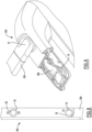
- each rail main portion 18a and 18b is its generally L-shaped construction, when viewed in cross section, as shown in Figure 5 . This feature will be discussed in greater detail in the following paragraphs.
- the L-shaped cross-sectional construction enables each of the cross bar assemblies 24a and 24b to rest within the L-shaped configuration of their associated support rails 12a and 12b, respectively, and be completely hidden from view, or virtually completely hidden from view, when a person stands along the driver's side or the passenger side of the vehicle 16 and looks at the system 10.
- cross bar assembly 24a and 24b are both compactly housed on their respective main rail portions 18a and 18b when mounted in their stowed positions. And even as shown in Figure 4 , when viewing the inside of the support rail assembly 12b, the cross bar assembly 24b has the general appearance of being an integrally formed portion of the support rail assembly 12b.
- the L-shaped cross-sectional construction of the main rail portion 18b can be seen.
- the main rail portion 18a has this same cross-sectional shape, and will appear as a mirror image of the main rail portion 18b when the two support rail assemblies 12a and 12b are installed on the vehicle outer body roof surface 14.
- the rail main portion 18b has a horizontal shelf portion 18' and a vertical wall portion 18".
- the vertical wall portion 18" is about equal (i.e., level with) the upper surface of the cross bar assembly 24b, as indicated by arrow "H"
- the horizontal shelf portion 18' is about equal in length to a cross-sectional width of the cross bar assembly 24b, as indicated by arrow "L".
- the cross bar assembly 24b can be generally concealed from view when standing along the passenger side of the vehicle 16 because it does not extend above the upper edge of the vertical wall portion 18". Nor does the cross bar assembly 24 extend beyond an inward edge of the horizontal shelf portion 18' when mounted in its stowed position. This further helps to provide a clean, aesthetically pleasing appearance to the rack system 10 when it is viewed from the front or rear while the cross bar assemblies 24a and 24b are both mounted in their stowed positions.
- Still another advantage is that the horizontal shelf portions 18' of the support rail assemblies 12a and 12b lie within a common horizontal plane, which enables both of the cross bar assemblies 24a and 24b be positioned level when they are in their operative positions (assuming the vehicle 16 is on level ground), and both to be positioned at the same vertical height when positioned in their stowed positions on their respective support rail assembly 12a or 12b. This further helps to create a highly aesthetically pleasing appearance whether the cross bar assemblies 24a and 24b are secured in their operative or stowed positions.
- the ability to stow the cross bar assemblies 24a and 24b on their respective main rail portions 18a and 18b, respectively, without the cross bar assemblies projecting above the main rail portions 18, or inwardly beyond the inner edges of the main rail portions 18a and 18b, also helps to significantly reduce the aerodynamic drag imposed by the system 10 while the vehicle 16 is travelling at intermediate or highway speeds, and potentially helps to eliminate, or substantially reduce, any wind noise that might be encountered when the vehicle is operated with the cross bar assemblies 24a and 24b mounted in their stowed positions.
- the stowed cross bars 24a and 24b appear to be integral portions of the main support rail assemblies 12a and 12b when mounted in their stowed positions, and thus make for a very aesthetically clean looking and highly aerodynamic configuration.
- the support rail assembly 12a of Figure 6 includes the main rail portion 18a which telescopically engages with structural mounting portions 26a and 28a of the front and rear support foot assemblies 22a and 22b, respectively.
- the front and rear structural mounting portions 26a and 28a may be of aluminum die cast construction or otherwise made from similarly robust construction techniques and materials (e.g., high strength plastics).
- the structural mounting portions 26a and 28a are attached to the outer body roof surface 14 of the vehicle 16 and telescopically receive the opposing ends of the main rail portion 18a.
- a front lower cover element 30a and a rear lower cover element 32a (e.g., both made from plastic), as well as front and rear mounting pads 34a and 36a, are interposed between the structural mounting portions and the outer body roof surface 14.
- Conventional threaded fasteners (or a combination of threaded fasteners and suitable adhesives) may be used to secure the structural mounting portions 26a and 28a to the outer body roof surface 14.
- Decorative front and rear cover portions 38a and 40a may also be secured over the front and rear structural mounting portions 26a and 28a, respectively.
- a center support assembly comprised of components structural mounting portions 46a, 48a and 50a may be interconnected using conventional threaded fasteners to secure a midpoint of the main rail portion 18a to the vehicle outer body roof surface 14 to provide added support and rigidity to the main rail portion 18a.
- the cross bar assembly 24a includes a first end having a pivot assembly 52 and a second end having a manually actuatable latching assembly 54.
- the pivot assembly 52 is coupled to a mounting surface 56 on the front structural mounting portion 28a.
- the latching assembly 54 may be engaged with an opening 58 in the main rail portion 18a to hold the cross bar assembly 24a in the stowed position on the main rail portion 18a, when not in use.
- the latching assembly 54 passes through an opening 60 ( Figure 7 ) in the main rail portion 18b and into engagement with a portion of a front structural mounting portion 26b of the support rail assembly 12b. This places the front cross bar assembly 24a in its operative position extending perpendicularly between the two support rail assemblies 12a and 12b.
- the support rail assembly 12b is similar in construction to the support rail assembly 12a, and components in common will be designated with the same reference number used to describe the support rail assembly 12a but with a "b" suffix.
- the support rail assembly 12a further includes a mounting element 62 fixedly secured by conventional threaded fasteners within the main rail portion 18a, and accessible through an opening 76 formed in the main rail portion.
- the main rail portion 18b includes a channel 64 formed along a portion of its length, and generally in the rear half of the length thereof. The channel 64 is also shown in Figure 10 .
- a slidable securing element in this example a slide block 66, with an associated elastomeric O-ring 67 and a threaded fastener plate 68, are all positioned inside the main rail portion 18b, and coupled to a pivot assembly 70 associated with a first (i.e., pivoting) end of the rear cross bar assembly 24b, which enables pivoting of the rear cross bar assembly 24b between the stowed position, wherein it is arranged parallel to the main rail portion 18b, and its operative position wherein it extends perpendicularly between the rear support foot assemblies 22a and 22b.
- the pivot assembly 70 may each be constructed in accordance with the teachings of one or more of the above referenced U.S. Patents, which enables a small degree of pivotal motion within a vertical plane, as well as the needed pivoting motion within a horizontal plane, to enable lifting the cross bar 24a or 24b vertically a small degree while repositioning the cross bar assembly 24a or 24b to one or the other of the support rail assemblies 12a or 12b.
- the O-ring 67 provides the beneficial feature of providing a small degree of resilience in the attachment of the cross bar 24a or 24b which allows its associated cross bar to be lifted vertically a small amount, while still permitting pivoting motion in the horizontal plane, and while still enabling a sufficiently secure attachment of the pivoting end of each cross bar assembly to prevent any rattling during use of the vehicle 16.
- the opposite end of the rear cross bar assembly 24b includes a user engageable latching assembly 72 which may be identical in construction to the latching assembly 54.
- the rear cross bar assembly 24b has three possible mounting positions, one being a stowed position on its associated main rail portion 18b, a second being a rearward most operative position, and the third being an intermediate position closer to the front of the vehicle 16. These two rearward mounting positions are shown in Figure 2 , with it being understood one or the other, but not both, will be used at any given time. This provides significant added flexibility in carrying articles of widely varying dimensions.
- the pivot assembly 70 can be secured at either extreme end of the channel 64, to thus help hold the rear cross bar assembly 24b in any one of the above three described positions, by simply tightening a threaded element 71 ( Figure 7 ) that extends therethrough and engages the threaded fastener plate 68.
- latching assemblies 54 and 72 are well known in the art. These types of user engageable latching assemblies, for example, are disclosed in US 6,811,066 B1 and US 7,066,364 B1 , assigned to the assignee of the present disclosure. Suitable pivot assemblies for use with a cross bar are also disclosed in these patents. Furthermore, it will be appreciated that the various components shown in Figure 7 and denoted with reference numbers having the suffix "b" are the counterparts to those described above and shown in Figure 6 .
- FIG 8 a plan view of a rear portion of the main rail portion 18a is shown with the mounting element 62 fixedly secured within the main rail portion.
- the rear structural mounting portion 28a includes an integrally secured mounting element 74, as also shown in Figure 9 , which is inserted within the main rail portion 18a when the rear structural mounting portion 28a is assembled to the main rail portion 18a during assembly of the support rail assembly 12a.
- the main rail portion 18a includes the generally circular opening 76 and an additional generally circular opening 78, which each expose their respective mounting elements 62 and 74. This enables the latching assembly 54 of the rear cross bar assembly 24b to engage either one of the mounting elements 62 or 74, depending on which of the two rearward locations it is being mounted at. And as noted above, the latching assembly 54 of the front cross bar assembly 24a engages the mounting element 74 when it is positioned in its stowed position on the support rail assembly 12a.
- the channel 64 in the main rail portion 18b forms a track which can be seen better along with the slide block 66 positioned therein.
- the slide block 66 is shown in both of its potential rearward mounting positions, although it will be appreciated that in actual use of the system 10 there is only one slide block 66 being used.
- the slide block 66 is held at a specific position by tightening of the threaded external fastener element 71 to the fastener plate 68.
- This construction secures the pivot assembly 70 to the main rail portion 18b while still allowing both pivoting motion of the rear cross bar assembly 24b, as well as linear sliding movement of the pivot assembly 70, at one end of the rear cross bar assembly 24b.
- the rear cross bar assembly 24b' in Figure 11 has a pivot assembly 70' construction which incorporates a threaded element 71' which extends therethrough and which engages a suitable threaded plate or element (not shown in Figure 11 ) fixedly mounted within the support rail assembly 12b'.
- a suitable threaded plate or element (not shown in Figure 11 ) fixedly mounted within the support rail assembly 12b'.
- manual removal of the threaded element 71' enables the pivot assembly 70' to be completely lifted off of its associated support rail assembly 12b' and moved to a more forward position on the support rail assembly 12b' and then re-secured thereto using the same threaded element 71'.
- This configuration also allows the rear cross bar 24b' to be pivoted into its operative position, when mounted as shown in Figure 11 , by simply rotating the cross bar assembly 24b' perpendicularly until the opposite end is positioned over the other support rail assembly 12a.
- Figure 11 shows another feature that may be incorporated into the system 10 which prevents the rear cross bar assembly 24b' from falling on the outer body roof surface 14 if the user accidentally loses his/her grip on the assembly 24b' while moving the rear cross bar assembly from its stowed position into its operative position, or from its operative position into its stowed position.
- a rear support foot 22b' includes a circumferential ramp portion 84' projecting up from an upper surface 86' thereof.
- the ramp portion 84' cooperates with the lower surface 82' by contacting the lower surface 82' to prevent the cross bar assembly 24b' from dropping down onto the outer body roof surface 14 of the vehicle 16 if the user should accidentally release the cross bar assembly 24b' before the latching assembly 72 at its opposite end is positioned over the support rail assembly 12a. In such an instance, the latching assembly 72 will be held above the outer body roof surface 14 by contact with the ramp portion 84'.
- This feature also enables shorter individuals who may not be able to maneuver the cross bar assembly 24b easily into its fully perpendicular extending position to initiate the process from one side of the vehicle 16 by moving the rear cross bar assembly to an intermediate position over the outer body roof surface 14, and then going to the other side of the vehicle to reach up and pull the opposite end of the rear cross bar assembly 24b into its fully perpendicular position for attachment to the support rail assembly 12a. It will be appreciated that this feature may be incorporated into the front support foot 20a as well if desired.
- the front cross bar assembly 104a has a first end with a pivot assembly 106a which provides for pivotal movement of the cross bar assembly 104a between it stowed position and its operative position, while the opposite end includes a latching assembly 108a which allows the front cross bar assembly to be secured in its operative position, or as well as in its stowed position.
- the rear cross bar assembly 104b similarly includes a pivot assembly 108b located at its rear end, and a latching assembly 106a located at its front end, enabling the rear cross bar assembly to be pivoted and secured in either one of two different operative positions near a rear area of the support rail assemblies 102a and 102b.
- the rear cross bar assembly 104b is fully removable to enable the rearward mounting at two different positions, as described above with respect to Figure 10 .
- the system 100 provides the same benefits as the system 10 in that the cross bar assemblies 104a and 104b are hidden from view when placed in their stowed positions, and when an individual is viewing the vehicle 16 from most angles around the perimeter of the vehicle.
- FIG. 13 an exploded perspective view of the components of the support rail assembly 102b are shown to illustrate the dramatically reduced number of individual component parts which make up its construction.
- the support rail assembly 102a may be of nearly identical construction, with the principal differences being the positioning of the components which engage with the latching assemblies 108a to enable the cross bar assemblies 104a and 104b to be placed in their stowed and operative positions.
- the main rail portion 110b has a central portion 112b having the L-shaped cross-sectional construction described herein for the support rail assemblies 12a and 12b, but also includes an integrally formed curving front, portion 114b at one end, and an integrally formed curving rear portion 116b at its other end.
- a front structural mounting block 118 e.g., die-cast aluminum or steel
- threaded fasteners is secured to the curving front portion 114b of the main rail portion 110b and to a decorative lower/outer cover member 120 by using threaded fasteners 122.
- the decorative lower/outer cover has a shape and profile to fit under the curving front portion 114b of the main rail portion 110b.
- a separate plurality of threaded screws 124 is used to secure a decorative upper cover member 126 to the lower/outer cover member 120 such that the curving front portion 114b is partially encapsulated between the two decorative cover members 120 and 126.
- a resilient pad 128 is placed directly against the outer body roof surface 14, and lower areas of the two decorative cover members 120 and 126 rest against the pad 128, which serves to take up any gaps between the decorative cover members 120/126 and the outer body roof surface 14.
- a similar construction is present at the curving rear portion 116b of the main rail portion 110b, where a structural mounting block 130 with integrated threaded fasteners is secured to the curving rear portion 116b, and to a decorative rear lower cover member 132, via threaded fasteners 134.
- a decorative rear upper/inner cover member 136 is secured to the decorative rear lower cover member 132 via a separate plurality of threaded fasteners 138, which partially encapsulates the rear portion 116b of the main rail portion 110b.
- a resilient pad 140 is placed between the outer body roof surface 14 and the decorative rear cover members 132/136 to help take up any gaps between these components and the outer body roof surface.
- This configuration enables the curving front and rear portions 114b and 116b of the main rail portion 110b to be directly secured to the vehicle outer body surface 14, which allows forces experienced by the main rail portion 110b to be transferred directly into the outer body surface 14 rather than into an intermediate component.
- This construction not only significantly enhances the strength of the main rail portion 110b, but also significantly enhances its overall rigidity as well.
- the reduced number of independent component parts also reduces costs and enables even quicker and easier assembly of the support rail assembly 102b on the vehicle 16.
- a front cross bar mounting element 142 is fixedly secured with threaded fasteners 144 to the main rail portion, which provides the point of attachment for the latching assembly 108a of the front cross bar assembly 104a when the front cross bar assembly is secured in its operative position.
- a pair of rear cross bar mounting elements 146 and 148 are secured to the main rail portion 110b via pairs of threaded fasteners 150 and 152, respectively.
- the rear cross bar mounting elements 146 and 148 define the two operative positions for the rear cross bar assembly 104b, while the rearward most cross bar mounting element 146 also operates to provide an attachment point for the rear cross bar assembly 104b when it is secured in its stowed position over the support rail assembly 102b.
- first, second, third, etc. may be used herein to describe various elements, components, regions, layers and/or sections, these elements, components, regions, layers and/or sections should not be limited by these terms. These terms may be only used to distinguish one element, component, region, layer or section from another region, layer or section. Terms such as “first,” “second,” and other numerical terms when used herein do not imply a sequence or order unless clearly indicated by the context. Thus, a first element, component, region, layer or section discussed below could be termed a second element, component, region, layer or section without departing from the teachings of the examples and embodiments.
- spatially relative terms such as “inner,” “outer,” “beneath,” “below,” “lower,” “above,” “upper,” and the like, may be used herein for ease of description to describe one element or feature's relationship to another element(s) or feature(s) as illustrated in the figures.
- Spatially relative terms may be intended to encompass different orientations of the device in use or operation in addition to the orientation depicted in the figures. For example, if the device in the figures is turned over, elements described as “below” or “beneath” other elements or features would then be oriented “above” the other elements or features.
- the example term “below” can encompass both an orientation of above and below.
- the device may be otherwise oriented (rotated 90 degrees or at other orientations) and the spatially relative descriptors used herein interpreted accordingly.
Landscapes
- Engineering & Computer Science (AREA)
- Mechanical Engineering (AREA)
- Fittings On The Vehicle Exterior For Carrying Loads, And Devices For Holding Or Mounting Articles (AREA)
Claims (12)
- Gegenstandsträgersystem (100) für ein Fahrzeug zum Transportieren von Gegenständen in der Höhe über einer äußeren Karosseriefläche eines Fahrzeugs, wobei das System aufweist:eine erste und eine zweite Stützschienenbaugruppe (102a, 102b), die an einer äußere Karosseriedachfläche (14) parallel zueinander in einer fixierbaren Weise abstützbar sind, wobei die erste Stützschienenbaugruppe (102a) neben einer ersten Seite des Fahrzeugs (16) sicherbar ist, und wobei die zweite Stützschienenanordnung (102b) neben einer zweiten Seite des Fahrzeugs (16) sicherbar ist;eine erste Querstange (104a), die konfiguriert ist, um in einer verstauten Position an der ersten Stützschienenbaugruppe (102a) und in einer Betriebsposition, die sich senkrecht zwischen der ersten und zweiten Stützschienenbaugruppe (102a, 102b) erstreckt, gesichert zu werden und um an der erste und zweite Stützschienenbaugruppe (102a, 102b) gesichert zu werden, wobei ein erstes Ende der ersten Querstange (104a) schwenkbar an der ersten Stützschienenbaugruppe (102a) gesichert ist, und ein zweites Ende der ersten Querstangenbaugruppe (104a) eine erste Verriegelungsbaugruppe (108a) zum Eingreifen in die zweite Stützschienenbaugruppe (102b) aufweist, um die erste Querstange (104a) in der Betriebsposition zu halten;eine zweite Querstange (104b), die konfiguriert ist, um in einer verstauten Position an der zweite Stützschienenbaugruppe (102b) und in einer Betriebsposition, die sich senkrecht zwischen der ersten und zweiten Stützschienenbaugruppe (102a, 102b) erstreckt, gesichert zu werden, und um an der ersten und zweiten Stützschienenbaugruppe (102a, 102b) gesichert zu werden, wobei ein erstes Ende der zweiten Querstange (104b) schwenkbar an der zweiten Stützschienenbaugruppe (102b) gesichert ist, und ein zweites Ende der zweiten Querstangenbaugruppe (104b) eine zweite Verriegelungsbaugruppe (108b) zum Eingreifen in die erste Stützschienenbaugruppe (102a) aufweist, um die zweite Querstange (104b) in der Betriebsposition zu sichern;Jede von der ersten und zweiten Stützschienenbaugruppe (102a, 102b) weist auf:einen Hauptschienenteil (110a, 110b), der vom Ende her gesehen eine L-Form hat;wobei die L-Form einen vertikalen Wandabschnitt (18") und ein horizontales Ablageteil (18') hat; undwobei der vertikale Wandabschnitt (18") eine Höhe hat, die ausreicht, um sich mindestens bis zu einer oberen Fläche der zugehörigen ersten oder zweiten Querstange zu erstrecken, wenn seine zugehörige erste oder zweite Querstange (104a, 104b) in der verstauten Position positioniert ist, um so die erste oder zweite Querstange (104a, 104b) zu verstecken; undwobei die erste Querstange (104a), wenn sie in der verstauten Position ist, nicht sichtbar ist, wenn die ersten Stützschienenbaugruppe (102a) von der ersten Seite des Fahrzeugs (16) aus betrachtet wird, und die zweite Querstange (104b) nicht sichtbar ist, wenn sie in der verstauten Position ist, wenn die zweiten Stützschienenbaugruppe (102b) von der zweiten Seite des Fahrzeugs (16) aus betrachten wird;dadurch gekennzeichnet, dassjede von der ersten oder zweiten Stützschienenbaugruppe (102a, 102b) einen einzigen, streckgeformten Hauptschienenabschnitt (110b) aufweist, der aus mindestens einem von Aluminium oder Stahl geformt ist, und einem integral geformten Mittelteil (112b) hat, welcher die L-geformte Querschnittskonstruktion hat und das integral geformte, gekrümmte vordere und hintere, vergrößertes Endteil (114b, 116b) hat, und wobei die vergrößerten Endteile (114b, 116b) konfiguriert sind, um über externe Befestigungselemente an der äußeren Karosseriedachfläche (14) des Fahrzeugs (16) gesichert zu werden, undwobei ein struktureller Montageblock (118, 130) mit integrierten Gewindebefestigungen jeweils an jedem von dem gekrümmten vorderen und hinteren Teil (114b, 116b) des Hauptschienenteils (110b) und an einem dekorativen unteren Abdeckelement (120, 132) gesichert ist, wobei das jeweilige dekorative untere Abdeckelement (120, 132) eine Form und ein Profil aufweist, um unter den jeweiligen gekrümmten vorderen oder hinteren Teil (114b, 116b) zu passen, und ein jeweiliges dekoratives oberes Abdeckelement (126, 136) am jeweiligen unteren Abdeckelement (120, 132) gesichert ist, so dass der jeweilige gekrümmte vordere oder hintere Teil (114b, 116b) teilweise zwischen den jeweiligen beiden dekorativen Abdeckelementen (120, 126; 132, 136) eingekapselt ist.
- System (100) des Anspruchs 1, wobei das horizontale Ablageteil (18') von jeweils einer von der ersten oder der zweiten Stützschienenbaugruppe (102a, 102b) senkrecht von dem vertikalen Wandteil (18") erstreckt,
wobei entweder die erste oder zweite Querstange (104a, 104b) über jeweils einem der horizontalen Ablageteile (18') positioniert ist, wenn es in seiner verstauten Position angeordnet ist. - System (100) des Anspruchs 2, wobei eine Abmessung des horizontalen Ablageteils (18') der ersten Stützschienenbaugruppe (102a) gleich einer Breite der ersten Querstange (104a) ist, und eine Abmessung des horizontalen Ablageteils (18') der zweiten Stützschienenbaugruppe (102b) gleich der Breite der zweiten Querstange (104b) ist.
- System (100) des Anspruchs 1, wobei das erste Ende von der zweite Querstangenbaugruppe (104b) verschiebbar entlang eines Teils der zweiten Stützschienenbaugruppe (102b) beweglich ist, um mindestens eine erste und eine zweite separate Betriebsposition für die zweite Querstange (104b) zu definieren.
- Das System (100) des Anspruchs 4, wobei:die zweite Stützschienenbaugruppe (102b) einen verlängerten, linearen Schlitz aufweist und ein Gleitblock (66) damit im Eingriff ist; unddas erste Ende der zweiten Querstange (104b) im Eingriff mit dem Gleitblock (66) ist, um eine Bewegung des ersten Endes der zweiten Querstange (104b) entlang des verlängerten, linearen Schlitzes zu erlauben.
- System (100) des Anspruchs 5, wobei der verlängerte, lineare Schlitz zwei voneinander beabstandete Befestigungsstellen zum Befestigen des ersten Endes von der zweiten Querstange (104b) definiert.
- System (100) des Anspruchs 1, wobei ein erstes Ende von der zweiten Querstange (104b) ein Befestigungselement aufweist, um das Lösen des ersten Endes von der zweiten Querstange (104b) an einer ersten Montagestelle an der zweiten Stützschienenbaugruppe (102b) zu ermöglichen, und ein erneutes Anbringen des ersten Endes der zweiten Querstange (104b) an einer zweiten Befestigungsstelle auf der zweiten Stützschienenbaugruppe (102b) zu ermöglichen, die von dem ersten Montageort beabstandet ist.
- System (100) des Anspruchs 1, wobei:die zweite Stützschienenbaugruppe (102b) einen Stützfuß (22b') aufweist, undwobei der Stützfuß (22b') einen erhöhten Rampenteil (84') aufweist, der mit einem ersten Ende der zweiten Querstange (24b') zusammenwirkt, um ein zweites Ende von der zweite Querstange (24b') zu hindern, dass es die äußere Karosseriedachfläche (14) des Fahrzeugs (16) berührt, wenn die zweite Querstange (24b') entriegelt wird und das zweite Ende zwischen der ersten und zweiten Stützschienenbaugruppen (102a, 102b) positioniert wird.
- System (100) des Anspruchs 1, wobei der horizontale Ablageteil (18') von der erste und zweite Stützschienenbaugruppe (102a, 102b) darüber hinaus angeordnet sind, um sich senkrecht gegenseitig in einer gemeinsamen horizontalen Ebene zu erstrecken.
- System (100) des Anspruchs 1, wobei das horizontale Ablageteil (18') von der ersten Stützschienenbaugruppe (102a) eine Längendimension hat, die ausreicht, um vollständig unter die erste Querstange (104a) sich zu erstrecken, wenn die erste Querstange (104a) in der verstauten Position auf der ersten Stützschienenbaugruppe (102a) platziert wird.
- System (100) des Anspruchs 9, wobei der horizontale Ablageteil (18') von der zweiten Stützschienenbaugruppe (102b) eine Länge hat, die ausreicht, um sich vollständig unter der zweiten Querstange (104b) zu erstrecken, wenn die zweite Querstange (104b) in der verstauten Position auf der zweiten Stützschienenbaugruppe (102b) platziert wird.
- System (100) des Anspruchs 1,wobei das erste Ende von der ersten Querstange (104a) schwenkbar an der ersten Stützschienenbaugruppe (102a) durch eine erste Schwenkbaugruppe (106a) gesichert ist;wobei das erste Ende von der zweiten Querstange (104b) schwenkbar an der zweiten Stützschienenbaugruppe (102b) durch eine zweite Schwenkbaugruppe (108b) gesichert ist; undwobei die erste und/oder zweite Schwenkbaugruppe (106a; 108b) ein Gewindeelement (71') enthält, welches sich dadurch erstreckt und welches in eine geeignete Gewindeplatte oder -element eingreift, die oder das fest innerhalb der Stützschienenbaugruppe (102a; 102b) montiert ist, so dass das manuelles Entfernen des Gewindeelements (71') der Schwenkbaugruppe (70') ermöglicht, vollständig von der zugehörigen Stützschienenbaugruppe (102a; 102b) abgehoben zu werden und an eine andere Position auf der Tragschienenbaugruppe (102a; 102b) verschoben zu werden und dann durch Gebrauch desselben Gewindeelement (71') daran gesichert zu werden.
Applications Claiming Priority (1)
| Application Number | Priority Date | Filing Date | Title |
|---|---|---|---|
| US17/453,581 US11912240B2 (en) | 2021-11-04 | 2021-11-04 | Vehicle article carrier rack system with stowable, concealable cross bars |
Publications (2)
| Publication Number | Publication Date |
|---|---|
| EP4177112A1 EP4177112A1 (de) | 2023-05-10 |
| EP4177112B1 true EP4177112B1 (de) | 2025-04-30 |
Family
ID=82742617
Family Applications (1)
| Application Number | Title | Priority Date | Filing Date |
|---|---|---|---|
| EP22186985.2A Active EP4177112B1 (de) | 2021-11-04 | 2022-07-26 | Gepäckträgersystem für fahrzeuge mit verstaubaren, verdeckbaren querträgern |
Country Status (2)
| Country | Link |
|---|---|
| US (1) | US11912240B2 (de) |
| EP (1) | EP4177112B1 (de) |
Families Citing this family (1)
| Publication number | Priority date | Publication date | Assignee | Title |
|---|---|---|---|---|
| EP3936387A1 (de) * | 2020-07-10 | 2022-01-12 | Ningbo Geely Automobile Research & Development Co. Ltd. | Dachschienensystem zum anordnen auf dem dach eines fahrzeugs und verfahren zum montieren des dachschienensystems |
Citations (2)
| Publication number | Priority date | Publication date | Assignee | Title |
|---|---|---|---|---|
| US5715981A (en) * | 1993-10-18 | 1998-02-10 | Erbsloh Ag | Rails for car roofs |
| US7090103B2 (en) * | 2002-10-24 | 2006-08-15 | Jac Products, Inc. | Vehicle article carrier having stowable cross bars |
Family Cites Families (46)
| Publication number | Priority date | Publication date | Assignee | Title |
|---|---|---|---|---|
| US5069377A (en) * | 1990-12-10 | 1991-12-03 | Alton Baughman | Roof rack for vehicles |
| US5393114A (en) | 1991-09-19 | 1995-02-28 | Christensen; David | Reversible utility rail and utility rack |
| DE4321535A1 (de) | 1993-06-29 | 1995-01-12 | Happich Gmbh Gebr | Dachlastenträger für Fahrzeuge |
| DE4321537A1 (de) * | 1993-06-29 | 1995-01-12 | Happich Gmbh Gebr | Dachreling für Fahrzeuge |
| DE4323098A1 (de) * | 1993-07-10 | 1995-01-12 | Happich Gmbh Gebr | Dachreling für Fahrzeuge |
| US5494327A (en) | 1995-01-31 | 1996-02-27 | Tracrac, Inc. | Sliding connection for releasably and adjustably attaching an overhead rack to a pickup truck |
| US6286739B1 (en) | 1999-09-29 | 2001-09-11 | Sportrack Llc | Article carrier with stowing crossrails |
| JP3560515B2 (ja) * | 1999-09-30 | 2004-09-02 | ジー・ピー・ダイキョー株式会社 | 車両用ルーフラック |
| US6431634B1 (en) | 2001-01-16 | 2002-08-13 | Frederick Ananian | Collapsible truck shell assembly and accessories |
| CA2358377A1 (en) | 2001-10-10 | 2003-04-10 | Donald Martin | Truck carrier |
| US6811066B2 (en) | 2001-10-26 | 2004-11-02 | Jac Products Inc. | Vehicle article carrier having stowable cross bars |
| US7066364B2 (en) | 2002-10-24 | 2006-06-27 | Jac Products, Inc. | Vehicle article carrier having stowable cross bars |
| US20040134953A1 (en) | 2003-01-09 | 2004-07-15 | Perez Carlos Valadez | Multi positionable rack for a pick up truck bed |
| FR2854112B1 (fr) | 2003-04-23 | 2006-07-14 | Peugeot Citroen Automobiles Sa | Ensemble de barres de toit pour un vehicule automobile |
| US20050023314A1 (en) | 2003-07-30 | 2005-02-03 | Ford Motor Company | Telescoping roof rack assembly for a vehicle having a truck bed |
| US7296836B1 (en) | 2004-06-07 | 2007-11-20 | Zeljko Sabo | Truck rack apparatus |
| DE102005018158A1 (de) * | 2004-09-24 | 2006-04-06 | Hans und Ottmar Binder GmbH Oberflächenveredelung | Dachträgersystem für ein Fahrzeug sowie Verfahren zur Herstellung des Dachträgersystems und Fahrzeug mit einem Dachträgersystem |
| EP1945480A1 (de) | 2005-10-21 | 2008-07-23 | Connaught Construction Company | Anhebbare abdeckung für die ladefläche eines lastwagens |
| US7296837B2 (en) | 2005-10-31 | 2007-11-20 | Thule Sweden A.B. | Load carrier arrangement for a vehicle bed comprising an internal bed rail system |
| US8028875B2 (en) | 2006-10-26 | 2011-10-04 | Jac Products, Inc. | Vehicle article carrier having swing in place cross bars |
| US20080100075A1 (en) | 2006-10-31 | 2008-05-01 | Derecktor Thomas E | Sliding overhead rack for pickup trucks |
| US7464977B1 (en) | 2007-03-16 | 2008-12-16 | Price Brent A | Elevating long cargo support assembly for pickup truck |
| US8276794B2 (en) | 2007-06-13 | 2012-10-02 | Jac Products, Inc. | Vehicle article carrier having releasable and stowable cross bars |
| US8251267B2 (en) | 2007-06-13 | 2012-08-28 | Jac Products, Inc. | Vehicle article carrier having single sided releasable and stowable cross bars |
| US8485403B2 (en) * | 2008-03-27 | 2013-07-16 | GM Global Technology Operations LLC | Roof rack assembly with stowable cross members |
| CA2670173C (en) * | 2008-06-27 | 2016-11-29 | Magna International Inc. | Roof rack with stowable non-adjustable crossbars |
| US20100072237A1 (en) | 2008-09-25 | 2010-03-25 | Christopher Phillip Green | Disassemblable Rack Having Dual Mounting Crossbars for Use with Pickup Trucks and SUVs |
| US8235264B2 (en) | 2008-10-01 | 2012-08-07 | Jac Products, Inc. | System and method for vehicle article carrier having stowable cross bars |
| US8096454B2 (en) | 2008-10-01 | 2012-01-17 | Jac Products, Inc. | System and method for vehicle article carrier having stowable cross bars |
| US8528799B2 (en) | 2008-10-01 | 2013-09-10 | Jac Products, Inc. | System and method for vehicle article carrier having stowable cross bars |
| FR2939386B1 (fr) | 2008-12-05 | 2012-01-13 | Peugeot Citroen Automobiles Sa | Ensemble de barres de toit pour vehicule automobile. |
| US9981612B2 (en) | 2009-05-18 | 2018-05-29 | Thule Inc. | Modular rack system with gussetless joints |
| US8376684B2 (en) | 2010-04-12 | 2013-02-19 | Pedro A. Juarez-Ortega | Loader and carrier apparatus |
| US9150161B2 (en) | 2012-07-31 | 2015-10-06 | Thule Sweden Ab | Vehicular load carrier rack with locking cover |
| US9725046B2 (en) | 2012-07-31 | 2017-08-08 | Thule Sweden Ab | Demarcated height adjustable load carrier rack |
| AU2013301209B2 (en) | 2012-08-07 | 2017-08-24 | Jack FINESTONE | A load carrying assembly |
| US9352696B2 (en) * | 2013-11-11 | 2016-05-31 | Honda Motor Co., Ltd. | Low profile roof rail |
| US9132784B2 (en) | 2014-01-13 | 2015-09-15 | Daws Manufacturing Company, Inc. | Truck headache rack |
| CA2885043A1 (en) | 2014-03-13 | 2015-09-13 | Winston Breeden | Folding ladder rack |
| US10059274B2 (en) | 2015-02-23 | 2018-08-28 | Jac Products, Inc. | System and method for vehicle article carrier having stowable cross bars |
| US10071692B2 (en) | 2015-03-30 | 2018-09-11 | Jac Products, Inc. | Pickup truck roof rack system |
| IT201700114809A1 (it) * | 2017-10-12 | 2019-04-12 | ATHANOR Srl | Dispositivo connettibile al portabagagli di un’autovettura per un rapido approntamento dello stesso al trasporto in sicurezza di uno o più colli, portabagagli comprendente detto dispositivo e autovettura dotata di un portabagagli comprendente detto dispositivo |
| AU2019203756A1 (en) | 2018-06-01 | 2019-12-19 | Yakima Australia Pty Limited | Truck-Mountable Cargo Rack |
| US10850675B2 (en) * | 2018-08-20 | 2020-12-01 | Dura Operating, Llc | Stowable roof rack for a vehicle |
| CN210310582U (zh) | 2019-06-28 | 2020-04-14 | 浙江阜康机械有限公司 | 简易车用货架 |
| US11052828B2 (en) | 2019-09-19 | 2021-07-06 | George Huisman | Cargo rack for trucks |
-
2021
- 2021-11-04 US US17/453,581 patent/US11912240B2/en active Active
-
2022
- 2022-07-26 EP EP22186985.2A patent/EP4177112B1/de active Active
Patent Citations (2)
| Publication number | Priority date | Publication date | Assignee | Title |
|---|---|---|---|---|
| US5715981A (en) * | 1993-10-18 | 1998-02-10 | Erbsloh Ag | Rails for car roofs |
| US7090103B2 (en) * | 2002-10-24 | 2006-08-15 | Jac Products, Inc. | Vehicle article carrier having stowable cross bars |
Also Published As
| Publication number | Publication date |
|---|---|
| US20230135957A1 (en) | 2023-05-04 |
| EP4177112A1 (de) | 2023-05-10 |
| US11912240B2 (en) | 2024-02-27 |
Similar Documents
| Publication | Publication Date | Title |
|---|---|---|
| US11027660B2 (en) | Vehicle article carrier system having swing-in-place cross bars | |
| EP0495020B1 (de) | Vorrichtung zur verbindung eines schwenkbaren querbalkens mit einem stützelement | |
| US8276794B2 (en) | Vehicle article carrier having releasable and stowable cross bars | |
| US6415970B1 (en) | Vehicle article carrier with supports configurable elevated siderails or flush mounted slats | |
| US8096454B2 (en) | System and method for vehicle article carrier having stowable cross bars | |
| US6840417B2 (en) | Motorcycle trunk and motorcycle with attached motorcycle trunk | |
| US5975618A (en) | Vehicle tonneau cover clamp | |
| US8251267B2 (en) | Vehicle article carrier having single sided releasable and stowable cross bars | |
| JPH06305366A (ja) | 車両用のルーフキャリヤ | |
| US4899917A (en) | Vehicle article carrier | |
| EP0437514A1 (de) | Gepäckträger für fahrzeuge. | |
| CA2391041A1 (en) | Vehicle article carrier having telescopically extendable article carrier portion | |
| EP4177112A1 (de) | Gepäckträgersystem für fahrzeuge mit verstaubaren, verdeckbaren querträgern | |
| US5947355A (en) | Vehicle article carrier | |
| US20050082324A1 (en) | Article carrier and bicycle rack system | |
| US20060273123A1 (en) | Rack tower assemblies and rack systems | |
| US7494032B2 (en) | Sliding bed accessory arrangement | |
| US10723272B2 (en) | Step rail system for vehicle | |
| EP2210778B1 (de) | Gepäckbehälter für ein Kraftfahrzeug | |
| CN114906059B (zh) | 内置娱乐设备支架 | |
| GB2308110A (en) | Vehicle article carrier | |
| CA1314269C (en) | Vehicle deck rack and wind deflector with integral pop-up tie-downs | |
| EP1858729B1 (de) | System zur montage von nutzfahrzeugkabinenzubehör | |
| FR2793744B1 (fr) | Moyen de verrouillage du haut d'un dossier de siege arriere reglable en position longitudinale dans un habitacle de vehicule automobile | |
| MXPA01001865A (en) | Cargo net assembly |
Legal Events
| Date | Code | Title | Description |
|---|---|---|---|
| PUAI | Public reference made under article 153(3) epc to a published international application that has entered the european phase |
Free format text: ORIGINAL CODE: 0009012 |
|
| STAA | Information on the status of an ep patent application or granted ep patent |
Free format text: STATUS: REQUEST FOR EXAMINATION WAS MADE |
|
| 17P | Request for examination filed |
Effective date: 20220801 |
|
| AK | Designated contracting states |
Kind code of ref document: A1 Designated state(s): AL AT BE BG CH CY CZ DE DK EE ES FI FR GB GR HR HU IE IS IT LI LT LU LV MC MK MT NL NO PL PT RO RS SE SI SK SM TR |
|
| STAA | Information on the status of an ep patent application or granted ep patent |
Free format text: STATUS: EXAMINATION IS IN PROGRESS |
|
| RBV | Designated contracting states (corrected) |
Designated state(s): AL AT BE BG CH CY CZ DE DK EE ES FI FR GB GR HR HU IE IS IT LI LT LU LV MC MK MT NL NO PL PT RO RS SE SI SK SM TR |
|
| 17Q | First examination report despatched |
Effective date: 20231204 |
|
| GRAP | Despatch of communication of intention to grant a patent |
Free format text: ORIGINAL CODE: EPIDOSNIGR1 |
|
| STAA | Information on the status of an ep patent application or granted ep patent |
Free format text: STATUS: GRANT OF PATENT IS INTENDED |
|
| INTG | Intention to grant announced |
Effective date: 20250129 |
|
| GRAS | Grant fee paid |
Free format text: ORIGINAL CODE: EPIDOSNIGR3 |
|
| GRAA | (expected) grant |
Free format text: ORIGINAL CODE: 0009210 |
|
| STAA | Information on the status of an ep patent application or granted ep patent |
Free format text: STATUS: THE PATENT HAS BEEN GRANTED |
|
| AK | Designated contracting states |
Kind code of ref document: B1 Designated state(s): AL AT BE BG CH CY CZ DE DK EE ES FI FR GB GR HR HU IE IS IT LI LT LU LV MC MK MT NL NO PL PT RO RS SE SI SK SM TR |
|
| REG | Reference to a national code |
Ref country code: CH Ref legal event code: EP Ref country code: GB Ref legal event code: FG4D |
|
| REG | Reference to a national code |
Ref country code: IE Ref legal event code: FG4D |
|
| REG | Reference to a national code |
Ref country code: DE Ref legal event code: R096 Ref document number: 602022013799 Country of ref document: DE |
|
| REG | Reference to a national code |
Ref country code: NL Ref legal event code: MP Effective date: 20250430 |
|
| REG | Reference to a national code |
Ref country code: AT Ref legal event code: MK05 Ref document number: 1789762 Country of ref document: AT Kind code of ref document: T Effective date: 20250430 |
|
| PG25 | Lapsed in a contracting state [announced via postgrant information from national office to epo] |
Ref country code: PT Free format text: LAPSE BECAUSE OF FAILURE TO SUBMIT A TRANSLATION OF THE DESCRIPTION OR TO PAY THE FEE WITHIN THE PRESCRIBED TIME-LIMIT Effective date: 20250901 Ref country code: ES Free format text: LAPSE BECAUSE OF FAILURE TO SUBMIT A TRANSLATION OF THE DESCRIPTION OR TO PAY THE FEE WITHIN THE PRESCRIBED TIME-LIMIT Effective date: 20250430 Ref country code: FI Free format text: LAPSE BECAUSE OF FAILURE TO SUBMIT A TRANSLATION OF THE DESCRIPTION OR TO PAY THE FEE WITHIN THE PRESCRIBED TIME-LIMIT Effective date: 20250430 |
|
| PGFP | Annual fee paid to national office [announced via postgrant information from national office to epo] |
Ref country code: DE Payment date: 20250729 Year of fee payment: 4 |
|
| REG | Reference to a national code |
Ref country code: LT Ref legal event code: MG9D |
|
| PG25 | Lapsed in a contracting state [announced via postgrant information from national office to epo] |
Ref country code: GR Free format text: LAPSE BECAUSE OF FAILURE TO SUBMIT A TRANSLATION OF THE DESCRIPTION OR TO PAY THE FEE WITHIN THE PRESCRIBED TIME-LIMIT Effective date: 20250731 Ref country code: NO Free format text: LAPSE BECAUSE OF FAILURE TO SUBMIT A TRANSLATION OF THE DESCRIPTION OR TO PAY THE FEE WITHIN THE PRESCRIBED TIME-LIMIT Effective date: 20250730 |
|
| PG25 | Lapsed in a contracting state [announced via postgrant information from national office to epo] |
Ref country code: PL Free format text: LAPSE BECAUSE OF FAILURE TO SUBMIT A TRANSLATION OF THE DESCRIPTION OR TO PAY THE FEE WITHIN THE PRESCRIBED TIME-LIMIT Effective date: 20250430 Ref country code: NL Free format text: LAPSE BECAUSE OF FAILURE TO SUBMIT A TRANSLATION OF THE DESCRIPTION OR TO PAY THE FEE WITHIN THE PRESCRIBED TIME-LIMIT Effective date: 20250430 |
|
| PG25 | Lapsed in a contracting state [announced via postgrant information from national office to epo] |
Ref country code: BG Free format text: LAPSE BECAUSE OF FAILURE TO SUBMIT A TRANSLATION OF THE DESCRIPTION OR TO PAY THE FEE WITHIN THE PRESCRIBED TIME-LIMIT Effective date: 20250430 |
|
| PG25 | Lapsed in a contracting state [announced via postgrant information from national office to epo] |
Ref country code: HR Free format text: LAPSE BECAUSE OF FAILURE TO SUBMIT A TRANSLATION OF THE DESCRIPTION OR TO PAY THE FEE WITHIN THE PRESCRIBED TIME-LIMIT Effective date: 20250430 |
|
| PG25 | Lapsed in a contracting state [announced via postgrant information from national office to epo] |
Ref country code: AT Free format text: LAPSE BECAUSE OF FAILURE TO SUBMIT A TRANSLATION OF THE DESCRIPTION OR TO PAY THE FEE WITHIN THE PRESCRIBED TIME-LIMIT Effective date: 20250430 |
|
| PGFP | Annual fee paid to national office [announced via postgrant information from national office to epo] |
Ref country code: FR Payment date: 20250728 Year of fee payment: 4 |
|
| PG25 | Lapsed in a contracting state [announced via postgrant information from national office to epo] |
Ref country code: RS Free format text: LAPSE BECAUSE OF FAILURE TO SUBMIT A TRANSLATION OF THE DESCRIPTION OR TO PAY THE FEE WITHIN THE PRESCRIBED TIME-LIMIT Effective date: 20250731 |
|
| PG25 | Lapsed in a contracting state [announced via postgrant information from national office to epo] |
Ref country code: IS Free format text: LAPSE BECAUSE OF FAILURE TO SUBMIT A TRANSLATION OF THE DESCRIPTION OR TO PAY THE FEE WITHIN THE PRESCRIBED TIME-LIMIT Effective date: 20250830 |
|
| PG25 | Lapsed in a contracting state [announced via postgrant information from national office to epo] |
Ref country code: LV Free format text: LAPSE BECAUSE OF FAILURE TO SUBMIT A TRANSLATION OF THE DESCRIPTION OR TO PAY THE FEE WITHIN THE PRESCRIBED TIME-LIMIT Effective date: 20250430 |
|
| PG25 | Lapsed in a contracting state [announced via postgrant information from national office to epo] |
Ref country code: SM Free format text: LAPSE BECAUSE OF FAILURE TO SUBMIT A TRANSLATION OF THE DESCRIPTION OR TO PAY THE FEE WITHIN THE PRESCRIBED TIME-LIMIT Effective date: 20250430 Ref country code: DK Free format text: LAPSE BECAUSE OF FAILURE TO SUBMIT A TRANSLATION OF THE DESCRIPTION OR TO PAY THE FEE WITHIN THE PRESCRIBED TIME-LIMIT Effective date: 20250430 |
|
| PG25 | Lapsed in a contracting state [announced via postgrant information from national office to epo] |
Ref country code: CZ Free format text: LAPSE BECAUSE OF FAILURE TO SUBMIT A TRANSLATION OF THE DESCRIPTION OR TO PAY THE FEE WITHIN THE PRESCRIBED TIME-LIMIT Effective date: 20250430 |
|
| PG25 | Lapsed in a contracting state [announced via postgrant information from national office to epo] |
Ref country code: EE Free format text: LAPSE BECAUSE OF FAILURE TO SUBMIT A TRANSLATION OF THE DESCRIPTION OR TO PAY THE FEE WITHIN THE PRESCRIBED TIME-LIMIT Effective date: 20250430 |
|
| PG25 | Lapsed in a contracting state [announced via postgrant information from national office to epo] |
Ref country code: SK Free format text: LAPSE BECAUSE OF FAILURE TO SUBMIT A TRANSLATION OF THE DESCRIPTION OR TO PAY THE FEE WITHIN THE PRESCRIBED TIME-LIMIT Effective date: 20250430 |
|
| PG25 | Lapsed in a contracting state [announced via postgrant information from national office to epo] |
Ref country code: IT Free format text: LAPSE BECAUSE OF FAILURE TO SUBMIT A TRANSLATION OF THE DESCRIPTION OR TO PAY THE FEE WITHIN THE PRESCRIBED TIME-LIMIT Effective date: 20250430 |
|
| REG | Reference to a national code |
Ref country code: DE Ref legal event code: R097 Ref document number: 602022013799 Country of ref document: DE |
|
| REG | Reference to a national code |
Ref country code: CH Ref legal event code: H13 Free format text: ST27 STATUS EVENT CODE: U-0-0-H10-H13 (AS PROVIDED BY THE NATIONAL OFFICE) Effective date: 20260224 |
|
| PG25 | Lapsed in a contracting state [announced via postgrant information from national office to epo] |
Ref country code: RO Free format text: LAPSE BECAUSE OF FAILURE TO SUBMIT A TRANSLATION OF THE DESCRIPTION OR TO PAY THE FEE WITHIN THE PRESCRIBED TIME-LIMIT Effective date: 20250430 |
|
| PLBE | No opposition filed within time limit |
Free format text: ORIGINAL CODE: 0009261 |
|
| STAA | Information on the status of an ep patent application or granted ep patent |
Free format text: STATUS: NO OPPOSITION FILED WITHIN TIME LIMIT |
|
| REG | Reference to a national code |
Ref country code: CH Ref legal event code: L10 Free format text: ST27 STATUS EVENT CODE: U-0-0-L10-L00 (AS PROVIDED BY THE NATIONAL OFFICE) Effective date: 20260311 |
|
| PG25 | Lapsed in a contracting state [announced via postgrant information from national office to epo] |
Ref country code: LU Free format text: LAPSE BECAUSE OF NON-PAYMENT OF DUE FEES Effective date: 20250726 |
|
| REG | Reference to a national code |
Ref country code: BE Ref legal event code: MM Effective date: 20250731 |
|
| 26N | No opposition filed |
Effective date: 20260202 |
|
| PG25 | Lapsed in a contracting state [announced via postgrant information from national office to epo] |
Ref country code: BE Free format text: LAPSE BECAUSE OF NON-PAYMENT OF DUE FEES Effective date: 20250731 |
|
| PG25 | Lapsed in a contracting state [announced via postgrant information from national office to epo] |
Ref country code: CH Free format text: LAPSE BECAUSE OF NON-PAYMENT OF DUE FEES Effective date: 20250731 |