EP4177114A1 - Stossfänger mit integriertem verstärkungsblech - Google Patents
Stossfänger mit integriertem verstärkungsblech Download PDFInfo
- Publication number
- EP4177114A1 EP4177114A1 EP22202705.4A EP22202705A EP4177114A1 EP 4177114 A1 EP4177114 A1 EP 4177114A1 EP 22202705 A EP22202705 A EP 22202705A EP 4177114 A1 EP4177114 A1 EP 4177114A1
- Authority
- EP
- European Patent Office
- Prior art keywords
- cross member
- bumper cross
- reinforcement plate
- bumper
- section
- Prior art date
- Legal status (The legal status is an assumption and is not a legal conclusion. Google has not performed a legal analysis and makes no representation as to the accuracy of the status listed.)
- Granted
Links
Images



Classifications
-
- B—PERFORMING OPERATIONS; TRANSPORTING
- B60—VEHICLES IN GENERAL
- B60R—VEHICLES, VEHICLE FITTINGS, OR VEHICLE PARTS, NOT OTHERWISE PROVIDED FOR
- B60R19/00—Wheel guards; Radiator guards, e.g. grilles; Obstruction removers; Fittings damping bouncing force in collisions
- B60R19/02—Bumpers, i.e. impact receiving or absorbing members for protecting vehicles or fending off blows from other vehicles or objects
- B60R19/18—Bumpers, i.e. impact receiving or absorbing members for protecting vehicles or fending off blows from other vehicles or objects characterised by the cross-section; Means within the bumper to absorb impact
-
- B—PERFORMING OPERATIONS; TRANSPORTING
- B60—VEHICLES IN GENERAL
- B60R—VEHICLES, VEHICLE FITTINGS, OR VEHICLE PARTS, NOT OTHERWISE PROVIDED FOR
- B60R19/00—Wheel guards; Radiator guards, e.g. grilles; Obstruction removers; Fittings damping bouncing force in collisions
- B60R19/02—Bumpers, i.e. impact receiving or absorbing members for protecting vehicles or fending off blows from other vehicles or objects
-
- B—PERFORMING OPERATIONS; TRANSPORTING
- B60—VEHICLES IN GENERAL
- B60R—VEHICLES, VEHICLE FITTINGS, OR VEHICLE PARTS, NOT OTHERWISE PROVIDED FOR
- B60R19/00—Wheel guards; Radiator guards, e.g. grilles; Obstruction removers; Fittings damping bouncing force in collisions
- B60R19/02—Bumpers, i.e. impact receiving or absorbing members for protecting vehicles or fending off blows from other vehicles or objects
- B60R19/24—Arrangements for mounting bumpers on vehicles
-
- B—PERFORMING OPERATIONS; TRANSPORTING
- B60—VEHICLES IN GENERAL
- B60R—VEHICLES, VEHICLE FITTINGS, OR VEHICLE PARTS, NOT OTHERWISE PROVIDED FOR
- B60R19/00—Wheel guards; Radiator guards, e.g. grilles; Obstruction removers; Fittings damping bouncing force in collisions
- B60R19/02—Bumpers, i.e. impact receiving or absorbing members for protecting vehicles or fending off blows from other vehicles or objects
- B60R19/18—Bumpers, i.e. impact receiving or absorbing members for protecting vehicles or fending off blows from other vehicles or objects characterised by the cross-section; Means within the bumper to absorb impact
- B60R2019/1806—Structural beams therefor, e.g. shock-absorbing
-
- B—PERFORMING OPERATIONS; TRANSPORTING
- B60—VEHICLES IN GENERAL
- B60R—VEHICLES, VEHICLE FITTINGS, OR VEHICLE PARTS, NOT OTHERWISE PROVIDED FOR
- B60R19/00—Wheel guards; Radiator guards, e.g. grilles; Obstruction removers; Fittings damping bouncing force in collisions
- B60R19/02—Bumpers, i.e. impact receiving or absorbing members for protecting vehicles or fending off blows from other vehicles or objects
- B60R19/18—Bumpers, i.e. impact receiving or absorbing members for protecting vehicles or fending off blows from other vehicles or objects characterised by the cross-section; Means within the bumper to absorb impact
- B60R2019/1806—Structural beams therefor, e.g. shock-absorbing
- B60R2019/1813—Structural beams therefor, e.g. shock-absorbing made of metal
Definitions
- the present invention relates to a bumper cross member for a motor vehicle according to the features in the preamble of claim 1.
- Bumper cross members are known from the prior art, which are coupled to motor vehicle bodies at the front or end. This is usually done with the integration of crash boxes.
- a bumper cross member is usually made from a metallic material, in particular from a steel material or light metal material, and can also be referred to as a bumper, fender or cross member.
- a bumper cross member should have sufficient rigidity that, in particular, for example, in a pole or pole test, a sufficient support effect is achieved.
- the bumper cross member itself is therefore designed to be as stiff as possible. The motor vehicle hits an object and the crash boxes are deformed, with crash energy being converted into deformation work.
- bumper cross members that should deform to a certain extent without losing any residual rigidity.
- the bumper cross member should not buckle or collapse when a force level is exceeded, for example in a pole or pole test.
- a bumper cross member which has a reinforcement plate in a central longitudinal section.
- the reinforcement plate helps to stiffen the bumper cross member in the middle area.
- the object of the present invention is to provide a bumper cross member that has a high degree of rigidity against bending, but at the same time reduces crash energy in a pole or pole test through self-deformation without buckling itself.
- a bumper cross member for a motor vehicle having the features in claim 1.
- the bumper cross member according to the invention for a motor vehicle extends in the transverse direction of the motor vehicle. This is usually done over a large part of the width of the motor vehicle.
- the bumper cross member itself is made of a metallic material or a light metal material.
- the bumper cross member has a cross section like a hollow profile, in particular a hollow chamber. In particular, this cross section is produced by a hollow profile that is open on one side, in particular a hat profile, which is closed with a locking plate.
- the cross section is in particular angular, in particular rectangular.
- An interior space of the cross section is in particular angular, particularly preferably rectangular.
- the bumper is fixed to a motor vehicle via crash boxes. A bumper arrangement can thus also be named.
- the bumper cross member is characterized in that a separate reinforcement plate is used in a central longitudinal section.
- the depth of the reinforcement plate in the longitudinal direction of the motor vehicle decreases towards the ends of the reinforcement plate.
- the ends of the reinforcement plate are tapered.
- the reinforcement plate is designed as a separate and, in particular, independent component.
- the reinforcement plate is thus a separate component from the locking plate.
- the reinforcement plate is also a separate component from the cross member, in particular the hollow profile of the cross member.
- the bumper cross member If a pole or post hits the bumper cross member, in particular in the middle, the bumper cross member is pressed in in an arcuate manner or deforms in an arcuate manner. Due to the reinforcement plate in the cross-section, the arc shape is retained for as long as possible during penetration. Buckling of the cross section is avoided by the reinforcement plate. Because the ends of the reinforcement plate are now tapered, the cross section of the hollow profile of the bumper cross member nestles against the ends of the reinforcement plate due to deformation. A buckling process is thus avoided for as long as possible. A targeted bending or curvilinear deformation is hereby promoted during the penetration of the pole or pole over the longitudinal course of the cross member.
- a safe curved deformation of the crossbeam can be achieved until a preset load level is reached, without having to worry about the crossbeam buckling and thus the pole or pole breaking through or penetrating the drive units, motors and/or behind the passenger compartment. It is thus possible to achieve a high level of rigidity or a high residual resistance with simultaneous controlled deformation, and consequently also softness or crash energy reduction, of the bumper cross member. Expensive further measures for reworking the bumper cross member are avoided by simply inserting a reinforcement plate with tapered ends.
- the hollow profile is designed as a hat profile and is closed with a locking plate.
- the striker plate points forwards in the longitudinal direction of the motor vehicle, thus the opening of the hat profile points forwards, which is then closed with the striker plate.
- the locking plate forms the front wall of the bumper cross member. Due to the two-part structure of the bumper cross member, the reinforcement plate can be inserted and the bumper cross member can be closed by welding the locking plate.
- the reinforcement plate is coupled to the locking plate, in particular welded. This coupling takes place at least in sections along the length, in particular in the end region of the reinforcement plates.
- the reinforcement plate is in turn coupled to a front wall of the bumper cross member and is in contact here in particular depending on the cross-sectional contour of the locking plate itself. The tapered ends then result in a larger distance in the installed state to the rear wall of the bumper cross member.
- the striker plate particularly preferably has a depth which corresponds to 70% to 100%, preferably 80% to 90%, of the depth of the hollow profile of the bumper cross member.
- the tapered ends then decrease in depth in the longitudinal direction of the motor vehicle such that they have approximately 40% or less of the depth of the cross section of the hollow profile of the bumper cross member at an outer end region.
- the reinforcement plate has no direct coupling or contact with the rear wall of the bumper cross member. In the event of a crash, this enables the bumper cross member to nestle against the striker plate, which means that it is deformed in a targeted manner. Consequently, the rear wall of the bumper cross member can move relative to the locking plate, in particular in the transverse direction of the vehicle.
- the reinforcement plate extends in the transverse direction of the motor vehicle over a length of between 20% and 50%, preferably between 20% and 40%, of the length of the bumper cross member itself. Furthermore particularly preferably, the reinforcement plate has a profiled, in particular w-shaped contour. In particular, the three connection points of the w-shape are arranged facing forward.
- the locking plate is particularly preferably produced by a forming process. However, it can also be roll formed or extruded. The tapering of the ends is then particularly preferably produced by cutting processing. Alternatively, the depth of the ends of the locking plate can be reduced by stamping or flattening.
- the reinforcement plate rests in particular on the front wall. With its taper, the locking plate then has an arcuate course around the vertical axis of the vehicle, the inside of the arcuate shape being oriented forwards in the direction of travel via a front bumper cross member or, in the case of the rear bumper, against the direction of travel, but always oriented outwards. This then corresponds to the receiving contour for a centrally striking pole or post.
- the reinforcement plate therefore has no initial deformation in the event of a central impact.
- the aforementioned aspect of the reinforcement plate can be improved by a soft zone in an upper chord and/or lower chord of the bumper cross member.
- the soft zone is produced in particular by tailored properties, in particular the material in the soft zone is softer than the rest of the material of the bumper cross member, which means that the tensile strength is reduced. This also enables targeted deformation of the bumper cross member in the central area, particularly in the area of the tapered ends of the reinforcement plate, but the rigidity is maintained by the reinforcement plate and the front and rear walls of the bumper cross member.
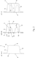
- FIG. 1 shows a bumper cross member assembly 1 in plan view.
- the bumper cross member 2 is coupled to crash boxes 3 .
- the bumper cross member arrangement 1 is then coupled to a motor vehicle body, not shown in detail.
- the bumper cross member 2 has a substantially curved course over its length.
- a central longitudinal section 4 can also be designed to be essentially straight.
- a separate reinforcement plate 5 shown here is arranged in a central longitudinal section 4 in the bumper cross member 2 and is coupled to a locking plate 13 .
- the locking plate 13 with the reinforcement plate 5 is in turn coupled to the front wall or flanges of the bumper cross member 2 .
- the reinforcement plate 5, the locking plate 13 and the bumper cross member 2 or the hollow profile of the bumper cross member 2 are thus concerned three separate components.
- the reinforcement plate 5 is tapered in its depth T.
- the depth T is essentially oriented in the longitudinal direction X of the motor vehicle.
- the central longitudinal section 4 has a longitudinal extent of approximately 20% to 50%, in particular 20% to 40%, of the length L of the bumper cross member 2 .
- the length L refers to the vehicle transverse direction Y.
- the tapered ends 7 increase the distance A between a rear wall 8 of the bumper cross member 2 and the respective tapered end 7.
- the reinforcement plate 5 particularly preferably has no direct contact with the rear wall 8 of the bumper cross member 2 over the entire length.
- a respective length section is designed as a welded length section 9 in which the reinforcement plate is welded to the locking plate 6 .
- the welded longitudinal sections 9 are particularly preferably 5% to 20%, in particular 5% to 10% of the central longitudinal section 4.
- An intermediate longitudinal section 10 that is not welded can thus deform in the event of a crash or the front wall 6 and the reinforcement plate could move relative to one another .
- relief elements 20 can be arranged on the side walls of the crash box 3 that face one another.
- the relief elements 20 can be designed, for example, as a slot, slot, round hole or embossing. A targeted weakening of the crash boxes 3 takes place here.
- the crash boxes 3 can thus move towards one another and thus also promote a deflection of the bumper beam 2, in particular according to FIG Figure 7b .
- Figure 2a, b and c show respective cross-sectional views. It can be seen that the bumper cross member 2 has a closed, hollow profile in its cross section. This is formed from a hat-shaped profile 14, which forms the rear wall 8 and an upper flange 11 and a lower flange 12.
- the front wall 6 is formed by a locking plate 13.
- the strike plate 13 is fitted with the hat profile 14 coupled in particular flanges of the hat profile.
- the reinforcement plate 5 is shown in the hollow profile.
- an end region 7 of the reinforcement plate 5 is shown. This has a depth T7 in the end area 7 which is less than the depth T in the middle area.
- the depth T in the central area is preferably 70% to 100%, particularly preferably 80% to 95% and in particular approximately 85% to 95% of the depth T2 of the bumper cross member 2 in this area. There is thus no direct contact with the rear wall 8 .
- the depth T7 then decreases in the end areas.
- the distance A to the rear wall 8 increases.
- Welds 19 are formed in particular on all contact surfaces of the w-shaped profile on the front wall 6. According to Figure 2c no welding is formed, so that a relative displacement of the reinforcement plate 5 and the front wall in the event of a crash is also possible here, particularly in the transverse direction of the motor vehicle.
- the cross-section remains the same.
- FIG. 3a An alternative design variant is in Figure 3a, b and c represents.
- the cross section of the reinforcement plate 5 according to the Figure 3b flattened or embossed.
- Figure 4a, b and c show an alternative design variant.
- the end area 7 of the reinforcement plate 5 is processed by cutting so that parts of the w-shaped cross section are cut away or cut off.
- figure 5 shows an alternative embodiment figure 1 .
- the ends 7 of the reinforcement profile 5 are followed by a further longitudinal section, which in turn has a depth T in the cross section of the reinforcement profile that is in particular increased compared to the tapered ends 7 .
- This is shown according to section line DD from FIG. 6d.
- the depth T15 here again corresponds to the depth T of the reinforcement plate 5 in the middle section according to FIG Figure 6c .
- FIG. 7a The effect according to the invention is now in comparison in Figure 7a and b shown.
- the bumper assembly 2 is depressed due to a pole or pole 16 or undergoes a bending or curvilinear deformation.
- Figure 7a creates a kink 17.
- no reinforcement plate is used or a reinforcement plate 5 without tapered ends.
- the rear wall of the bumper cross member 8 deforms to the tapered ends 7 of the reinforcement plate 5. This avoids buckling.
- the front wall 6 and also the rear wall 8 can each be displaced relative to the reinforcement plate 5 in the transverse direction of the motor vehicle. On the rear wall 8 this is done according to the principle of a drawstring. There are slight bulges 18 on the front wall 6, but there is no kink or buckling. In this way, it is achieved according to the invention that a targeted deformation for energy reduction is provided without the bumper cross member 2 bottoming out.
- figure 8 1 shows a bumper arrangement 2.
- a soft zone is formed in the upper flange 11 over a length L8, which particularly preferably corresponds to 20% to 40% of the length of the distance A2 between the crash boxes.
- the material properties are changed in this soft zone, in particular the tensile strength is reduced.
- This soft zone can also be present in the bottom chord 12, not shown in any more detail.
- the crash scenario according to Figure 7b is favored by the presence of the soft zone and thus the bending around the post.
- Figure 9a and b show a locking plate 13 in a rear view and a perspective detailed sectional view.
- the locking plate 13 has an arcuate course.
- the reinforcement plate 5 is arranged with its tapered ends 7 on a rear wall 21 of the locking plate 13 itself.
- the reinforcement plate 5 according to FIG Figure 9b joined at the tapered ends 7 with a rear wall 21 of the locking plate 5, in particular welded.
- the striking plate 13 can then be prepared in this way and inserted into a hat profile 14 and the striking plate 13 can in turn be thermally joined to flanges of the hat profile 14, at least in sections along the length.
- the reinforcement plate 5 is optimally positioned and installed.
- the reinforcement plate 5 is in according to this case Figure 9b at least in sections along the length itself hat-shaped.
- the reinforcement plate 5 can thus be produced simply as a sheet metal component, in particular a sheet steel component, using press molding technology.
Landscapes
- Engineering & Computer Science (AREA)
- Mechanical Engineering (AREA)
- Body Structure For Vehicles (AREA)
- Vibration Dampers (AREA)
Abstract
Description
- Die vorliegende Erfindung betrifft einen Stoßfängerquerträger für ein Kraftfahrzeug gemäß den Merkmalen im Oberbegriff von Anspruch 1.
- Aus dem Stand der Technik sind Stoßfängerquerträger bekannt, die an Kraftfahrzeugkarosserien vorderseitig bzw. endseitig gekoppelt sind. Zumeist erfolgt dies unter Eingliederung von Crashboxen. Ein solcher Stoßfängerquerträger ist zumeist aus einem metallischen Werkstoff hergestellt, insbesondere aus einem Stahlwerkstoff oder Leichtmetallwerkstoff und kann auch als Bumper, Stoßfänger oder Querträger bezeichnet werden.
- Ein Stoßfängerquerträger soll eine hinreichende Steifigkeit aufweisen, dass insbesondere beispielsweise bei einem Pohl- oder Pfahltest eine hinreichende Abstützwirkung erreicht wird. Der Stoßfängerquerträger selbst ist also möglichst steif ausgebildet. Das Kraftfahrzeug prallt auf einen Gegenstand auf und die Crashboxen deformieren sich, hierbei wird Crashenergie in Umformarbeit gewandelt.
- Es gibt jedoch auch Stoßfängerquerträger, die sich in einem gewissen Maße verformen sollen, ohne dabei eine Reststeifigkeit zu verlieren. Insbesondere soll der Stoßfängerquerträger beispielsweise bei einem Pohl- oder Pfahltest nicht bei Überschreiten eines Kraftniveaus einknicken bzw. kollabieren.
- Hierzu ist beispielsweise aus der
WO 20 2005 3626 A1 ein Stoßfängerquerträger bekannt, der in einem mittleren Längenabschnitt ein Verstärkungsblech aufweist. Das Verstärkungsblech hilft, den Stoßfängerquerträger im mittleren Bereich zu versteifen. - Aufgabe der vorliegenden Erfindung ist es, einen Stoßfängerquerträger bereitzustellen, der eine hohe Steifigkeit gegen Biegung aufweist, gleichzeitig jedoch bei einem Pohl- oder Pfahltest durch Eigenverformung Crashenergie abbaut, ohne dabei selbst einzuknicken.
- Die zuvor genannte Aufgabe wird von einem Stoßfängerquerträger für ein Kraftfahrzeug mit den Merkmalen im Anspruch 1 gelöst.
- Vorteilhafte Ausgestaltungsvarianten sind Gegenstand der abhängigen Ansprüche.
- Der erfindungsgemäße Stoßfängerquerträger für ein Kraftfahrzeug erstreckt sich in Kraftfahrzeugquerrichtung. Dies erfolgt in der Regel über ein Großteil der Kraftfahrzeugbreite. Der Stoßfängerquerträger selbst ist aus metallischem Werkstoff oder auch aus einem Leichtmetallwerkstoff hergestellt. Der Stoßfängerquerträger weist einen hohlprofilartigen Querschnitt auf, insbesondere eine Hohlkammer. Insbesondere ist dieser Querschnitt hergestellt durch ein einseitig offenes Hohlprofil, insbesondere ein Hutprofil, welches mit einem Schließblech verschlossen ist. Der Querschnitt ist insbesondere wiederum eckig, insbesondere rechteckig ausgebildet. Ein Innenraum des Querschnitts ist insbesondere eckig, ganz besonders bevorzugt rechteckig ausgebildet. Der Stoßfänger ist über Crashboxen an einem Kraftfahrzeug festgelegt. Es kann somit auch eine Stoßfängeranordnung benannt sein.
- Erfindungsgemäß zeichnet sich der Stoßfängerquerträger dadurch aus, dass in einem mittleren Längenabschnitt ein separates Verstärkungsblech eingesetzt ist. Die Tiefe des Verstärkungsblechs in Kraftfahrzeuglängsrichtung nimmt zu den Enden des Verstärkungsbleches ab. Mithin sind die Enden des Verstärkungsbleches verjüngt. Das Verstärkungsblech ist als separates und insbesondere eigenständiges Bauteil ausgebildet. Das Verstärkungsblech ist somit ein separates Bauteil gegenüber dem Schließblech. Das Verstärkungsblech ist ebenfalls ein separates Bauteil gegenüber dem Querträger, insbesondere dem Hohlprofil des Querträgers.
- Hierdurch wird überraschenderweise erfindungsgemäß folgender Vorteil erreicht. Bei einem Auftreffen eines Pohls oder Pfahls, insbesondere mittig des Stoßfängerquerträgers wird der Stoßfängerquerträger bogenförmig eingedrückt bzw. deformiert sich bogenförmig. Durch das Verstärkungsblech im Querschnitt bleibt die Bogenform während des Eindringens möglichst lange erhalten. Ein Einknicken des Querschnitts wird durch das Verstärkungsblech vermieden. Dadurch, dass nunmehr die Enden des Verstärkungsbleches verjüngt sind, schmiegt sich der Querschnitt des Hohlprofils des Stoßfängerquerträgers durch Verformung an die Enden des Verstärkungsbleches an. Ein Einknickvorgang wird somit möglichst lange vermieden. Eine gezielte Biegung bzw. kurvenförmige Deformation wird während des Eindringens des Pohl oder Pfahls hiermit über den Längsverlauf des Querträgers gefördert.
- Im Ergebnis kann somit eine sichere kurvenförmige Deformation des Querträgers bis zum Erreichen eines voreingestellten Lastniveaus erreicht werden, ohne dass zu befürchten ist, dass der Querträger einknickt und damit ein Durchschlagen bzw. ein Durchdringen des Pohls oder Pfahls auf dahinterliegende Antriebsaggregate, Motoren und/oder auch den Fahrgastraum erfolgt. Es kann somit eine hohe Steifigkeit bzw. ein hoher Restwiderstand unter gleichzeitiger kontrollierter Verformung, mithin auch Weichheit bzw. Crashenergieabbau des Stoßfängerquerträgers erreicht werden. Aufwendige weitergehende Maßnahmen zur Nachbearbeitung des Stoßfängerquerträgers werden durch einfaches Einsetzen eines Verstärkungsbleches mit verjüngten Enden vermieden.
- Damit eine Montage der Verstärkungsbleche möglich ist, ist insbesondere vorgehsehen, dass das Hohlprofil als Hutprofil ausgebildet ist, und mit einem Schließblech verschlossen ist. Besonders bevorzugt weist das Schließblech auf die Kraftfahrzeuglängsrichtung nach vorn zeigend mithin die Öffnung des Hutprofils nach vorn zeigend, welche dann mit dem Schließblech verschlossen ist. Das Schließblech bildet in diesem Falle die Vorderwand des Stoßfängerquerträgers. Durch den zweiteiligen Aufbau des Stoßfängerquerträgers kann somit das Verstärkungsblech eingesetzt werden und der Stoßfängerquerträger durch Verschweißen des Schließbleches geschlossen werden. Hierzu ist insbesondere das Verstärkungsblech mit dem Schließblech gekoppelt, insbesondere verschweißt. Diese Kopplung erfolgt zumindest längenabschnittsweise, insbesondere im Endbereich der Verstärkungsbleche. Das Verstärkungsblech ist wiederum an einer Vorderwand des Stoßfängerquerträgers gekoppelt und hier insbesondere je nach Querschnittskontur des Schließblechs selber anliegend. Die verjüngten Enden ergeben dann einen größeren Abstand im Einbauzustand zur Rückwand des Stoßfängerquerträgers.
- Das Schließblech hat in einem zentralen Mittelabschnitt besonders bevorzugt eine Tiefe, die 70 % bis 100 %, bevorzugt 80 % bis 90 % der Tiefe des Hohlprofils des Stoßfängerquerträgers entspricht. Die verjüngten Enden nehmen dann in Kraftfahrzeuglängsrichtung mit einer Tiefe derart ab, dass diese an einem äußeren Endbereich ca. 40 % oder weniger der Tiefe des Querschnitts des Hohlprofils des Stoßfängerquerträgers aufweisen.
- Das Verstärkungsblech weist insbesondere keine unmittelbare Koppelung bzw. Anlage zur Rückwand des Stoßfängerquerträgers auf. Dies ermöglicht im Crashfall das Anschmiegen, mithin eine gezielte Verformung des Stoßfängerquerträgers gegenüber dem Schließblech. Mithin kann sich die Rückwand des Stoßfängerquerträgers relativ zu dem Schließblech bewegen, insbesondere in Kraftfahrzeugquerrichtung.
- Weiterhin besonders bevorzugt erstreckt sich das Verstärkungsblech in Kraftfahrzeugquerrichtung über eine Länge zwischen 20 % und 50 %, bevorzugt zwischen 20 % und 40 % der Länge des Stoßfängerquerträgers selber. Weiterhin besonders bevorzugt weist das Verstärkungsblech im Querschnitt eine profilierte, insbesondere w-förmige Kontur auf. Insbesondere sind die drei Anbindungsstellen der w-Form nach vorne gerichtet angeordnet.
- Das Schließblech ist besonders bevorzugt durch ein Umformverfahren hergestellt. Es kann jedoch auch rollgeformt oder extrudiert werden. Die Verjüngung der Enden wird dann besonders bevorzugt durch ein schneidtechnisches Bearbeiten hergestellt. Alternativ können auch die Enden des Schließbleches durch ein Verprägen bzw. Abflachen in ihrer Tiefe verjüngt werden.
- Das Verstärkungsblech liegt insbesondere an der Vorderwand an. Das Schließblech weist mit seiner Verjüngung dann einen bogenförmigen Verlauf um die Kraftfahrzeugvertikalachse auf, wobei die Innenseite der Bogenform jeweils über einen vorderen Stoßfängerquerträger in Fahrrichtung nach vorne orientiert bzw. beim rückwärtigen Stoßfänger entgegen der Fahrtrichtung, jedoch immer nach außen orientiert ist. Dies entspricht dann der aufnehmenden Kontur für ein zentral auftreffenden Pohl oder Pfahl. Das Verstärkungsblech weist somit keine initiale Deformation bei einem zentralen Aufprall auf.
- Es hat sich weiterhin überraschenderweise gezeigt, dass der zuvor benannte Aspekt des Verstärkungsbleches durch eine Softzone in einem Obergurt und/oder Untergurt des Stoßfängerquerträgers verbessert werden kann. Die Softzone ist insbesondere durch Tailored Properties hergestellt, insbesondere ist der Werkstoff in der Softzone gegenüber dem restlichen Werkstoff des Stoßfängerquerträgers weicher ausgebildet, mithin ist die Zugfestigkeit herabgesetzt. Auch hierdurch wird eine gezielte Deformation des Stoßfängerquerträgers im mittleren Bereich, insbesondere im Bereich der verjüngten Enden des Verstärkungsbleches ermöglicht, die Steifigkeit wird durch das Verstärkungsblech sowie Vorderwand und Rückwand der Stoßfängerquerträger jedoch beibehalten.
- Weitere Vorteile, Merkmale und Eigenschaften der vorliegenden Erfindung sind Gegenstand der nachfolgenden Beschreibung. Bevorzugte Ausgestaltungsvarianten werden in schematischen Figuren dargestellt. Diese dienen dem einfachen Verständnis der Erfindung.
- Es zeigen:
- Figur 1
- eine erfindungsgemäße Stoßfängerträgeranordnung in Draufsicht
- Figur 2 a bis c
- verschiedene Querschnittsansichten
- Figur 3 a bis c
- alternative Querschnittsansichten
- Figur 4 a bis c
- wiederum alternative Querschnittsansichten
- Figur 5
- eine alternative Ausgestaltungsvariante der Stoßfängerträgeranordnung in Draufsicht
- Figur 6 a bis d
- verschiedene Querschnittsansichten zur
Figur 5 - Figur 7 a und b
- eine Gegenüberstellung eines Pohltests eines Stoßfängerquerträgers gemäß Stand der Technik und gemäß der vorliegenden Erfindung
- Figur 8
- eine Ausgestaltung von Softzones an dem Stoßfängerquerträger
- In den Figuren werden für gleiche oder ähnliche Bauteile dieselben Bezugszeichen verwendet, auch wenn eine wiederholte Beschreibung aus Vereinfachungsgründen entfällt.
-
Figur 1 zeigt eine Stoßfängerquerträgeranordnung 1 in Draufsicht. Der Stoßfängerquerträger 2 ist mit Crashboxen 3 gekoppelt. Die Stoßfängerquerträgeranordnung 1 wird dann an einer nicht näher dargestellten Kraftfahrzeugkarosserie gekoppelt. Der Stoßfängerquerträger 2 weist über seine Länge einen im Wesentlichen gekrümmten Verlauf auf. Ein mittlerer Längenabschnitt 4 kann auch im Wesentlichen gerade ausgebildet sein. - In einem mittleren Längenabschnitt 4 ist in dem Stoßfängerquerträger 2 ein hier dargestelltes separates Verstärkungsblech 5 angeordnet und mit einem Schließblech 13 gekoppelt. Das Schließblech 13 mit dem Verstärkungsblech 5 ist wiederum mit der Vorderwand bzw. Flanschen des Stoßfängerquerträgers 2 gekoppelt. Es handelt sich bei dem Verstärkungsblech 5, dem Schließblech 13 und dem Stoßfängerquerträger 2 bzw. dem Hohlprofil des Stoßfängerquerträgers 2 somit um drei separate Bauteile. An den jeweiligen Enden 7 des Verstärkungsbleches 5 ist das Verstärkungsblech 5 in seiner Tiefe T verjüngt ausgebildet. Die Tiefe T ist im Wesentlichen in Kraftfahrzeuglängsrichtung X orientiert. Der mittlere Längsabschnitt 4 weist eine Längserstreckung von ca. 20 % bis 50 %, insbesondere 20 % bis 40 % der Länge L des Stoßfängerquerträgers 2 auf. Die Länge L bezieht sich auf die Kraftfahrzeugquerrichtung Y.
- Durch die verjüngten Enden 7 vergrößert sich der Abstand A zwischen einer Rückwand 8 des Stoßfängerquerträgers 2 und dem jeweils verjüngtem Ende 7. Besonders bevorzugt weist über den gesamten Längsverlauf das Verstärkungsblech 5 keinen unmittelbaren Kontakt mit der Rückwand 8 des Stoßfängerquerträgers 2 auf.
- Ferner ist ein jeweiliger Längenabschnitt als verschweißter Längenabschnitt 9 ausgebildet, in welchem das Verstärkungsblech mit dem Schließblech 6 verschweißt ist. Die verschweißten Längenabschnitte 9 betragen besonders bevorzugt 5 % bis 20 %, insbesondere 5 % bis 10 % des mittleren Längenabschnitts 4. Ein dazwischen liegender nicht verschweißter Längenabschnitt 10 kann sich somit im Crashfalle deformieren bzw. könnte sich die Vorderwand 6 und das Verstärkungsblech relativ zueinander bewegen.
- Weiterhin können besonders bevorzugt Entlastungselemente 20 an den zueinanderweisenden Seitenwänden der Crashbox 3 angeordnet sein. Die Entlastungselemente 20 können beispielsweise als Schlitz, Langloch, Rundloch oder auch Verprägung ausgebildet sein. Hier findet eine gezielte Schwächung der Crashboxen 3 statt. Bei dem in
Figur 7 dargestellten Crashfall können die Crashboxen 3 somit sich aufeinander zubewegen und begünstigen damit ebenfalls eine Durchbiegung des Stoßfängerträgers 2, insbesondere gemäßFigur 7b . -
Figur 2 a, b und c zeigen jeweilige Querschnittsansichten. Zu erkennen ist, dass der Stoßfängerquerträger 2 in seinem Querschnitt ein geschlossenes hohlförmiges Profil ist. Dieses ist aus einem hutförmigen Profil 14 ausgebildet, welches die Rückwand 8 bildet sowie einen Obergurt 11 und einen Untergurt 12. Die Vorderwand 6 wird von einem Schließblech 13 ausgebildet. Das Schließblech 13 ist mit dem Hutprofil 14 insbesondere Flanschen des Hutprofils gekoppelt. Gemäß der Schnittlinien ausFigur 2b und 2c ist das Verstärkungsblech 5 in dem Hohlprofil dargestellt. InFigur 2b ist ein Endbereich 7 des Verstärkungsbleches 5 gezeigt. Dies weist eine Tiefe T7 im Endbereich 7 auf, die geringer ist, als die Tiefe T im mittleren Bereich. Die Tiefe T im mittleren Bereich ist bevorzugt 70 % bis 100 %, ganz besonders bevorzugt 80 % bis 95 % und insbesondere ca. 85 % bis 95 % der Tiefe T2 des Stoßfängerquerträgers 2 in diesem Bereich ausgebildet. Es ist somit kein unmittelbarer Kontakt zur Rückwand 8 ausgebildet. Die Tiefe T7 nimmt dann in den Endbereichen hin ab. Der Abstand A zur Rückwand 8 vergrößert sich. Hier dargestellt ist, dass der w-förmige Querschnitt des Verstärkungsblech 5 vom mittleren Bereich gemäßFigur 2c in seiner Tiefe T zu den Endbereichen 7 hin abnimmt gemäß derFigur 2b . Verschweißungen 19 sind insbesondere ausgebildet an allen Anlageflächen des w-förmigen Profils an der Vorderwand 6. GemäßFigur 2c ist keine Verschweißung ausgebildet, sodass auch hier insbesondere in Kraftfahrzeugquerrichtung eine Relativverschiebung von Verstärkungsblech 5 und Vorderwand im Crashfall möglich ist. Der Querschnitt bleibt jedoch erhalten. - Eine alternative Ausgestaltungsvariante ist in
Figur 3a, b und c darstellt. Hierbei ist der Querschnitt des Verstärkungsbleches 5 gemäß derFigur 3b abgeflacht bzw. verprägt. -
Figur 4 a, b und c zeigen eine alternative Ausgestaltungsvariante. Hier ist der Endbereich 7 des Verstärkungsbleches 5 schneidtechnisch bearbeitet, sodass Teile des w-förmigen Querschnittes weggeschnitten bzw. abgeschnitten sind. -
Figur 5 zeigt eine alternative Ausgestaltungsvariante zuFigur 1 . An die Enden 7 des Verstärkungsprofils 5 schließt sich ein weiterer Längenabschnitt an, der wiederum eine gegenüber den verjüngten Enden 7 insbesondere vergrößerte Tiefe T im Querschnitt des Verstärkungsprofils aufweist. Dies ist gemäß der Schnittlinie D-D aus Figur 6d dargestellt. Die Tiefe T15 entspricht hierbei wiederum der Tiefe T des Verstärkungsbleches 5 im Mittelabschnitt gemäßFigur 6c . Hierdurch kann eine zusätzliche Versteifung bzw. Verstärkung für andere Crashszenarien beispielsweise den RCAR-Bumpertest erreicht werden. - Der erfindungsgemäße Effekt ist nunmehr in Gegenüberstellung in
Figur 7a und b dargestellt. Die Stoßfängeranordnung 2 wird aufgrund eines Pohls bzw. Pfahls 16 eingedrückt bzw. erfährt eine Biegung bzw. kurvenförmige Deformation. GemäßFigur 7a entsteht eine Knickstelle 17. Hierbei ist entweder kein Verstärkungsblech eingesetzt oder ein Verstärkungsblech 5 ohne sich verjüngende Enden. - Gemäß
Figur 7b verformt sich die Rückwand des Stoßfängerquerträgers 8 an die verjüngten Enden 7 des Verstärkungsbleches 5 an. Hierdurch wird ein Einknicken vermieden. Die Vorderwand 6 und auch die Rückwand 8 können sich in Kraftfahrzeugquerrichtung jeweils relativ zu dem Verstärkungsblech 5 verschieben. Auf der Rückwand 8 erfolgt dies nach dem Prinzip eines Zugbandes. An der Vorderwand 6 ergeben sich leichte Aufwölbungen 18, es erfolgt jedoch keine Knickstelle bzw. ein Einknicken. Hierdurch wird es erfindungsgemäß erreicht, dass eine gezielte Verformung zum Energieabbau bereitgestellt ist, ohne dass der Stoßfängerquerträger 2 durchschlägt. -
Figur 8 zeigt eine Stoßfängeranordnung 2. Hierbei ist über eine Länge L8, die besonders bevorzugt 20 % bis 40 % der Länge des Abstandes A2 zwischen den Crashboxen entspricht, eine Softzone im Obergurt 11 ausgebildet. In dieser Softzone sind die Werkstoffeigenschaften verändert, insbesondere ist die Zugfestigkeit herabgesetzt. Diese Softzone kann auch, nicht näher dargestellt, im Untergurt 12 vorhanden sein. Das Crashszenario gemäßFigur 7b wird durch das Vorhandensein der Softzone begünstigt mithin die Biegung um den Pfahl. -
Figur 9a und b zeigen ein Schließblech 13 in einer Rückansicht und einer perspektivischen Detailschnittansicht. Das Schließblech 13 weist einen bogenförmigen Verlauf auf. An einer Rückwand 21 des Schließbleches 13 selber ist das Verstärkungsblech 5 angeordnet mit seinen verjüngten Enden 7. Insbesondere ist das Verstärkungsblech 5 gemäßFigur 9b an den verjüngten Enden 7 mit einer Rückwand 21 des Schließbleches 5 gefügt, insbesondere verschweißt. Das Schließblech 13 kann so vorbereitet dann in ein Hutprofil 14 eingesetzt werden und das Schließblech 13 zumindest längenabschnittsweise mit Flanschen des Hutprofils 14 wiederum termisch gefügt werden. Es findet dadurch eine optimale Positionierung und Montage des Verstärkungsbleches 5 statt. Das Verstärkungsblech 5 ist in diesem Falle gemäßFigur 9b zumindest längenabschnittsweise selbst hutförmig ausgebildet. Das Verstärkungsblech 5 kann somit pressformtechnisch einfach als Blechbautteil insbesondere Stahlblechbauteil hergestellt sein. -
- 1 -
- Stoßfängerquerträgeranordnung
- 2 -
- Stoßfängerquerträger
- 3 -
- Crashbox
- 4 -
- mittlerer Längenabschnitt
- 5 -
- Verstärkungsblech
- 6 -
- Vorderwand zu 2
- 7 -
- Ende zu 5
- 8 -
- Rückwand zu 2
- 9 -
- verschweißter Längenabschnitt
- 10 -
- nicht verschweißter Längenabschnitt
- 11 -
- Obergurt
- 12 -
- Untergurt
- 13 -
- Schließblech
- 14 -
- Hutprofil
- 15 -
- weiterer Längenabschnitt
- 16 -
- Pohl/Pfahl
- 17 -
- Knickstelle
- 18 -
- Aufwölbung
- 19 -
- Verschweißung
- 20 -
- Entlastungselement
- 21 -
- Rückwand zu 5
- A -
- Abstand
- T -
- Tiefe
- T7 -
- Tiefe zu 7
- T15 -
- Tiefe zu 15
- L -
- Länge zu 2
- X -
- Kraftfahrzeuglängsrichtung
- Y -
- Kraftfahrzeugvertikalrichtung
Claims (13)
- Stoßfängerquerträger (2) für ein Kraftfahrzeug, welcher sich in Kraftfahrzeugquerrichtung (Y) erstreckt und im Querschnitt ein Hohlprofil aufweist, insbesondere einen rechteckigen Querschnitt, dadurch gekennzeichnet, dass in einem mittleren Längenabschnitt (4) ein Verstärkungsblech (5) eingesetzt ist, wobei die Tiefe (T) des Verstärkungsbleches (5) in Kraftfahrzeuglängsrichtung (X) zu den Enden (7) des Verstärkungsbleches (5) abnimmt.
- Stoßfängerquerträger (2) nach Anspruch 1, dadurch gekennzeichnet, dass das Hohlprofil als Hutprofil (14) ausgebildet ist, vorzugsweise mit einem Schließblech (13).
- Stoßfängerquerträger (2) nach Anspruch 1 oder 2, dadurch gekennzeichnet, dass das Schließblech (13) in Kraftfahrzeuglängsrichtung (X) nach vorn zeigend angeordnet ist.
- Stoßfängerquerträger (2) nach dem vorhergehenden Anspruch, dadurch gekennzeichnet, dass das Verstärkungsblech (5) im Querschnitt profiliert, insbesondere W-förmig ausgebildet ist.
- Stoßfängerquerträger (2) nach einem der vorangegangenen Ansprüche 1, dadurch gekennzeichnet, dass das Verstärkungsblech (5) sich in Kraftfahrzeugquerrichtung (Y) über eine Länge (L) zwischen 20 und 50%, bevorzugt zwischen 20 und 40% der Länge des Stoßfängerquerträgers (2) erstreckt.
- Stoßfängerquerträger (2) nach einem der vorangegangenen Ansprüche dadurch gekennzeichnet, dass das Verstärkungsblech (5) im Querschnitt wenigstens zwei Schenkel aufweist, welche parallel oder in einem Winkel von nicht mehr als +/-20° zu einem Obergurt und einem Untergurt des Stoßfängerquerträgers (2) angeordnet sind.
- Stoßfängerquerträger (2) nach einem der vorangegangenen Ansprüche, dadurch gekennzeichnet, dass die Verjüngung des Querschnittes des Verstärkungsbleches (5) einen größeren Abstand (A) zu einer Rückwand (8) des Hohlprofils des Querträgers (8) ausbildet, in Relation zu einem mittleren Abschnitt.
- Stoßfängerquerträger (2) nach einem der vorangegangenen Ansprüche, dadurch gekennzeichnet, dass die verjüngten Enden des Verstärkungsbleches (5) durch ein schneidtechnisches Verfahren hergestellt sind oder dass die verjüngten Enden (7) des Verstärkungsbleches (5) durch Abflachen bzw. Verprägen hergestellt sind oder das Verstärkungsblech pressformtechnisch hergestellt ist.
- Stoßfängerquerträger (2) nach einem der vorangegangenen Ansprüche, dadurch gekennzeichnet, dass das Verstärkungsblech (5) längenabschnittsweise, mit der Vorderwand (6) gekoppelt ist, insbesondere verschweißt.
- Stoßfängerquerträger (2) nach einem der vorangegangenen Ansprüche, dadurch gekennzeichnet, dass der Querträger (2) in einem mittleren Längenabschnitt in einem Obergurt (11) und/oder in einem Untergurt (12) eine Softzone aufweist.
- Stoßfängerquerträger (1) nach einem der vorangegangenen Ansprüche dadurch gekennzeichnet, dass der Stoßfängerquerträger (1) durch ein Hutprofil 14 ausgebildet ist mit einem vorne liegenden Schließblech (13), wobei das Verstärkungsblech (15) mit dem Schließblech (13) gekoppelt ist.
- Stoßfängerquerträgeranordnung (1), dadurch gekennzeichnet, dass sie einen Stoßfängerquerträger (2) mit den Merkmalen von mindestens Patentanspruch 1 aufweist, welcher mit Crashboxen (3) gekoppelt ist.
- Stoßfängerquerträgeranordnung (1) nach Anspruch 12 dadurch gekennzeichnet, dass die Crashboxen (3) an ihren aufeinander zu zeigenden Seiten in einem vorderen Bereich Entlastungselemente (20) aufweisen.
Applications Claiming Priority (1)
| Application Number | Priority Date | Filing Date | Title |
|---|---|---|---|
| DE102021128844 | 2021-11-05 |
Publications (2)
| Publication Number | Publication Date |
|---|---|
| EP4177114A1 true EP4177114A1 (de) | 2023-05-10 |
| EP4177114B1 EP4177114B1 (de) | 2023-12-27 |
Family
ID=83903397
Family Applications (1)
| Application Number | Title | Priority Date | Filing Date |
|---|---|---|---|
| EP22202705.4A Active EP4177114B1 (de) | 2021-11-05 | 2022-10-20 | Stossfänger mit integriertem verstärkungsblech |
Country Status (4)
| Country | Link |
|---|---|
| US (1) | US20230143784A1 (de) |
| EP (1) | EP4177114B1 (de) |
| CN (1) | CN116080570B (de) |
| ES (1) | ES2972315T3 (de) |
Cited By (1)
| Publication number | Priority date | Publication date | Assignee | Title |
|---|---|---|---|---|
| EP4570597A1 (de) | 2023-12-15 | 2025-06-18 | Benteler Automobiltechnik GmbH | Bumper mit verstärkungsblech und verbesserter crasheigenschaft |
Families Citing this family (3)
| Publication number | Priority date | Publication date | Assignee | Title |
|---|---|---|---|---|
| CN120129623A (zh) * | 2022-11-03 | 2025-06-10 | 顺普公司 | 车辆加强梁 |
| DE102023117618A1 (de) | 2023-07-04 | 2025-01-09 | Kirchhoff Automotive Deutschland Gmbh | Stoßfängerquerträger |
| DE102024100369B3 (de) | 2024-01-08 | 2025-03-06 | Bayerische Motoren Werke Aktiengesellschaft | Querträger für ein Stoßfängersystem eines Kraftfahrzeugs, Stoßfängersystem mit einem solchen Querträger sowie Kraftfahrzeug mit einem derartigen Stoßfängersystem |
Citations (6)
| Publication number | Priority date | Publication date | Assignee | Title |
|---|---|---|---|---|
| DE102013015421A1 (de) * | 2013-09-18 | 2015-04-02 | Benteler Automobiltechnik Gmbh | Stoßfängersystem und Verfahren für die Herstellung eines Stoßfängersystems |
| CN208411651U (zh) * | 2018-06-25 | 2019-01-22 | 天津市永友工贸有限公司 | 一种稳固的汽车前防撞梁 |
| DE102017123325A1 (de) * | 2017-10-09 | 2019-04-11 | Kirchhoff Automotive Deutschland Gmbh | Stoßfängerquerträger |
| WO2020053626A1 (en) | 2018-09-12 | 2020-03-19 | Arcelormittal | Bumper beam having steel reinforcement |
| DE102018129724A1 (de) * | 2018-11-26 | 2020-05-28 | Benteler Automobiltechnik Gmbh | Fahrzeugbauteil für ein Fahrzeug |
| DE102020104097A1 (de) * | 2020-02-17 | 2021-08-19 | Benteler Automobiltechnik Gmbh | Kraftfahrzeug-Stoßfänger |
Family Cites Families (31)
| Publication number | Priority date | Publication date | Assignee | Title |
|---|---|---|---|---|
| DE2429496A1 (de) * | 1974-06-20 | 1976-01-08 | Volkswagenwerk Ag | Traeger, insbesondere laengstraeger fuer fahrzeuge |
| US4978562A (en) * | 1990-02-05 | 1990-12-18 | Mpa Diversified Products, Inc. | Composite tubular door beam reinforced with a syntactic foam core localized at the mid-span of the tube |
| DE19511868A1 (de) * | 1995-03-31 | 1996-10-02 | Daimler Benz Ag | Stoßstange |
| DE60119187T2 (de) * | 2000-02-17 | 2007-02-01 | Kabushiki Kaisha Kobe Seiko Sho, Kobe | Versteifungsanordnung für Stossstange und Stossstangenhalterung |
| JP4368483B2 (ja) * | 2000-02-28 | 2009-11-18 | 富士重工業株式会社 | バンパビーム構造 |
| US6398289B1 (en) * | 2000-10-19 | 2002-06-04 | Benteler Automobiltechnik Gmbh & Co. Kg | Side impact beam |
| DE10205627A1 (de) * | 2002-02-12 | 2003-08-14 | Suspa Holding Gmbh | Schutzvorrichtung für Kraftfahrzeuge |
| JP2003237507A (ja) * | 2002-02-19 | 2003-08-27 | Om Kogyo Kk | バンパ補強材 |
| DE10248637A1 (de) * | 2002-10-18 | 2004-05-06 | Dr.Ing.H.C. F. Porsche Ag | Stoßfänger für ein Kraftfahrzeug |
| DE102004010792A1 (de) * | 2003-05-17 | 2004-12-09 | Suspa Holding Gmbh | Schutzvorrichtung für Kraftfahrzeuge |
| US6986536B1 (en) * | 2004-06-25 | 2006-01-17 | Shape Corporation | Vehicle bumper beam |
| JP2006036082A (ja) * | 2004-07-28 | 2006-02-09 | Honda Motor Co Ltd | 車両用バンパー構造 |
| US20060028032A1 (en) * | 2004-08-06 | 2006-02-09 | Karl Henseleit | Vehicle bumper and method of making same |
| JP4255909B2 (ja) * | 2004-12-24 | 2009-04-22 | 本田技研工業株式会社 | バンパビーム構造体 |
| JP5267929B2 (ja) * | 2008-09-30 | 2013-08-21 | スズキ株式会社 | 車両前部の構造 |
| JP5329188B2 (ja) * | 2008-11-21 | 2013-10-30 | 株式会社アステア | バンパ補強材 |
| IT1398269B1 (it) * | 2009-03-26 | 2013-02-22 | Red Stamp Sas | Struttura paraurti |
| DE102009056443A1 (de) * | 2009-12-02 | 2011-06-09 | Benteler Automobiltechnik Gmbh | Crashbox und Verfahren zu deren Herstellung |
| JP5223900B2 (ja) * | 2010-10-08 | 2013-06-26 | 日産自動車株式会社 | 車両用バンパー |
| DE102010050013B4 (de) * | 2010-11-02 | 2020-07-09 | Benteler Automobiltechnik Gmbh | Stoßfängeranordnung für ein Kraftfahrzeug |
| JP5403155B2 (ja) * | 2011-03-15 | 2014-01-29 | トヨタ自動車株式会社 | バンパ構造 |
| JP5287927B2 (ja) * | 2011-05-13 | 2013-09-11 | トヨタ自動車株式会社 | 車体構造 |
| JP6014430B2 (ja) * | 2012-09-12 | 2016-10-25 | 株式会社アステア | バンパー |
| DE102013111189B4 (de) * | 2013-10-10 | 2019-08-14 | Benteler Automobiltechnik Gmbh | Stoßfängerquerträger für ein Kraftfahrzeug |
| MX381516B (es) * | 2017-03-24 | 2025-03-12 | Nippon Steel Corp | Miembro de sombrero. |
| JP6550419B2 (ja) * | 2017-05-30 | 2019-07-24 | 株式会社Subaru | バンパビーム構造 |
| JP7056180B2 (ja) * | 2018-01-30 | 2022-04-19 | トヨタ自動車株式会社 | 車両前部の骨格構造 |
| JP7124728B2 (ja) * | 2019-01-25 | 2022-08-24 | トヨタ自動車株式会社 | 車両構造 |
| JP7125826B2 (ja) * | 2019-02-18 | 2022-08-25 | トヨタ車体株式会社 | 衝撃吸収部材及びその製造方法 |
| JP7506499B2 (ja) * | 2020-03-17 | 2024-06-26 | 本田技研工業株式会社 | 車体 |
| WO2022109479A1 (en) * | 2020-11-23 | 2022-05-27 | Shape Corp. | Bumper assembly with reinforced impact dispersion plates |
-
2022
- 2022-10-20 ES ES22202705T patent/ES2972315T3/es active Active
- 2022-10-20 EP EP22202705.4A patent/EP4177114B1/de active Active
- 2022-11-04 US US17/980,610 patent/US20230143784A1/en active Pending
- 2022-11-04 CN CN202211375562.5A patent/CN116080570B/zh active Active
Patent Citations (6)
| Publication number | Priority date | Publication date | Assignee | Title |
|---|---|---|---|---|
| DE102013015421A1 (de) * | 2013-09-18 | 2015-04-02 | Benteler Automobiltechnik Gmbh | Stoßfängersystem und Verfahren für die Herstellung eines Stoßfängersystems |
| DE102017123325A1 (de) * | 2017-10-09 | 2019-04-11 | Kirchhoff Automotive Deutschland Gmbh | Stoßfängerquerträger |
| CN208411651U (zh) * | 2018-06-25 | 2019-01-22 | 天津市永友工贸有限公司 | 一种稳固的汽车前防撞梁 |
| WO2020053626A1 (en) | 2018-09-12 | 2020-03-19 | Arcelormittal | Bumper beam having steel reinforcement |
| DE102018129724A1 (de) * | 2018-11-26 | 2020-05-28 | Benteler Automobiltechnik Gmbh | Fahrzeugbauteil für ein Fahrzeug |
| DE102020104097A1 (de) * | 2020-02-17 | 2021-08-19 | Benteler Automobiltechnik Gmbh | Kraftfahrzeug-Stoßfänger |
Cited By (1)
| Publication number | Priority date | Publication date | Assignee | Title |
|---|---|---|---|---|
| EP4570597A1 (de) | 2023-12-15 | 2025-06-18 | Benteler Automobiltechnik GmbH | Bumper mit verstärkungsblech und verbesserter crasheigenschaft |
Also Published As
| Publication number | Publication date |
|---|---|
| ES2972315T3 (es) | 2024-06-12 |
| EP4177114B1 (de) | 2023-12-27 |
| CN116080570A (zh) | 2023-05-09 |
| CN116080570B (zh) | 2026-04-24 |
| US20230143784A1 (en) | 2023-05-11 |
Similar Documents
| Publication | Publication Date | Title |
|---|---|---|
| EP4177114B1 (de) | Stossfänger mit integriertem verstärkungsblech | |
| DE102013100720B4 (de) | Querträger für ein Kraftfahrzeug | |
| EP4035951B1 (de) | Stossfängeranordnung für ein kraftfahrzeug | |
| EP4035952B1 (de) | Stossfängeranordnung mit zusätzlicher abstützung | |
| DE102018106526A1 (de) | Querträger zur Anordnung an einem Kraftfahrzeug | |
| DE202021103263U1 (de) | Stoßfängeranordnung mit zusätzlicher Abstützung | |
| DE102016200983A1 (de) | Stoßfängeranordnung mit einem Stoßfängerquerträger für ein Kraftfahrzeug | |
| DE102013001668B4 (de) | Karosseriestruktur eines Kraftfahrzeugs und Kraftfahrzeug mit einer derartigen Karosseriestruktur | |
| DE102020104097B4 (de) | Kraftfahrzeug-Stoßfänger | |
| EP3468821B1 (de) | Strukturbauteil für ein kraftfahrzeug mit verstärkungselement | |
| EP4035950B1 (de) | Stossfängeranordnung mit endseitigem hohlprofil | |
| DE102021128850B4 (de) | Stoßfängerquerträger mit lokaler Deformationszone | |
| DE202021103264U1 (de) | Stoßfängeranordnung für ein Kraftfahrzeug | |
| DE102015105625A1 (de) | Stoßfängeranordnung für ein Kraftfahrzeug | |
| DE102008045515B4 (de) | Vorrichtung zur Stoßenergieaufnahme durch plastische Verformung für Kraftfahrzeuge | |
| EP4570597B1 (de) | Bumper mit verstärkungsblech und verbesserter crasheigenschaft | |
| DE102013107179A1 (de) | Stoßabsorptionsvorrichtung für ein Kraftfahrzeug | |
| DE102019108907A1 (de) | Stoßfängeranordnung mit verclinchter Aufnahme | |
| EP4357203B1 (de) | Stossfängeranordnung mit doppelquerträger und abschleppöse | |
| DE102013103719B4 (de) | Tragstruktur eines Kraftfahrzeuges und Verwendung einer Tragstruktur | |
| DE102022120617A1 (de) | Stoßfängeranordnung mit endseitiger Verlängerung | |
| EP3984831A1 (de) | Stossfängeranordnung für ein kraftfahrzeug | |
| EP4389534B1 (de) | Stossfängeranordnung mit querträger | |
| DE102020109579A1 (de) | Träger für ein Kraftfahrzeug und Verfahren zur Herstellung eines Trägers | |
| DE102016124690A1 (de) | Seitenaufprallträger für ein Kraftfahrzeug |
Legal Events
| Date | Code | Title | Description |
|---|---|---|---|
| PUAI | Public reference made under article 153(3) epc to a published international application that has entered the european phase |
Free format text: ORIGINAL CODE: 0009012 |
|
| STAA | Information on the status of an ep patent application or granted ep patent |
Free format text: STATUS: REQUEST FOR EXAMINATION WAS MADE |
|
| STAA | Information on the status of an ep patent application or granted ep patent |
Free format text: STATUS: EXAMINATION IS IN PROGRESS |
|
| 17P | Request for examination filed |
Effective date: 20230404 |
|
| AK | Designated contracting states |
Kind code of ref document: A1 Designated state(s): AL AT BE BG CH CY CZ DE DK EE ES FI FR GB GR HR HU IE IS IT LI LT LU LV MC ME MK MT NL NO PL PT RO RS SE SI SK SM TR |
|
| 17Q | First examination report despatched |
Effective date: 20230428 |
|
| GRAP | Despatch of communication of intention to grant a patent |
Free format text: ORIGINAL CODE: EPIDOSNIGR1 |
|
| STAA | Information on the status of an ep patent application or granted ep patent |
Free format text: STATUS: GRANT OF PATENT IS INTENDED |
|
| RIC1 | Information provided on ipc code assigned before grant |
Ipc: B60R 19/18 20060101ALN20230906BHEP Ipc: B60R 19/24 20060101AFI20230906BHEP |
|
| INTG | Intention to grant announced |
Effective date: 20230921 |
|
| GRAS | Grant fee paid |
Free format text: ORIGINAL CODE: EPIDOSNIGR3 |
|
| GRAA | (expected) grant |
Free format text: ORIGINAL CODE: 0009210 |
|
| STAA | Information on the status of an ep patent application or granted ep patent |
Free format text: STATUS: THE PATENT HAS BEEN GRANTED |
|
| AK | Designated contracting states |
Kind code of ref document: B1 Designated state(s): AL AT BE BG CH CY CZ DE DK EE ES FI FR GB GR HR HU IE IS IT LI LT LU LV MC ME MK MT NL NO PL PT RO RS SE SI SK SM TR |
|
| REG | Reference to a national code |
Ref country code: GB Ref legal event code: FG4D Free format text: NOT ENGLISH |
|
| REG | Reference to a national code |
Ref country code: CH Ref legal event code: EP |
|
| REG | Reference to a national code |
Ref country code: DE Ref legal event code: R096 Ref document number: 502022000356 Country of ref document: DE |
|
| REG | Reference to a national code |
Ref country code: IE Ref legal event code: FG4D Free format text: LANGUAGE OF EP DOCUMENT: GERMAN |
|
| PG25 | Lapsed in a contracting state [announced via postgrant information from national office to epo] |
Ref country code: GR Free format text: LAPSE BECAUSE OF FAILURE TO SUBMIT A TRANSLATION OF THE DESCRIPTION OR TO PAY THE FEE WITHIN THE PRESCRIBED TIME-LIMIT Effective date: 20240328 |
|
| REG | Reference to a national code |
Ref country code: LT Ref legal event code: MG9D |
|
| PG25 | Lapsed in a contracting state [announced via postgrant information from national office to epo] |
Ref country code: LT Free format text: LAPSE BECAUSE OF FAILURE TO SUBMIT A TRANSLATION OF THE DESCRIPTION OR TO PAY THE FEE WITHIN THE PRESCRIBED TIME-LIMIT Effective date: 20231227 |
|
| PG25 | Lapsed in a contracting state [announced via postgrant information from national office to epo] |
Ref country code: LT Free format text: LAPSE BECAUSE OF FAILURE TO SUBMIT A TRANSLATION OF THE DESCRIPTION OR TO PAY THE FEE WITHIN THE PRESCRIBED TIME-LIMIT Effective date: 20231227 Ref country code: GR Free format text: LAPSE BECAUSE OF FAILURE TO SUBMIT A TRANSLATION OF THE DESCRIPTION OR TO PAY THE FEE WITHIN THE PRESCRIBED TIME-LIMIT Effective date: 20240328 Ref country code: FI Free format text: LAPSE BECAUSE OF FAILURE TO SUBMIT A TRANSLATION OF THE DESCRIPTION OR TO PAY THE FEE WITHIN THE PRESCRIBED TIME-LIMIT Effective date: 20231227 Ref country code: BG Free format text: LAPSE BECAUSE OF FAILURE TO SUBMIT A TRANSLATION OF THE DESCRIPTION OR TO PAY THE FEE WITHIN THE PRESCRIBED TIME-LIMIT Effective date: 20240327 |
|
| REG | Reference to a national code |
Ref country code: NL Ref legal event code: MP Effective date: 20231227 |
|
| PG25 | Lapsed in a contracting state [announced via postgrant information from national office to epo] |
Ref country code: NL Free format text: LAPSE BECAUSE OF FAILURE TO SUBMIT A TRANSLATION OF THE DESCRIPTION OR TO PAY THE FEE WITHIN THE PRESCRIBED TIME-LIMIT Effective date: 20231227 |
|
| PG25 | Lapsed in a contracting state [announced via postgrant information from national office to epo] |
Ref country code: SE Free format text: LAPSE BECAUSE OF FAILURE TO SUBMIT A TRANSLATION OF THE DESCRIPTION OR TO PAY THE FEE WITHIN THE PRESCRIBED TIME-LIMIT Effective date: 20231227 Ref country code: RS Free format text: LAPSE BECAUSE OF FAILURE TO SUBMIT A TRANSLATION OF THE DESCRIPTION OR TO PAY THE FEE WITHIN THE PRESCRIBED TIME-LIMIT Effective date: 20231227 Ref country code: NO Free format text: LAPSE BECAUSE OF FAILURE TO SUBMIT A TRANSLATION OF THE DESCRIPTION OR TO PAY THE FEE WITHIN THE PRESCRIBED TIME-LIMIT Effective date: 20240327 Ref country code: NL Free format text: LAPSE BECAUSE OF FAILURE TO SUBMIT A TRANSLATION OF THE DESCRIPTION OR TO PAY THE FEE WITHIN THE PRESCRIBED TIME-LIMIT Effective date: 20231227 Ref country code: LV Free format text: LAPSE BECAUSE OF FAILURE TO SUBMIT A TRANSLATION OF THE DESCRIPTION OR TO PAY THE FEE WITHIN THE PRESCRIBED TIME-LIMIT Effective date: 20231227 Ref country code: HR Free format text: LAPSE BECAUSE OF FAILURE TO SUBMIT A TRANSLATION OF THE DESCRIPTION OR TO PAY THE FEE WITHIN THE PRESCRIBED TIME-LIMIT Effective date: 20231227 |
|
| REG | Reference to a national code |
Ref country code: ES Ref legal event code: FG2A Ref document number: 2972315 Country of ref document: ES Kind code of ref document: T3 Effective date: 20240612 |
|
| PG25 | Lapsed in a contracting state [announced via postgrant information from national office to epo] |
Ref country code: IS Free format text: LAPSE BECAUSE OF FAILURE TO SUBMIT A TRANSLATION OF THE DESCRIPTION OR TO PAY THE FEE WITHIN THE PRESCRIBED TIME-LIMIT Effective date: 20240427 |
|
| PG25 | Lapsed in a contracting state [announced via postgrant information from national office to epo] |
Ref country code: SK Free format text: LAPSE BECAUSE OF FAILURE TO SUBMIT A TRANSLATION OF THE DESCRIPTION OR TO PAY THE FEE WITHIN THE PRESCRIBED TIME-LIMIT Effective date: 20231227 |
|
| PG25 | Lapsed in a contracting state [announced via postgrant information from national office to epo] |
Ref country code: SM Free format text: LAPSE BECAUSE OF FAILURE TO SUBMIT A TRANSLATION OF THE DESCRIPTION OR TO PAY THE FEE WITHIN THE PRESCRIBED TIME-LIMIT Effective date: 20231227 Ref country code: SK Free format text: LAPSE BECAUSE OF FAILURE TO SUBMIT A TRANSLATION OF THE DESCRIPTION OR TO PAY THE FEE WITHIN THE PRESCRIBED TIME-LIMIT Effective date: 20231227 Ref country code: RO Free format text: LAPSE BECAUSE OF FAILURE TO SUBMIT A TRANSLATION OF THE DESCRIPTION OR TO PAY THE FEE WITHIN THE PRESCRIBED TIME-LIMIT Effective date: 20231227 Ref country code: IT Free format text: LAPSE BECAUSE OF FAILURE TO SUBMIT A TRANSLATION OF THE DESCRIPTION OR TO PAY THE FEE WITHIN THE PRESCRIBED TIME-LIMIT Effective date: 20231227 Ref country code: IS Free format text: LAPSE BECAUSE OF FAILURE TO SUBMIT A TRANSLATION OF THE DESCRIPTION OR TO PAY THE FEE WITHIN THE PRESCRIBED TIME-LIMIT Effective date: 20240427 Ref country code: EE Free format text: LAPSE BECAUSE OF FAILURE TO SUBMIT A TRANSLATION OF THE DESCRIPTION OR TO PAY THE FEE WITHIN THE PRESCRIBED TIME-LIMIT Effective date: 20231227 |
|
| PG25 | Lapsed in a contracting state [announced via postgrant information from national office to epo] |
Ref country code: PT Free format text: LAPSE BECAUSE OF FAILURE TO SUBMIT A TRANSLATION OF THE DESCRIPTION OR TO PAY THE FEE WITHIN THE PRESCRIBED TIME-LIMIT Effective date: 20240429 Ref country code: PL Free format text: LAPSE BECAUSE OF FAILURE TO SUBMIT A TRANSLATION OF THE DESCRIPTION OR TO PAY THE FEE WITHIN THE PRESCRIBED TIME-LIMIT Effective date: 20231227 |
|
| PG25 | Lapsed in a contracting state [announced via postgrant information from national office to epo] |
Ref country code: PT Free format text: LAPSE BECAUSE OF FAILURE TO SUBMIT A TRANSLATION OF THE DESCRIPTION OR TO PAY THE FEE WITHIN THE PRESCRIBED TIME-LIMIT Effective date: 20240429 Ref country code: PL Free format text: LAPSE BECAUSE OF FAILURE TO SUBMIT A TRANSLATION OF THE DESCRIPTION OR TO PAY THE FEE WITHIN THE PRESCRIBED TIME-LIMIT Effective date: 20231227 |
|
| REG | Reference to a national code |
Ref country code: DE Ref legal event code: R097 Ref document number: 502022000356 Country of ref document: DE |
|
| PG25 | Lapsed in a contracting state [announced via postgrant information from national office to epo] |
Ref country code: DK Free format text: LAPSE BECAUSE OF FAILURE TO SUBMIT A TRANSLATION OF THE DESCRIPTION OR TO PAY THE FEE WITHIN THE PRESCRIBED TIME-LIMIT Effective date: 20231227 |
|
| PG25 | Lapsed in a contracting state [announced via postgrant information from national office to epo] |
Ref country code: DK Free format text: LAPSE BECAUSE OF FAILURE TO SUBMIT A TRANSLATION OF THE DESCRIPTION OR TO PAY THE FEE WITHIN THE PRESCRIBED TIME-LIMIT Effective date: 20231227 |
|
| PLBE | No opposition filed within time limit |
Free format text: ORIGINAL CODE: 0009261 |
|
| STAA | Information on the status of an ep patent application or granted ep patent |
Free format text: STATUS: NO OPPOSITION FILED WITHIN TIME LIMIT |
|
| 26N | No opposition filed |
Effective date: 20240930 |
|
| PG25 | Lapsed in a contracting state [announced via postgrant information from national office to epo] |
Ref country code: SI Free format text: LAPSE BECAUSE OF FAILURE TO SUBMIT A TRANSLATION OF THE DESCRIPTION OR TO PAY THE FEE WITHIN THE PRESCRIBED TIME-LIMIT Effective date: 20231227 |
|
| PG25 | Lapsed in a contracting state [announced via postgrant information from national office to epo] |
Ref country code: MC Free format text: LAPSE BECAUSE OF FAILURE TO SUBMIT A TRANSLATION OF THE DESCRIPTION OR TO PAY THE FEE WITHIN THE PRESCRIBED TIME-LIMIT Effective date: 20231227 |
|
| PG25 | Lapsed in a contracting state [announced via postgrant information from national office to epo] |
Ref country code: LU Free format text: LAPSE BECAUSE OF NON-PAYMENT OF DUE FEES Effective date: 20241020 Ref country code: BE Free format text: LAPSE BECAUSE OF NON-PAYMENT OF DUE FEES Effective date: 20241031 |
|
| REG | Reference to a national code |
Ref country code: BE Ref legal event code: MM Effective date: 20241031 |
|
| PG25 | Lapsed in a contracting state [announced via postgrant information from national office to epo] |
Ref country code: IE Free format text: LAPSE BECAUSE OF NON-PAYMENT OF DUE FEES Effective date: 20241020 |
|
| PGFP | Annual fee paid to national office [announced via postgrant information from national office to epo] |
Ref country code: DE Payment date: 20251029 Year of fee payment: 4 |
|
| PGFP | Annual fee paid to national office [announced via postgrant information from national office to epo] |
Ref country code: AT Payment date: 20260113 Year of fee payment: 4 |
|
| PGFP | Annual fee paid to national office [announced via postgrant information from national office to epo] |
Ref country code: FR Payment date: 20251030 Year of fee payment: 4 |
|
| PGFP | Annual fee paid to national office [announced via postgrant information from national office to epo] |
Ref country code: CZ Payment date: 20251015 Year of fee payment: 4 |
|
| PG25 | Lapsed in a contracting state [announced via postgrant information from national office to epo] |
Ref country code: CY Free format text: LAPSE BECAUSE OF FAILURE TO SUBMIT A TRANSLATION OF THE DESCRIPTION OR TO PAY THE FEE WITHIN THE PRESCRIBED TIME-LIMIT; INVALID AB INITIO Effective date: 20221020 |
|
| PGFP | Annual fee paid to national office [announced via postgrant information from national office to epo] |
Ref country code: ES Payment date: 20251216 Year of fee payment: 4 |
|
| PG25 | Lapsed in a contracting state [announced via postgrant information from national office to epo] |
Ref country code: HU Free format text: LAPSE BECAUSE OF FAILURE TO SUBMIT A TRANSLATION OF THE DESCRIPTION OR TO PAY THE FEE WITHIN THE PRESCRIBED TIME-LIMIT; INVALID AB INITIO Effective date: 20221020 |