EP4177121A2 - Unité de commande pour la mise à disposition d'un fluide hydraulique sous pression - Google Patents
Unité de commande pour la mise à disposition d'un fluide hydraulique sous pression Download PDFInfo
- Publication number
- EP4177121A2 EP4177121A2 EP22205927.1A EP22205927A EP4177121A2 EP 4177121 A2 EP4177121 A2 EP 4177121A2 EP 22205927 A EP22205927 A EP 22205927A EP 4177121 A2 EP4177121 A2 EP 4177121A2
- Authority
- EP
- European Patent Office
- Prior art keywords
- plunger
- sealing
- cylinder
- transmitter unit
- housing body
- Prior art date
- Legal status (The legal status is an assumption and is not a legal conclusion. Google has not performed a legal analysis and makes no representation as to the accuracy of the status listed.)
- Pending
Links
Images






Classifications
-
- B—PERFORMING OPERATIONS; TRANSPORTING
- B60—VEHICLES IN GENERAL
- B60T—VEHICLE BRAKE CONTROL SYSTEMS OR PARTS THEREOF; BRAKE CONTROL SYSTEMS OR PARTS THEREOF, IN GENERAL; ARRANGEMENT OF BRAKING ELEMENTS ON VEHICLES IN GENERAL; PORTABLE DEVICES FOR PREVENTING UNWANTED MOVEMENT OF VEHICLES; VEHICLE MODIFICATIONS TO FACILITATE COOLING OF BRAKES
- B60T7/00—Brake-action initiating means
- B60T7/02—Brake-action initiating means for personal initiation
- B60T7/08—Brake-action initiating means for personal initiation hand actuated
- B60T7/10—Disposition of hand control
- B60T7/102—Disposition of hand control by means of a tilting lever
-
- B—PERFORMING OPERATIONS; TRANSPORTING
- B62—LAND VEHICLES FOR TRAVELLING OTHERWISE THAN ON RAILS
- B62K—CYCLES; CYCLE FRAMES; CYCLE STEERING DEVICES; RIDER-OPERATED TERMINAL CONTROLS SPECIALLY ADAPTED FOR CYCLES; CYCLE AXLE SUSPENSIONS; CYCLE SIDECARS, FORECARS, OR THE LIKE
- B62K23/00—Rider-operated controls specially adapted for cycles, i.e. means for initiating control operations, e.g. levers, grips
- B62K23/02—Rider-operated controls specially adapted for cycles, i.e. means for initiating control operations, e.g. levers, grips hand actuated
- B62K23/06—Levers
-
- B—PERFORMING OPERATIONS; TRANSPORTING
- B62—LAND VEHICLES FOR TRAVELLING OTHERWISE THAN ON RAILS
- B62L—BRAKES SPECIALLY ADAPTED FOR CYCLES
- B62L3/00—Brake-actuating mechanisms; Arrangements thereof
- B62L3/02—Brake-actuating mechanisms; Arrangements thereof for control by a hand lever
- B62L3/023—Brake-actuating mechanisms; Arrangements thereof for control by a hand lever acting on fluid pressure systems
Definitions
- the invention relates to a transmitter unit for providing pressurized hydraulic medium, in particular a transmitter unit for a vehicle, in particular one that is guided by a link.
- the object of the invention is to improve a transmitter unit.
- the transmitter unit designed to provide pressurized hydraulic medium comprises a housing body having a cylinder interior and a plunger element movably mounted in the cylinder interior, with a pressure chamber for the pressurization, which is at least partially delimited by at least part of the plunger element of a hydraulic medium is formed in the cylinder interior and wherein at least one sealing element, i.e. in particular exactly one sealing element or several sealing elements, for sealing the pressure chamber between the plunger element and the housing body in relation to an actuating movement of the plunger element is arranged statically relative to the housing body in the cylinder interior.
- one advantage of the solution according to the invention is that the at least one sealing element is subjected to less severe stress due to the static seal with respect to the housing body and wear of the same is reduced.
- the static arrangement of the at least one sealing element in particular the static arrangement of a plurality of sealing elements, can reduce a required structural height of the cylinder interior and enable a more compact configuration of the encoder unit.
- a hydraulic medium in the pressure chamber is pressurized by the actuating movement of the plunger element.
- the plunger element is mounted in the cylinder interior so as to be movable in particular linearly in a direction axial to a cylinder axis between a pressurized state having in particular several positions of the plunger element and a basic state having in particular several positions of the plunger element.
- a hydraulic medium in the pressure chamber is pressurized by the plunger element and pressurized hydraulic medium is provided by the transmitter unit.
- a plunger spring is provided, which acts on the plunger element in the direction of the basic state.
- the plunger element comprises a sliding section, which is mounted in a guided manner, in particular linearly movable, in a guide section of the cylinder interior, which is preferably formed by the housing body.
- the plunger element comprises a particularly one-piece plunger body, which advantageously has the sliding section.
- the plunger body on the pressure chamber side delimits the pressure chamber.
- the plunger body in particular its part on the pressure chamber side, preferably has an interior space which at least partially forms the pressure chamber.
- the plunger body preferably has an at least essentially cylindrical outer side, in particular from an actuating end to an end thereof on the pressure chamber side, and/or has a radial extension that is at least essentially constant in relation to a plunger axis.
- the plunger element can be made of a wide variety of materials.
- At least the plunger body for example the entire plunger element, is made of metal.
- At least the plunger body of the plunger element is made of plastic, in particular of a duroplast.
- At least one statically arranged sealing element seals against the plunger body and a plunger body with a good surface quality can be formed in a favorable manner from the plastic, in particular the duroplast, so that the smooth plunger body, which moves relative to the sealing element sealing on it, the sealing element is not heavily stressed.
- At least one sealing element that is to say in particular precisely one sealing element or a plurality of sealing elements, no further details have so far been given.
- the wording that at least one sealing element has a feature is to be understood below as meaning that exactly one sealing element or one sealing element of a plurality of sealing elements, preferably at least some, for example all, of the plurality of sealing elements have this feature.
- sealing elements sealing off the pressure chamber are arranged statically relative to the housing body in the cylinder interior in relation to the actuating movement of the plunger element.
- a sealing section formed in particular by the housing body is formed in the cylinder interior, in which a particularly statically sealing sealing element or several particularly statically sealing sealing elements which seal between the plunger element and the housing body is/are arranged.
- the at least one sealing element is arranged radially further to the outside of the cylinder axis than the guide surface and protrudes only slightly in the radial direction beyond an imaginary continuation of the guide surface in order to seal against the plunger element, in particular the plunger body.
- At least one axial fixing surface is provided in the cylinder interior, in particular for position-true contact, for at least one sealing element, which is in particular arranged statically.
- the at least one sealing element is arranged adjacent to the fixing surface and the fixing surface advantageously delimits at least one side an axial displacement of the position of the at least one sealing element relative to the cylinder axis, so that it is held at least approximately in position.
- At least one, in particular statically arranged, sealing element is arranged between two axial fixing surfaces in the direction axial to the cylinder axis.
- the at least one sealing element is advantageously held between the two axial fixing surfaces.
- an axial position shift of the at least one sealing element is limited on both sides.
- the sealing portion extends between the two axial location surfaces.
- a cylinder wall of the housing body delimits the cylinder interior.
- At least one axial location surface is formed by a step in the cylinder wall of the housing body.
- this step is formed between the guide section and the sealing section, with a radial extent of the cylinder interior being greater in the area of the sealing section than in the area of the guide section.
- At least one securing element for at least one sealing element is arranged in the cylinder interior, preferably for holding the at least one sealing element in the correct position.
- the at least one securing element preferably forms at least one axial fixing surface.
- the at least one securing element has at least one securing ring for fixing a position of at least one sealing element, which is preferably arranged statically and seals in particular between the plunger element and the housing body.
- the at least one retaining ring is spring-loaded.
- the particularly spring-loaded locking ring of the locking element bears against an axial stop formed in the cylinder interior, the locking ring preferably being pressed against the stop by the spring loading.
- a position of the retaining ring is fixed in this way and since the loading presses against the stop, an axial stress on the sealing element to be positioned axially is at least reduced, in particular avoided.
- the axial stop is formed by the cylinder wall, in particular a step in the same.
- the pressure chamber adjoins the region of the sealing section in the axial direction in the cylinder interior.
- the cylinder interior preferably has a greater radial extension in the area of the pressure chamber than in the area of the sealing section.
- this step forms the axial stop for the securing element.
- At least one sealing element which seals off a hydraulic chamber that encompasses the pressure chamber and is sealed off from an area surrounding the housing body, is arranged in the cylinder interior.
- this sealing element seals between the plunger element and the housing body.
- At least one sealing element sealing the pressure chamber between the housing body and the plunger element is arranged in the cylinder interior.
- sealing elements in particular the sealing element sealing the pressure chamber, has a sealing lip, the sealing effect thereby preferably being improved.
- sealing lip is arranged on the plunger element in such a way that, in a pressurized state, the pressurized hydraulic medium presses the sealing lip against the plunger element.
- sealing element sealing the hydraulic chamber and/or the sealing element sealing the pressure chamber is arranged as above, for example in the sealing section and/or adjacent to at least one fixing surface and/or axially between two fixing surfaces in the cylinder interior.
- a spacer element is arranged in the axial direction to the cylinder axis between the sealing element that seals the hydraulic chamber to the outside and the sealing element that seals the pressure chamber.
- a space in the hydraulic chamber that is delimited from the pressure chamber can also be formed, into which a compensating channel connected to a reservoir space for storing hydraulic medium can open, in order to compensate for fluctuations in the quantity and/or pressure of the hydraulic medium in the hydraulic chamber.
- the spacer element has at least one fluid-guiding cutout which, in particular, at least partially forms a fluid-guiding connection, formed in at least some of the positions of the plunger element that correspond to the basic state, between a spatial region of the hydraulic chamber into which the equalizing channel opens and the pressure chamber.
- the fluid-guiding cutout is at least partially formed by an opening or several openings, which run(s) from a side of the spacer element facing the cylinder wall to a side of the spacer element facing the plunger element.
- the fluid-guiding cutout is at least partially formed by at least one section that is set back on the side facing the plunger element, in particular a section that is set back relative to a section that makes contact with the plunger element.
- the at least one set-back section extends along the axial extension of the spacer element.
- At least one opening advantageously opens into at least one set-back section.
- At least one opening and/or at least one cavity formed on the set-back section is connected in a fluid-conducting manner to recesses on the plunger element in the fluid-conducting connection that is formed.
- the fluid-guiding recess has at least one set-back section on the side of the spacer element that faces the cylinder wall, with a cavity being formed in particular at least in the region of this section between the spacer element and the cylinder wall, into which preferably at least one opening and/or an inlet opening of a compensating channel opens /flow.
- a compensating channel is preferably provided, in particular connected to a reservoir space, which opens into the hydraulic chamber at an orifice formed in particular in the cylinder wall.
- the orifice opening is formed between two sealing elements sealing between the plunger element and the housing body relative to an axial direction of the cylinder axis, ie advantageously between the sealing element sealing the hydraulic chamber to the outside and the sealing element sealing the pressure chamber.
- the plunger element has at least one recess, for example on its pressure-chamber-side part, which forms a fluid connection between the pressure chamber and the orifice opening in positions of the plunger element that correspond to the basic state, and this fluid connection forms in positions of the plunger element that correspond to the pressurized state closed is.
- this at least one recess on the plunger element extends past the sealing element that seals off the pressure chamber in positions of the plunger element that correspond to the basic state.
- the part of the plunger element with this at least one recess is arranged at least essentially completely in the pressure chamber in positions of the plunger element that correspond to the pressurized state.
- a transmitter unit for providing pressurized hydraulic medium which comprises a housing body with a cylinder interior extending through the housing body from an actuating opening to a cylinder base opening, with a cylinder base element at least in the area the cylinder bottom opening is in particular detachably fastened in the cylinder interior.
- Closure elements and corresponding closure receptacles which accommodate the closure elements in a fastened state, are advantageously provided for the particularly detachable fastening of the cylinder base element.
- the cylinder base element has the closure elements and the closure receptacles are formed in the housing body, in particular in the cylinder interior.
- the cylinder base element is fastened with a bayonet catch in the cylinder base opening, in particular releasably in the fastened state.
- a sealing element is provided between the cylinder base element and the housing body, which sealing element is advantageously held in the correct position, for example, under the action of a spring, in particular by a securing element.
- the same securing element fixes the sealing element sealing between the cylinder base element and the housing body and at least one sealing element sealing between the plunger element and the housing body in their positions.
- the same securing element has a respective securing ring for fixing the position of each sealing element, with the securing rings preferably being connected by a resiliently designed connecting part of the securing element.
- At least one securing element in particular the securing element for the sealing element sealing between the plunger element and the housing body and/or for the sealing element sealing between the cylinder base element and the housing body, has at least one fluid passage formed radially in particular to the plunger axis in order to advantageously have a to connect the radially inner part of the pressure chamber to a radially outer part of the pressure chamber, in which in particular an outlet opening opens, in a fluid-carrying manner.
- a transmitter unit for providing pressurized hydraulic medium comprises a plunger element and a cylinder base element, the plunger element and the cylinder base element being held together by a holding device to form an insert assembly unit that can in particular be preassembled and preassembled .
- the plunger element and the cylinder base element can be pre-assembled in this way, and the fact that the insert assembly unit is held together by the holding device makes it possible to automate the manufacture of the transmitter unit.
- the insert assembly unit is designed as a component that is provided in the cylinder interior and includes components that can be preassembled as such, thereby simplifying production because only the insert assembly unit has to be inserted as one component in the cylinder interior.
- the holding device comprises at least one holding element on the bottom side and at least one holding element on the plunger side.
- the holding element on the bottom side and the holding element on the plunger side together form a snap-on device.
- the holding device holds the plunger element and the cylinder base element in a maximum position relative to one another and blocks a relative movement of the two elements beyond the maximum position.
- the maximum position of the plunger element relative to the cylinder base element is a position in which these two are at a maximum permissible distance from one another.
- the holding device allows a relative movement, for example in the axial direction to a plunger axis between the plunger element and the cylinder base element up to the maximum position, ie in particular as long as the elements are not yet at the maximum permissible distance from one another.
- the plunger element and the cylinder base element are advantageously held in the maximum position during pre-assembly, and in an installed state in the cylinder interior, however, the functionality and mobility of the plunger element are not impaired by the holding device.
- the holding device also defines a minimum position in which the cylinder base element and the plunger element are at a minimum distance from one another, and the holding device preferably allows the movements between the plunger element and the cylinder base element between the minimum position and the maximum position.
- the base-side retaining element and the plunger-side retaining element are mounted so that they can move relative to one another, in particular linearly, as long as the plunger element and the cylinder base element are at a smaller distance than the maximum permissible distance, and the two retaining elements act together in a blocking manner in the maximum position.
- a maximum permissible distance defined by the maximum position between the plunger element and the cylinder base element is greater than distances which the plunger element and the cylinder base element occupy relative to one another when installed in the cylinder interior.
- the holding device comprises a preferably prestressed spring which acts on the plunger element in the direction of the maximum position.
- the spring is preloaded in the maximum position between the plunger element and the cylinder bottom element.
- the insert assembly unit it is favorable that in the insert assembly unit the plunger element and the cylinder base element are held together prestressed in the maximum position and the insert assembly unit thus has sufficient stability for simple assembly and, for example, automated production is made possible.
- the spring of the holding device engages in an interior space of the plunger body and in particular is supported directly or indirectly on the plunger element in the interior space.
- the holding element on the plunger side is arranged in the interior space of the plunger body.
- the spring of the holding device holds the holding element on the plunger side in the interior of the plunger body.
- the plunger spring which acts on the plunger element in the direction of the basic state also forms the spring of the holding device.
- the cylinder base element comprises a socket which at least partially encloses a part of the plunger element on the pressure chamber side, in particular the plunger body, in a stabilizing manner.
- the socket at least partially encompasses at least a part of the plunger element, in particular the plunger body, in particular a part facing the cylinder base element, the socket for example gripping the part in contact with the part or preferably with some play.
- this gives the insert assembly unit greater stability and, for example, the risk of the plunger element slipping and/or tilting relative to the cylinder base element is at least reduced.
- the socket in particular a wall section of the socket, is spaced apart from the cylinder wall of the housing body in a direction radial to the cylinder axis, in particular in the installed state.
- an interior of the socket forms part of the pressure chamber and preferably together with the interior of the plunger body forms at least a large part, favorably at least half, for example at least two thirds, of the pressure chamber.
- the socket in particular a wall section thereof, has at least one fluid passage, for example in the form of at least one recess and/or at least one groove, through which the interior of the socket, which partially forms the pressure chamber, can pass through the socket even when the plunger body is at least partially engaged with a the socket surrounding part of the pressure chamber is connected to carry fluid.
- the cylinder base element can be fastened in the cylinder interior, in particular as explained above, with the spring of the holding device and/or the plunger spring in particular holding the cylinder base element in the fastened state.
- the assembly unit comprises at least one sealing element, in particular for sealing the hydraulic chamber, preferably for sealing the pressure chamber.
- the assembly unit preferably comprises one or more of the sealing elements for sealing between the cylinder base element and the housing body and/or for sealing between the plunger element and the housing body, in particular the sealing elements explained above, preferably all the sealing elements provided.
- the insert assembly unit includes the securing element.
- the insert assembly unit comprises the spacer element.
- the insert assembly unit includes at least most, preferably all, of the components to be inserted in the cylinder interior, so that these can be preassembled together to form the insert assembly unit and only one component needs to be installed in the cylinder interior.
- the transmitter unit includes a compensating tank with a reservoir space, with the reservoir space being provided in particular for storing hydraulic medium and being connected to the hydraulic chamber in the cylinder interior via a compensating channel.
- the expansion tank is preferably formed at least partially by the housing body, which comprises, for example, a reservoir recess that at least partially forms the reservoir space.
- the expansion tank comprises a cover element which, in particular, surrounds at least the reservoir space in a protective manner in relation to its surroundings.
- the reservoir space is formed between the housing body and the cover element.
- a shell element that is preferably at least partially flexible in shape at least partially delimits the reservoir space.
- the cover element encloses the casing element, so that it is advantageously surrounded in a protective manner in relation to the surroundings of the encoder unit.
- the covering element is pressed against the housing body by the cover element, sealing the reservoir space.
- the cover element of the expansion tank is held at least partially by the cylinder base element in a closed state of the expansion tank.
- this achieves a stable fixing of the cover element.
- the cover element comprises at least one retaining arm, preferably several, for example two, retaining arms, which/which at least partially encompasses the cylinder base element, in particular its closure elements, at least when the expansion tank is in the closed state.
- the holding arm or the holding arms engage/engage in a respective closure receptacle.
- At least one retaining arm of the cover element at least partially forms a closure chamber for a corresponding closure element.
- closure elements for fastening the cylinder base element to the housing body also hold the cover element, in particular its holding arms, at least in the closed state of the expansion tank.
- the cover element in particular a hook projection of at least one holding arm, blocks an opening movement of the cylinder base element when the expansion tank is in the closed state, with the cylinder base element being released from the releasable attachment in particular with the opening movement.
- At least one retaining arm of the cover element in particular its hook projection, has a recess through which a closure element blocked by the retaining arm can be guided in order to release the blockage.
- the recess is formed on a side of the holding arm facing away from the side of the cylinder base.
- the spring loading of the cylinder base element keeps it in the blocked state and thus advantageously also secures the cover element in the closed state.
- the cylinder base element is preferably to be moved counter to its spring loading in order to release the blockage, in particular in order to guide the blocked closure element through the recess.
- an outlet opening in particular for the pressurized hydraulic medium, opens into the cylinder interior, in particular into the pressure chamber.
- the outlet opening is formed in the cylinder wall.
- the outlet opening is formed in the cylinder wall in the axial area, in particular in relation to the cylinder axis, in which the securing element that fixes the position of at least one sealing element is arranged.
- the outlet opening is connected to a pressure connection of the master unit, for example via an outlet channel, with the master unit providing the pressurized hydraulic medium to a slave that is connected, for example, via the pressure port.
- At least one connecting piece at least partially having the outlet channel is formed from the housing body.
- the pressure connection and/or the connecting piece is designed in such a way that it extends at least approximately parallel to a direction in which the handlebars extend, at least when the transmitter unit is properly mounted on a handlebar of a handlebar-guided vehicle.
- connection line can be connected to the pressure connection in a space-saving manner.
- the parallel configuration of the connecting piece and/or the pressure connection is made possible by the configuration of the transmitter unit explained above, in particular the arrangement of the sealing elements and/or the configuration of the pressure chamber.
- the housing body can be made of a wide variety of materials.
- the housing body is made of plastic.
- the cylinder interior is delimited by a cylinder wall formed by the housing body, in particular delimited in a direction radial to the cylinder axis.
- a radial expansion of the cylinder interior measured relative to the cylinder axis up to the cylinder wall, increases in stages along its axial extent from the actuating opening to the cylinder base opening.
- the transmitter unit includes an actuating device for actuating the plunger element.
- an actuating element of the actuating device for actuating the plunger element engages through the actuating opening into the cylinder interior.
- the plunger element when the plunger element is actuated by the actuating device, preferably by being acted upon by the actuating element, the plunger element is moved in the direction of the pressurized state.
- an axial stop is formed in the actuating opening, which in particular holds the plunger element in the cylinder interior, and the plunger element is advantageously pressed against the axial stop at least in an initial position by the spring loading in the basic state.
- the greatest possible distance between the plunger element and the cylinder base element in the installed state is defined by the axial stop.
- the greatest possible distance is preferably smaller than the maximum permissible distance defined by the holding device.
- the transmitter unit is a hand-operated transmitter unit.
- the actuating device then comprises a lever device, in particular comprising a handle.
- the transmitter unit is provided for a hydraulic system of a vehicle, in particular a steering-controlled vehicle.
- the transmitter unit includes a bracket for attaching the same to a handlebar.
- the holder includes a clamping device.
- the holder comprises a clip element, with which the housing body can be fastened to a handlebar as a counterpart.
- an outside of the cylinder base element forms an outer bearing surface for contact with the handlebar.
- a vehicle in particular a driver-controlled vehicle, which includes a hydraulic system with a transmitter unit, the transmitter unit having one or preferably more of the features explained above.
- the wording is to be understood at least essentially in connection with an indication that technically conditioned and/or technically irrelevant deviations from the indication are also included.
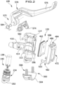
- An exemplary embodiment of a transmitter unit, denoted as a whole by 100, for providing pressurized hydraulic medium is designed, for example, for a hydraulic system of a steering-controlled vehicle and, for example, on a steering 104 of the vehicle in 1 shown.
- the handlebar 104 extends in a handlebar extension direction 106 up to a handlebar grip 108.
- the master unit When it is actuated, the master unit provides pressurized hydraulic medium which, via a hydraulic line of the hydraulic system, reaches a hydraulically activatable slave of the hydraulic system, in particular a hydraulic brake device or, for example, in variants a hydraulic clutch device, and activates it.
- a hydraulically activatable slave of the hydraulic system in particular a hydraulic brake device or, for example, in variants a hydraulic clutch device, and activates it.
- transmitter unit 100 shown disassembled by way of example comprises a housing body 114 of a housing designated as a whole with 120 and having a cylinder interior 112 .
- the cylinder interior 112 delimited by a cylinder wall 128, extends along a cylinder axis 122 between an actuating opening 124 on an actuating side 126 of the housing body 114 and a cylinder base opening 134 on a cylinder base side 136 of the housing body 114, as exemplified in 3 is shown.
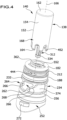
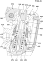
- a plunger element 138 which in particular is part of an example in 4 shown and denoted as a whole by 140, the housing body 114 and the plunger element 138 forming a pressure chamber 142 for pressurizing a hydraulic medium in the cylinder interior 112, as exemplified in FIG figure 5 for a non-actuated ground state and in 6 for a pressurized state realized when the transmitter unit 100 is actuated.
- a guide section 146 emanating from the actuating opening 154 is formed with a guide surface 148 of the cylinder wall 128 that is essentially cylindrical, in particular with respect to the cylinder axis 122, and a plunger body 152 of the plunger element 138 is equipped with an essentially cylindrical sliding section 154 for linearly movable mounting of the plunger element 138 arranged in the cylinder interior 112 in the guide section 146.
- the plunger body 152 which is in particular designed in one piece, extends longitudinally from an actuating end 162 to an end 164 on the pressure chamber side, with the sliding section 154 being formed starting from the actuating end 162.
- a pressure-chamber-side part 168 of the plunger body 152 which includes the pressure-chamber-side end 164, delimits the pressure chamber 142, this part 168 preferably having an interior space in which the pressure chamber 142 is partially formed.
- plunger body 152 has an essentially cylindrical outer shape, so that a maximum radial extent of plunger body 152 relative to a plunger axis 166 of plunger element 138 is at least essentially constant, essentially from actuation end 162 to end 164 on the pressure chamber side, and preferably plunger body 152 has a Plunger axis 166 has a substantially cylindrical outer surface.
- the plunger axis 166 is at least substantially coincident with the cylinder axis 122 .
- the cylinder interior 112 merges into a 7 sealing section 172 shown enlarged, which has a greater radial extent than the guide section 146 in relation to the cylinder axis 122 .
- a sealing step 174 is formed between the guide section 146 and the sealing section 172 .
- a hydraulic chamber sealing element 182 preferably rests against sealing step 174 and is fixed in position, in particular by a fixing surface 176 formed by sealing step 174, the normal of which is oriented at least approximately axially to cylinder axis 152, and seals a hydraulic chamber 184 that includes pressure chamber 142 in the Cylinder interior 112 between the housing body 114 and the plunger element 138 from.
- a pressure chamber sealing element 188 is arranged in the sealing section 172, preferably at an end of the sealing section 172 axially opposite the sealing step 174 to the cylinder axis 122, which seals the pressure chamber 142 between the housing body 114 and the plunger element 138, in particular the part 168 of the plunger body 152 on the pressure chamber side, seals.
- Pressure-chamber sealing element 188 advantageously includes a sealing lip 192 that bears against plunger element 138.
- sealing lip 192 projects away from a wall-side sealing section 194 of pressure-chamber sealing element 188, which bears sealingly against cylinder wall 128 in the area of sealing section 172, so that between wall-side sealing section 194 and the sealing lip 192 has a recess in the pressure chamber sealing element 188 that opens into the pressure chamber 142 and into which the pressurized hydraulic medium of the pressure chamber 142 can penetrate and the sealing lip 192 can press against the plunger element 138 .
- a spacer element 212 embodied, for example, as a spacer ring, which preferably also positions the two sealing elements 182 and 188 and keeps them at least a minimum distance apart.
- a retaining step 216 is advantageously formed in sealing section 172, against which a projection 218 of spacer element 212 strikes in the axial direction of cylinder axis 122, so that hydraulic chamber sealing element 182 is held in the correct position between sealing step 174 and spacer element 212 relative to housing body 214 and, however, through the impact of the projection 218 on the holding step 216 and the associated limited axial mobility of the spacer element 112 in the direction of the hydraulic chamber sealing element 182, this hydraulic chamber sealing element 182 between the sealing step 174 and the spacer element 112 is not overloaded in the axial direction.
- the spacer element 212 and the pressure chamber sealing element 188 preferably engage in one another, for example with form-fit parts thereof, with a projection 222 of the pressure chamber sealing element 188 engaging in a recess 224 of the spacer element 212, for example.
- a securing element 234 comprising a securing ring 232 is advantageously provided, with the securing ring 232 holding the seals, here the hydraulic chamber sealing element 182 and the pressure chamber sealing element 188, in the sealing section 172 with a fixing surface 235.
- Securing ring 232 advantageously rests against an axial securing stop 236, which is formed in particular by a step formed in cylinder wall 128 on an end of sealing section 172 facing pressure chamber 142, and securing ring 232 is advantageously spring-loaded against axial securing stop 236.
- seals are thus retained in the correct position in the sealing section 172 by the retaining ring 232, but axial overstressing of the seals is prevented by the fact that the retaining ring 232 rests against the axial retaining stop 236 and does not directly load the seals.
- the sealing elements 182 and 188 are thus chambered in the sealing section 172 , in particular between the sealing step 174 and the securing ring 232 , and are arranged offset radially back in relation to the guide surface 148 in the guide section 146 .
- a cylinder base element 252 is inserted in the cylinder base opening 134 in the cylinder interior 112, which closes the cylinder interior 112 and the pressure chamber 142 on the cylinder base side, and a cylinder base seal 256 is provided, which seals between the cylinder base element 252 and the cylinder wall of the housing body 114.
- the cylinder base element 252 preferably has a circumferential sealing step 258 in which the cylinder base sealing element 256 lies and projects radially somewhat beyond the edge of the cylinder base element 252 toward the cylinder axis 122 in order to bear sealingly against the cylinder wall.
- a particularly spring-loaded locking ring 262 is provided, which holds the cylinder base sealing element 256 in the correct position on the sealing step 258 .
- Securing element 234 favorably also forms circlip 262 holding cylinder base sealing element 256, with the two circlips 232 and 262 of securing element 234 advantageously being connected to one another by a resilient connecting part 264, as also shown in FIG 4 is shown.
- the securing element 234 is thus supported on the one hand with the securing ring 232 on the axial securing stop 236 and on the other hand with the other securing ring 262 on the cylinder base sealing element 256 and is clamped between the latter by the resilient connecting part 264 .
- Free spaces between the struts 266 connecting the retaining rings 232 and 262 form fluid passages 268, which connect a radially inner part of the pressure chamber to a radially outer part of the pressure chamber, into which in particular an outlet opening 412, described in more detail below, opens, such as in FIG 4 and 7 is shown.
- a bayonet catch is provided for fastening the cylinder base element 252 in the cylinder interior 112 .
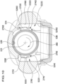
- the cylinder base element 252 has, in particular, two closure elements 272 designed as projections, and closure receptacles 274 corresponding to the closure elements 272 are formed in the cylinder interior 112, as shown individually in FIGS 3 and 4 as well as together in the Figures 8 to 10 is shown.
- closure receptacles 274 have insertion sections 276 designed as recesses in the cylinder wall 128, which open outwards at the cylinder base opening 134 and extend into the housing body 114 in the axial direction with respect to the cylinder axis 122 and are designed to be open in the radial direction into the cylinder interior 112 .
- closure receptacles 274 each have a fastening section 278 in which the respective closure element 272 is seated in a state in which the cylinder base element 252 is fastened in the cylinder interior 112 .
- Fastening section 278 defines a position of closure element 272 at least in the direction axial to cylinder axis 122 toward cylinder base side 136 and blocks a movement of cylinder base element 252 in the direction axial to cylinder axis 122 toward cylinder base side 136.
- the fastening sections 278 are formed as recesses in the cylinder wall 128 that start from the respective insertion section 276 of the closure receptacle 274 and extend in a closure direction 282 oriented around the cylinder axis 122 in a circumferential direction.
- a fixture generally designated 310, is provided for holding the plunger member 138 and cylinder base member 252 together into the cartridge assembly unit 140. As shown in FIG.
- the insert assembly unit 140 which is exemplified in 4 in a not yet fully assembled condition and in 11 shown in a state inserted in the cylinder interior 112, also includes in particular the hydraulic chamber sealing element 182, the pressure chamber sealing element 188, the spacer element 212, the securing element 234 and the cylinder bottom sealing element 256.
- Holding device 310 comprises, in particular, a plunger-side holding element 312 and a bottom-side holding element 314, which is formed from cylinder bottom element 252, which are connected to one another in particular in a latched manner such that plunger element 138 relative to cylinder bottom element 252 in the axial direction of plunger axis 166 relative to one another up to a maximum position in which the plunger element 138 is at a maximum distance from the cylinder base element 252, are displaceable relative to one another and axial movement of the plunger element 138 beyond the maximum position is blocked.
- the base-side retaining element 114 is embodied as a sleeve 322 that is aligned coaxially with the plunger axis 166 in the assembled state, which extends from a base section 324 formed by the cylinder base element 252 in the direction of the plunger element 138 and has an opening that is oriented toward the plunger element 138 Opening 326 has.
- the holding element 312 on the plunger side comprises, in particular, a plunger 332 which protrudes into the sleeve 322 with a locking head 334 and is thus guided by the sleeve 322 and mounted so that it can move in a linear manner relative to the latter.
- a radial extent of the sleeve opening 326 is somewhat reduced by a collar 336 compared to a radial extent of an interior space 338 of the sleeve 322, so that the locking head 334, which essentially has a radial extent like the interior space 338, upon an axial movement of the plunger element 138 away from the cylinder base member 252 in the maximum position abuts the collar 336, blocking further such movement.
- the latching head 334 has a beveled surface at its axial end and thus the part that abuts the collar 336 in the maximum position, in the axial direction opposite, and/or the collar 336 has a beveled surface on its outward-facing side , so that the opening 326 widens outwards, so that the bevelled surfaces at least facilitate the insertion of the plunger 332 with the latching head 334 into the interior space 338 of the sleeve 322 .
- the sleeve 322 has a certain flexibility in the area of the collar 336, so that the locking head 334 can be pressed into the interior 338 of the sleeve 322, for example supported by the beveled surfaces, but the sleeve 322 is also sufficiently stable in the area of the collar 336, such that escape of the latch head 334 through the aperture 326 narrowed by the collar 336 is blocked.
- the plunger 332 extends through a hollow interior 342 of the plunger body 152, the interior 342 opening into the cylinder interior 112 and facing the cylinder base element 252 at the compression chamber end 164 of the plunger body 152.
- the plunger 332 is formed at its end axially opposite the latching head 334 on a fastening body 352 firmly connected to the plunger body 152 .
- Fastening body 352 is enclosed, in particular, in a chamber 354 of interior space 342, and fastening body 352 has ribs 356, for example on the peripheral side, which protrude radially to plunger axis 166 somewhat further than the extent of chamber 354, so that fastening body 352 with ribs 356 in of the chamber 354 is braced.
- the fastening body 352 is firmly connected to the plunger body 152 in a different manner, preferably in a positive and/or material and/or non-positive manner.
- the fastening body 352, the tappet 332 and the plunger body 152 could also be designed in one piece.
- the holding device 310 includes a spring 362 which is clamped between the cylinder base element 252 and the plunger element 152 and acts on the plunger element 152 in the direction of the maximum position.
- the spring 362 is preloaded in the pre-assembled condition of the insert assembly unit 140 and in the maximum position.
- the spring 362 is preferably supported on the cylinder base section 324 .
- the spring 362 engages the interior space 342 of the plunger body 152 .
- the spring 362 is preferably supported on the retaining element 312 on the plunger side.
- a radially outwardly extending stop collar 366 is formed on the holding element 312 on the plunger side, for example on the end of the plunger 332 opposite the locking head 334, on which the spring 362 is supported.
- the stop collar 366 rests against a step 368 formed in the interior space 342, at which the interior space 342 narrows in the direction of a closed end and at which, in particular, the chamber 354 with the fastening body 352 is connected.
- the spring 362 engages in the interior space 342 of the plunger body 152 .
- the spring 362 is preferably arranged in a manner encompassing the plunger 332 and the sleeve 322 .
- Cylinder base element 252 preferably has a socket 372, which at least partially encloses part 168 of plunger body 152 on the pressure chamber side in a stabilizing manner, and part 168 of plunger body 152 on the pressure chamber side dips into a cavity thereof when the hydraulic medium is pressurized.
- the socket 372 comprises a wall section 374 which extends axially from the base section 324 to the cylinder axis 122 and is at least partially cylindrical on the peripheral side and coaxial to the cylinder axis 122 .
- the socket 372 has a socket opening 376 through which the plunger body 152 with its part 168 on the pressure chamber side engages at least partially in an interior of the socket 372 .
- socket 372 in particular a radial distance between wall section 374 and cylinder axis 122, is so large that sleeve 322 and spring 362, which encompasses sleeve 322, are arranged inside socket 372 and between spring 362 and the Version 372, in particular its wall section 374, the pressure chamber side part 168 of the plunger body 152 can move.
- Wall section 374 preferably has at least one radially continuous recess 378, which extends, for example, starting from mount opening 376, axially into wall section 374, as an additional connection, in particular to mount opening 376, between the interior of mount 372 and the area surrounding mount 372, which at least form parts of the pressure chamber 142 .
- At least one groove 379 is formed on the side of wall section 374 that delimits the interior of socket 372, which, on the one hand, extends in the axial direction to plunger axis 166 deeper into the interior of socket 372 than plunger body 152 reaches into the interior, and, on the other hand, also when the plunger body 152 is engaged, opens into a portion of the pressure chamber 142 surrounding the socket 372, as exemplified in FIG 6 and 7 is shown.
- the groove 379 extends to an end of the wall section 374 axially opposite the bottom section 324, preferably to the recess 378 or, in variants, to the socket opening 376.
- the groove 379 thus also connects an engaging plunger body 152 in the interior of the socket 372 and in the interior 342 of the plunger body 152 situated part of the pressure chamber 142 with a socket 372 surrounding part of the pressure chamber 142.
- a fastening wall section 382 preferably extends from cylinder base section 324 of cylinder base element 252 in the axial direction to cylinder axis 122, which attaches at least partially in the region of cylinder base opening 134 to an end section 384 of cylinder wall 128.
- fastening wall section 382 forms a lower part of wall section 374 of mount 372, with the further axial extent of wall section 374 reducing a wall thickness of wall section 374 measured in the radial direction, and sealing step 258 for cylinder base sealing element 256 on the radial outside of the Wall section 374 is formed, up to which, for example, the attachment wall section 382 extends.
- a tapered section 386 is provided, at which a radial extent of cylinder interior 112 decreases at least somewhat as the axial extent into housing body 114 increases, and fastening wall section 382 preferably lies on both sides of tapered section 386 in relation to the axial direction on the cylinder wall 128.
- An outlet opening 412 is formed in cylinder wall 128 in the area of pressure chamber 142, in particular in a section of cylinder wall 128 extending from axial securing stop 236 in the direction of cylinder base opening 134, from which outlet opening 414 an outlet channel 414 leads, for example to a pressure connection 416 of the master unit 100, stretches across.
- the housing body 114 forms a connecting piece 418 which at least partially encompasses the outlet channel 414 and which, for example, also forms the pressure connection 416 or to which the pressure connection 416 can be connected and fastened.
- the connecting piece 416 preferably extends at least approximately parallel to the direction in which the handlebar extends.
- the outlet opening 412 is preferably formed in an axial region between the two retaining rings 232 and 262 and advantageously at least substantially directly opposite the at least one recess 378 in the wall section 374 .
- an inlet opening 432 is formed in cylinder wall 128 in the region of sealing section 172 in a section that is axial to cylinder axis 122 between hydraulic chamber sealing element 182 and pressure chamber sealing element 188, at which inlet opening a compensating channel 434 opens into cylinder interior 112 and in particular into hydraulic chamber 184, with the Part of the hydraulic chamber 184, into which the compensating channel 434 opens, is separated from the pressure chamber 142 by the pressure chamber sealing element 188 in the pressurized state of the plunger element 138.
- the equalization channel 434 leads into a reservoir space 436 of an equalization tank 438, the reservoir space 436 being provided for storing hydraulic medium and an exchange of hydraulic medium between the reservoir space 436 and the hydraulic chamber 184 being able to take place via the equalization channel 434.
- plunger element 138 In order to enable equalization with hydraulic medium between pressure chamber 142 and reservoir space 436 when plunger element 138 is in the basic state, and to allow pressurization of the hydraulic medium in pressure chamber 142 when plunger element 138 is pressurized, plunger element 138, in this case the plunger body, has 152 has recesses 452 in the area of its pressure-chamber-side part 168, which, in the positions corresponding to the basic state of plunger element 138, establish a fluid connection between pressure chamber 142 and that part of hydraulic chamber 184 into which inlet opening 432 opens, and thus a fluid connection between pressure chamber 142 and the reservoir space 436, but this fluid connection is interrupted in the positions corresponding to the pressurized state of the plunger element 138.
- the cutouts 452 extend from the pressure-chamber-side end 164 of the plunger body 152 in the axial direction relative to the plunger axis 166 to such an extent that in positions of the plunger element 138 that correspond to the basic state, the cutouts 452 extend past the pressure-chamber sealing element 188 in the axial direction, as shown in FIG figure 5 is shown, but the section of the plunger body 152 with the recesses 452 is arranged completely in the pressure chamber 142 in positions corresponding to the pressurized state of the plunger element 138, as exemplified in FIG 6 is shown.
- pressure chamber sealing element 188 bears in a sealing manner against a section of plunger element 138, in this case plunger body 152, which is designed to be closed circumferentially relative to plunger axis 166, so that pressure chamber 172 is separated in a fluid-tight manner from that part of hydraulic chamber 184 into which inlet opening 432 opens is.
- the recesses 452 extend continuously in the direction radial to the plunger axis from an outside of the plunger body into the interior 342 of the plunger body 152.
- the spacer element 212 has openings 444, which run from a side of the spacer element 212 that faces the cylinder wall 128 to a side of the spacer element 212 that faces the plunger element 138, as shown by way of example in FIG 7 is shown.
- openings 444 preferably open into at least one section 446 that is set back relative to a section that makes contact with plunger element 138 and that is embodied, for example, as a groove running along the axial extent of spacer element 212, with a groove on the at least one or a cavity formed on a respective recessed section 446 is connected to the recesses 452 in a fluid-conducting manner in positions of the plunger element 138 that correspond to the basic state.
- spacer element 212 has a recessed section 448 on the side facing cylinder wall 128, with a cavity being formed at least in the area of this section 448 between spacer element 212 and cylinder wall 128, into which cavity openings 444 and inlet opening 432 open.
- this at least supports and/or enables the hydraulic medium to flow between the inlet opening 432 and the recesses 452 in the plunger body 152 .
- reservoir space 436 is at least partially delimited by a reservoir recess 456, in particular on the outside, in housing body 114 and by a shell element 458 that is preferably at least partially flexible in shape, shell element 458 being embodied, for example, as a bellows and/or comprising a membrane.
- Envelope element 458 comprises in particular a sealing section 462 embodied, for example, as a beaded section, which, for example with at least two sealing lips 464, rests against a sealing region 468 surrounding the reservoir recess 456 in a closed manner on the peripheral side in a fluid-tight manner.
- a cover element 472 is provided, in particular as part of the housing 120, which extends over the entire circumference of the casing element 458 towards an area surrounding the encoder unit 100, as shown by way of example in FIG 2 and 5 is shown.
- the cover element 472 comprises an application part 474, which is in particular a circumferentially closed edge section of the cover element 472, with the application part 474 being used to press the sealing section 462 of the sleeve element 458 against the sealing area 468 of the housing body 114 in a fluid-tight manner.
- the application part 474 preferably comprises an application projection 476, which presses on the sealing section 462, and a spacer 478, designed in particular as a wall extension, which bears against the sealing area 468 and via which the main force connection occurs when the sealing section 462 is acted upon.
- the sleeve element 458 is thus arranged between the housing body 114 and the cover element 472 and its sealing section 462 seals between the cover element 472 and the housing body 114 .
- the cover element 472 is in particular fastened to the housing body 114 with a fastening device designated 482 as a whole, in particular in such a way that it is pressed against the housing body 114 with the force required to act on the sealing section 462 .
- Fastening device 482 includes, for example, at least one snap-in device 484 provided in particular on actuation side 126, which includes in particular a tab 486 on cover element 472, tab 486 latching in a fastened state on a latching element formed on housing body 114, wherein in 6 only a section 488 of the latching element that is not in direct contact with the tab 486 is shown as an example.
- the fastening device 482 comprises two retaining arms 522 formed on the cover element 472, which, in particular in the fastened state, at least partially encompass the cylinder base element 252 in a hook-like manner.
- openings 524 there are two openings 524, one of which is shown in an example in 3 can be seen, formed in the housing body 114, which extend from the outside, in particular from the side of the housing body 114 on which the reservoir recess 456 is formed, into a respective closure receptacle 274, in particular into its fastening section 278.
- the retaining arms 522 extend through the openings 524 into the closure receptacles 274 and, for example with a hook projection 528 at the ends thereof, enclose a respective closure element 272, as exemplified in FIG 10 is shown.
- closure receptacles here for example closure receptacle 274I
- a hook projection 528 formed at the end of the retaining arm 522I that engages therein lies in the rear end of the fastening section 278 in relation to the direction of closure 282, and an indentation 532I is formed in the retaining arm 522I, in which the closure element 272 accommodated by this closure receptacle 274I can be positioned.
- the indentation 532 extends along the holding arm 522 into the area of the transition from the fastening section 278 into the insertion section 276, so that the closure element 272 can be positioned through the insertion section 276 through the indentation 532 into the fastening section 278, for example in abutment with the hook projection 528I .
- the other holding arm here the holding arm 522II, also has an indentation 532II which, in the fastened state, is positioned in the fastening section 278II of the further closure receptacle 274II and into which the other closure element 272II can be positioned in the fastened state.
- This holding arm 522II also has a hook projection 528II at its end.
- the hook projection 528II is arranged in the fastened state in a transition area between the insertion section 276II and the fastening section 278II.
- the hook projection 528II is preferably not formed over the entire height of the holding arm 522II, with the height of the holding arm 522 being measured in the attached state in the axial direction to the cylinder axis 122, but rather only in a lower region of the end of the holding arm 522, with the lower area relative to the cylinder axis 122 with a properly inserted holding arm 522II is an area axially facing the cylinder base side 136 with respect to the cylinder axis 122 .
- the hook projection 528II thus rests against a wall region of the fastening section 278II facing the side 136 of the cylinder base.
- a recess 534 is formed at the end of this holding arm 522II, which is shown by way of example in FIGS 8 and 10 can be seen, through which an open area 536 connecting the insertion section 276II to the fastening section 278II remains even when the holding arm 522II is inserted into the closure receptacle 274II.
- the recess 534 and thus the hook projection 528II are formed in such a way that the remaining open area 536 is large enough for the corresponding closure element 272II to be inserted through the remaining open area 536 from the insertion section 276II into the fastening section 278II and the indentation 532II and positioned there can be, for which an axial lifting of the closure element 272II is required in particular against the action of the spring 362 via the hook projection 528II.
- a closure chamber 538 is thus formed in closure receptacle 274II, which extends from a chamber base formed by fastening section 278II in the axial direction relative to cylinder axis 122 and in the circumferential direction about cylinder axis 122 in closure direction 282, for example through a section of retaining arm 522 and/or a region of the housing body 114 that delimits the fastening section 278, and is delimited by the hook projection 528 in the direction opposite to the closing direction 282.
- the spring 362 of the holding device 310 also acts as a plunger spring 552 which urges the plunger element 138 in the direction of the basic state.
- actuation opening 124 for example as a collar section protruding into actuation opening 124, as exemplified in 3 is shown, formed against which the plunger element 138 is pressed by the plunger spring 552 in the unactuated basic state of the transmitter unit 100 .
- the encoder unit 100 also includes an example in 2 illustrated actuating device 572, which comprises an actuating element 574 which, when actuating device 572 is actuated, engages through actuating opening 124 into cylinder interior 112, and plunger element 138 in the direction axial to cylinder axis 122 into cylinder interior 112, counter to the action of plunger spring 552 and thus moves against the action of the spring 362 of the holding device 310 and thus puts the plunger element 138 from the basic state into the pressurized state.
- actuating device 572 comprises an actuating element 574 which, when actuating device 572 is actuated, engages through actuating opening 124 into cylinder interior 112, and plunger element 138 in the direction axial to cylinder axis 122 into cylinder interior 112, counter to the action of plunger spring 552 and thus moves against the action of the spring 362 of the holding device 310 and thus puts the plunger element 138 from the basic state into the pressurized state.
- the transmitter unit 100 is a manually operated transmitter unit and the actuating device 572 is also manually operated.
- the actuating device 572 preferably has a lever arm 578 which includes a handle 576 and is mounted on the housing body 114 so that it can rotate about an axis of rotation 582 and is preferably held in a basic position by a spring 584 .
- the lever arm 578 When the lever arm 578 is actuated, i.e. rotated about the axis of rotation 582, in particular against the action of the spring 584, the lever arm 578 presses on the actuating element 574, which thereby engages in the cylinder interior 112.
- the actuating element 574 is also removed from the cylinder interior 112.
- the transmitter unit 100 also includes a holder 592, which is designed, for example, as a clamping device, for mounting the transmitter unit 100 on a handlebar of a handlebar-controlled vehicle.
- a holder 592 which is designed, for example, as a clamping device, for mounting the transmitter unit 100 on a handlebar of a handlebar-controlled vehicle.
- bracket 592 includes a clip element 594 which, together with a clip part 596 formed by housing body 114, in particular on cylinder base side 136, forms a mount for a section of the handlebar and wherein clip element 594 is connected to clip part 596 by fastening means 598 and, in particular, to a the section of the handlebar arranged between the clasp part 596 and the clasp element 594 can be braced.
- cylinder base element 252 forms at least part of clasp part 596, and a side of cylinder base element 252 that is oriented outward in relation to cylinder interior 112 forms a bearing surface 599 of clasp part 596, against which a part of the handlebar rests in the assembled state.
- the insert assembly unit 140 which can in particular be pre-assembled, comprises the plunger element 138 and the cylinder base element 252, which are held together by the holding device 310 and can thus advantageously be pre-assembled as an assembly.
- the plunger-side holding element 312 and the bottom-side holding element 314 are pressed into a mutually holding state and the assembly unit 140 is stabilized.
- the pressure-chamber-side end 164 of the plunger element 138 is held by the socket 372 in a stabilizing manner, so that a tilting of the plunger element 138 with respect to the cylinder base element 252 relative to the plunger axis 166 is counteracted.
- the stable holding together of plunger element 138 and cylinder base element 252 by holding device 310 with spring 362, which is in particular prestressed, and, for example, the stabilizing gripping around of plunger element 138 by socket 372 at least simplifies automated production of the transmitter unit, since the insert assembly unit has the necessary stability having.
- insert assembly unit 140 preferably includes the sealing elements required for sealing pressure chamber 142 and hydraulic chamber 184, here hydraulic chamber sealing element 182, pressure chamber sealing element 188 and cylinder base sealing element 256, and in particular spacer element 212 and securing element 234, so that advantageously insert assembly unit 140 at least in Essentially includes all parts to be installed in the cylinder interior 112, and thus final assembly of the transmitter unit is simplified, since only the pre-assembled insert assembly unit 140 has to be installed in the cylinder interior 112.
- insert assembly 140 To install insert assembly 140 , insert assembly 140 is inserted plunger 138 first through cylinder base opening 134 into cylinder interior 112 with sliding portion 154 of plunger 138 positioned within guide portion 146 .
- the cylinder base element 252 is fastened to the housing body 114 with the bayonet catch, with the cylinder base element 152 initially having to be displaced axially in relation to the cylinder axis 122 in order to guide the closure elements 272 through the insertion sections 276 to the fastening sections 278.
- the cylinder base element 252 can be rotated in the closure direction 282, with the closure element 272II being guided past the hook projection 528 through the open area at least partially formed by the recess 534 and, as a result the locking elements 272 are positioned in the attachment portions 278 and the locking element 272II is chambered in the locking chamber 538 .
- the spring 362 presses the cylinder base element 252 in the direction of the cylinder base side 136 and thus the closure element 272II into the closure chamber 538.
- Securing element 234 is advantageously supported with one securing ring 232 on axial securing stop 236, so that overloading of sealing elements 182 and 188 arranged between this securing ring 232 and, for example, sealing step 174 in sealing section 172, is avoided.
- the hydraulic chamber sealing element 182 and the pressure chamber sealing element 188 are arranged in the correct position relative to the housing body 114 in the sealing section 172 and are preferably chambered by the sealing step 174 and the retaining ring 232, for example.
- the sealing elements 182 and 188 perform a static sealing function relative to the housing body 114 .
- the cylinder base sealing element 256 is secured in its position with the in particular spring-loaded securing ring 262 .
- Plunger element 138 is mounted so as to be linearly movable in the axial direction relative to cylinder axis 122, with plunger spring 552 acting on plunger element 138 in the direction of actuation opening 124 and thus into the basic state and, in particular in the unactuated basic state, pressing it against axial stop 562 in actuation opening 124.
- recesses 452 form a fluid connection past pressure chamber sealing element 188, so that hydraulic medium can be exchanged between reservoir space 436 and pressure chamber 142 via equalizing channel 434 and inlet opening 432.
- the plunger element 138 When the plunger element is actuated, in particular by means of the actuating device 572, the plunger element 138 is moved linearly towards the cylinder axis 122 towards the cylinder base element 252, counter to the action of the plunger spring 552, and the pressure chamber sealing element 188 completely seals the pressure chamber 142 between the plunger element 138 and the housing body 114 in particular, the fluid connection through the recess 452 to that part of the hydraulic chamber 184 into which the inlet opening 432 opens, is interrupted and with a further such linear movement of the plunger element 138, the hydraulic medium in the pressure chamber 142 is pressurized and, as a pressurized hydraulic medium, via the Outlet port 412 is fed to the pressure port 416 .
- the cover element 472 grips the cylinder base element 252, in particular its closure elements 272, the cover element 472 is held securely on the housing body 114 and the retaining arms 522 enable stable attachment of the cover element.
- this full-plunger solution with the static seals relative to the housing body 114 makes it possible to achieve a lower overall height of the pressure chamber 142 and the hydraulic chamber 184 and thus of the entire transmitter unit 100 .
- the spring 362 of the holding device 310 also forms the plunger spring 552 and thus ensures locking and securing of the cylinder base element 252 and in particular the cover element 472 via its holding arms 522 on the one hand and on the other hand for the loading of the plunger element 138 in the initial state a component-reducing compact solution is realized.
Landscapes
- Engineering & Computer Science (AREA)
- Mechanical Engineering (AREA)
- Transportation (AREA)
- Actuator (AREA)
- Hydraulic Clutches, Magnetic Clutches, Fluid Clutches, And Fluid Joints (AREA)
Applications Claiming Priority (1)
| Application Number | Priority Date | Filing Date | Title |
|---|---|---|---|
| DE102021129024.4A DE102021129024A1 (de) | 2021-11-08 | 2021-11-08 | Gebereinheit |
Publications (2)
| Publication Number | Publication Date |
|---|---|
| EP4177121A2 true EP4177121A2 (fr) | 2023-05-10 |
| EP4177121A3 EP4177121A3 (fr) | 2023-06-14 |
Family
ID=84329891
Family Applications (1)
| Application Number | Title | Priority Date | Filing Date |
|---|---|---|---|
| EP22205927.1A Pending EP4177121A3 (fr) | 2021-11-08 | 2022-11-07 | Unité de commande pour la mise à disposition d'un fluide hydraulique sous pression |
Country Status (2)
| Country | Link |
|---|---|
| EP (1) | EP4177121A3 (fr) |
| DE (1) | DE102021129024A1 (fr) |
Families Citing this family (1)
| Publication number | Priority date | Publication date | Assignee | Title |
|---|---|---|---|---|
| DE102024205980A1 (de) * | 2024-06-26 | 2026-02-12 | Gustav Magenwirth Gmbh & Co. Kg | Geberarmatur für ein hydraulisches Bremssystem oder Kupplungssystem |
Family Cites Families (16)
| Publication number | Priority date | Publication date | Assignee | Title |
|---|---|---|---|---|
| IT986458B (it) * | 1973-06-14 | 1975-01-30 | Fiat Spa | Cilindro maestro per due circuiti utilizzatori separati con valvole a tenuta frontale |
| IT1119298B (it) * | 1979-06-26 | 1986-03-10 | Weber Spa | Cilindro maestro per impianti di frenatura di veicoli a circuiti separati |
| ES8504033A1 (es) * | 1984-05-22 | 1985-04-01 | Bendiberica Sa | Perfeccionamientos en cilindros maestros tandem hidraulicos |
| US5036664A (en) * | 1989-03-09 | 1991-08-06 | Brake And Clutch Industries Australia Pty. Ltd. | Fluid pressure actuator with removable piston and cartridge unit |
| DE4240515A1 (de) | 1992-12-02 | 1994-06-09 | Teves Gmbh Alfred | Hauptzylinder mit Plungerkolben und tiefgezogenem Stufengehäuse |
| DE19520680C2 (de) * | 1995-02-02 | 2001-12-06 | Continental Teves Ag & Co Ohg | Hydraulisches Aggregat |
| DE19537038B4 (de) | 1995-10-05 | 2006-05-24 | Stephan Thies | Geberzylinder |
| DE19751462A1 (de) | 1997-11-20 | 1999-05-27 | Itt Mfg Enterprises Inc | Geberzylinder für hydraulische Bremsanlagen |
| DE19752076A1 (de) * | 1997-11-25 | 1999-05-27 | Schaeffler Waelzlager Ohg | Anbindung einer Kolbenstange am Kolben eines Geberzylinders |
| JP4141548B2 (ja) | 1998-09-30 | 2008-08-27 | 株式会社日立製作所 | マスタシリンダ |
| US6871729B2 (en) * | 2001-03-02 | 2005-03-29 | Freni Brembo S.P.A. | Master cylinder for a brake or clutch of a motorcycle or bike |
| US6581380B2 (en) | 2001-07-16 | 2003-06-24 | Automotive Products (Usa), Inc. | Master cylinder with improved piston guidance |
| DE602004003261T2 (de) * | 2003-01-06 | 2007-05-31 | Nissin Kogyo Co. Ltd., Ueda | Hydraulischer Hauptzylinder für ein Fahrzeug |
| DE102009015674A1 (de) * | 2008-08-05 | 2010-02-11 | Continental Teves Ag & Co. Ohg | Hydraulikaggregat |
| DE102013217056A1 (de) * | 2013-08-27 | 2015-03-05 | Gustav Magenwirth Gmbh & Co. Kg | Geberarmatur |
| CN104417702B (zh) * | 2013-08-27 | 2017-03-22 | 张小红 | 带阀门的油压碟刹 |
-
2021
- 2021-11-08 DE DE102021129024.4A patent/DE102021129024A1/de active Pending
-
2022
- 2022-11-07 EP EP22205927.1A patent/EP4177121A3/fr active Pending
Also Published As
| Publication number | Publication date |
|---|---|
| DE102021129024A1 (de) | 2023-05-11 |
| EP4177121A3 (fr) | 2023-06-14 |
Similar Documents
| Publication | Publication Date | Title |
|---|---|---|
| DE10162657B4 (de) | Anschlussstück für Fluidleitungen sowie damit ausgestattetes fluidtechnisches Gerät | |
| EP0789157B1 (fr) | Ressort à gaz ajustable en longueur | |
| DE19526833A1 (de) | Schnellspannsystem | |
| DE3990401C2 (de) | Ausrückmechanismus für eine Kupplung | |
| DE3049110C2 (de) | Pneumatisches Dreiwege-Ventil | |
| EP1512882A2 (fr) | Cylindre hydraulique | |
| DE10080372B4 (de) | Ausrückvorrichtung mit hydraulischer Betätigung | |
| EP3478969A1 (fr) | Cylindre émetteur, en particulier pour un dispositif hydraulique d'actionnement d'embrayage dans des véhicules | |
| EP2855943B1 (fr) | Maître cylindre | |
| EP4177121A2 (fr) | Unité de commande pour la mise à disposition d'un fluide hydraulique sous pression | |
| WO2022184915A1 (fr) | Dispositif de soupape | |
| DE3991752C2 (de) | Kartusche für einen Einhebelmischhahn mit durch elastische Mittel verstärkten Verbindungsrohren | |
| EP1315915A1 (fr) | Dispositif de fixation d'un systeme hydraulique d'actionnement d'embrayage, notamment d'un cylindre recepteur d'embrayage | |
| DE69121944T2 (de) | Zylinderkolbenvorrichtung | |
| DE102004013662A1 (de) | Hauptbremszylinder mit integrierter Transportsicherung | |
| DE112009000777B4 (de) | Handpumpe zum Pumpen von Kraftstoff | |
| EP3189263B1 (fr) | Dispositif de raccordement pour une conduite de fluide | |
| DE69828952T2 (de) | Kupplung für landwirtschaftliche maschinen | |
| DE4240515A1 (de) | Hauptzylinder mit Plungerkolben und tiefgezogenem Stufengehäuse | |
| EP0887559A2 (fr) | Distributeur à plusieurs voies | |
| WO2018091478A1 (fr) | Système de raccordement pour conduites acheminant un fluide | |
| DE10164676A1 (de) | Verschlussdeckel für Kraftfahrzeugkühler | |
| DE9110126U1 (de) | Thermostatventil | |
| WO2019149308A1 (fr) | Agencement d'actionnement muni d'un carter de cylindre récepteur assemblé sans vis et centré, ainsi que système d'embrayage | |
| EP4509215B1 (fr) | Couvercle de récipient de centrifugeuse de laboratoire et ensemble récipient de centrifugeuse de laboratoire |
Legal Events
| Date | Code | Title | Description |
|---|---|---|---|
| PUAI | Public reference made under article 153(3) epc to a published international application that has entered the european phase |
Free format text: ORIGINAL CODE: 0009012 |
|
| STAA | Information on the status of an ep patent application or granted ep patent |
Free format text: STATUS: THE APPLICATION HAS BEEN PUBLISHED |
|
| AK | Designated contracting states |
Kind code of ref document: A2 Designated state(s): AL AT BE BG CH CY CZ DE DK EE ES FI FR GB GR HR HU IE IS IT LI LT LU LV MC ME MK MT NL NO PL PT RO RS SE SI SK SM TR |
|
| PUAL | Search report despatched |
Free format text: ORIGINAL CODE: 0009013 |
|
| AK | Designated contracting states |
Kind code of ref document: A3 Designated state(s): AL AT BE BG CH CY CZ DE DK EE ES FI FR GB GR HR HU IE IS IT LI LT LU LV MC ME MK MT NL NO PL PT RO RS SE SI SK SM TR |
|
| RIC1 | Information provided on ipc code assigned before grant |
Ipc: B62L 3/02 20060101ALI20230505BHEP Ipc: B60T 7/10 20060101AFI20230505BHEP |
|
| P01 | Opt-out of the competence of the unified patent court (upc) registered |
Effective date: 20230521 |
|
| STAA | Information on the status of an ep patent application or granted ep patent |
Free format text: STATUS: REQUEST FOR EXAMINATION WAS MADE |
|
| 17P | Request for examination filed |
Effective date: 20231213 |
|
| RBV | Designated contracting states (corrected) |
Designated state(s): AL AT BE BG CH CY CZ DE DK EE ES FI FR GB GR HR HU IE IS IT LI LT LU LV MC ME MK MT NL NO PL PT RO RS SE SI SK SM TR |
|
| STAA | Information on the status of an ep patent application or granted ep patent |
Free format text: STATUS: EXAMINATION IS IN PROGRESS |
|
| 17Q | First examination report despatched |
Effective date: 20250910 |
|
| STAA | Information on the status of an ep patent application or granted ep patent |
Free format text: STATUS: THE APPLICATION IS DEEMED TO BE WITHDRAWN |