EP4177192A1 - Poussoir rotatif - Google Patents
Poussoir rotatif Download PDFInfo
- Publication number
- EP4177192A1 EP4177192A1 EP22179066.0A EP22179066A EP4177192A1 EP 4177192 A1 EP4177192 A1 EP 4177192A1 EP 22179066 A EP22179066 A EP 22179066A EP 4177192 A1 EP4177192 A1 EP 4177192A1
- Authority
- EP
- European Patent Office
- Prior art keywords
- containers
- diverting
- diversion
- transport
- pivot axis
- Prior art date
- Legal status (The legal status is an assumption and is not a legal conclusion. Google has not performed a legal analysis and makes no representation as to the accuracy of the status listed.)
- Granted
Links
Images


Classifications
-
- B—PERFORMING OPERATIONS; TRANSPORTING
- B65—CONVEYING; PACKING; STORING; HANDLING THIN OR FILAMENTARY MATERIAL
- B65G—TRANSPORT OR STORAGE DEVICES, e.g. CONVEYORS FOR LOADING OR TIPPING, SHOP CONVEYOR SYSTEMS OR PNEUMATIC TUBE CONVEYORS
- B65G47/00—Article or material-handling devices associated with conveyors; Methods employing such devices
- B65G47/74—Feeding, transfer, or discharging devices of particular kinds or types
- B65G47/82—Rotary or reciprocating members for direct action on articles or materials, e.g. pushers, rakes, shovels
-
- B—PERFORMING OPERATIONS; TRANSPORTING
- B65—CONVEYING; PACKING; STORING; HANDLING THIN OR FILAMENTARY MATERIAL
- B65G—TRANSPORT OR STORAGE DEVICES, e.g. CONVEYORS FOR LOADING OR TIPPING, SHOP CONVEYOR SYSTEMS OR PNEUMATIC TUBE CONVEYORS
- B65G47/00—Article or material-handling devices associated with conveyors; Methods employing such devices
- B65G47/74—Feeding, transfer, or discharging devices of particular kinds or types
- B65G47/84—Star-shaped wheels or devices having endless travelling belts or chains, the wheels or devices being equipped with article-engaging elements
- B65G47/846—Star-shaped wheels or wheels equipped with article-engaging elements
- B65G47/847—Star-shaped wheels or wheels equipped with article-engaging elements the article-engaging elements being grippers
Definitions
- the present invention relates to a device for handling containers, in particular for transporting and diverting containers.
- One method for reducing the number of bottles produced would be to eject, for example, every second or third plastic preform after the oven in the blow molding machine for one oven length, with more than 100 containers per hour usually being ejected
- the object of the present invention is therefore to provide a device for treating containers, in particular a diverting device, which meets the criteria mentioned above.
- the idea is that a rejection device rotates in and out on a rotary drive, depending on whether a container is to be rejected.
- the containers are transported along a predetermined transport path, the transport device having a movable carrier on which a large number of holding devices for holding the containers are arranged.
- the transported containers each have longitudinal directions, with the longitudinal directions of the containers transported by the transport device being aligned parallel to one another and the containers preferably being spaced equidistantly from one another.
- the device according to the invention has a diverting device which is suitable and intended for diverting individual containers from the transport path, the diverting device having a diverting device which has at least one contact area which contacts the containers in order to divert them from the transport path.
- the diverting device can be pivoted and/or rotated with respect to a predetermined pivot axis, with this pivot axis being arranged essentially parallel to the longitudinal directions of the containers.
- the transported containers are preferably plastic preforms for the production of plastic bottles, in particular PET bottles, which have a lateral surface, a mouth opening, a thread and preferably a support ring, with the present invention not being limited to plastic preforms and also for bottles that have already been blow-molded or other containers is applicable.
- the transport device comprises a movable carrier which has a large number of holding devices. In these holding devices, the containers are preferably arranged upright with their mouth pointing upwards, in particular laterally clamped by two clamps, the two clamps preferably being connected via a common pivot axis.
- the individual holding devices and thus also the containers held by them are preferably equidistant from one another, with the longitudinal directions (L) of the containers being aligned parallel to one another and preferably perpendicular to the transport direction.
- the transport device preferably has a circular, rotationally symmetrical transport path or a transport path in the shape of a segment of a circle, linear transport systems not being ruled out.
- the transported containers and the pivot axes of the holding devices preferably rotate around a common geometric center on concentric circles, with the pivot axes being arranged on a circular path closer to the center.
- the clamps of the holding devices are advantageously constructed in such a way that a segment of the lateral surfaces of the containers is contacted in the area of the clamps on the side facing the center point, with the area of the lateral surfaces pointing radially outward advantageously remaining free.
- a diverting device comprises a rotationally mounted pivotable diverting device, the pivot axis being arranged essentially parallel to the longitudinal direction of the containers to be transported.
- the diverting device can be pivoted and/or rotated about the pivot axis, which is preferably arranged stationary within the circular transport path of the containers opposite the transport device.
- the diverting device has at least one contact area which touches the movement path of the containers after the diverting device has swiveled into the path of movement of the containers, as a result of which the container is released from the clamp and diverted outwards from the transport path.
- the contact preferably takes place as close as possible below the clamps in order to achieve optimum force transmission without the containers tilting too much.
- Contact is no more than 15mm, preferably no more than 10mm and more preferably no more than 5mm from the bottom of the brackets.
- the device has a drive device for driving the diversion device.
- This drive device has a rotary motor, preferably a DC motor, asynchronous motor or stepping motor or particularly preferably a synchronous motor and preferably a rotary encoder.
- the drive device is preferably installed under the star wheel of the blow molding machine. Since the drive device with the diversion device can be a danger point, this is preferably integrated into a safety architecture. In this case, an immediate shutdown of the drive and diverting device would be conceivable when a protective cover is opened or when an emergency stop switch is actuated.
- the drive device of the diverting device can be operated at a variable speed, which can be controlled in particular as a function of control signals. It would be conceivable here for an upstream inspection unit to identify defective containers and generate signals for the corresponding containers to be subsequently rejected. It is also conceivable that the diverting device is activated in response to such signals. It would also be conceivable for the diversion device to be started in response to such a signal and to be accelerated from a stationary position, or for the speed of the already rotating diversion device to be changed.
- the diversion device has at least one wing and/or the contact area has at least two different geometries.
- the diversion device can be understood as a body which is firmly connected to the pivot axis and rotates around/with it.
- Such a body, comprising at least one wing could be designed as a rotationally symmetrical body and/or as a body extending only in a radial direction.
- different geometries are understood to mean the surface contours of the diversion device.
- the diverting device is shaped in such a way that the resulting force, which results from the relative movement of the container and the diverting device to one another, runs almost parallel to the clip axis.
- the movement path of the diverting device can be set differently relative to the center point of the container with a different diameter of the container.
- the diverting device can have a different number of wings, which means that different strategies for diverting the containers can be implemented.
- the moment of inertia of the diversion device should, in an advantageous embodiment of the invention device less than 5 kg/cm 2 , preferably less than 3 kg/cm 2 and most preferably less than 2 kg/cm 2 .
- the diverting device has a geometry that actively supports the diverting of the containers. This could be achieved by an appropriate geometry in the contact area of the diverting device, in which the container to be diverted exerts a force on the diverting device and to a certain extent levers itself out of the holding device, more precisely out of the clamps.
- the diameter of the diversion device is less than 125 mm, particularly preferably less than 100 mm and/or greater than 50 mm and particularly preferably greater than 75 mm.
- the diameter is understood as the connecting line of the two points furthest apart, the hypothetical connecting line having to pass through the center point of the diverter and the pivot axis.
- the diversion device has recesses and/or cavities.
- the discharge device is preferably made of plastic or a low-density material, the density being less than 3 g/cm 3 , preferably less than 2 g/cm 3 and particularly preferably less than 1 g/cm 3 .
- the diversion device has precisely one wing and the contact area preferably has a first geometry for dynamic rejection of containers and a second geometry for static rejection of containers.
- the diversion device has a parking position, ie a position in which the wings can rest.
- the diversion device In response to a signal to divert a container, the diverting device can be accelerated in order to carry out a sequence of movements that is synchronized with the movement of the container.
- the first geometry of the contact area hits the container to be diverted and thereby presses it (dynamically) out of the clamp of the holding device of the transport device.
- the diverting device can continue its rotation smoothly in a continuous movement and return to the parking position after a full rotation. If, on the other hand, the following container is also diverted, the diverting device can decelerate considerably after the preceding dynamic diverting of the container, so that the second geometry of the contact area hits the container to be diverted and presses it (statically) out of the clamp of the holding device of the transport device. If every second container is to be diverted, it would be conceivable for the diverting device to rotate in a sequence of movements synchronized with the movement of the containers and for every second container to be dynamically diverted with the first geometry of the contact area. In this case, the parking position would simply be overrun.
- the diversion device has at least two, preferably at least three and particularly preferably at least four wings and/or is moved continuously.
- the diverting device would rotate at a speed synchronized with the movement of the containers.
- the movement of the diverting device would be designed in such a way that the wings of the diverting device cross the transport path of the containers only between them and there is no contact with the containers. If a container is to be diverted, the speed of the diverting device can be increased or reduced, with another wing hitting the next container to be diverted or the previous wing staying on the transport path and hitting the container to be diverted and this being pushed out of the clamp of the holding device .
- the diverting direction is arranged at a tangent to the transport direction or is at an acute angle to the transport direction, so that a discharge can take place in the radial direction.
- the diverting device can be controlled via a connecting rod and a rotary motor connected to it.
- the diverting device would be mounted in rotation via the pivot axis, but would not be driven via it.
- the diversion device would be connected to a spaced-apart rotary motor via a connecting rod and would be controlled by it.
- a DC motor, asynchronous motor or stepper motor or particularly preferably a synchronous motor could preferably be used as the rotary motor.
- the pivot axis of the diversion device is mounted aseptically. It would be conceivable that the containers should be transported and diverted under sterile, aseptic conditions in a clean room. For reasons of economy, it would be advantageous to keep such a clean room as small as possible and that only the diversion device is inside the sterile Room is located and the associated drive device would be outside of the sterile room. In this case, only the pivot axis would have to be guided through the clean room boundaries.
- a diverting device which is suitable and intended for diverting individual containers from a transport path, has a diverting device which has at least one contact area which contacts the containers in order to divert them from the transport path, and a drive device for driving the diverting device.
- the diverting device can be pivoted and/or rotated with respect to a predetermined pivot axis and this pivot axis is arranged essentially parallel to the longitudinal directions of the containers.
- FIG. 1a,b shows a schematic representation of a device 1 according to the invention for treating containers 10 (containers 11 to be rejected, intact containers 12).
- a transport device 2 is provided, for example with a circular or circular segment-shaped transport path and a large number of holding devices 22.
- the holding device 22, in which a container 10 is held by two clamps 24a, b, is also shown in a detailed view.
- the two clamps 24a, b are preferably connected to one another via a common pivot axis 26 and clamp the containers 10 in such a way that the clamp axis 27 (dashed line) points radially outwards. If the diverting device (not shown) hits a container 11 to be diverted, a force acts on it which approximately corresponds to the direction of the clip axis 27 (see drawing), as a result of which the container 11 is pushed slightly out of the clip.
- Fig. 2a-c shows a schematic representation of an advantageous embodiment of the device 1 according to the invention, comprising a transport device 2 and a diverting device 4, wherein the diverting device 41 has a wing 44 which rotates about the pivot axis 43.
- the contact area 42 has a first geometry 45 (here outer contour) for dynamic diversion and a second geometry 46 (here outer contour) for static diversion of the containers.
- the sub-figures a to c show different operating states of the rejection device 4.
- Figure 2a shows the diversion device 41 in a stationary parking position.
- Figure 2b shows the diverting device 41 in the pivoted-in position, with the first geometry 45 of the contact region 42 striking the container 11 to be diverted.
- Figure 2c shows the diverting device 41 in a delayed position, with the second geometry 46 of the contact area 42 striking the container to be diverted.
- the diversion device 41 is in a stationary parking position ( Figure 2a ). If a container 11 is to be diverted, the diverting device 41 accelerates (initiated by a control signal) and strikes the container 11 with the first geometry 45 ( Figure 2b ), which diverts it from the transport path. If the next container 12 is not to be diverted, the diverting device 41 returns to the parking position and can be activated again if necessary.
- the diverting device 41 can be delayed or braked, as a result of which it remains in the transport path and touches the container 11 with the second geometry 46 of the contact area 42 and diverts it from the transport path.
- the diverting device 41 rotates at a speed synchronized with the movement of the containers, and the first geometry 45 of the contact area 42 strikes every second container 11 and removes it from the transport path discharges.
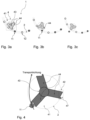
- Fig. 3a-c shows a schematic representation of a further advantageous embodiment of the device 1 according to the invention, comprising a transport device 2 and a diverting device 4, the diverting device 41 having three wings 44 which rotate about the pivot axis 43.
- the sub-figures a to c show different operating states of the rejection device 4.
- Figure 3a shows a state in which the diverting device 41 and the transport device 2 are synchronized and a wing 44 is arranged essentially in the middle between two containers 10.
- Figure 3b shows a state in which the diverting device 41 is being accelerated and a further vane 44 is approaching a container 11 to be diverted.
- Figure 3c shows a state in which the in Figure 3b approaching wing 44 has already discharged the container 11.
- the diverting device 41 rotates - preferably at a speed synchronized to the movement of the containers - in such a way that the wings always cross the transport path between two containers and the containers the diverting device 41 in the area whose recesses pass ( Figure 3a ). If a container 11 is to be diverted, the speed of the diverting device increases (in response to a control signal), as a result of which a wing 44 approaches the container 11 to be diverted ( Figure 3b ) and directs it out of the transport path ( 3c ). Alternatively, the speed of the diverting device can be throttled, as a result of which a wing 44 remains longer on the transport path and a container 11 to be introduced hits it and is diverted as a result.
- the speed of the diverting device is first reduced (lower speed than in the initial state) or increased (higher speed than in the initial state) and shortly thereafter brought back to the initial speed. Should the following container 11 be diverted instead, the diverting device 41 rotates at the initial speed without any interim braking.
- FIG. 4 shows a schematic representation of a further advantageous embodiment of the device 1 according to the invention, comprising a transport device 2 and a diverting device 41, which has three wings 44 and an actively supporting geometry 47 of the contact area 42. If a container 11 to be diverted hits the actively supporting geometry 47 of the diverting device 41, this causes a force to act on the wing 44.
- figure 5 shows a schematic representation of an advantageous embodiment of the device 1 according to the invention, comprising a transport device 2 and a diverting device 4, wherein the diverting device 41 has a wing 44 which rotates about the pivot axis 43.
- the diversion device 41 is connected to a connecting rod 48 and is controlled by this.
Landscapes
- Engineering & Computer Science (AREA)
- Mechanical Engineering (AREA)
- Specific Conveyance Elements (AREA)
- Branching, Merging, And Special Transfer Between Conveyors (AREA)
Applications Claiming Priority (1)
| Application Number | Priority Date | Filing Date | Title |
|---|---|---|---|
| DE202021104385.7U DE202021104385U1 (de) | 2021-08-17 | 2021-08-17 | Rotationspusher |
Publications (3)
| Publication Number | Publication Date |
|---|---|
| EP4177192A1 true EP4177192A1 (fr) | 2023-05-10 |
| EP4177192C0 EP4177192C0 (fr) | 2025-11-12 |
| EP4177192B1 EP4177192B1 (fr) | 2025-11-12 |
Family
ID=77659397
Family Applications (1)
| Application Number | Title | Priority Date | Filing Date |
|---|---|---|---|
| EP22179066.0A Active EP4177192B1 (fr) | 2021-08-17 | 2022-06-14 | Poussoir rotatif |
Country Status (3)
| Country | Link |
|---|---|
| EP (1) | EP4177192B1 (fr) |
| CN (1) | CN220242359U (fr) |
| DE (1) | DE202021104385U1 (fr) |
Families Citing this family (1)
| Publication number | Priority date | Publication date | Assignee | Title |
|---|---|---|---|---|
| DE102021122324A1 (de) * | 2021-08-30 | 2023-03-02 | Krones Aktiengesellschaft | Ausschleuseeinrichtung zum Ausschleusen von Behältnissen mit Kniehebelsystem |
Citations (2)
| Publication number | Priority date | Publication date | Assignee | Title |
|---|---|---|---|---|
| US4793461A (en) * | 1987-02-26 | 1988-12-27 | The Kartridg Pak Co. | Container feed apparatus |
| WO2020115421A1 (fr) * | 2018-12-04 | 2020-06-11 | Sidel Participations | Dispositif, installation et procede d'ejection de produits |
-
2021
- 2021-08-17 DE DE202021104385.7U patent/DE202021104385U1/de active Active
-
2022
- 2022-06-14 EP EP22179066.0A patent/EP4177192B1/fr active Active
- 2022-07-20 CN CN202221884402.9U patent/CN220242359U/zh active Active
Patent Citations (2)
| Publication number | Priority date | Publication date | Assignee | Title |
|---|---|---|---|---|
| US4793461A (en) * | 1987-02-26 | 1988-12-27 | The Kartridg Pak Co. | Container feed apparatus |
| WO2020115421A1 (fr) * | 2018-12-04 | 2020-06-11 | Sidel Participations | Dispositif, installation et procede d'ejection de produits |
Also Published As
| Publication number | Publication date |
|---|---|
| CN220242359U (zh) | 2023-12-26 |
| EP4177192C0 (fr) | 2025-11-12 |
| EP4177192B1 (fr) | 2025-11-12 |
| DE202021104385U1 (de) | 2021-08-23 |
Similar Documents
| Publication | Publication Date | Title |
|---|---|---|
| EP3433205B1 (fr) | Dispositif de transport de contenants | |
| EP2295352B1 (fr) | Dispositif de prise pour tenir et déplacer des articles | |
| EP2179960B1 (fr) | Dispositif de transport de récipients | |
| DE102011007280A1 (de) | Behälterbehandlungsmaschine und Verfahren zur Behälterbehandlung | |
| DE102015209367A1 (de) | Behälterbehandlungsanlage | |
| EP3090969B1 (fr) | Dispositif d'amortissement de fermetures de recipients | |
| DE102021107727A1 (de) | Abfüllanlage und Verfahren zur aseptischen Abfüllung flüssiger Produkte in Flaschen | |
| EP4177192B1 (fr) | Poussoir rotatif | |
| EP0327992A1 (fr) | Dispositif pour élever et aligner des pièces formées | |
| EP4107099B1 (fr) | Dispositif et procédé de transport de contenants | |
| EP3938298B1 (fr) | Dispositif de transport et procédé pour le transport de récipients en circulation autour d'un axe de machine vertical | |
| EP2594492B1 (fr) | Dispositif de stérilisation d'un récipient, installation de remplissage de boissons et/ou installation de fabrication de récipients de boissons ainsi que le procédé de stérilisation d'un récipient contenant des volumes limités par une paroi intérieure | |
| EP2492238A1 (fr) | Dispositif destiné à fermer des récipients | |
| DE3426713A1 (de) | Vorrichtung zum ausschleusen von laengs einer foerderbahn transportierten gegenstaenden | |
| DE102017104381A1 (de) | Vorrichtung und Verfahren zum Transportieren und Abteilen von Behältern | |
| EP2602203B1 (fr) | Pince de séparation pour machine à étiqueter | |
| EP1911696B1 (fr) | Dispositif destiné à remplir des trous | |
| DE202012007853U1 (de) | Vorrichtung zum Ausleiten von Gegenständen | |
| EP4711311A1 (fr) | Dispositif d'éjection, système de transport et installation de fabrication et/ou de traitement de récipients | |
| WO2023030706A1 (fr) | Dispositif d'évacuation permettant d'évacuer des récipients, ledit dispositif comprenant un système de levier à genouillère | |
| EP4065496B1 (fr) | Appareil pour faire tourner des objets allongés | |
| EP4467491A1 (fr) | Installation de revêtement et procédé de revêtement de récipients | |
| DE102006059655A1 (de) | Sortierverfahren und Sortiervorrichtung | |
| DE102015110765A1 (de) | Vorrichtung zum Transport eines Behälters | |
| WO2025008182A1 (fr) | Dispositif et procédé de blocage et de libération d'un trajet de transport pour contenants ou moyens de fermeture pour contenants |
Legal Events
| Date | Code | Title | Description |
|---|---|---|---|
| PUAI | Public reference made under article 153(3) epc to a published international application that has entered the european phase |
Free format text: ORIGINAL CODE: 0009012 |
|
| STAA | Information on the status of an ep patent application or granted ep patent |
Free format text: STATUS: THE APPLICATION HAS BEEN PUBLISHED |
|
| AK | Designated contracting states |
Kind code of ref document: A1 Designated state(s): AL AT BE BG CH CY CZ DE DK EE ES FI FR GB GR HR HU IE IS IT LI LT LU LV MC MK MT NL NO PL PT RO RS SE SI SK SM TR |
|
| STAA | Information on the status of an ep patent application or granted ep patent |
Free format text: STATUS: REQUEST FOR EXAMINATION WAS MADE |
|
| 17P | Request for examination filed |
Effective date: 20231109 |
|
| RBV | Designated contracting states (corrected) |
Designated state(s): AL AT BE BG CH CY CZ DE DK EE ES FI FR GB GR HR HU IE IS IT LI LT LU LV MC MK MT NL NO PL PT RO RS SE SI SK SM TR |
|
| GRAP | Despatch of communication of intention to grant a patent |
Free format text: ORIGINAL CODE: EPIDOSNIGR1 |
|
| STAA | Information on the status of an ep patent application or granted ep patent |
Free format text: STATUS: GRANT OF PATENT IS INTENDED |
|
| INTG | Intention to grant announced |
Effective date: 20250627 |
|
| GRAS | Grant fee paid |
Free format text: ORIGINAL CODE: EPIDOSNIGR3 |
|
| GRAA | (expected) grant |
Free format text: ORIGINAL CODE: 0009210 |
|
| STAA | Information on the status of an ep patent application or granted ep patent |
Free format text: STATUS: THE PATENT HAS BEEN GRANTED |
|
| AK | Designated contracting states |
Kind code of ref document: B1 Designated state(s): AL AT BE BG CH CY CZ DE DK EE ES FI FR GB GR HR HU IE IS IT LI LT LU LV MC MK MT NL NO PL PT RO RS SE SI SK SM TR |
|
| REG | Reference to a national code |
Ref country code: CH Ref legal event code: F10 Free format text: ST27 STATUS EVENT CODE: U-0-0-F10-F00 (AS PROVIDED BY THE NATIONAL OFFICE) Effective date: 20251112 Ref country code: GB Ref legal event code: FG4D Free format text: NOT ENGLISH |
|
| REG | Reference to a national code |
Ref country code: DE Ref legal event code: R096 Ref document number: 502022006099 Country of ref document: DE |
|
| REG | Reference to a national code |
Ref country code: IE Ref legal event code: FG4D Free format text: LANGUAGE OF EP DOCUMENT: GERMAN |
|
| U01 | Request for unitary effect filed |
Effective date: 20251211 |
|
| U07 | Unitary effect registered |
Designated state(s): AT BE BG DE DK EE FI FR IT LT LU LV MT NL PT RO SE SI Effective date: 20251217 |
|
| PG25 | Lapsed in a contracting state [announced via postgrant information from national office to epo] |
Ref country code: ES Free format text: LAPSE BECAUSE OF FAILURE TO SUBMIT A TRANSLATION OF THE DESCRIPTION OR TO PAY THE FEE WITHIN THE PRESCRIBED TIME-LIMIT Effective date: 20251112 |
|
| PG25 | Lapsed in a contracting state [announced via postgrant information from national office to epo] |
Ref country code: NO Free format text: LAPSE BECAUSE OF FAILURE TO SUBMIT A TRANSLATION OF THE DESCRIPTION OR TO PAY THE FEE WITHIN THE PRESCRIBED TIME-LIMIT Effective date: 20260212 |
|
| PG25 | Lapsed in a contracting state [announced via postgrant information from national office to epo] |
Ref country code: HR Free format text: LAPSE BECAUSE OF FAILURE TO SUBMIT A TRANSLATION OF THE DESCRIPTION OR TO PAY THE FEE WITHIN THE PRESCRIBED TIME-LIMIT Effective date: 20251112 |
|
| PG25 | Lapsed in a contracting state [announced via postgrant information from national office to epo] |
Ref country code: RS Free format text: LAPSE BECAUSE OF FAILURE TO SUBMIT A TRANSLATION OF THE DESCRIPTION OR TO PAY THE FEE WITHIN THE PRESCRIBED TIME-LIMIT Effective date: 20260212 |
|
| PG25 | Lapsed in a contracting state [announced via postgrant information from national office to epo] |
Ref country code: IS Free format text: LAPSE BECAUSE OF FAILURE TO SUBMIT A TRANSLATION OF THE DESCRIPTION OR TO PAY THE FEE WITHIN THE PRESCRIBED TIME-LIMIT Effective date: 20260312 |
|
| U1N | Appointed representative for the unitary patent procedure changed after the registration of the unitary effect |
Representative=s name: HANNKE BITTNER & PARTNER MBB REGENSBURG; DE |
|
| PG25 | Lapsed in a contracting state [announced via postgrant information from national office to epo] |
Ref country code: PL Free format text: LAPSE BECAUSE OF FAILURE TO SUBMIT A TRANSLATION OF THE DESCRIPTION OR TO PAY THE FEE WITHIN THE PRESCRIBED TIME-LIMIT Effective date: 20251112 |