EP4177381A1 - Festoxidelektrolysezelle mit elektrolysetoleranter luftseitiger elektrode - Google Patents
Festoxidelektrolysezelle mit elektrolysetoleranter luftseitiger elektrode Download PDFInfo
- Publication number
- EP4177381A1 EP4177381A1 EP22205645.9A EP22205645A EP4177381A1 EP 4177381 A1 EP4177381 A1 EP 4177381A1 EP 22205645 A EP22205645 A EP 22205645A EP 4177381 A1 EP4177381 A1 EP 4177381A1
- Authority
- EP
- European Patent Office
- Prior art keywords
- ranges
- soec
- fuel
- air
- side electrode
- Prior art date
- Legal status (The legal status is an assumption and is not a legal conclusion. Google has not performed a legal analysis and makes no representation as to the accuracy of the status listed.)
- Pending
Links
Images



Classifications
-
- C—CHEMISTRY; METALLURGY
- C25—ELECTROLYTIC OR ELECTROPHORETIC PROCESSES; APPARATUS THEREFOR
- C25B—ELECTROLYTIC OR ELECTROPHORETIC PROCESSES FOR THE PRODUCTION OF COMPOUNDS OR NON-METALS; APPARATUS THEREFOR
- C25B1/00—Electrolytic production of inorganic compounds or non-metals
- C25B1/01—Products
- C25B1/02—Hydrogen or oxygen
- C25B1/04—Hydrogen or oxygen by electrolysis of water
- C25B1/042—Hydrogen or oxygen by electrolysis of water by electrolysis of steam
-
- C—CHEMISTRY; METALLURGY
- C25—ELECTROLYTIC OR ELECTROPHORETIC PROCESSES; APPARATUS THEREFOR
- C25B—ELECTROLYTIC OR ELECTROPHORETIC PROCESSES FOR THE PRODUCTION OF COMPOUNDS OR NON-METALS; APPARATUS THEREFOR
- C25B9/00—Cells or assemblies of cells; Constructional parts of cells; Assemblies of constructional parts, e.g. electrode-diaphragm assemblies; Process-related cell features
- C25B9/70—Assemblies comprising two or more cells
- C25B9/73—Assemblies comprising two or more cells of the filter-press type
- C25B9/77—Assemblies comprising two or more cells of the filter-press type having diaphragms
-
- C—CHEMISTRY; METALLURGY
- C25—ELECTROLYTIC OR ELECTROPHORETIC PROCESSES; APPARATUS THEREFOR
- C25B—ELECTROLYTIC OR ELECTROPHORETIC PROCESSES FOR THE PRODUCTION OF COMPOUNDS OR NON-METALS; APPARATUS THEREFOR
- C25B13/00—Diaphragms; Spacing elements
- C25B13/04—Diaphragms; Spacing elements characterised by the material
- C25B13/05—Diaphragms; Spacing elements characterised by the material based on inorganic materials
- C25B13/07—Diaphragms; Spacing elements characterised by the material based on inorganic materials based on ceramics
-
- C—CHEMISTRY; METALLURGY
- C25—ELECTROLYTIC OR ELECTROPHORETIC PROCESSES; APPARATUS THEREFOR
- C25B—ELECTROLYTIC OR ELECTROPHORETIC PROCESSES FOR THE PRODUCTION OF COMPOUNDS OR NON-METALS; APPARATUS THEREFOR
- C25B11/00—Electrodes; Manufacture thereof not otherwise provided for
- C25B11/04—Electrodes; Manufacture thereof not otherwise provided for characterised by the material
-
- C—CHEMISTRY; METALLURGY
- C25—ELECTROLYTIC OR ELECTROPHORETIC PROCESSES; APPARATUS THEREFOR
- C25B—ELECTROLYTIC OR ELECTROPHORETIC PROCESSES FOR THE PRODUCTION OF COMPOUNDS OR NON-METALS; APPARATUS THEREFOR
- C25B11/00—Electrodes; Manufacture thereof not otherwise provided for
- C25B11/04—Electrodes; Manufacture thereof not otherwise provided for characterised by the material
- C25B11/051—Electrodes formed of electrocatalysts on a substrate or carrier
- C25B11/052—Electrodes comprising one or more electrocatalytic coatings on a substrate
- C25B11/053—Electrodes comprising one or more electrocatalytic coatings on a substrate characterised by multilayer electrocatalytic coatings
-
- C—CHEMISTRY; METALLURGY
- C25—ELECTROLYTIC OR ELECTROPHORETIC PROCESSES; APPARATUS THEREFOR
- C25B—ELECTROLYTIC OR ELECTROPHORETIC PROCESSES FOR THE PRODUCTION OF COMPOUNDS OR NON-METALS; APPARATUS THEREFOR
- C25B11/00—Electrodes; Manufacture thereof not otherwise provided for
- C25B11/04—Electrodes; Manufacture thereof not otherwise provided for characterised by the material
- C25B11/051—Electrodes formed of electrocatalysts on a substrate or carrier
- C25B11/073—Electrodes formed of electrocatalysts on a substrate or carrier characterised by the electrocatalyst material
- C25B11/075—Electrodes formed of electrocatalysts on a substrate or carrier characterised by the electrocatalyst material consisting of a single catalytic element or catalytic compound
- C25B11/077—Electrodes formed of electrocatalysts on a substrate or carrier characterised by the electrocatalyst material consisting of a single catalytic element or catalytic compound the compound being a non-noble metal oxide
- C25B11/0773—Electrodes formed of electrocatalysts on a substrate or carrier characterised by the electrocatalyst material consisting of a single catalytic element or catalytic compound the compound being a non-noble metal oxide of the perovskite type
-
- C—CHEMISTRY; METALLURGY
- C25—ELECTROLYTIC OR ELECTROPHORETIC PROCESSES; APPARATUS THEREFOR
- C25B—ELECTROLYTIC OR ELECTROPHORETIC PROCESSES FOR THE PRODUCTION OF COMPOUNDS OR NON-METALS; APPARATUS THEREFOR
- C25B11/00—Electrodes; Manufacture thereof not otherwise provided for
- C25B11/04—Electrodes; Manufacture thereof not otherwise provided for characterised by the material
- C25B11/051—Electrodes formed of electrocatalysts on a substrate or carrier
- C25B11/073—Electrodes formed of electrocatalysts on a substrate or carrier characterised by the electrocatalyst material
- C25B11/091—Electrodes formed of electrocatalysts on a substrate or carrier characterised by the electrocatalyst material consisting of at least one catalytic element and at least one catalytic compound; consisting of two or more catalytic elements or catalytic compounds
-
- C—CHEMISTRY; METALLURGY
- C25—ELECTROLYTIC OR ELECTROPHORETIC PROCESSES; APPARATUS THEREFOR
- C25B—ELECTROLYTIC OR ELECTROPHORETIC PROCESSES FOR THE PRODUCTION OF COMPOUNDS OR NON-METALS; APPARATUS THEREFOR
- C25B13/00—Diaphragms; Spacing elements
- C25B13/02—Diaphragms; Spacing elements characterised by shape or form
-
- C—CHEMISTRY; METALLURGY
- C25—ELECTROLYTIC OR ELECTROPHORETIC PROCESSES; APPARATUS THEREFOR
- C25B—ELECTROLYTIC OR ELECTROPHORETIC PROCESSES FOR THE PRODUCTION OF COMPOUNDS OR NON-METALS; APPARATUS THEREFOR
- C25B13/00—Diaphragms; Spacing elements
- C25B13/04—Diaphragms; Spacing elements characterised by the material
-
- C—CHEMISTRY; METALLURGY
- C25—ELECTROLYTIC OR ELECTROPHORETIC PROCESSES; APPARATUS THEREFOR
- C25B—ELECTROLYTIC OR ELECTROPHORETIC PROCESSES FOR THE PRODUCTION OF COMPOUNDS OR NON-METALS; APPARATUS THEREFOR
- C25B9/00—Cells or assemblies of cells; Constructional parts of cells; Assemblies of constructional parts, e.g. electrode-diaphragm assemblies; Process-related cell features
- C25B9/17—Cells comprising dimensionally-stable non-movable electrodes; Assemblies of constructional parts thereof
-
- C—CHEMISTRY; METALLURGY
- C25—ELECTROLYTIC OR ELECTROPHORETIC PROCESSES; APPARATUS THEREFOR
- C25B—ELECTROLYTIC OR ELECTROPHORETIC PROCESSES FOR THE PRODUCTION OF COMPOUNDS OR NON-METALS; APPARATUS THEREFOR
- C25B9/00—Cells or assemblies of cells; Constructional parts of cells; Assemblies of constructional parts, e.g. electrode-diaphragm assemblies; Process-related cell features
- C25B9/17—Cells comprising dimensionally-stable non-movable electrodes; Assemblies of constructional parts thereof
- C25B9/19—Cells comprising dimensionally-stable non-movable electrodes; Assemblies of constructional parts thereof with diaphragms
-
- C—CHEMISTRY; METALLURGY
- C25—ELECTROLYTIC OR ELECTROPHORETIC PROCESSES; APPARATUS THEREFOR
- C25B—ELECTROLYTIC OR ELECTROPHORETIC PROCESSES FOR THE PRODUCTION OF COMPOUNDS OR NON-METALS; APPARATUS THEREFOR
- C25B9/00—Cells or assemblies of cells; Constructional parts of cells; Assemblies of constructional parts, e.g. electrode-diaphragm assemblies; Process-related cell features
- C25B9/17—Cells comprising dimensionally-stable non-movable electrodes; Assemblies of constructional parts thereof
- C25B9/19—Cells comprising dimensionally-stable non-movable electrodes; Assemblies of constructional parts thereof with diaphragms
- C25B9/23—Cells comprising dimensionally-stable non-movable electrodes; Assemblies of constructional parts thereof with diaphragms comprising ion-exchange membranes in or on which electrode material is embedded
-
- C—CHEMISTRY; METALLURGY
- C25—ELECTROLYTIC OR ELECTROPHORETIC PROCESSES; APPARATUS THEREFOR
- C25B—ELECTROLYTIC OR ELECTROPHORETIC PROCESSES FOR THE PRODUCTION OF COMPOUNDS OR NON-METALS; APPARATUS THEREFOR
- C25B9/00—Cells or assemblies of cells; Constructional parts of cells; Assemblies of constructional parts, e.g. electrode-diaphragm assemblies; Process-related cell features
- C25B9/60—Constructional parts of cells
- C25B9/65—Means for supplying current; Electrode connections; Electric inter-cell connections
-
- C—CHEMISTRY; METALLURGY
- C25—ELECTROLYTIC OR ELECTROPHORETIC PROCESSES; APPARATUS THEREFOR
- C25B—ELECTROLYTIC OR ELECTROPHORETIC PROCESSES FOR THE PRODUCTION OF COMPOUNDS OR NON-METALS; APPARATUS THEREFOR
- C25B9/00—Cells or assemblies of cells; Constructional parts of cells; Assemblies of constructional parts, e.g. electrode-diaphragm assemblies; Process-related cell features
- C25B9/70—Assemblies comprising two or more cells
-
- H—ELECTRICITY
- H01—ELECTRIC ELEMENTS
- H01M—PROCESSES OR MEANS, e.g. BATTERIES, FOR THE DIRECT CONVERSION OF CHEMICAL ENERGY INTO ELECTRICAL ENERGY
- H01M8/00—Fuel cells; Manufacture thereof
- H01M8/18—Regenerative fuel cells, e.g. redox flow batteries or secondary fuel cells
- H01M8/184—Regeneration by electrochemical means
- H01M8/186—Regeneration by electrochemical means by electrolytic decomposition of the electrolytic solution or the formed water product
-
- C—CHEMISTRY; METALLURGY
- C25—ELECTROLYTIC OR ELECTROPHORETIC PROCESSES; APPARATUS THEREFOR
- C25B—ELECTROLYTIC OR ELECTROPHORETIC PROCESSES FOR THE PRODUCTION OF COMPOUNDS OR NON-METALS; APPARATUS THEREFOR
- C25B1/00—Electrolytic production of inorganic compounds or non-metals
- C25B1/01—Products
- C25B1/02—Hydrogen or oxygen
- C25B1/04—Hydrogen or oxygen by electrolysis of water
-
- H—ELECTRICITY
- H01—ELECTRIC ELEMENTS
- H01M—PROCESSES OR MEANS, e.g. BATTERIES, FOR THE DIRECT CONVERSION OF CHEMICAL ENERGY INTO ELECTRICAL ENERGY
- H01M8/00—Fuel cells; Manufacture thereof
- H01M8/10—Fuel cells with solid electrolytes
- H01M8/12—Fuel cells with solid electrolytes operating at high temperature, e.g. with stabilised ZrO2 electrolyte
- H01M2008/1293—Fuel cells with solid oxide electrolytes
-
- H—ELECTRICITY
- H01—ELECTRIC ELEMENTS
- H01M—PROCESSES OR MEANS, e.g. BATTERIES, FOR THE DIRECT CONVERSION OF CHEMICAL ENERGY INTO ELECTRICAL ENERGY
- H01M8/00—Fuel cells; Manufacture thereof
- H01M8/10—Fuel cells with solid electrolytes
- H01M8/12—Fuel cells with solid electrolytes operating at high temperature, e.g. with stabilised ZrO2 electrolyte
- H01M8/1213—Fuel cells with solid electrolytes operating at high temperature, e.g. with stabilised ZrO2 electrolyte characterised by the electrode/electrolyte combination or the supporting material
-
- H—ELECTRICITY
- H01—ELECTRIC ELEMENTS
- H01M—PROCESSES OR MEANS, e.g. BATTERIES, FOR THE DIRECT CONVERSION OF CHEMICAL ENERGY INTO ELECTRICAL ENERGY
- H01M8/00—Fuel cells; Manufacture thereof
- H01M8/10—Fuel cells with solid electrolytes
- H01M8/12—Fuel cells with solid electrolytes operating at high temperature, e.g. with stabilised ZrO2 electrolyte
- H01M8/124—Fuel cells with solid electrolytes operating at high temperature, e.g. with stabilised ZrO2 electrolyte characterised by the process of manufacturing or by the material of the electrolyte
- H01M8/1246—Fuel cells with solid electrolytes operating at high temperature, e.g. with stabilised ZrO2 electrolyte characterised by the process of manufacturing or by the material of the electrolyte the electrolyte consisting of oxides
- H01M8/1253—Fuel cells with solid electrolytes operating at high temperature, e.g. with stabilised ZrO2 electrolyte characterised by the process of manufacturing or by the material of the electrolyte the electrolyte consisting of oxides the electrolyte containing zirconium oxide
-
- Y—GENERAL TAGGING OF NEW TECHNOLOGICAL DEVELOPMENTS; GENERAL TAGGING OF CROSS-SECTIONAL TECHNOLOGIES SPANNING OVER SEVERAL SECTIONS OF THE IPC; TECHNICAL SUBJECTS COVERED BY FORMER USPC CROSS-REFERENCE ART COLLECTIONS [XRACs] AND DIGESTS
- Y02—TECHNOLOGIES OR APPLICATIONS FOR MITIGATION OR ADAPTATION AGAINST CLIMATE CHANGE
- Y02E—REDUCTION OF GREENHOUSE GAS [GHG] EMISSIONS, RELATED TO ENERGY GENERATION, TRANSMISSION OR DISTRIBUTION
- Y02E60/00—Enabling technologies; Technologies with a potential or indirect contribution to GHG emissions mitigation
- Y02E60/30—Hydrogen technology
- Y02E60/36—Hydrogen production from non-carbon containing sources, e.g. by water electrolysis
-
- Y—GENERAL TAGGING OF NEW TECHNOLOGICAL DEVELOPMENTS; GENERAL TAGGING OF CROSS-SECTIONAL TECHNOLOGIES SPANNING OVER SEVERAL SECTIONS OF THE IPC; TECHNICAL SUBJECTS COVERED BY FORMER USPC CROSS-REFERENCE ART COLLECTIONS [XRACs] AND DIGESTS
- Y02—TECHNOLOGIES OR APPLICATIONS FOR MITIGATION OR ADAPTATION AGAINST CLIMATE CHANGE
- Y02E—REDUCTION OF GREENHOUSE GAS [GHG] EMISSIONS, RELATED TO ENERGY GENERATION, TRANSMISSION OR DISTRIBUTION
- Y02E60/00—Enabling technologies; Technologies with a potential or indirect contribution to GHG emissions mitigation
- Y02E60/30—Hydrogen technology
- Y02E60/50—Fuel cells
Definitions
- the present disclosure is directed generally to solid oxide electrolyzer cells, and more specifically, to electrolyzer cells including electrolysis-tolerant air-side electrodes.
- Solid oxide reversible fuel cell (SORFC) systems may be operated in a fuel cell mode to generate electricity by oxidizing a fuel. SORFC systems may also be operated in an electrolysis mode to generate hydrogen by electrolyzing water. However, prior art SORFCs may suffer from air-side electrode degradation due to cell voltage increases that may occur during the electrolysis process.
- a solid oxide electrolyzer cell comprises a solid oxide electrolyte, a fuel-side electrode disposed on a fuel side of the electrolyte, and an air-side electrode disposed on an air side of the electrolyte.
- the air-side electrode comprises a barrier layer disposed on the air side of the electrolyte and comprising a first doped ceria material, and a functional layer disposed on the barrier layer and comprising an electrically conductive material and a second doped ceria material.
- electrolyzer cell stack means a plurality of stacked electrolyzer cells that can optionally share a common water inlet and exhaust passages or risers.
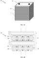
- FIG. 1A is a perspective view of an electrolyzer cell stack 100
- FIG. 1B is a sectional view of a portion of the stack 100, according to various embodiments of the present disclosure.
- the stack 100 may be a solid oxide electrolyzer cell (SOEC) stack that includes solid oxide electrolyzer cells 1 separated by interconnects 10.
- SOEC solid oxide electrolyzer cell
- each electrolyzer cell 1 comprises an air-side electrode 3, a solid oxide electrolyte 5, and a fuel-side electrode 7.
- Electrolyzer cell stacks are frequently built from a multiplicity of electrolyzer cells 1 in the form of planar elements, tubes, or other geometries.
- electrolyzer cell stack 100 in FIG. 1A is vertically oriented, electrolyzer cell stacks may be oriented horizontally or in any other direction.
- water may be provided through water conduits 22 (e.g., water riser openings) formed in each interconnect 10 and electrolyzer cell 1, while oxygen may be provided from the side of the stack between air side ribs of the interconnects 10.
- Each interconnect 10 electrically connects adjacent electrolyzer cells 1 in the stack 100.
- an interconnect 10 may electrically connect the fuel-side electrode 7 of one electrolyzer cell 1 to the air-side electrode 3 of an adjacent electrolyzer cell 1.
- FIG. 1B shows that the lower electrolyzer cell 1 is located between two interconnects 10.
- a Ni mesh (not shown) may be used to electrically connect the interconnect 10 to the fuel-side electrode 7 of an adjacent electrolyzer cell 1.
- Each interconnect 10 includes fuel-side ribs 12A that at least partially define fuel channels 8A and air-side ribs 12B that at least partially define oxidant (e.g., air) channels 8B.
- the interconnect 10 may operate as a separator that separates water flowing to the fuel-side electrode of one cell 1 in the stack from oxygen flowing from the air-side electrode of an adjacent cell 1 in the stack.
- there may be an air end plate or fuel end plate (not shown).
- Each interconnect 10 may be made of or may contain electrically conductive material, such as a metal alloy (e.g., chromium-iron alloy) which has a similar coefficient of thermal expansion to that of the solid oxide electrolyte in the cells (e.g., a difference of 0-10%).
- the interconnects 10 may comprise a metal (e.g., a chromium-iron alloy, such as 4-6 weight percent iron (e.g., 5 wt.% iron), optionally 1 or less weight percent yttrium and balance chromium alloy), and may electrically connect the fuel-side electrode 7 of one electrolyzer cell 1 to the air-side electrode 3 of an adjacent electrolyzer cell 1.
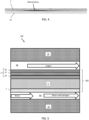
- FIG. 2A is a top view of the air side of the interconnect 10
- FIG. 2B is a top view of a fuel side of the interconnect 10, according to various embodiments of the present disclosure.
- the air side includes the air channels 8B that extend from opposing first and second edges of the interconnect 10. Oxygen flows through the air channels 8B from the air-side electrode 3 of an adjacent electrolyzer cell 1.
- Ring seals 20 may surround fuel holes 22A, 22B of the interconnect 10, to prevent water from contacting the air-side electrode 3.
- Strip-shaped peripheral seals 24 are located on peripheral portions of the air side of the interconnect 10.
- the seals 20, 24 may be formed of a glass or glass-ceramic material.
- the peripheral portions may be an elevated plateau which does not include ribs or channels.
- the surface of the peripheral regions may be coplanar with tops of the ribs 12B.
- the fuel side of the interconnect 10 may include the fuel channels 8A and fuel manifolds 28.
- a frame seal 26 is disposed on a peripheral region of the fuel side of the interconnect 10.
- the peripheral region may be an elevated plateau which does not include ribs or channels.
- the surface of the peripheral region may be coplanar with tops of the ribs 12A.
- FIG. 3A is a plan view of the air side of the electrolyzer cell 1
- FIG. 3B is a plan view of the fuel side of the electrolyzer cell 1, according to various embodiments of the present disclosure.
- the electrolyzer cell 1 may include an inlet fuel hole 22A, an outlet fuel hole 22B, the electrolyte 5, and the air-side electrode 3.
- the air-side electrode 3 may be disposed on the air side of the electrolyte 5.
- the fuel-side electrode 7 may be disposed on an opposing fuel (e.g., water) side of the electrolyte 5.
- the fuel holes 22A, 22B may extend through the electrolyte 5 and may be arranged to overlap with the fuel holes 22A, 22B of the interconnects 10, when assembled in the electrolyzer cell stack 100.
- the air-side electrode 3 may be printed on the electrolyte 5 so as not to overlap with the ring seals 20 and the peripheral seals 24 when assembled in the electrolyzer cell stack 100.
- the fuel-side electrode 7 may have a similar shape as the air-side electrode 3.
- the fuel-side electrode 7 may be disposed so as not to overlap with the frame seal 26, when assembled in the stack 100. In other words, the electrodes 3 and 7 may be recessed from the edges of the electrolyte 5, such that corresponding edge regions of the electrolyte 5 may directly contact the corresponding seals 20, 24, 26.
- the electrolyzer cell stack 100 may only be operated in the electrolysis mode. Thus the electrolyzer cell stack 100 is not operated in a fuel cell mode to generate power from a fuel and air provided to fuel-side and air-side electrodes, respectively.
- the electrolyzer cell stack 100 may comprise a solid oxide regenerative (i.e., reversible) fuel cell (SORFC) stack.
- SORFCs can be operated in a fuel cell (FC) mode (e.g., power generation mode), in order to generate electricity from fuel and air provided to fuel-side and air-side electrodes, respectively, and may be operated in an electrolyzer cell (EC) mode (e.g., electrolysis mode) in order to produce hydrogen and oxygen from water provided to the fuel-side electrode 7.
- FC fuel cell
- EC electrolyzer cell
- oxygen ions are transported from the air-side (e.g., cathode) electrode 3 to the fuel-side (e.g., anode) electrode 7 of the SORFC to oxidize the fuel (e.g., hydrogen and/or hydrocarbon fuel, such as natural gas) and to generate electricity.
- the fuel e.g., hydrogen and/or hydrocarbon fuel, such as natural gas
- EC mode a positive potential is applied to the air side of the cell, and the oxygen ions are transported from the water at the fuel-side electrode 7 through the electrolyte 5 to the air-side electrode 3.
- water is electrolyzed into hydrogen at the fuel-side electrode 7 and oxygen at air-side electrode 3.
- the air-side electrode 3 and the fuel-side electrode 7 of a SORFC respectively operate as a cathode and an anode during FC mode, and respectively operate as an anode and a cathode during EC mode (i.e., a FC mode cathode is an EC mode anode, and a FC mode anode is an EC mode cathode).
- a FC mode cathode is an EC mode anode
- FC mode anode is an EC mode cathode
- the open circuit voltage for a SORFC operating with air and wet fuel may be from about 0.9 to 1.0V (depending on water content)
- the positive voltage applied to the air-side electrode in EC mode increases the cell voltage to typical operating voltages of from about 1.1 to 1.3V.
- the cell voltages may increase over time if there is degradation of the cell, which may result from both ohmic sources and electrode polarization.
- FIG. 4 is a photograph showing air electrode 3 delamination after operating a solid oxide electrolyzer cell in electrolysis mode for an extended time at a high current density. As shown in FIG. 4 , the air-side electrode 3 may separate from the underlying electrolyte 5, as indicated by the black area there between.
- FIG. 5 is a cross-sectional view of an electrolyzer cell stack 500 including an electrolysis-tolerant solid oxide electrolyzer cell 502, according to various embodiments of the present disclosure.
- the electrolyzer cell stack 500 is similar to the stack 100 of FIGS. 1A-3B . As such, only the differences there between will be discussed in detail.
- the electrolyzer cell stack 500 may include at least one electrolyzer cell 502 disposed between interconnects 10.
- the electrolyzer cell 502 may operate only in the electrolysis mode (e.g., the cell may comprise a solid oxide electrolyzer cell (SOEC)), or may operate in both fuel cell and electrolysis modes (e.g., the electrolyzer cell 502 may comprise a SORFC).
- the electrolyzer cell 502 includes a solid oxide electrolyte 5, an air-side electrode 3 disposed on an air side of the electrolyte 5, and a fuel-side electrode 7 disposed on a fuel side of the electrolyte 5.
- Air may be provided to the air-side electrode 3 by air channels 8B in a fuel cell mode, and fuel may be provided to the fuel-side electrode 7 by fuel channels 8A in the fuel cell mode, while water may be provided to the fuel-side electrode 7 by fuel channels 8A in the electrolysis mode.
- the electrolyte 5 may include an ionically conductive material or phase, such as a stabilized zirconia, for example scandia-stabilized zirconia (SSZ), yttria-stabilized zirconia (YSZ), scandia-ceria-stabilized zirconia (SCSZ), scandia-ceria-yttria-stabilized zirconia (SCYSZ), scandia-ceria-ytterbia-stabilized zirconia (SCYbSZ), or the like.
- SSZ scandia-stabilized zirconia
- YSZ yttria-stabilized zirconia
- SCSZ scandia-ceria-stabilized zirconia
- SCYSZ scandia-ceria-yttria-stabilized zirconia
- SCYbSZ scandia-ceria-ytterbia-stabilized zirconia
- the electrolyte 5 may comprise another ionically conductive material, such as a doped ceria, for example samaria-doped ceria (SDC), gadolinia-doped ceria (GDC), or yttria-doped ceria (YDC).
- a doped ceria for example samaria-doped ceria (SDC), gadolinia-doped ceria (GDC), or yttria-doped ceria (YDC).
- the electrolyte 5 may comprise (ZrO 2 ) 0.88 (Sc 2 O 3 ) 0.1 (CeO 2 ) 0.01 (Yb 2 O 3 ) 0.01 or (ZrO 2 ) 0.88 (Sc 2 O 3 ) 0.1 (CeO 2 ) 0.01 (Y 2 O 3 ) 0.01 .
- the electrolyte 5 may comprise (ZrO 2 ) 0.89 (Sc 2 O 3 ) 0.1 (CeO 2 ) 0.01 .
- the fuel-side electrode 7 may comprise a cermet layer comprising a metal-containing phase and a ceramic phase.
- the metal-containing phase may include a metal catalyst, such as nickel (Ni), cobalt (Co), copper (Cu), alloys thereof, or the like, which operates as an electron conductor.
- the metal catalyst may be in a metallic state or may be in an oxide state.
- the metal catalyst forms a metal oxide when it is in an oxidized state.
- the fuel-side electrode 7 may be annealed in a reducing atmosphere prior to operation of the electrolyzer cell 1, to reduce the oxidized metal catalyst to a metallic state.
- the metal-containing phase may consist entirely of nickel in a reduced state. This nickel-containing phase may form nickel oxide when it is in an oxidized state.
- the fuel-side electrode 7 is preferably annealed in a reducing atmosphere prior to operation to reduce the nickel oxide to nickel.
- the ceramic phase of the fuel-side electrode 7 may include, but is not limited to gadolinia-doped ceria (GDC), samaria-doped ceria (SDC), ytterbia-doped ceria (YDC), scandia-stabilized zirconia (SSZ), ytterbia-ceria-scandia-stabilized zirconia (YbCSSZ), or the like.
- GDC gadolinia-doped ceria
- SDC samaria-doped ceria
- YDC ytterbia-doped ceria
- SSZ scandia-stabilized zirconia
- YbCSSZ ytterbia-ceria-scandia-stabilized zirconia
- scandia may be present in an amount equal to 9 to 11 mol %, such as 10 mol %
- ceria may present in amount greater than 0 (e.g., at least 0.5 mol %) and equal to or less than 2.5 mol %, such as 1 mol %
- at least one of yttria and ytterbia may be present in an amount greater than 0 and equal to or less than 2.5 mol %, such as 1 mol %, as disclosed in U.S. Pat. No. 8,580,456 , which is incorporated herein, by reference.
- an additional contact or current collector layer may be placed over the fuel-side electrodes 7.
- a Ni or nickel oxide anode contact layer may be formed on the fuel-side electrode 7.
- the air-side electrode 3 may include a barrier layer 30 disposed directly on an air side of the electrolyte 5, a functional layer 32 disposed on the barrier layer 30, and an optional current collector layer 34 disposed on the functional layer 32.
- the functional layer 32 is located between the barrier layer 30 and the current collector layer 34.
- the barrier layer 30 may be sintered to the air side of the electrolyte 5.
- the barrier layer 30 may comprise, consist essentially or, or consist of a doped ceria material.
- the barrier layer may comprise from about 95 weight percent (wt.%) to about 100 wt.% of the doped ceria material, based on the total weight of the barrier layer 30.
- the doped ceria material may include samarium-doped ceria (SDC) and/or gadolinium-doped ceria (GDC).
- the SDC may be represented by the formula: Ce 1-x Sm x O 2-d , where x ranges from 0.1 to 0.3.
- specific SDC materials may be represented by the formulas: Ce 0.8 Sm 0.2 O 2-d , Ce 0.9 Sm 0.1 O 2-d , and Ce 0.7 Sm 0.3 O 2-d , where d ranges from 0 to 0.2, such as from 0 to 0.1.
- the GDC may be represented by the formula Ce 1-x Gd x O 2-d , where x ranges from 0.1 to 0.3 and d ranges from 0 to 0.2, such as from 0 to 0.1.
- specific GDC materials may be represented by the formulas: Ce 0.9 Gd 0.1 O 2-d , Ce 0.8 Gd 0.2 O 2-d , and Ce 0.7 Gd 0.3 O 2-d , where d ranges from 0 to 0.2, such as from 0 to 0.1.
- the functional layer 32 may include a mixture of an electrically conductive material and the doped ceria material.
- the electrically conductive material may comprise an electrically conductive perovskite material, such as lanthanum strontium manganite (LSM), lanthanum strontium cobalt ferrite (LSCF), lanthanum strontium cobaltite (LSC), lanthanum strontium cobalt manganite (LSCM), lanthanum strontium ferrite (LSF), La 0.85 Sr 0.15 Cr 0.9 Ni 0.1 O 3 (LSCN), combinations thereof, or the like.
- the electrically conductive material may preferably comprise LSM and/or LSCF.
- the electrically conductive material may comprise a metal, such as platinum.
- the functional layer 32 may include from about 10 wt.% to about 90 wt.% of the electrically conductive material described above, and from about 10 wt.% to about 90 wt.% of the doped ceria material.
- the functional layer may include the LSM as the electrically conductive material.
- the LSM may be represented by the formula: (La 1-z Sr z ) q MnO 3-d , wherein z ranges from 0.1 to 0.4, q ranges from 0.94 to 1, such as 0.96 to 1, and d ranges from 0 to 0.2.
- the LSM may comprise La 0.8 Sr 0.2 MnO 3-d or A-site deficient LSM, such as (La 0.8 Sr 0.2 ) 0.98 MnO 3-d , wherein d ranges from 0 to 0.1.
- the functional layer may include the LSCF as the electrically conductive material.
- the LSCF may be represented by the formula: (La x Sr 1-x ) y Co z Fe 1-z O 3- ⁇ , wherein x ranges from 0.4 to 0.8, y ranges from 0.94 to 1.0, z ranges from 0.01 to 0.99, and ⁇ is the equilibrium oxygen deficiency which ranges from 0 to 0.1.
- the LSCF may comprise La 0.58 Sr 0.4 Co 0.2 Fe 0.8 O 3- ⁇ , (La 0.6 Sr 0.4 ) 0.98 Co 0.2 Fe 0.8 O 3- ⁇ , or (La 0.6 Sr 0.4 ) 0.95 Co 0.2 Fe 0.8 O 3- ⁇ , where ⁇ is the equilibrium oxygen deficiency.
- the barrier layer 30 and the functional layer 32 may include the same doped ceria material or different doped ceria materials.
- the barrier layer 30 may include GDC and the functional layer 32 may include LSM and GDC, or LSM and SDC.
- the barrier layer 30 may include SDC and the functional layer 32 may include LSM and SDC, or LSM and GDC.
- the barrier layer may include SDC and the functional layer may include LSCF and SDC, or LSCF and GDC.
- the mixed oxide-ion and electronic conduction of the ceria phases of the barrier layer 30 reduces the overpotential at the interface between the barrier layer 30 and the functional layer 32.
- the reduction in overpotential may suppress the air-side electrode 3 delamination from the electrolyte 5.
- the current collector layer 34 may include an electrically conductive material, such as an electrically conductive metal oxide, such as LSM.
- an electrically conductive metal oxide such as LSM.
- other conductive perovskites such as LSC, LSCM, LSCF, LSF, LSCN, etc., or metals, such as Pt, may also be used.
- FIG. 6A is a chart showing a voltage change of first embodiment SOEC cells and second embodiment SOEC cells, between beginning of life and 17 current cycles of operation in an embodiment SOEC stack.
- FIG. 6B is a chart showing the voltage change of comparative SOEC cells between beginning of life and 17 current cycles of operation in a comparative SOEC stack, under similar conditions.
- the y-axis in both figures is the voltage change in volts, and the x-axis is a number of the SOEC cell in the respective stack.
- the first and second embodiment SOEC cells have similar configurations, except that the first embodiment SOEC cells contain SDC barrier layers 30 and GDC / LSM cathode functional layers 32, while the second embodiment SOEC cells contain SDC barrier layers 30 and SDC / LSM cathode functional layers 32.
- the comparative SOEC cells include no barrier layers 30 and cathode functional layers that comprise YSZ / LSM.
- the comparative SOEC cells experience higher cell voltage differences (and thus an increase in cell over-potential), while the embodiment cells exhibit substantially lower cell voltage differences. Accordingly, the doped ceria-based barrier layer and cathode functional layer materials provide an unexpectedly improved protection against cell over-potential, which is expected to decrease delamination and/or general cathode degradation.
Landscapes
- Chemical & Material Sciences (AREA)
- Engineering & Computer Science (AREA)
- Chemical Kinetics & Catalysis (AREA)
- Electrochemistry (AREA)
- Materials Engineering (AREA)
- Metallurgy (AREA)
- Organic Chemistry (AREA)
- Inorganic Chemistry (AREA)
- Manufacturing & Machinery (AREA)
- Sustainable Energy (AREA)
- Life Sciences & Earth Sciences (AREA)
- Sustainable Development (AREA)
- General Chemical & Material Sciences (AREA)
- Ceramic Engineering (AREA)
- Electrolytic Production Of Non-Metals, Compounds, Apparatuses Therefor (AREA)
- Inert Electrodes (AREA)
- Fuel Cell (AREA)
- Electrodes For Compound Or Non-Metal Manufacture (AREA)
Applications Claiming Priority (1)
| Application Number | Priority Date | Filing Date | Title |
|---|---|---|---|
| US17/519,996 US12460308B2 (en) | 2021-11-05 | 2021-11-05 | Solid oxide electrolyzer cell including electrolysis-tolerant air-side electrode |
Publications (1)
| Publication Number | Publication Date |
|---|---|
| EP4177381A1 true EP4177381A1 (de) | 2023-05-10 |
Family
ID=84245741
Family Applications (1)
| Application Number | Title | Priority Date | Filing Date |
|---|---|---|---|
| EP22205645.9A Pending EP4177381A1 (de) | 2021-11-05 | 2022-11-04 | Festoxidelektrolysezelle mit elektrolysetoleranter luftseitiger elektrode |
Country Status (7)
| Country | Link |
|---|---|
| US (2) | US12460308B2 (de) |
| EP (1) | EP4177381A1 (de) |
| JP (1) | JP2023070100A (de) |
| KR (1) | KR20230066251A (de) |
| CN (1) | CN116093389A (de) |
| CA (1) | CA3179069A1 (de) |
| TW (1) | TW202328499A (de) |
Families Citing this family (1)
| Publication number | Priority date | Publication date | Assignee | Title |
|---|---|---|---|---|
| CN119437575B (zh) * | 2024-07-30 | 2025-12-02 | 中国科学技术大学 | 固体氧化物电池的气密性检测装置 |
Citations (3)
| Publication number | Priority date | Publication date | Assignee | Title |
|---|---|---|---|---|
| US20060166070A1 (en) * | 2003-09-10 | 2006-07-27 | Ion America Corporation | Solid oxide reversible fuel cell with improved electrode composition |
| US8580456B2 (en) | 2010-01-26 | 2013-11-12 | Bloom Energy Corporation | Phase stable doped zirconia electrolyte compositions with low degradation |
| CN112663079A (zh) * | 2020-12-04 | 2021-04-16 | 中国科学院大连化学物理研究所 | 一种管状固体氧化物电解池及其制备方法与应用 |
Family Cites Families (31)
| Publication number | Priority date | Publication date | Assignee | Title |
|---|---|---|---|---|
| US6854688B2 (en) | 2002-05-03 | 2005-02-15 | Ion America Corporation | Solid oxide regenerative fuel cell for airplane power generation and storage |
| US6821663B2 (en) | 2002-10-23 | 2004-11-23 | Ion America Corporation | Solid oxide regenerative fuel cell |
| US7045238B2 (en) | 2003-03-24 | 2006-05-16 | Ion America Corporation | SORFC power and oxygen generation method and system |
| US6924053B2 (en) | 2003-03-24 | 2005-08-02 | Ion America Corporation | Solid oxide regenerative fuel cell with selective anode tail gas circulation |
| US7575822B2 (en) | 2003-04-09 | 2009-08-18 | Bloom Energy Corporation | Method of optimizing operating efficiency of fuel cells |
| US7364810B2 (en) | 2003-09-03 | 2008-04-29 | Bloom Energy Corporation | Combined energy storage and fuel generation with reversible fuel cells |
| US7150927B2 (en) | 2003-09-10 | 2006-12-19 | Bloom Energy Corporation | SORFC system with non-noble metal electrode compositions |
| JP4849774B2 (ja) * | 2004-01-30 | 2012-01-11 | 京セラ株式会社 | 固体電解質形燃料電池セル及び固体電解質形燃料電池 |
| US20060216575A1 (en) | 2005-03-23 | 2006-09-28 | Ion America Corporation | Perovskite materials with combined Pr, La, Sr, "A" site doping for improved cathode durability |
| US7951509B2 (en) | 2006-04-03 | 2011-05-31 | Bloom Energy Corporation | Compliant cathode contact materials |
| WO2008094550A1 (en) | 2007-01-31 | 2008-08-07 | Bloom Energy Corporation | Fuel cell stack components |
| EP2662917A1 (de) * | 2007-08-31 | 2013-11-13 | Technical University of Denmark | Anodenunterstützte Festoxidbrennstoffzelle |
| US8293412B2 (en) | 2007-11-20 | 2012-10-23 | Bloom Energy Corporation | Enhanced efficiency of a combined SORFC energy storage and fuel generation system |
| JP5481611B2 (ja) * | 2008-04-28 | 2014-04-23 | 国立大学法人山梨大学 | 高温水蒸気電解セル |
| CN102217130A (zh) | 2008-11-21 | 2011-10-12 | 博隆能源股份有限公司 | 用于生产燃料电池组件的涂覆工艺 |
| CN103155255B (zh) | 2010-08-17 | 2015-09-30 | 博隆能源股份有限公司 | 固态氧化物燃料电池的制造方法 |
| FR2969179B1 (fr) | 2010-12-20 | 2013-02-08 | Commissariat Energie Atomique | Cellule de production d'hydrogene comprenant une cellule d'electrolyseur de la vapeur d'eau a haute temperature. |
| JP5838113B2 (ja) | 2011-03-30 | 2015-12-24 | 株式会社日本触媒 | 固体酸化物形燃料電池用電解質シートと、それを備えた固体酸化物形燃料電池用単セルおよび固体酸化物形燃料電池、並びに、固体酸化物形燃料電池用電解質シートの検査方法および固体酸化物形燃料電池用電解質シートの製造方法 |
| WO2013013677A1 (en) | 2011-07-22 | 2013-01-31 | Danmarks Tekniske Universitet | A method for the densification of ceramic layers, especially ceramic layers within solid oxide cell (soc) technology, and products obtained by the method |
| TWI552417B (zh) | 2011-11-17 | 2016-10-01 | 博隆能源股份有限公司 | 對氧化鋯為主之電解質提供抗腐蝕性之多層塗層 |
| US10431833B2 (en) | 2012-03-01 | 2019-10-01 | Bloom Energy Corporation | Coatings for metal interconnects to reduce SOFC degradation |
| WO2014186126A1 (en) | 2013-05-16 | 2014-11-20 | Bloom Energy Corporation | Corrosion resistant barrier layer for a solid oxide fuel cell stack and method of making thereof |
| WO2016077235A1 (en) | 2014-11-12 | 2016-05-19 | Bloom Energy Corporation | Sofc cathode compositions with improved resistance to sofc degradation |
| JP2016157519A (ja) * | 2015-02-23 | 2016-09-01 | 学校法人同志社 | 固体酸化物形燃料電池用燃料極とその製造方法および前記燃料極を含む固体酸化物形燃料電池 |
| CN113089010B (zh) | 2015-07-16 | 2023-09-12 | 住友电气工业株式会社 | 氢制造装置 |
| JP6605969B2 (ja) * | 2016-01-20 | 2019-11-13 | 日本特殊陶業株式会社 | 電気化学反応単セル、インターコネクタ−電気化学反応単セル複合体、および、電気化学反応セルスタック |
| KR101978952B1 (ko) | 2016-12-13 | 2019-08-28 | 한국과학기술연구원 | 반응방지막을 포함하는 고온 고체산화물 셀, 이의 제조방법 |
| JP7194547B2 (ja) * | 2018-10-01 | 2022-12-22 | Dowaエレクトロニクス株式会社 | 複合酸化物粉末 |
| EP3960906A4 (de) * | 2019-04-26 | 2022-06-08 | Panasonic Intellectual Property Management Co., Ltd. | Membran-elektroden-einheit, festoxidbrennstoffzelle und elektrochemische vorrichtung |
| US20220190373A1 (en) | 2020-12-14 | 2022-06-16 | Bloom Energy Corporation | Solid oxide electrolyzer cell including electrolysis-tolerant air-side electrode |
| TW202335111A (zh) | 2022-01-10 | 2023-09-01 | 美商博隆能源股份有限公司 | 用於sofc及soec之電極的優化製備方法 |
-
2021
- 2021-11-05 US US17/519,996 patent/US12460308B2/en active Active
-
2022
- 2022-10-12 CA CA3179069A patent/CA3179069A1/en active Pending
- 2022-10-24 JP JP2022169666A patent/JP2023070100A/ja active Pending
- 2022-10-25 TW TW111140359A patent/TW202328499A/zh unknown
- 2022-10-28 KR KR1020220141209A patent/KR20230066251A/ko active Pending
- 2022-11-02 CN CN202211361699.5A patent/CN116093389A/zh active Pending
- 2022-11-04 EP EP22205645.9A patent/EP4177381A1/de active Pending
-
2025
- 2025-10-15 US US19/359,156 patent/US20260043159A1/en active Pending
Patent Citations (3)
| Publication number | Priority date | Publication date | Assignee | Title |
|---|---|---|---|---|
| US20060166070A1 (en) * | 2003-09-10 | 2006-07-27 | Ion America Corporation | Solid oxide reversible fuel cell with improved electrode composition |
| US8580456B2 (en) | 2010-01-26 | 2013-11-12 | Bloom Energy Corporation | Phase stable doped zirconia electrolyte compositions with low degradation |
| CN112663079A (zh) * | 2020-12-04 | 2021-04-16 | 中国科学院大连化学物理研究所 | 一种管状固体氧化物电解池及其制备方法与应用 |
Non-Patent Citations (2)
| Title |
|---|
| LÓPEZ-ROBLEDO M.J. ET AL: "Reversible operation of microtubular solid oxide cells using La0.6Sr0.4Co0.2Fe0.8O3-[delta]-Ce0.9Gd0.1O2-[delta] oxygen electrodes", JOURNAL OF POWER SOURCES, vol. 378, 1 February 2018 (2018-02-01), AMSTERDAM, NL, pages 184 - 189, XP093036076, ISSN: 0378-7753, DOI: 10.1016/j.jpowsour.2017.12.035 * |
| NECHACHE AZIZ ET AL: "Alternative and innovative solid oxide electrolysis cell materials: A short review", RENEWABLE AND SUSTAINABLE ENERGY REVIEWS, ELSEVIERS SCIENCE, NEW YORK, NY, US, vol. 149, 27 June 2021 (2021-06-27), XP086732169, ISSN: 1364-0321, [retrieved on 20210627], DOI: 10.1016/J.RSER.2021.111322 * |
Also Published As
| Publication number | Publication date |
|---|---|
| CA3179069A1 (en) | 2023-05-05 |
| US20230141938A1 (en) | 2023-05-11 |
| US12460308B2 (en) | 2025-11-04 |
| JP2023070100A (ja) | 2023-05-18 |
| CN116093389A (zh) | 2023-05-09 |
| TW202328499A (zh) | 2023-07-16 |
| US20260043159A1 (en) | 2026-02-12 |
| KR20230066251A (ko) | 2023-05-15 |
Similar Documents
| Publication | Publication Date | Title |
|---|---|---|
| EP3432401B1 (de) | Phasenstabile dotierte zirkonium-elektrolytzusammensetzungen mit geringer zersetzung | |
| US8617763B2 (en) | Internal reforming anode for solid oxide fuel cells | |
| US10593981B2 (en) | Heterogeneous ceramic composite SOFC electrolyte | |
| US20080254336A1 (en) | Composite anode showing low performance loss with time | |
| KR102881977B1 (ko) | 전기분해-내성 공기측 전극을 포함하는 고체 산화물 전해조 전지 | |
| CN107078309A (zh) | 用于燃料电池电极的组合物 | |
| US20260043159A1 (en) | Solid oxide electrolyzer cell including electrolysis-tolerant air-side electrode | |
| US12506158B2 (en) | Optimized processing of electrodes for SOFC and SOEC | |
| US20250230562A1 (en) | Solid oxide electrochemical cell containing strontium getter | |
| WO2025226468A1 (en) | Solid oxide electrochemical cell including ceria-free electrolyte | |
| US11742495B2 (en) | Ni—Fe based cathode functional layers for solid oxide electrochemical cells | |
| TW202610084A (zh) | 包含無氧化鈰電解質之固態氧化物電化學電池 | |
| KR20240085806A (ko) | 고체산화물 셀 및 이의 운전 방법 |
Legal Events
| Date | Code | Title | Description |
|---|---|---|---|
| PUAI | Public reference made under article 153(3) epc to a published international application that has entered the european phase |
Free format text: ORIGINAL CODE: 0009012 |
|
| STAA | Information on the status of an ep patent application or granted ep patent |
Free format text: STATUS: THE APPLICATION HAS BEEN PUBLISHED |
|
| AK | Designated contracting states |
Kind code of ref document: A1 Designated state(s): AL AT BE BG CH CY CZ DE DK EE ES FI FR GB GR HR HU IE IS IT LI LT LU LV MC ME MK MT NL NO PL PT RO RS SE SI SK SM TR |
|
| STAA | Information on the status of an ep patent application or granted ep patent |
Free format text: STATUS: REQUEST FOR EXAMINATION WAS MADE |
|
| 17P | Request for examination filed |
Effective date: 20231106 |
|
| RBV | Designated contracting states (corrected) |
Designated state(s): AL AT BE BG CH CY CZ DE DK EE ES FI FR GB GR HR HU IE IS IT LI LT LU LV MC ME MK MT NL NO PL PT RO RS SE SI SK SM TR |
|
| STAA | Information on the status of an ep patent application or granted ep patent |
Free format text: STATUS: EXAMINATION IS IN PROGRESS |
|
| 17Q | First examination report despatched |
Effective date: 20260213 |