EP4177438B1 - Volet de régulation d'écoulement de fluide de puits - Google Patents
Volet de régulation d'écoulement de fluide de puits Download PDFInfo
- Publication number
- EP4177438B1 EP4177438B1 EP22216234.9A EP22216234A EP4177438B1 EP 4177438 B1 EP4177438 B1 EP 4177438B1 EP 22216234 A EP22216234 A EP 22216234A EP 4177438 B1 EP4177438 B1 EP 4177438B1
- Authority
- EP
- European Patent Office
- Prior art keywords
- flow
- choke
- pressure
- fluid
- closure member
- Prior art date
- Legal status (The legal status is an assumption and is not a legal conclusion. Google has not performed a legal analysis and makes no representation as to the accuracy of the status listed.)
- Active
Links
Images


Classifications
-
- E—FIXED CONSTRUCTIONS
- E21—EARTH OR ROCK DRILLING; MINING
- E21B—EARTH OR ROCK DRILLING; OBTAINING OIL, GAS, WATER, SOLUBLE OR MELTABLE MATERIALS OR A SLURRY OF MINERALS FROM WELLS
- E21B34/00—Valve arrangements for boreholes or wells
- E21B34/06—Valve arrangements for boreholes or wells in wells
- E21B34/08—Valve arrangements for boreholes or wells in wells responsive to flow or pressure of the fluid obtained
-
- E—FIXED CONSTRUCTIONS
- E21—EARTH OR ROCK DRILLING; MINING
- E21B—EARTH OR ROCK DRILLING; OBTAINING OIL, GAS, WATER, SOLUBLE OR MELTABLE MATERIALS OR A SLURRY OF MINERALS FROM WELLS
- E21B21/00—Methods or apparatus for flushing boreholes, e.g. by use of exhaust air from motor
- E21B21/08—Controlling or monitoring pressure or flow of drilling fluid, e.g. automatic filling of boreholes, automatic control of bottom pressure
-
- E—FIXED CONSTRUCTIONS
- E21—EARTH OR ROCK DRILLING; MINING
- E21B—EARTH OR ROCK DRILLING; OBTAINING OIL, GAS, WATER, SOLUBLE OR MELTABLE MATERIALS OR A SLURRY OF MINERALS FROM WELLS
- E21B21/00—Methods or apparatus for flushing boreholes, e.g. by use of exhaust air from motor
- E21B21/10—Valve arrangements in drilling-fluid circulation systems
- E21B21/106—Valve arrangements outside the borehole, e.g. kelly valves
-
- E—FIXED CONSTRUCTIONS
- E21—EARTH OR ROCK DRILLING; MINING
- E21B—EARTH OR ROCK DRILLING; OBTAINING OIL, GAS, WATER, SOLUBLE OR MELTABLE MATERIALS OR A SLURRY OF MINERALS FROM WELLS
- E21B34/00—Valve arrangements for boreholes or wells
- E21B34/02—Valve arrangements for boreholes or wells in well heads
- E21B34/025—Chokes or valves in wellheads and sub-sea wellheads for variably regulating fluid flow
-
- E—FIXED CONSTRUCTIONS
- E21—EARTH OR ROCK DRILLING; MINING
- E21B—EARTH OR ROCK DRILLING; OBTAINING OIL, GAS, WATER, SOLUBLE OR MELTABLE MATERIALS OR A SLURRY OF MINERALS FROM WELLS
- E21B44/00—Automatic control systems specially adapted for drilling operations, i.e. self-operating systems which function to carry out or modify a drilling operation without intervention of a human operator, e.g. computer-controlled drilling systems; Systems specially adapted for monitoring a plurality of drilling variables or conditions
- E21B44/005—Below-ground automatic control systems
-
- E—FIXED CONSTRUCTIONS
- E21—EARTH OR ROCK DRILLING; MINING
- E21B—EARTH OR ROCK DRILLING; OBTAINING OIL, GAS, WATER, SOLUBLE OR MELTABLE MATERIALS OR A SLURRY OF MINERALS FROM WELLS
- E21B47/00—Survey of boreholes or wells
- E21B47/06—Measuring temperature or pressure
-
- E—FIXED CONSTRUCTIONS
- E21—EARTH OR ROCK DRILLING; MINING
- E21B—EARTH OR ROCK DRILLING; OBTAINING OIL, GAS, WATER, SOLUBLE OR MELTABLE MATERIALS OR A SLURRY OF MINERALS FROM WELLS
- E21B47/00—Survey of boreholes or wells
- E21B47/10—Locating fluid leaks, intrusions or movements
-
- E—FIXED CONSTRUCTIONS
- E21—EARTH OR ROCK DRILLING; MINING
- E21B—EARTH OR ROCK DRILLING; OBTAINING OIL, GAS, WATER, SOLUBLE OR MELTABLE MATERIALS OR A SLURRY OF MINERALS FROM WELLS
- E21B47/00—Survey of boreholes or wells
- E21B47/10—Locating fluid leaks, intrusions or movements
- E21B47/117—Detecting leaks, e.g. from tubing, by pressure testing
Definitions
- This disclosure relates generally to equipment utilized and operations performed in conjunction with a subterranean well and, in an example described below, more particularly provides for well fluid flow control with a remotely controlled flow choke.
- a flow choke can be used in well drilling operations to variably restrict flow of a well fluid.
- the flow choke can be used to regulate pressure in a wellbore by variably restricting flow of well fluid from an annulus formed between a drill string and the wellbore.
- CA 2369574 A1 discloses in a sub-sea wellhead insert-type choke valve having a bonnet, a pair of pressure transmitters mounted in the bonnet.
- One transmitter is connected by a passageway with the annular clearance between the cartridge of the insert assembly and the valve body. This transmitter measures the pressure of the fluid in the clearance and transmits signals indicative thereof to a receiver at surface.
- the other transmitter is connected by a passageway with the fluid in the valve outlet, measures the pressure of this fluid and transmits signals indicative thereof to the receiver. In this way the high and low pressures upstream and downstream of the choke valve flow trim are monitored by transmitters, which can be serviced by bringing the insert assembly to surface.
- US 2011/240298 A1 discloses a wellhead valve system for adjusting the flow, for example, of hydrocarbon, comprising a hydraulic control valve for opening the wellhead made up of a valve body provided with a pipe for the passage of a flow of fluids, having an inlet opening and an outlet opening, interposed between the inlet opening and the outlet opening being an adjustable orifice; an actuator adapted to command the valve to close and open, in which the actuator operates on opening and closing means of the adjustable orifice; and a position gauge adapted to determine the degree of opening of the adjustable orifice, and is characterized in that the position gauge is integral with the opening and closing means of the adjustable orifice.
- the position gauge Thanks to the accurate measurements carried out by the position gauge, it is possible to determine the gas/liquid monophase and/or biphase flow rate value accurately and instantly, based upon data measured by a plurality of fluid and/or flow parameters sensors, comprising pressure sensors and temperature sensors, preferably positioned integrally with the valve body.
- a closed system may be provided by use of equipment variously known to those skilled in the art as a rotating control device (RCD), rotating control head, rotating drilling head, rotating diverter, pressure control device (PCD), rotating blowout preventer (RBOP), etc.
- RCD rotating control device
- PCD pressure control device
- RBOP rotating blowout preventer
- Such equipment isolates the wellbore 12 from the atmosphere at surface by sealing off the annulus 22, thereby facilitating pressure control in the wellbore.
- the wellbore 12 may be isolated from the atmosphere at surface during well control situations, and not necessarily during drilling operations.
- restriction to flow of the well fluid through the flow choke can be decreased in order to decrease pressure in the annulus, and the restriction to flow through the flow choke can be increased in order to increase pressure in the annulus.
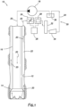
- a control system 26 can be used to operate the flow choke 24 in a manner that maintains a desired pressure in the wellbore 12.
- the control system 26 can include, for example, a programmable logic controller (PLC) that operates the flow choke 24 so that a desired volumetric or mass flow rate of the well fluid 20 through the flow choke is maintained, so that a desired pressure is maintained in the annulus 22 at the surface, so that a desired pressure is maintained at one or more selected locations in the wellbore 12, or so that another desired objective or combination of objectives is obtained or maintained.
- PLC programmable logic controller
- the PLC could control operation of the flow choke 24 using a proportional-integral-derivative (PID) algorithm.
- the control system 26 may include various configurations of processors, static or volatile memory, input devices, output devices, remote communication devices, software, hardware, firmware, etc.
- the scope of this disclosure is not limited to any particular components or combination of components in the control system 26, or to use of a PLC controller or PID algorithm.
- the flow choke 24 includes a flow passage 38 formed through a body 40 of the flow choke.
- the body 40 includes inlet and outlet flanged connections 40a,b for connecting the flow choke 24 between the annulus 22 (e.g., at a wellhead or RCD, not shown in FIG. 1 ) and the flow meter 28 in the system 10.
- the flow choke 24 could be connected between other components.
- a flow restrictor 42 variably restricts flow of the fluid 20 through the flow passage 38.
- the flow restrictor 42 includes a gate or other closure member 44 that is displaceable relative to a flow orifice, bean or seat 46 that encircles the flow passage 38.
- Other types of variable flow restrictors may be used in other examples.
- a flow area A between the closure member 44 and the seat 46 can be varied by displacing the closure member longitudinally relative to the seat. As depicted in FIG. 2 , downward displacement of the closure member 44 relative to the seat 46 (along a longitudinal axis 48) will decrease the flow area A , and subsequent upward displacement of the closure member will increase the flow area.
- the closure member 44 is displaceable by means of an actuator 50 connected to the body 40.
- the actuator 50 displaces a thrust rod or stem 52 connected to the closure member 44, to thereby vary the flow area A between the closure member and the seat 46.
- the actuator 50 in this example comprises a linear actuator that displaces the stem 52 along the longitudinal axis 48.
- the actuator 50 could comprise an axially aligned annular hydraulic motor with planetary gearing, and with a body of the actuator being directly connected to the flow choke body 40.
- the scope of this disclosure is not limited to any particular type of actuator used to operate the flow restrictor 42. In other examples, other types of electrical, hydraulic, pneumatic, etc., actuators or combinations thereof may be used.
- the actuator 50 is connected to the control system 26, so that operation of the actuator 50 (and, thus, the flow restrictor 42 and flow choke 24) is controlled by the control system.
- the restriction to flow of the fluid 20 through the flow restrictor 42 can be varied by the control system 26 to obtain or maintain any of the desired objectives mentioned above.
- the scope of this disclosure is not limited to any particular objective accomplished by operation of the flow restrictor 42 by the control system 26.
- the ports 56a-c are depicted in FIG. 2 as including conventional tubing connectors, but other types of connectors may be used in other examples.
- the sensors 54a-c may be connected directly to the body 40, without use of separate connectors (for example, by threading the sensors into the body at the ports 56a-c).
- the scope of this disclosure is not limited to use of any particular type of connector with the ports 56a-c, or to use of separate connectors at all.
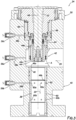
- the flow choke 24 is in a fully open configuration.
- the closure member 44 is displaced to its maximum upward stroke extent, so that a longitudinal distance between the closure member and the seat 46 is at a maximum, and the flow area A is at a maximum. Relatively unrestricted flow of the fluid 20 through the flow passage 38 is permitted in this fully open configuration.
- FIG. 3 a somewhat enlarged scale cross-sectional view of a portion of the flow choke 24 in the open configuration is representatively illustrated. In this view, components of the flow choke 24 may be more clearly seen.
- the external port 56a is in fluid communication with the flow passage 38 upstream of the flow restrictor 42 (relative to a direction of flow of the fluid 20) by means of a fluid line 58a extending through the body 40.
- the external port 56b is in fluid communication with the flow passage 38 downstream of the flow restrictor 42 (relative to the direction of flow of the fluid 20) by means of a fluid line 58b extending through the body 40.
- the sensors 54a,b (see FIG. 2 ) connected to the respective external ports 56a,b can be used to measure fluid pressure in the flow passage 38 respectively upstream and downstream of the flow restrictor 42. A difference between these measured fluid pressures is a pressure differential across the flow restrictor 42.
- a single pressure differential sensor (not shown) connected to both of the external ports 56a,b could be used to directly measure the pressure differential.
- the measured pressure differential can be used to determine a flow rate of the fluid 20 through the flow choke 24, for example, as a "check” or verification of the flow rate measurements output by the flow meter 28 (see FIG. 1 ), or in the event of malfunction of the flow meter 28 or inaccuracies in its measurements (for example, due to excessive two-phase flow through the flow meter).
- a previously empirically determined flow coefficient or flow factor for the flow choke 24 may be used to calculate the flow rate of the fluid 20, based on the measured pressure differential.
- Cv Q * SG / ⁇ P 1 / 2 in which Q is the volumetric flow rate in US gallons per minute, SG is the specific gravity of the fluid 20, and ⁇ P is the differential pressure in pounds per square inch.
- the flow rate calculation may be performed by the control system 26 in this example.
- the calculated flow rate may be used by the control system 26 to directly control operation of the flow choke 24 (such as, by varying the flow restriction to obtain and maintain a desired flow rate set point), or the calculated flow rate may be used in further calculations (for example, to obtain and maintain a desired pressure in the wellbore 12).
- the scope of this disclosure is not limited to any particular use for the calculated flow rate through the flow choke 24. Calculation of the flow rate may not be necessary or may not be performed in other examples.
- the closure member 44 can be displaced by the actuator stem 52 into contact with a sealing surface 46a on the seat 46.
- Another sealing surface 46b is formed on an opposite end of the seat 46, so that the seat can be reversed in the flow choke 24, in the event that the sealing surface 46a becomes damaged, eroded or otherwise unable to function satisfactorily in sealingly engaging the closure member 44.
- the closure member 44 can be displaced by the actuator stem 52 into contact with the sealing surface 46b.
- the closure member 44 is also reversible. Near one end, the closure member 44 has a sealing surface 44a for engagement with the sealing surface 46a or 46b of the seat 46. Another sealing surface 44b is formed near an opposite end of the closure member 44, so that the closure member can be reversed in the flow choke 24, in the event that the sealing surface 44a becomes damaged, eroded or otherwise unable to function satisfactorily in sealingly engaging the seat 46.
- the fluid line 58b is in communication with the flow passage 38 via openings 60a formed through a sleeve 60 positioned in the body 40.
- the sleeve 60 provides erosion resistance about the flow passage 38 downstream of the seat 46.
- An annular recess 62 in the body 40 enables the fluid line 58b to communicate with all of the openings 60a circumferentially about the sleeve 60.
- the sleeve 60 is reversible in the body 40, so that the fluid line 58b can communicate with the flow passage via openings 60b formed through the sleeve near an opposite end of the sleeve.
- a seal 64 (depicted in FIG. 3 as a stack of V- or chevron-type packing) sealingly engages an exterior surface of the stem 52.
- the seal 64 is preferably suitable to isolate an interior of the actuator 50 from the fluid 20 in the flow passage 38 (e.g., with a pressure rating appropriate to resist the fluid pressure in the flow passage).
- the fluid 20 will accumulate in an annular chamber 66 formed radially between the stem 52 and an adapter 68 used to interface the actuator 50 with the valve body 40.
- the fluid line 58c is in communication with the chamber 66, and so the sensor 54c (connected to the external port 56c, see FIG. 2 ) can detect if the fluid 20 has leaked past the seal 64.
- the control system 26 may record data corresponding to the leak event (e.g., time, level, pressure, etc.), provide an indication that the seal 64 requires service, and/or provide an alarm (such as, a visual, audible, textual and/or tactile alarm).
- the leak event e.g., time, level, pressure, etc.
- an alarm such as, a visual, audible, textual and/or tactile alarm.
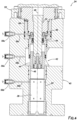
- the flow choke 24 is representatively illustrated in the closed configuration.
- flow of the fluid 20 through the passage 38 is completely prevented, due to sealing engagement between the closure member 44 and the seat 46.
- engagement between the closure member 44 and the seat 46 may result in substantially complete (but not entirely complete) prevention of flow through the flow restrictor 42.
- engagement between the closure member 44 and the seat 46 may result in maximum resistance to flow through the passage 38, and a separate shutoff valve may be used when complete prevention of flow is desired.
- closure member 44 and the seat 46 engage with engagement between the closure member 44 and the seat 46 . In some examples, there may be no direct contact between the closure member 44 and the seat 46 when maximum resistance to flow through the flow choke 24 is achieved. In addition, if the flow restrictor 42 is of another type, the closure member 44 and seat 46 may not be used. Thus, the scope of this disclosure is not limited to any particular configuration, combination or manner of operation of components in the flow restrictor 42.
- FIG. 6 A more detailed view of the flow restrictor 42 in the closed configuration is representatively illustrated in FIG. 6 , and is described more fully below.
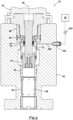
- FIG. 5 another cross-sectional view of the flow choke 24 is representatively illustrated.
- the view depicted in FIG. 5 is rotationally offset (rotated about the longitudinal axis 48) relative to the view depicted in FIG. 4 , so that another external port 56d in the body 40 is visible.
- the external port 56d is in fluid communication via a fluid line 58d with an annular chamber 70 formed radially between the body 40 and the adapter 68.
- the chamber 70 is isolated from the passage 38 by one or more seals 72.
- the fluid 20 will accumulate in the annular chamber 70.
- the fluid line 58d is in communication with the chamber 70, and so a sensor 54d connected to the external port 56d can detect if the fluid 20 has leaked past the seals 72.
- the sensor 54d may be the same as, or similar to, the sensors 54a-C.
- control system 26 may take any of the actions mentioned above (record data corresponding to the leak event, provide an indication that the seals 72 require service, or provide an alarm). However, the scope of this disclosure is not limited to any particular actions taken by the control system 26 in response to an indication of seal 64 or seals 72 leakage.
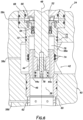
- FIG. 6 a more detailed cross-sectional view of the flow restrictor 42 is representatively illustrated in the closed configuration. In this view, a pressure balancing feature of the flow restrictor 42 is more clearly seen.
- the closure member 44 has one or more openings 44c formed longitudinally through the closure member.
- the closure member 44 is also slidingly and sealingly received in a sleeve 68a extending downwardly (as viewed in FIG. 6 ) from the adapter 68.
- One or more seals 74 are sealingly engaged between the sleeve 68a and an exterior surface of the closure member 44.
- the closure member 44 in sealing engagement with the seat 46 (e.g., with the FIG. 3 sealing surfaces 44a or b, and 46a or b, sealingly engaged with each other), fluid flow through the flow restrictor 42 and passage 38 is prevented.
- the openings 44c provide for fluid communication between the flow passage 38 downstream of the flow restrictor 42, and an annular chamber 76 formed radially between the stem 52 and the adapter sleeve 68a.
- the chamber 76 is also positioned longitudinally between the seal 64 and the seals 74.
- the scope of this disclosure is not limited to use of the openings 44c in the closure member 44 for providing fluid communication between the passage 38 and the chamber 76.
- fluid communication could be provided via one or more openings or other fluid flow paths in the stem 52, in a retainer 78 used to releasably secure the closure member 44 to the stem, or in another component of the flow choke 24.
- the actuator 50 (via the stem 52) can exert a longitudinal force on the closure member 44, for example, to maintain the closure member in its closed position or to displace the closure member to its open position or an intermediate position.
- the actuator 50 will apply to the stem 52 a downward force only greater than an upward force due to the pressure in the flow passage 38 applied across a cross-sectional area of the stem (and not across a cross-sectional area of the closure member 44, since the closure member is pressure balanced). This reduces a need for the actuator 50 to apply such large longitudinal forces.
- FIG. 7 another example of the flow choke 24 is representatively illustrated.
- additional ports 56e,f and sensors 54e,f are provided.
- the sensor 54e is in fluid communication with the flow passage 38 upstream of the flow restrictor 42 via the port 56e
- the sensor 54f is in fluid communication with the flow passage 38 downstream of the flow restrictor 42 via the port 56f.
- the sensors 54e,f measure a density of the fluid 20 flowing through the passage 38, respectively upstream and downstream of the flow restrictor 42.
- a suitable density sensor for use as the sensors 54e,f with the FIG. 7 flow choke 24 is marketed by Rheonics, Inc. of Sugar Land, Texas, USA.
- a "DV" family of sensors available from Rheonics can measure viscosity in addition to density.
- any suitable density sensor may be used for the sensors 54e,f in keeping with the principles of this disclosure.
- a combination of flow rate, density, and temperature measurements can provide much of the same capability as a typical Coriolis flow meter (e.g., measurement of mass flow rate), with the additional capability of the adjustable flow restrictor 42 downstream of the sensors 54a,e and upstream of the sensors 54b,f.
- the fluid 20 specific gravity SG can be more accurately determined to improve flow rate Q calculation (see equation 2 above) in real-time.
- measurement of density upstream and downstream of the flow restrictor 42 will provide more information, for example, to determine if there is a phase change to the fluid 20 as it flows through the flow choke 24.
- sensors 54e,f and ports 56e,f are depicted in FIG. 7 as being positioned in a same lateral plane as the sensors 54a,b and ports 56a,b. However, in other examples, the sensors 54e,f or ports 56e,f may not be positioned in the same lateral plane as the sensors 54a,b and ports 56a,b.
- the flow choke 24 is provided with the external ports 56a,b,e,f that can facilitate determining fluid flow rate through the flow choke, external ports 56c,d that can facilitate early detection of seal 64, 74 leakage, sealing of the actuator stem 52 against the fluid 20 and pressure in the flow passage 38, and pressure balancing of the closure member 44.
- the flow choke 24 can include a variable flow restrictor 42 configured to restrict flow through a flow passage 38 extending through the flow choke 24, a first external port 56a in communication with the flow passage 38 upstream of the flow restrictor 42, a second external port 56b in communication with the flow passage 38 downstream of the flow restrictor 42, and at least one sensor 54a,b in communication with the first and second external ports 56a,b.
- the “at least one” sensor may comprise first and second pressure sensors 54a,b.
- the first pressure sensor 54a may be in communication with the first external port 56a
- the second pressure sensor 54b may be in communication with the second external port 56b.
- the "at least one" sensor may comprise first and second density sensors 54e,f.
- the first density sensor 54e may be in communication with an external port 56a or e, and the second density sensor 54f in communication with the second external port 56b or f.
- the flow choke 24 may include an actuator 50 including a displaceable stem 52.
- a restriction to the flow through the flow passage 38 may be varied in response to displacement of the stem 52.
- the flow choke 24 may include a third external port 56c in communication with a stem chamber 66 surrounding the stem 52.
- the third external port 56c may be isolated by the stem seal 64 from the fluid pressure in the flow passage 38.
- the flow choke 24 may include a fourth external port 56d in communication with a sleeve chamber 70.
- the sleeve chamber 70 may be positioned external to a sleeve 68a in which a closure member 44 of the flow restrictor 42 is slidingly and sealingly received.
- the sleeve chamber 70 may be isolated from the flow passage 38 by a sleeve seal 72.
- a longitudinally displaceable closure member 44 of the flow restrictor 42 may be pressure balanced in a longitudinal direction.
- a method of controlling flow of a well fluid 20 is also provided to the art by the above disclosure.
- the method can include the steps of: flowing the well fluid 20 through a flow passage 38 formed through a body 40 of a flow choke 24, the flow choke 24 including a flow restrictor 42, the flow restrictor 42 being operable to variably restrict flow through the flow passage 38; measuring a pressure differential ⁇ P between first and second external ports 56a,b of the flow choke 24, the first and second external ports 56a,b being in communication through the body 40 with respective upstream and downstream sides of the flow restrictor 42; and operating the flow restrictor 42, thereby varying a restriction to the flow through the flow passage 38, in response to the measured pressure differential ⁇ P.
- the varying step can include varying the restriction to the flow through the flow passage 38 in response to a change in the measured pressure differential ⁇ P.
- the method may include the step of determining a flow rate Q of the well fluid 20 through the flow passage 38, based on the measured pressure differential ⁇ P.
- the method may include the steps of: connecting at least one pressure sensor 54a,b to the first and second external ports 56a,b; receiving an output of the at least one pressure sensor 54a,b by a control system 26; and the control system 26 operating an actuator 50 of the flow choke 24.
- the “at least one pressure sensor” may comprise first and second pressure sensors 54a,b.
- the connecting step may include connecting the first and second pressure sensors 54a,b to the respective first and second external ports 56a,b.
- the output received by the control system 26 can comprise outputs of the first and second pressure sensors 54a,b.
- the operating step may include longitudinally displacing a closure member 44 of the flow restrictor 42.
- the method may further include balancing pressure across the closure member 44 in a longitudinal direction when the closure member 44 is not engaged with a seat 46 of the flow restrictor 42.
- the operating step may include displacing an actuator stem 52 of the flow choke 24.
- the method may further include sealing about the actuator stem 52, thereby isolating the actuator 50 from the flow passage 38.
- the method may include measuring density of a fluid 20 in the flow passage 38.
- the density measuring step may include measuring the density upstream and downstream of the flow restrictor 42.
- the well system 10 can include a pump 18 that pumps a well fluid 20, a flow choke 24 comprising a variable flow restrictor 42 that restricts flow of the well fluid 20 through a flow passage 38 extending through the flow choke 24, the variable flow restrictor 42 being operable by an actuator 50 that includes a displaceable stem 52, and the flow choke 24 further comprising a stem seal 64 that isolates the actuator 50 from the well fluid 20 in the flow choke 24, and a control system 26 that operates the actuator 50.
- a pump 18 that pumps a well fluid 20
- a flow choke 24 comprising a variable flow restrictor 42 that restricts flow of the well fluid 20 through a flow passage 38 extending through the flow choke 24, the variable flow restrictor 42 being operable by an actuator 50 that includes a displaceable stem 52, and the flow choke 24 further comprising a stem seal 64 that isolates the actuator 50 from the well fluid 20 in the flow choke 24, and a control system 26 that operates the actuator 50.
- the stem seal 64 may isolate the actuator 50 from fluid pressure in the flow passage 38 upstream of the flow restrictor 42, in a closed configuration of the flow choke 24.
- a longitudinally displaceable closure member 44 of the flow restrictor 42 may be pressure balanced in a longitudinal direction.
Landscapes
- Engineering & Computer Science (AREA)
- Life Sciences & Earth Sciences (AREA)
- Geology (AREA)
- Mining & Mineral Resources (AREA)
- Physics & Mathematics (AREA)
- Environmental & Geological Engineering (AREA)
- Fluid Mechanics (AREA)
- General Life Sciences & Earth Sciences (AREA)
- Geochemistry & Mineralogy (AREA)
- Geophysics (AREA)
- Mechanical Engineering (AREA)
- Flow Control (AREA)
Claims (14)
- Duse d'écoulement (24) pour une utilisation avec un puits souterrain, la duse d'écoulement (24) comprenant :un limiteur d'écoulement variable (42) configuré pour limiter un écoulement à travers un passage d'écoulement (38) s'étendant à travers la duse d'écoulement (24), dans laquelle, dans des configurations ouverte et intermédiaire de la duse d'écoulement (24), un élément de fermeture déplaçable longitudinalement (44) du limiteur d'écoulement (42) est entièrement équilibré en pression dans une direction longitudinale, de sorte qu'il n'y a pas de force nette exercée sur l'élément de fermeture (44) dans la direction longitudinale, en raison d'une pression de puits agissant sur des extrémités opposées du limiteur d'écoulement (42),un premier orifice externe (56a) en communication avec le passage d'écoulement (38) en amont du limiteur d'écoulement (42),un deuxième orifice externe (56b) en communication avec le passage d'écoulement (38) en aval du limiteur d'écoulement (42), etau moins un capteur (54) en communication avec le premier et le deuxième orifice externe (56a,b).
- Duse d'écoulement (24) selon la revendication 1, dans laquelle l'au moins un capteur (54) comprend des premier et deuxième capteurs de pression (54a,b), le premier capteur de pression (54a) étant en communication avec le premier orifice externe (56a), et le deuxième capteur de pression (54b) étant en communication avec le deuxième orifice externe (56b).
- Duse d'écoulement (24) selon la revendication 1, dans laquelle l'au moins un capteur (54) comprend des premier et deuxième capteurs de densité (54e,f), le premier capteur de densité (54e) étant en communication avec le premier orifice externe (56a), et le deuxième capteur de densité (54f) étant en communication avec le deuxième orifice externe (56b).
- Duse d'écoulement (24) selon la revendication 1, comprenant en outre :un actionneur (50) incluant une tige déplaçable (52), une limitation de l'écoulement à travers le passage d'écoulement (38) pouvant être modifiée en réponse à un déplacement de la tige (52), etun joint de tige (64) qui se met en prise étanche avec la tige (52) et isole l'actionneur (50) vis-à-vis d'une pression de fluide dans le passage d'écoulement (38).
- Duse d'écoulement (24) selon la revendication 4, dans laquelle le joint de tige (64) isole l'actionneur (50) de la pression de fluide dans le passage d'écoulement (38) en aval du limiteur d'écoulement (42), dans une configuration fermée de la duse d'écoulement (24).
- Duse d'écoulement (24) selon la revendication 4, comprenant en outre un troisième orifice externe (56c) en communication avec une chambre de tige (66) entourant la tige (52), le troisième orifice externe (56c) étant isolé par le joint de tige (64) vis-à-vis de la pression de fluide dans le passage d'écoulement (38).
- Procédé de régulation d'écoulement d'un fluide de puits (20), le procédé comprenant :l'écoulement du fluide de puits (20) à travers un passage d'écoulement (38) formé à travers un corps (40) d'une duse d'écoulement (24), la duse d'écoulement (24) incluant un limiteur d'écoulement (42), le limiteur d'écoulement (42) pouvant être actionné pour limiter de façon variable un écoulement à travers le passage d'écoulement (38), et dans des configurations ouverte et intermédiaire de la duse d'écoulement (24), un élément de fermeture déplaçable longitudinalement (44) du limiteur d'écoulement (42) est entièrement équilibré en pression dans une direction longitudinale, de sorte qu'il n'y a pas de force nette exercée sur l'élément de fermeture (44) dans la direction longitudinale, en raison d'une pression de puits agissant sur des extrémités opposées du limiteur d'écoulement (42),la mesure d'une différence de pression (ΔP) entre des premier et deuxième orifices externes (56a, b) de la duse d'écoulement (24), les premier et deuxième orifices externes (56a, b) étant en communication à travers le corps (40) avec des côtés amont et aval respectifs du limiteur d'écoulement (42), etl'actionnement du limiteur d'écoulement (42), ainsi faisant varier une limitation de l'écoulement à travers le passage d'écoulement (38), en réponse à la différence de pression (ΔP) mesurée.
- Procédé selon la revendication 7, dans lequel la variation comprend en outre la variation de la limitation de l'écoulement à travers le passage d'écoulement (38) en réponse à un changement de la différence de pression (ΔP) mesurée.
- Procédé selon la revendication 7, comprenant en outre la détermination d'un débit (Q) du fluide de puits (20) à travers le passage d'écoulement (38) sur la base de la différence de pression(ΔP) mesurée.
- Procédé selon la revendication 7, comprenant en outre :la connexion d'au moins un capteur de pression (54) aux premier et deuxième orifices externes (56a,b),la réception d'une sortie de l'au moins un capteur de pression (54) par un système de commande (26), etl'actionnement, par le système de commande (26), d'un actionneur (50) de la duse d'écoulement (24).
- Procédé selon la revendication 10, dans lequel l'au moins un capteur de pression (54) comprend des premier et deuxième capteurs de pression (54a,b), la connexion comprend la connexion des premier et deuxième capteurs de pression (54a,b) aux premier et deuxième orifices externes (56a, b) respectifs, et la sortie comprend des sorties des premier et deuxième capteurs de pression (54a, b).
- Procédé selon la revendication 7, dans lequel l'actionnement comprend le déplacement longitudinal de l'élément de fermeture (44) du limiteur d'écoulement (42), et comprenant en outre l'équilibrage de pression à travers l'élément de fermeture (44) dans la direction longitudinale lorsque l'élément de fermeture (44) est désengagé d'un siège (46) du limiteur d'écoulement (42).
- Procédé selon la revendication 7, dans lequel l'actionnement comprend le déplacement d'une tige d'actionneur (52) de la duse d'écoulement (24), et comprenant en outre la fourniture d'un joint autour de la tige d'actionneur (52), ainsi isolant l'actionneur (50) vis-à-vis du passage d'écoulement (38).
- Procédé selon la revendication 7, comprenant en outre la mesure de densité du fluide (20) dans le passage d'écoulement (38).
Applications Claiming Priority (3)
| Application Number | Priority Date | Filing Date | Title |
|---|---|---|---|
| US15/727,293 US10801303B2 (en) | 2017-10-06 | 2017-10-06 | Well fluid flow control choke |
| EP18786620.7A EP3692242A1 (fr) | 2017-10-06 | 2018-09-27 | Duse de régulation de débit de fluide de puits |
| PCT/US2018/053158 WO2019070505A1 (fr) | 2017-10-06 | 2018-09-27 | Duse de régulation de débit de fluide de puits |
Related Parent Applications (1)
| Application Number | Title | Priority Date | Filing Date |
|---|---|---|---|
| EP18786620.7A Division EP3692242A1 (fr) | 2017-10-06 | 2018-09-27 | Duse de régulation de débit de fluide de puits |
Publications (2)
| Publication Number | Publication Date |
|---|---|
| EP4177438A1 EP4177438A1 (fr) | 2023-05-10 |
| EP4177438B1 true EP4177438B1 (fr) | 2025-07-09 |
Family
ID=63858196
Family Applications (2)
| Application Number | Title | Priority Date | Filing Date |
|---|---|---|---|
| EP22216234.9A Active EP4177438B1 (fr) | 2017-10-06 | 2018-09-27 | Volet de régulation d'écoulement de fluide de puits |
| EP18786620.7A Withdrawn EP3692242A1 (fr) | 2017-10-06 | 2018-09-27 | Duse de régulation de débit de fluide de puits |
Family Applications After (1)
| Application Number | Title | Priority Date | Filing Date |
|---|---|---|---|
| EP18786620.7A Withdrawn EP3692242A1 (fr) | 2017-10-06 | 2018-09-27 | Duse de régulation de débit de fluide de puits |
Country Status (5)
| Country | Link |
|---|---|
| US (2) | US10801303B2 (fr) |
| EP (2) | EP4177438B1 (fr) |
| BR (1) | BR112020006645A2 (fr) |
| SG (1) | SG11202002867YA (fr) |
| WO (1) | WO2019070505A1 (fr) |
Families Citing this family (7)
| Publication number | Priority date | Publication date | Assignee | Title |
|---|---|---|---|---|
| US10801303B2 (en) | 2017-10-06 | 2020-10-13 | Weatherford Technology Holdings, Llc | Well fluid flow control choke |
| CN113027426B (zh) * | 2019-12-09 | 2023-11-28 | 中国石油天然气股份有限公司 | 漏失压力确定方法、装置及存储介质 |
| WO2022006045A1 (fr) * | 2020-06-30 | 2022-01-06 | Sri Energy, Inc. | Système d'étranglement avec aptitude au passage de gros débris |
| US11702896B2 (en) * | 2021-03-05 | 2023-07-18 | Weatherford Technology Holdings, Llc | Flow measurement apparatus and associated systems and methods |
| US11661805B2 (en) | 2021-08-02 | 2023-05-30 | Weatherford Technology Holdings, Llc | Real time flow rate and rheology measurement |
| US12222268B1 (en) | 2023-07-20 | 2025-02-11 | Weatherford Technology Holdings, Llc | Non-intrusive rheometer for use in well operations |
| US12546184B2 (en) * | 2024-05-30 | 2026-02-10 | Schlumberger Technology Corporation | Choke system to control fluid pressure |
Family Cites Families (26)
| Publication number | Priority date | Publication date | Assignee | Title |
|---|---|---|---|---|
| US4240609A (en) * | 1978-08-07 | 1980-12-23 | Cameron Iron Works, Inc. | Flow control apparatus |
| US4971099A (en) * | 1989-12-15 | 1990-11-20 | Cooper Industries, Inc. | Pressure balanced cartridge choke valve |
| US5074519A (en) * | 1990-11-09 | 1991-12-24 | Cooper Industries, Inc. | Fail-close hydraulically actuated control choke |
| US6283152B1 (en) * | 1999-03-01 | 2001-09-04 | Cor-Val, Inc. | Multiple sleeve valve assembly |
| US6446664B1 (en) | 1999-09-22 | 2002-09-10 | Power Chokes, Inc. | Erosion resistant wear sleeve for high pressure valves |
| US6609533B2 (en) * | 2001-03-08 | 2003-08-26 | World Wide Oilfield Machine, Inc. | Valve actuator and method |
| CA2369574C (fr) | 2002-01-25 | 2005-04-12 | Harry Richard Cove | Volet de depart avec transmetteurs de pression |
| US6782949B2 (en) * | 2002-01-29 | 2004-08-31 | Master Flo Valve Inc. | Choke valve with pressure transmitters |
| US6920942B2 (en) | 2003-01-29 | 2005-07-26 | Varco I/P, Inc. | Method and apparatus for directly controlling pressure and position associated with an adjustable choke apparatus |
| US6883614B2 (en) | 2003-05-02 | 2005-04-26 | Power Chokes | Modular actuator system for valves and chokes |
| US20050092523A1 (en) * | 2003-10-30 | 2005-05-05 | Power Chokes, L.P. | Well pressure control system |
| US20080149182A1 (en) | 2006-12-21 | 2008-06-26 | M-I Llc | Linear motor to control hydraulic force |
| US8286935B2 (en) | 2008-05-28 | 2012-10-16 | Vetco Gray Inc. | Subsea electric actuator using linear motor |
| IT1391371B1 (it) | 2008-10-07 | 2011-12-13 | Eni Spa | Sistema valvola di testa pozzo per la regolazione del flusso con funzionalita' integrata di misurazione della portata multifase |
| EP2396498B1 (fr) * | 2009-02-11 | 2015-08-05 | M-I L.L.C. | Système de duse automatique |
| US8819940B2 (en) | 2010-02-26 | 2014-09-02 | Tolomatic, Inc. | Method for manufacturing a linear actuator |
| US8978497B2 (en) | 2011-05-26 | 2015-03-17 | Tolomatic, Inc. | Linear actuator with anti-rotation mechanism |
| US9222555B2 (en) | 2012-08-06 | 2015-12-29 | Cameron International Corporation | Linear actuator |
| US9708886B2 (en) | 2013-03-15 | 2017-07-18 | Cameron International Corporation | Control choke system |
| US9334936B2 (en) | 2013-04-18 | 2016-05-10 | Tolomatic, Inc. | High stiffness thrust component for linear actuator |
| US10145205B2 (en) * | 2014-10-20 | 2018-12-04 | Cameron International Corporation | System for controlling fluid flow |
| US10536052B2 (en) | 2015-06-16 | 2020-01-14 | Tolomatic, Inc. | Actuator for choke valve |
| GB2541926B (en) | 2015-09-04 | 2021-07-14 | Equinor Energy As | System and method for monitoring the state of a choke valve in a managed pressure drilling system |
| US10227838B2 (en) | 2016-05-10 | 2019-03-12 | Weatherford Technology Holdings, Llc | Drilling system and method having flow measurement choke |
| US10801303B2 (en) | 2017-10-06 | 2020-10-13 | Weatherford Technology Holdings, Llc | Well fluid flow control choke |
| US10502054B2 (en) * | 2017-10-24 | 2019-12-10 | Onesubsea Ip Uk Limited | Fluid properties measurement using choke valve system |
-
2017
- 2017-10-06 US US15/727,293 patent/US10801303B2/en active Active
-
2018
- 2018-09-27 BR BR112020006645-1A patent/BR112020006645A2/pt not_active Application Discontinuation
- 2018-09-27 EP EP22216234.9A patent/EP4177438B1/fr active Active
- 2018-09-27 EP EP18786620.7A patent/EP3692242A1/fr not_active Withdrawn
- 2018-09-27 WO PCT/US2018/053158 patent/WO2019070505A1/fr not_active Ceased
- 2018-09-27 SG SG11202002867YA patent/SG11202002867YA/en unknown
-
2020
- 2020-08-27 US US17/004,582 patent/US11608710B2/en active Active
Also Published As
| Publication number | Publication date |
|---|---|
| SG11202002867YA (en) | 2020-04-29 |
| US20190106963A1 (en) | 2019-04-11 |
| EP3692242A1 (fr) | 2020-08-12 |
| WO2019070505A1 (fr) | 2019-04-11 |
| BR112020006645A2 (pt) | 2020-09-24 |
| EP4177438A1 (fr) | 2023-05-10 |
| US20200399983A1 (en) | 2020-12-24 |
| US10801303B2 (en) | 2020-10-13 |
| US11608710B2 (en) | 2023-03-21 |
Similar Documents
| Publication | Publication Date | Title |
|---|---|---|
| EP4177438B1 (fr) | Volet de régulation d'écoulement de fluide de puits | |
| US10227838B2 (en) | Drilling system and method having flow measurement choke | |
| DK2536917T3 (en) | valve Plant | |
| EP2785971B1 (fr) | Utilisation de mesures de pression de fond de puits pendant le forage permettant de détecter et de mitiger les afflux | |
| US7836956B2 (en) | Positional control of downhole actuators | |
| EP2085753B1 (fr) | Débitmètre inséré dans un clapet à bille | |
| CN103132956B (zh) | 海床井流入量控制系统 | |
| US20160281466A1 (en) | Gravel pack-circulating sleeve with hydraulic lock | |
| US11702896B2 (en) | Flow measurement apparatus and associated systems and methods | |
| CN104246122A (zh) | 流动控制装置和方法 | |
| EP3542026B1 (fr) | Soupape d'injection de produit chimique à flux de dérivation de tige | |
| AU2020371271B2 (en) | Well control system and method of use | |
| US20110203805A1 (en) | Valving Device and Method of Valving | |
| US9151137B2 (en) | Configurations and methods for improved subsea production control | |
| US10837275B2 (en) | Leak detection for downhole isolation valve | |
| EP3559395B1 (fr) | Réduction étagée de l'espace annulaire pour forage sous pression contrôlée | |
| US9494013B2 (en) | Configurable and expandable fluid metering system | |
| US20150083428A1 (en) | Auto-filling of a tubular string in a subterranean well | |
| BR112019012923B1 (pt) | Sistema de perfuração de poço |
Legal Events
| Date | Code | Title | Description |
|---|---|---|---|
| PUAI | Public reference made under article 153(3) epc to a published international application that has entered the european phase |
Free format text: ORIGINAL CODE: 0009012 |
|
| STAA | Information on the status of an ep patent application or granted ep patent |
Free format text: STATUS: THE APPLICATION HAS BEEN PUBLISHED |
|
| AC | Divisional application: reference to earlier application |
Ref document number: 3692242 Country of ref document: EP Kind code of ref document: P |
|
| AK | Designated contracting states |
Kind code of ref document: A1 Designated state(s): AL AT BE BG CH CY CZ DE DK EE ES FI FR GB GR HR HU IE IS IT LI LT LU LV MC MK MT NL NO PL PT RO RS SE SI SK SM TR |
|
| STAA | Information on the status of an ep patent application or granted ep patent |
Free format text: STATUS: REQUEST FOR EXAMINATION WAS MADE |
|
| 17P | Request for examination filed |
Effective date: 20231101 |
|
| RBV | Designated contracting states (corrected) |
Designated state(s): AL AT BE BG CH CY CZ DE DK EE ES FI FR GB GR HR HU IE IS IT LI LT LU LV MC MK MT NL NO PL PT RO RS SE SI SK SM TR |
|
| STAA | Information on the status of an ep patent application or granted ep patent |
Free format text: STATUS: EXAMINATION IS IN PROGRESS |
|
| 17Q | First examination report despatched |
Effective date: 20240314 |
|
| GRAP | Despatch of communication of intention to grant a patent |
Free format text: ORIGINAL CODE: EPIDOSNIGR1 |
|
| STAA | Information on the status of an ep patent application or granted ep patent |
Free format text: STATUS: GRANT OF PATENT IS INTENDED |
|
| RIC1 | Information provided on ipc code assigned before grant |
Ipc: E21B 34/02 20060101ALI20250116BHEP Ipc: E21B 47/117 20120101ALI20250116BHEP Ipc: E21B 21/08 20060101ALI20250116BHEP Ipc: E21B 47/10 20120101ALI20250116BHEP Ipc: E21B 47/06 20120101ALI20250116BHEP Ipc: E21B 21/10 20060101AFI20250116BHEP |
|
| INTG | Intention to grant announced |
Effective date: 20250130 |
|
| GRAS | Grant fee paid |
Free format text: ORIGINAL CODE: EPIDOSNIGR3 |
|
| GRAA | (expected) grant |
Free format text: ORIGINAL CODE: 0009210 |
|
| STAA | Information on the status of an ep patent application or granted ep patent |
Free format text: STATUS: THE PATENT HAS BEEN GRANTED |
|
| AC | Divisional application: reference to earlier application |
Ref document number: 3692242 Country of ref document: EP Kind code of ref document: P |
|
| AK | Designated contracting states |
Kind code of ref document: B1 Designated state(s): AL AT BE BG CH CY CZ DE DK EE ES FI FR GB GR HR HU IE IS IT LI LT LU LV MC MK MT NL NO PL PT RO RS SE SI SK SM TR |
|
| REG | Reference to a national code |
Ref country code: GB Ref legal event code: FG4D |
|
| REG | Reference to a national code |
Ref country code: CH Ref legal event code: EP |
|
| REG | Reference to a national code |
Ref country code: IE Ref legal event code: FG4D |
|
| REG | Reference to a national code |
Ref country code: DE Ref legal event code: R096 Ref document number: 602018083546 Country of ref document: DE |
|
| REG | Reference to a national code |
Ref country code: NL Ref legal event code: MP Effective date: 20250709 |
|
| PG25 | Lapsed in a contracting state [announced via postgrant information from national office to epo] |
Ref country code: PT Free format text: LAPSE BECAUSE OF FAILURE TO SUBMIT A TRANSLATION OF THE DESCRIPTION OR TO PAY THE FEE WITHIN THE PRESCRIBED TIME-LIMIT Effective date: 20251110 |
|
| PG25 | Lapsed in a contracting state [announced via postgrant information from national office to epo] |
Ref country code: NL Free format text: LAPSE BECAUSE OF FAILURE TO SUBMIT A TRANSLATION OF THE DESCRIPTION OR TO PAY THE FEE WITHIN THE PRESCRIBED TIME-LIMIT Effective date: 20250709 |
|
| REG | Reference to a national code |
Ref country code: AT Ref legal event code: MK05 Ref document number: 1811987 Country of ref document: AT Kind code of ref document: T Effective date: 20250709 |
|
| PG25 | Lapsed in a contracting state [announced via postgrant information from national office to epo] |
Ref country code: IS Free format text: LAPSE BECAUSE OF FAILURE TO SUBMIT A TRANSLATION OF THE DESCRIPTION OR TO PAY THE FEE WITHIN THE PRESCRIBED TIME-LIMIT Effective date: 20251109 |
|
| PGFP | Annual fee paid to national office [announced via postgrant information from national office to epo] |
Ref country code: DE Payment date: 20251028 Year of fee payment: 8 |
|
| PGFP | Annual fee paid to national office [announced via postgrant information from national office to epo] |
Ref country code: GB Payment date: 20251030 Year of fee payment: 8 |
|
| PGFP | Annual fee paid to national office [announced via postgrant information from national office to epo] |
Ref country code: NO Payment date: 20251113 Year of fee payment: 8 |
|
| REG | Reference to a national code |
Ref country code: LT Ref legal event code: MG9D |
|
| PG25 | Lapsed in a contracting state [announced via postgrant information from national office to epo] |
Ref country code: AT Free format text: LAPSE BECAUSE OF FAILURE TO SUBMIT A TRANSLATION OF THE DESCRIPTION OR TO PAY THE FEE WITHIN THE PRESCRIBED TIME-LIMIT Effective date: 20250709 |
|
| PG25 | Lapsed in a contracting state [announced via postgrant information from national office to epo] |
Ref country code: FI Free format text: LAPSE BECAUSE OF FAILURE TO SUBMIT A TRANSLATION OF THE DESCRIPTION OR TO PAY THE FEE WITHIN THE PRESCRIBED TIME-LIMIT Effective date: 20250709 |
|
| PG25 | Lapsed in a contracting state [announced via postgrant information from national office to epo] |
Ref country code: HR Free format text: LAPSE BECAUSE OF FAILURE TO SUBMIT A TRANSLATION OF THE DESCRIPTION OR TO PAY THE FEE WITHIN THE PRESCRIBED TIME-LIMIT Effective date: 20250709 |
|
| PG25 | Lapsed in a contracting state [announced via postgrant information from national office to epo] |
Ref country code: GR Free format text: LAPSE BECAUSE OF FAILURE TO SUBMIT A TRANSLATION OF THE DESCRIPTION OR TO PAY THE FEE WITHIN THE PRESCRIBED TIME-LIMIT Effective date: 20251010 |
|
| PG25 | Lapsed in a contracting state [announced via postgrant information from national office to epo] |
Ref country code: SE Free format text: LAPSE BECAUSE OF FAILURE TO SUBMIT A TRANSLATION OF THE DESCRIPTION OR TO PAY THE FEE WITHIN THE PRESCRIBED TIME-LIMIT Effective date: 20250709 |
|
| PG25 | Lapsed in a contracting state [announced via postgrant information from national office to epo] |
Ref country code: LV Free format text: LAPSE BECAUSE OF FAILURE TO SUBMIT A TRANSLATION OF THE DESCRIPTION OR TO PAY THE FEE WITHIN THE PRESCRIBED TIME-LIMIT Effective date: 20250709 |
|
| PG25 | Lapsed in a contracting state [announced via postgrant information from national office to epo] |
Ref country code: PL Free format text: LAPSE BECAUSE OF FAILURE TO SUBMIT A TRANSLATION OF THE DESCRIPTION OR TO PAY THE FEE WITHIN THE PRESCRIBED TIME-LIMIT Effective date: 20250709 Ref country code: BG Free format text: LAPSE BECAUSE OF FAILURE TO SUBMIT A TRANSLATION OF THE DESCRIPTION OR TO PAY THE FEE WITHIN THE PRESCRIBED TIME-LIMIT Effective date: 20250709 |
|
| PG25 | Lapsed in a contracting state [announced via postgrant information from national office to epo] |
Ref country code: RS Free format text: LAPSE BECAUSE OF FAILURE TO SUBMIT A TRANSLATION OF THE DESCRIPTION OR TO PAY THE FEE WITHIN THE PRESCRIBED TIME-LIMIT Effective date: 20251009 |
|
| PG25 | Lapsed in a contracting state [announced via postgrant information from national office to epo] |
Ref country code: ES Free format text: LAPSE BECAUSE OF FAILURE TO SUBMIT A TRANSLATION OF THE DESCRIPTION OR TO PAY THE FEE WITHIN THE PRESCRIBED TIME-LIMIT Effective date: 20250709 |
|
| PG25 | Lapsed in a contracting state [announced via postgrant information from national office to epo] |
Ref country code: RO Free format text: LAPSE BECAUSE OF FAILURE TO SUBMIT A TRANSLATION OF THE DESCRIPTION OR TO PAY THE FEE WITHIN THE PRESCRIBED TIME-LIMIT Effective date: 20250709 |
|
| PG25 | Lapsed in a contracting state [announced via postgrant information from national office to epo] |
Ref country code: SM Free format text: LAPSE BECAUSE OF FAILURE TO SUBMIT A TRANSLATION OF THE DESCRIPTION OR TO PAY THE FEE WITHIN THE PRESCRIBED TIME-LIMIT Effective date: 20250709 |
|
| PG25 | Lapsed in a contracting state [announced via postgrant information from national office to epo] |
Ref country code: DK Free format text: LAPSE BECAUSE OF FAILURE TO SUBMIT A TRANSLATION OF THE DESCRIPTION OR TO PAY THE FEE WITHIN THE PRESCRIBED TIME-LIMIT Effective date: 20250709 |
|
| PG25 | Lapsed in a contracting state [announced via postgrant information from national office to epo] |
Ref country code: IT Free format text: LAPSE BECAUSE OF FAILURE TO SUBMIT A TRANSLATION OF THE DESCRIPTION OR TO PAY THE FEE WITHIN THE PRESCRIBED TIME-LIMIT Effective date: 20250709 |
|
| PG25 | Lapsed in a contracting state [announced via postgrant information from national office to epo] |
Ref country code: CZ Free format text: LAPSE BECAUSE OF FAILURE TO SUBMIT A TRANSLATION OF THE DESCRIPTION OR TO PAY THE FEE WITHIN THE PRESCRIBED TIME-LIMIT Effective date: 20250709 |
|
| PG25 | Lapsed in a contracting state [announced via postgrant information from national office to epo] |
Ref country code: EE Free format text: LAPSE BECAUSE OF FAILURE TO SUBMIT A TRANSLATION OF THE DESCRIPTION OR TO PAY THE FEE WITHIN THE PRESCRIBED TIME-LIMIT Effective date: 20250709 Ref country code: SK Free format text: LAPSE BECAUSE OF FAILURE TO SUBMIT A TRANSLATION OF THE DESCRIPTION OR TO PAY THE FEE WITHIN THE PRESCRIBED TIME-LIMIT Effective date: 20250709 |