EP4177460A1 - Procédé de refroidissement efficace d'une éolienne - Google Patents
Procédé de refroidissement efficace d'une éolienne Download PDFInfo
- Publication number
- EP4177460A1 EP4177460A1 EP21206380.4A EP21206380A EP4177460A1 EP 4177460 A1 EP4177460 A1 EP 4177460A1 EP 21206380 A EP21206380 A EP 21206380A EP 4177460 A1 EP4177460 A1 EP 4177460A1
- Authority
- EP
- European Patent Office
- Prior art keywords
- cooling
- power
- wind
- temperature
- component
- Prior art date
- Legal status (The legal status is an assumption and is not a legal conclusion. Google has not performed a legal analysis and makes no representation as to the accuracy of the status listed.)
- Pending
Links
- 238000001816 cooling Methods 0.000 title claims abstract description 234
- 238000000034 method Methods 0.000 title claims abstract description 19
- 238000011156 evaluation Methods 0.000 claims abstract description 70
- 230000008859 change Effects 0.000 claims abstract description 24
- 238000009434 installation Methods 0.000 claims description 35
- 230000009467 reduction Effects 0.000 claims description 24
- 238000004519 manufacturing process Methods 0.000 claims description 7
- 230000006870 function Effects 0.000 description 17
- 230000000694 effects Effects 0.000 description 5
- 230000004913 activation Effects 0.000 description 3
- 239000002826 coolant Substances 0.000 description 3
- 230000000454 anti-cipatory effect Effects 0.000 description 2
- 230000033228 biological regulation Effects 0.000 description 2
- 238000004590 computer program Methods 0.000 description 2
- 239000000110 cooling liquid Substances 0.000 description 2
- 230000003247 decreasing effect Effects 0.000 description 2
- 230000001419 dependent effect Effects 0.000 description 2
- 238000011161 development Methods 0.000 description 2
- 230000018109 developmental process Effects 0.000 description 2
- 239000007788 liquid Substances 0.000 description 2
- 238000013021 overheating Methods 0.000 description 2
- 238000010248 power generation Methods 0.000 description 2
- 230000032683 aging Effects 0.000 description 1
- 238000004458 analytical method Methods 0.000 description 1
- 238000013473 artificial intelligence Methods 0.000 description 1
- 230000008901 benefit Effects 0.000 description 1
- 230000005540 biological transmission Effects 0.000 description 1
- 238000004364 calculation method Methods 0.000 description 1
- 238000013461 design Methods 0.000 description 1
- 230000006866 deterioration Effects 0.000 description 1
- 238000010586 diagram Methods 0.000 description 1
- 230000005611 electricity Effects 0.000 description 1
- 230000005520 electrodynamics Effects 0.000 description 1
- 230000006872 improvement Effects 0.000 description 1
- 238000010801 machine learning Methods 0.000 description 1
- 238000012544 monitoring process Methods 0.000 description 1
- 238000004393 prognosis Methods 0.000 description 1
- 238000005086 pumping Methods 0.000 description 1
- 230000004044 response Effects 0.000 description 1
- 230000035882 stress Effects 0.000 description 1
- 230000001360 synchronised effect Effects 0.000 description 1
Images

Classifications
-
- F—MECHANICAL ENGINEERING; LIGHTING; HEATING; WEAPONS; BLASTING
- F03—MACHINES OR ENGINES FOR LIQUIDS; WIND, SPRING, OR WEIGHT MOTORS; PRODUCING MECHANICAL POWER OR A REACTIVE PROPULSIVE THRUST, NOT OTHERWISE PROVIDED FOR
- F03D—WIND MOTORS
- F03D80/00—Details, components or accessories not provided for in groups F03D1/00 - F03D17/00
- F03D80/60—Cooling or heating of wind motors
-
- F—MECHANICAL ENGINEERING; LIGHTING; HEATING; WEAPONS; BLASTING
- F03—MACHINES OR ENGINES FOR LIQUIDS; WIND, SPRING, OR WEIGHT MOTORS; PRODUCING MECHANICAL POWER OR A REACTIVE PROPULSIVE THRUST, NOT OTHERWISE PROVIDED FOR
- F03D—WIND MOTORS
- F03D17/00—Monitoring or testing of wind motors, e.g. diagnostics
-
- F—MECHANICAL ENGINEERING; LIGHTING; HEATING; WEAPONS; BLASTING
- F03—MACHINES OR ENGINES FOR LIQUIDS; WIND, SPRING, OR WEIGHT MOTORS; PRODUCING MECHANICAL POWER OR A REACTIVE PROPULSIVE THRUST, NOT OTHERWISE PROVIDED FOR
- F03D—WIND MOTORS
- F03D7/00—Controlling wind motors
- F03D7/02—Controlling wind motors the wind motors having rotation axis substantially parallel to the air flow entering the rotor
-
- F—MECHANICAL ENGINEERING; LIGHTING; HEATING; WEAPONS; BLASTING
- F03—MACHINES OR ENGINES FOR LIQUIDS; WIND, SPRING, OR WEIGHT MOTORS; PRODUCING MECHANICAL POWER OR A REACTIVE PROPULSIVE THRUST, NOT OTHERWISE PROVIDED FOR
- F03D—WIND MOTORS
- F03D9/00—Adaptations of wind motors for special use; Combinations of wind motors with apparatus driven thereby; Wind motors specially adapted for installation in particular locations
- F03D9/20—Wind motors characterised by the driven apparatus
- F03D9/25—Wind motors characterised by the driven apparatus the apparatus being an electrical generator
- F03D9/255—Wind motors characterised by the driven apparatus the apparatus being an electrical generator connected to electrical distribution networks; Arrangements therefor
-
- F—MECHANICAL ENGINEERING; LIGHTING; HEATING; WEAPONS; BLASTING
- F05—INDEXING SCHEMES RELATING TO ENGINES OR PUMPS IN VARIOUS SUBCLASSES OF CLASSES F01-F04
- F05B—INDEXING SCHEME RELATING TO WIND, SPRING, WEIGHT, INERTIA OR LIKE MOTORS, TO MACHINES OR ENGINES FOR LIQUIDS COVERED BY SUBCLASSES F03B, F03D AND F03G
- F05B2260/00—Function
- F05B2260/20—Heat transfer, e.g. cooling
-
- F—MECHANICAL ENGINEERING; LIGHTING; HEATING; WEAPONS; BLASTING
- F05—INDEXING SCHEMES RELATING TO ENGINES OR PUMPS IN VARIOUS SUBCLASSES OF CLASSES F01-F04
- F05B—INDEXING SCHEME RELATING TO WIND, SPRING, WEIGHT, INERTIA OR LIKE MOTORS, TO MACHINES OR ENGINES FOR LIQUIDS COVERED BY SUBCLASSES F03B, F03D AND F03G
- F05B2270/00—Control
- F05B2270/10—Purpose of the control system
- F05B2270/20—Purpose of the control system to optimise the performance of a machine
-
- F—MECHANICAL ENGINEERING; LIGHTING; HEATING; WEAPONS; BLASTING
- F05—INDEXING SCHEMES RELATING TO ENGINES OR PUMPS IN VARIOUS SUBCLASSES OF CLASSES F01-F04
- F05B—INDEXING SCHEME RELATING TO WIND, SPRING, WEIGHT, INERTIA OR LIKE MOTORS, TO MACHINES OR ENGINES FOR LIQUIDS COVERED BY SUBCLASSES F03B, F03D AND F03G
- F05B2270/00—Control
- F05B2270/30—Control parameters, e.g. input parameters
- F05B2270/303—Temperature
- F05B2270/3032—Temperature excessive temperatures, e.g. caused by overheating
-
- Y—GENERAL TAGGING OF NEW TECHNOLOGICAL DEVELOPMENTS; GENERAL TAGGING OF CROSS-SECTIONAL TECHNOLOGIES SPANNING OVER SEVERAL SECTIONS OF THE IPC; TECHNICAL SUBJECTS COVERED BY FORMER USPC CROSS-REFERENCE ART COLLECTIONS [XRACs] AND DIGESTS
- Y02—TECHNOLOGIES OR APPLICATIONS FOR MITIGATION OR ADAPTATION AGAINST CLIMATE CHANGE
- Y02E—REDUCTION OF GREENHOUSE GAS [GHG] EMISSIONS, RELATED TO ENERGY GENERATION, TRANSMISSION OR DISTRIBUTION
- Y02E10/00—Energy generation through renewable energy sources
- Y02E10/70—Wind energy
- Y02E10/72—Wind turbines with rotation axis in wind direction
Definitions
- the present invention relates to a method for operating a wind power plant and it relates to a corresponding wind power plant.
- Wind turbines generate power from the wind and feed it into an electrical supply network. Cooling can be provided to increase the efficiency of the generator used for this purpose. the cooling then ensures that the generator does not get too hot and thus does not leave an optimum working point or does not leave it too much. However, cooling can also prevent a generator from overheating and being damaged as a result.
- Active cooling systems are particularly efficient, but they themselves require power and can therefore slightly impair the increase in efficiency achieved.
- the present invention is therefore based on the object of addressing at least one of the problems mentioned above.
- a solution is to be proposed in which the negative influences of the cooling on the generation or output of power are reduced as far as possible.
- an alternative solution to previously known solutions should be proposed.
- a method according to claim 1 is proposed.
- the method thus relates to the operation of a wind energy plant that has a rotor. It generates power from wind, which has a wind speed, and feeds this power into an electrical supply network.
- the wind energy installation controls a cooling of a component of the wind energy installation.
- this cooling can also be referred to as active cooling.
- Controlling the cooling can in particular include controlling and thus operating at least one pump for pumping coolant and also or alternatively controlling and thus operating at least one fan or a fan unit.
- Such a fan unit can directly generate and move an air flow provided for cooling, and/or drive air through a recooler for cooling.
- the control of the cooling includes the control of at least one pump and also the control of at least one blower unit.
- the pump can pump cooling liquid through the component for cooling and the cooling liquid can be cooled again in a dry cooler.
- At least one blower unit can be provided to improve the cooling of the coolant in the recooler.
- a blower unit can also be synonymously referred to simply as a blower, fan, fan unit or ventilator.
- an operational evaluation in which an operational state or a change in the operational state is evaluated.
- Various examples of a company evaluation are explained below.
- a simple example can be that, as an operational evaluation, it is evaluated whether the wind turbine is feeding in nominal power.
- the cooling is controlled as a function of a component temperature and additionally as a function of the operational evaluation.
- the Control of the cooling is thus carried out depending on at least two criteria.
- cooling is controlled at all, or whether it remains inactive or passive, depends on the component temperature and also on the operational evaluation.
- the cooling can also be controlled with different strengths depending on the component temperature and the operational evaluation. Controlling a speed of a pump and/or a speed of a blower unit can be considered here in particular.
- the component temperature is a good criterion for controlling the cooling as a function thereof, but that an improvement in the efficiency of the wind energy installation can be achieved by taking into account at least one further criterion.
- the cooling which can also be referred to synonymously as a cooling system, can also work at low component temperatures. This increases the efficiency in this full-load operation, ie when the system produces nominal power, but also in the partial-load range when the wind weakens, ie when the wind speed drops, in particular when it falls below a nominal wind speed.
- the cooling is provided for cooling the generator of the wind energy installation and a generator temperature is used as the component temperature in particular.
- a generator temperature is used as the component temperature in particular.
- other components can also be considered, such as an inverter on the generator side, which therefore controls the generator. Cooling on a network-side inverter is also possible, which means that it feeds electrical power into the electrical supply network or generates corresponding electricity for it, to name just two other important examples.
- a cooling of a generator of the wind energy installation and/or a cooling of a converter unit of the wind energy installation be provided and controlled as cooling of a component of the wind energy installation.
- the converter unit can be a feed unit for feeding in electrical power into the electrical supply network, or part of a feed unit.
- the converter unit can also be a generator-side inverter for driving the generator, or a part thereof.
- the generator-side inverter can also be designed or referred to as a rectifier.
- the converter unit can also form or include the generator-side inverter and the feed unit together. All of these components, namely the generator-side inverter, the feed unit and/or the rectifier, can be summarized under the term converter or converter unit.
- a generator temperature or a converter temperature is thus used as the component temperature.
- the converter temperature is therefore representative of a temperature of the feed-in unit or of the generator-side inverter.
- the generator temperature is thus used to cool the generator and the converter temperature is used to cool the converter unit.
- the component temperature and thus also the generator temperature or the converter temperature can also be recorded and/or taken into account indirectly, in that the temperature of a cooling medium that cools the component in question is recorded or taken into account.
- At least one of the following evaluations be carried out as an operational evaluation. If several of the evaluations are carried out, they can together form the operational evaluation. In this respect, an operational evaluation is also a consideration of several properties or aspects of the operation of the wind turbine.
- the cooling or the cooling system works at full power independently of the component temperature. Cooling is therefore also proposed when the component temperature is low. The cooling is still controlled as a function of the component temperature, because this is still recorded and in particular it is also proposed that the method continuously records the component temperature and controls the cooling as a function thereof. The component temperature and the operational evaluation are thus queried as to whether or how the cooling is controlled. They form the input variables for the decision as to whether and, if so, how the cooling is controlled. This does not rule out the possibility that just one criterion can lead to the cooling being controlled.
- a check is made as to whether the wind turbine is working in a power-reduced mode.
- the system regardless of the wind, i.e. the wind speed, may only produce a maximum predefined output, i.e. not exceed it.
- the wind turbine therefore does not generate a nominal power but is limited to a lower value.
- Such a specification can be given, for example, so that noise or other critical features do not exceed a corresponding limit value.
- the cooling system rotates at full power, ie cooling pumps and/or fans are driven at full power.
- Such an inertia operation can also be referred to synonymously as an operation with a momentary increase in power, in particular as an operation with a momentary increase in power with power from kinetic energy.
- the power fed in can be increased briefly, in particular in a range of less than 5 seconds, in particular less than 1 second, by at least 5%, in particular by at least 10%, specifically above a power that can be generated and fed from wind at that moment.
- the thermal inertia of the generator prevents a significant increase in the temperature of the generator in the short time mentioned of less than 1 minute, in particular less than 30 seconds.
- the fact that the component temperature does not rise very quickly can also apply to other components of a wind energy plant that are to be cooled.
- the power or energy required for cooling can then be fed more into the electrical supply network, it can be taken from the kinetic energy of the rotor to a correspondingly lesser extent, which in turn results in a slightly lower deceleration of the rotor. This in turn can reduce the risk of the wind energy installation stopping unintentionally, ie stalling.
- a change in particular a reduction in the power fed in
- a reduction in the power fed in also means that a lower temperature level is to be expected and at the latest then cooling is no longer required and the power for cooling is better used to be fed into the electrical supply network.
- switching off the cooling or reducing the cooling makes sense even in the case of a predicted power decrease, since it is then already evident that it is not required and the power can be fed in better if the wind turbine does not yet have a nominal power has reached.
- the component temperature is also taken into account.
- the operational evaluation may result in cooling being reduced or turned off, a very high component temperature may result in cooling being turned on or continued if damage is thereby prevented or avoided.
- a weather or network model can provide a specific prognosis, which is the basis for such an intelligent or anticipatory cooling system control.
- machine learning or artificial intelligence can also be used to provide such forecasts. This can also lead, for example, to predicting that the wind speed will drop, e.g. below 6 m/s in the next 12 hours, which can mean that the cooling system can be switched off, and thus more energy into the electrical supply network can be fed in.
- the prediction of weather conditions and/or changes in weather conditions can also include the prediction of an outside temperature and in particular the change include an outside temperature. If, for example, it is recognized that the outside temperature will drop sharply, this can already be a reason to switch off or reduce the cooling system, ie to end or reduce the control of the cooling.
- cooling control can be provided and useful in order to create high efficiency for the expected operation with less power, i.e. in part-load operation, thanks to low temperature as a starting condition in this part-load operation. However, at the moment when the performance then drops, the cooling can be stopped or reduced immediately in order to then better feed in the performance that has been freed up as a result.
- Such a prediction can be achieved in particular in that the cooling is controlled, ie the cooling system is switched on when sufficient power is available, but the high degree of efficiency due to the low temperature is utilized when the cooling is no longer active. The high level of efficiency can then be used and the power required for cooling can still be fed in, since the cooling is no longer active at this point.
- a power consumption of the cooling exceeds a power increase of the component, in particular of the generator and/or the converter unit, caused by an increase in efficiency achieved by the cooling. It is therefore proposed here to compare the possible power consumption of the cooling with the power increase through an increase in efficiency. If the cooling consumes more power than could be additionally generated by increasing the efficiency, the cooling, ie the control of the cooling or the cooling system, can be dispensed with.
- connection between the power consumption of the cooling and the increase in output due to the increase in efficiency is compared. It is particularly proposed here to generally set up a connection, in particular a quotient, between the power consumption of the cooling and the achievable increase in power. If this quotient, to stay with this example, is less than 1, controlling the cooling makes sense in principle, otherwise it makes less sense. But here, too, additional considerations can play a role, in particular additional evaluations can be taken into account. Of course, the component temperature is also taken into account here. If it is particularly high, the decision can nevertheless be made to control the cooling in order to protect the wind turbine and/or to avoid an excessive reduction in service life.
- At least one fan and/or a pump of a cooling system of the wind turbine is controlled to control the cooling, and in particular the cooling is controlled in such a way that the fan and/or the pump of the cooling system is in nominal operation, in a reduced operation or not operated at all.
- the cooling is thus controlled via the fan or the pump, as has already been described above.
- the best possible cooling is achieved in nominal operation and when the cooling is not being operated at all, it does not require any power, which is therefore available for feeding. Nevertheless, it was recognized that in some cases a small amount of cooling can also make sense, but without applying full power, ie nominal power, of the cooling system.
- Reduced operation can be provided in particular when the reduced power required for this is less than an increase in power due to the improved operating point.
- the cooling is controlled in such a way that it is not operated when the component temperature is below a first limit temperature. If the component, in particular the generator and/or the converter unit, is very cold anyway, the cooling does not need to be controlled either.
- the cooling is controlled as a function of the operational evaluation, in particular depending on whether it is operated in nominal operation, in reduced operation or not at all if the component temperature is between the first limit temperature and a second limit temperature that is greater than the first limit temperature is.
- the operational evaluation is crucial. It was recognized that the component temperature is then neither so low that any cooling would be unnecessary, nor so high that cooling should be carried out in any case to protect the system.
- the cooling is operated at maximum power when the component temperature is above the second limit temperature. It was thus recognized here that at such high temperatures cooling should always take place in order to avoid damaging the wind energy installation or at least reducing the service life of the wind energy installation.
- the cooling is controlled in such a way that it is operated in a rated mode when the wind turbine is feeding in rated power, when the wind turbine is operating in a reduced-power mode, when a reduction in wind speed is predicted, in particular when a reduction to a value is predicted below a nominal wind speed, and/or if a reduction in the power fed in is predicted.
- the cooling is preferably controlled in such a way that it is not operated or is operated with reduced power if, based on a nominal operation of the cooling, a power consumption of the cooling exceeds a power increase of the component caused by an increase in efficiency achieved by such cooling. So if the cooling consumes more power than it gains by increasing efficiency, it is switched off or at least reduced. This can also be a result of the company evaluation.
- the cooling is controlled in such a way that it is not operated when it is operating in inertia mode, in which, in order to increase the power fed in, electrical power is generated from kinetic energy of the rotor in addition to electrical power currently generated from the wind is fed.
- inertia operation it was particularly recognized that it is short and that cooling is unnecessary for this brief moment and that the power released as a result should better be used for feeding in, in order to support the electrical supply network.
- the operational evaluation be carried out depending on a location of the wind turbine.
- the operational evaluation be carried out as a function of at least one site parameter characterizing the site of the wind energy installation.
- the operational evaluation is carried out as a function of an altitude of the location and/or as a function of an average temperature of the location and/or as a function of an average wind speed at the location.
- the at least one location parameter is determined as a function of the altitude of the location and/or the average temperature of the location and/or the average wind speed of the location.
- the average temperature and the average wind speed can each be recorded over a long period of time, in particular over a year. Consideration only for a specific period of time such as a season, or only during the day or night is also possible. However, when temperature and/or wind speed are taken into account for operational evaluation or as a direct criterion for controlling the cooling, current measured values are used. In particular, mean values over a short period of time, such as one minute or 10 minutes, come into consideration here.
- an increased or decreased average temperature at the site affects the cooling demand, which is correspondingly increased or decreased. Cooling can thus be provided at an increased average temperature rather than at a reduced average temperature. It is also contemplated that the first and second limit temperatures will be chosen depending on the average temperature of the site.
- a site average wind speed has a particular impact on how cooling is controlled in response to an estimated change in wind speed.
- cooling is controlled more frequently in order to achieve good efficiency, because sufficient wind power is often available for this purpose.
- a location parameter can be provided for the altitude, which assumes values in the range from 0 to 1, the value 1 corresponding to a normal altitude at which normal air pressure acts at about sea level.
- the same can be provided for the average temperature and the average wind speed, whereby a parameter can be provided there which also normally has the value 1, but can be either above or below, i.e. it can vary from 0.5 to 2, for example, depending on the average temperature. The same applies to the average wind speed.
- a load profile of the cooling in particular of one of the at least one fan, is proposed as a function of the control of the cooling and/or to determine the at least one pump, and additionally or alternatively to determine a power consumption of the cooling, in particular of the fan and/or the pump, depending on the control of the cooling and optionally depending on the determined load profile.
- Such a load profile shows in particular how much power is required for what cooling activity, specifically in order to control the fan and/or pump in particular.
- the cooling power which therefore indicates how much heat can be dissipated by the respective component, can be assigned an input power, which therefore indicates how much electrical power the cooling system requires for this in each case.
- Such a load profile can be used in particular for determining and applying, i.e. evaluating, operational evaluations.
- connection can also be established between the cooling result and the power required for this, and thus a connection can be established between the achievable increase in efficiency and the power to be applied for this.
- it can then be assessed whether controlling cooling makes sense in the respective situation or not.
- a speed of the fan or the pump can stand for the cooling capacity as a representative or for the sake of simplicity.
- an automated implementation can also be implemented if the other relationships are known.
- the cooling can be controlled automatically and thus in a correspondingly prepared regulation as a function of the component temperature and as a function of the operational evaluation.
- cooling as a function of the component temperature and depending on the operational evaluation enables situation-dependent control of the cooling. This creates a degree of freedom this cooling control.
- the cooling can be controlled more frequently or less frequently, i.e. switched on.
- a variation in the power consumption of the cooling system with only reduced activation of the cooling system can also be considered. This allows the power consumption of the cooling to be varied.
- the power consumption to be expected for the control of the cooling can also be predetermined.
- An expected annual power consumption can therefore be determined.
- the behavior can be varied, in particular the limit temperatures and the operational evaluation can be changed, which leads to a changed result, both in terms of power consumption for cooling and in terms of efficiency changes due to cooling. As a result, such changes can change the current account and this can be predetermined, in particular predetermined for one year.
- a predefinable connection between the control of the cooling and the operational evaluation can be varied.
- a predeterminable relationship can specify, for example, which predicted change in wind speed and/or predicted power increase leads to control, ie starting of the cooling, and which does not yet lead to this.
- Any reduced activation of the cooling can also be specified in such a context.
- This relationship can then be varied in that, for example, the cooling is activated even when the wind speed reduction is predicted to be small, or only when the wind speed reduction is high.
- the operation and power consumption of the cooling control can then be predetermined.
- a network model is used to predict a change, in particular a reduction in the power fed in Represents behavior of the electrical supply network, and / or a weather model is used to predict a change in weather conditions, and that optionally the network model and the weather model are used together to predict a change in the feed.
- a grid model can show whether situations arise in which the active power feed-in has to be reduced, in particular limited.
- Such a reduction or limitation of the active power feed can result in particular from frequency fluctuations in the electrical supply network.
- the frequency fluctuations can result from unbalanced power balances between feeding generators and consuming consumers.
- All of this behavior, including the network topology can be mapped in such a network model and it can be used to anticipate how often a power reduction can result, i.e. how often such a reduction can be enforced by regulations.
- the prediction of a change in weather conditions by means of a weather model can in particular predict changes in wind speed or predict which wind speeds are to be expected overall for a year.
- how often a wind turbine is expected to feed in rated power, how often it works in partial-load operation, and how often it changes between them can also be recognized in advance and used for an analysis of the annual energy production.
- the prediction of a change in weather conditions using a weather model can also result in a sound weather situation as additional information.
- a sound weather situation can indicate how well and in which direction sound propagates. This can play an important role in the forecast at locations where the wind turbine must be limited in its operation if the noise level is too high. It can be predicted to what extent a power limitation is to be expected for noise protection reasons and based on the corresponding evaluation, i.e. depending on the operational evaluation, a correspondingly assigned behavior of the cooling control can be derived.
- a wind power plant is also proposed.
- This wind energy installation has a rotor, a generator, a feed unit and at least one controllable cooling system for cooling a component of the wind energy installation, with the wind energy installation being prepared to feed electrical power into an electrical supply network.
- the wind energy installation can use the feed unit, which is controlled in such a way that it draws electrical power from the generator, which is driven by the rotor when there is wind, and feeds this electrical power into the electrical supply network.
- the feed unit can directly or indirectly generate or control an electrical current to be fed into the electrical supply network.
- the generator and/or the feed unit can each form a component of the wind energy installation, which are each cooled with the at least one controllable cooling system.
- a converter unit which can form the feed unit or a part of it, also comes into consideration as a component to be cooled.
- the converter unit or a further converter unit can also be designed as a generator-side inverter in order to control the generator.
- the feed unit can also be designed simultaneously to control the generator and to feed electrical power into the electrical supply network. For this purpose, it can have one or more converter units.
- the wind energy installation has an installation control which is provided for controlling the wind energy installation.
- a system control can also control the feed unit or control and guide the operation of the feed unit.
- the system controller can also control the controllable cooling, in particular switch the controllable cooling on or off and, if necessary, carry out a reduced control of the cooling.
- the wind energy installation in particular the installation controller, is prepared to carry out a method according to one of the aspects described above.
- the method can be implemented on the system control, in particular as a corresponding one computer program.
- the system control can also have corresponding input and output interfaces, via which it can receive weather information and/or information from the electrical supply network in particular, in order to then evaluate this.
- FIG 1 shows a schematic representation of a wind turbine according to the invention.
- the wind turbine 100 has a tower 102 and a nacelle 104 on the tower 102 .
- An aerodynamic rotor 106 with three rotor blades 108 and a spinner 110 is provided on the nacelle 104 .
- the aerodynamic rotor 106 is set in rotary motion by the wind and thus also rotates an electrodynamic rotor or rotor of a generator, which is directly or indirectly coupled to the aerodynamic rotor 106 .
- the electrical generator is arranged in the nacelle 104 and generates electrical energy.
- the pitch angles of the rotor blades 108 can be changed by pitch motors on the rotor blade roots 109 of the respective rotor blades 108 .
- the wind energy installation 100 has an electrical generator 101 which is indicated in the nacelle 104 . Electrical power can be generated by means of the generator 101 .
- a feed unit 105 is provided for feeding in electrical power, which feed unit can be designed in particular as an inverter.
- the feed unit can include a converter unit.
- a three-phase feed current and/or a three-phase feed voltage can thus be generated according to amplitude, frequency and phase, for feeding at a grid connection point PCC. This can be done directly or together with other wind turbines in a wind farm.
- a system controller 103 is provided for controlling the wind energy system 100 and also the feed-in unit 105 .
- the system controller 103 can also receive default values from the outside, in particular from a central parking computer.
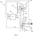
- FIG 2 shows a control structure 250 for cooling in a schematic representation.
- a wind turbine 200 is shown schematically therein, which is the wind turbine 100 of FIG figure 1 can match.
- This wind energy installation 200 is symbolically integrated into the control structure 250 .
- the wind energy installation 200 has a tower 202 with a nacelle 204 arranged thereon together with an aerodynamic rotor 206 .
- the aerodynamic rotor 206 drives a generator 201 which thereby produces power.
- the electrical power generated in this way, less the power consumed, can be fed into an electrical supply network 220 via a feed unit 205, usually via a transformer 216.
- a plant controller 203 can be provided to control the feed unit 205 and, if necessary, also to control other elements of the wind energy plant .
- the generator 201 and the feed unit 205 in particular can heat up during operation.
- the feed unit can have a converter or a converter unit, which is to be heated and, if necessary, cooled.
- a converter cooling system 255 for cooling the feed unit 205 and a generator cooling system 251 for cooling the generator 201 are therefore provided here as an example.
- a partial controller 233 can also be provided in the nacelle 204 for the generator 201 and the generator cooling system 251 and any other elements. However, any controls can also be bundled in the system control 203 .
- a DC chopper for example, can be considered as a further component to be cooled if the generator is an externally excited synchronous generator.
- the generator can be driven by a generator-side inverter, which can be part of the supply unit 205, or which can be a separate element and can also be a component to be cooled.
- various actuators can also form components that need to be cooled if they tend to get too hot during operation.
- corresponding temperature sensors are provided, namely here converter temperature sensor 235 on feed unit 205 and generator temperature sensor 231 on generator 201. Both temperatures, i.e. the converter temperature T INV of the feed unit or the converter unit contained therein and the generator temperature T G at the generator are thus detected and transmitted to a cooling controller 252 .
- the cooling controller 252 also receives an operation evaluation signal EV as at least one input variable.
- the cooling controller 252 determines a respective cooling control signal for the generator cooling system 251 and the converter cooling system 255, which can also be referred to as cooling of the infeed unit or infeed cooling system, namely a generator cooling control signal C G , which controls the generator cooling system 251, and a converter cooling control signal C INV , with which the Converter cooling 255 is controlled.
- the cooling controller 252 thus controls the cooling as a function of the relevant component temperature, ie here the generator temperature T G or the converter temperature T INV . In addition, the cooling is controlled depending on the operational evaluation.
- the operational evaluation can be performed in the plant controller 203, which the schematic control structure 250 indicates. However, the company evaluation can also be carried out elsewhere.
- the company evaluation can take various input variables into account, which is figure 2 is not shown for the sake of clarity. In particular, it can be evaluated whether the wind turbine is feeding in nominal power, whether the wind turbine is working in reduced-power operation, whether the wind turbine is working in inertial operation, whether a change, in particular a reduction in the power fed in is predicted, to name a few examples.
- the operational evaluation signal EV is then determined from the operational evaluations and this can contain the respective evaluation encoded as yes or no and possibly transmitted as 0 or 1.
- evaluations can also be considered that have a quantitative content, in particular the extent to which predicted changes are expected, such as the change in wind speed and/or output power and/or efficiency of the component to be cooled in each case.
- the evaluation signal EV can therefore also contain quantitative values.
- the activation of the individual cooling systems can be a switch-on or switch-off signal.
- a control in terms of height also comes into consideration.
- This can be particularly blowers, as they are also in the figure 2 are indicated for generator cooling 251 and converter cooling 255 can be controlled quantitatively.
- a speed setpoint can be given to the respective cooling system, ie to the respective fan.
- a circulating pump in the case of liquid cooling. This can also be controlled via a speed specification.
- the control signals for the components to be cooled can be the same.
- the generator control signal C G and the converter control signal C INV could then be the same and switch to the same criterion and thus at the same point in time.
- the generator cooling system 251 and the converter cooling system 255 therefore preferably each have different individual speed values.
- operating parameters of the wind energy installation can be taken into account, in particular operating parameters of the generator 201 and the feed unit 205 or a converter unit included in the feed unit 205 and/or another converter unit.
- Receiving an external signal, in particular a weather forecast, or at least a wind forecast comes into consideration for taking into account predicted variables or predicted situations. This is symbolized by the weather forecast block 260 which transmits corresponding weather forecasts or at least wind forecasts to the wind turbine 200 .
- a transmission to the system controller 203 is shown symbolically for this.
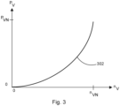
- FIG figure 3 shows an exemplary and illustrative speed-power curve as a load profile of a fan, for example the generator cooling system 251 of FIG figure 2 .
- a load profile of a pump of a liquid cooling system can also be designed in a similar way.
- the diagram thus shows the speed nv of the fan on the abscissa and the power Pv, which the fan consumes, on the ordinate.
- the rotational speed power characteristic curve 302 thus begins at 0, when the fan is switched off, that is to say the rotational speed is 0 and the power consumption is likewise. It extends up to a nominal speed n VN of the fan, which it ideally achieves at nominal power P VN of the fan.
- a cooling system of a component or a complex of components is, or has been, controlled mainly according to the temperature of this component. This is to avoid overheating.
- AEP annual energy production
- the control of the cooling system can be extended so that in certain cases (rated power, derated mode, inertia operation, etc.) more energy is produced compared to normal operation.
- this can serve to maximize the efficiency and thus the annual energy production (AEP) of a wind turbine.
- the code is being developed so that the same code is able to calculate the new stress profiles of fans/pumps to eliminate or minimize overstressing or component aging.
Landscapes
- Engineering & Computer Science (AREA)
- Life Sciences & Earth Sciences (AREA)
- Sustainable Development (AREA)
- Sustainable Energy (AREA)
- Chemical & Material Sciences (AREA)
- Combustion & Propulsion (AREA)
- Mechanical Engineering (AREA)
- General Engineering & Computer Science (AREA)
- Physics & Mathematics (AREA)
- Thermal Sciences (AREA)
- Power Engineering (AREA)
- Control Of Eletrric Generators (AREA)
Priority Applications (2)
| Application Number | Priority Date | Filing Date | Title |
|---|---|---|---|
| EP21206380.4A EP4177460A1 (fr) | 2021-11-04 | 2021-11-04 | Procédé de refroidissement efficace d'une éolienne |
| US17/980,989 US12018658B2 (en) | 2021-11-04 | 2022-11-04 | Method for efficiently cooling a wind power installation |
Applications Claiming Priority (1)
| Application Number | Priority Date | Filing Date | Title |
|---|---|---|---|
| EP21206380.4A EP4177460A1 (fr) | 2021-11-04 | 2021-11-04 | Procédé de refroidissement efficace d'une éolienne |
Publications (1)
| Publication Number | Publication Date |
|---|---|
| EP4177460A1 true EP4177460A1 (fr) | 2023-05-10 |
Family
ID=78528664
Family Applications (1)
| Application Number | Title | Priority Date | Filing Date |
|---|---|---|---|
| EP21206380.4A Pending EP4177460A1 (fr) | 2021-11-04 | 2021-11-04 | Procédé de refroidissement efficace d'une éolienne |
Country Status (2)
| Country | Link |
|---|---|
| US (1) | US12018658B2 (fr) |
| EP (1) | EP4177460A1 (fr) |
Citations (4)
| Publication number | Priority date | Publication date | Assignee | Title |
|---|---|---|---|---|
| EP2821642A1 (fr) * | 2013-07-01 | 2015-01-07 | Kabushiki Kaisha Yaskawa Denki | Système de génération d'énergie éolienne |
| US10151301B2 (en) * | 2013-01-25 | 2018-12-11 | Vestas Wind Systems A/S | Control of wind turbines |
| US20200011303A1 (en) * | 2018-07-03 | 2020-01-09 | Siemens Gamesa Renewable Energy A/S | Wind turbine and a method for operating a wind turbine |
| US20210190035A1 (en) * | 2019-12-20 | 2021-06-24 | Wobben Properties Gmbh | Method for determining the energy production of a wind power installation |
Family Cites Families (1)
| Publication number | Priority date | Publication date | Assignee | Title |
|---|---|---|---|---|
| EP3562002A1 (fr) * | 2018-04-24 | 2019-10-30 | Siemens Gamesa Renewable Energy A/S | Ventilateur de refroidissement pour éolienne |
-
2021
- 2021-11-04 EP EP21206380.4A patent/EP4177460A1/fr active Pending
-
2022
- 2022-11-04 US US17/980,989 patent/US12018658B2/en active Active
Patent Citations (4)
| Publication number | Priority date | Publication date | Assignee | Title |
|---|---|---|---|---|
| US10151301B2 (en) * | 2013-01-25 | 2018-12-11 | Vestas Wind Systems A/S | Control of wind turbines |
| EP2821642A1 (fr) * | 2013-07-01 | 2015-01-07 | Kabushiki Kaisha Yaskawa Denki | Système de génération d'énergie éolienne |
| US20200011303A1 (en) * | 2018-07-03 | 2020-01-09 | Siemens Gamesa Renewable Energy A/S | Wind turbine and a method for operating a wind turbine |
| US20210190035A1 (en) * | 2019-12-20 | 2021-06-24 | Wobben Properties Gmbh | Method for determining the energy production of a wind power installation |
Also Published As
| Publication number | Publication date |
|---|---|
| US12018658B2 (en) | 2024-06-25 |
| US20230132516A1 (en) | 2023-05-04 |
Similar Documents
| Publication | Publication Date | Title |
|---|---|---|
| EP2411669B2 (fr) | Procédé de fonctionnement d'une éolienne | |
| EP2457320B1 (fr) | Procédé de fonctionnement d'une turbine éolienne et turbine éolienne associée | |
| DE102006063094B4 (de) | System und Verfahren zum Betrieb eines Windparks bei hohen Windgeschwindigkeiten | |
| EP2556247B1 (fr) | Régulation d'inertie dynamique | |
| DE102008037449B4 (de) | Windenergieanlage | |
| EP2751422B1 (fr) | Procédé permettant de faire fonctionner une éolienne | |
| EP3533125B1 (fr) | Procédé de commande d'une installation électrique éolienne | |
| DE10320087A1 (de) | Verfahren zum Betreiben eines Windparks | |
| DE102011051416A1 (de) | Windkraftanlage und Verfahren zum Betrieb einer Windkraftanlage | |
| DE102010015595A1 (de) | Verfahren zum Betreiben einer Windenergieanlage | |
| EP3749851B1 (fr) | Procédé pour commander un aérogénérateur et aérogénérateur correspondant | |
| EP2284974A1 (fr) | Procédé de fonctionnement ou de réglage d'une éolienne et procédé de préparation de la puissance de régulation à l'aide d'une éolienne | |
| EP3444938B1 (fr) | Procédé de commande d'une éolienne | |
| EP3810924B1 (fr) | Fonctionnement à puissance réduite d'une éolienne | |
| EP3545599B1 (fr) | Procédé d'injection de puissance électrique dans un réseau de distribution électrique | |
| DE102013206119A1 (de) | Windenergieanlage und Verfahren zum Betreiben einer Windenergieanlage | |
| EP4177460A1 (fr) | Procédé de refroidissement efficace d'une éolienne | |
| EP4297229A2 (fr) | Générateurs basés sur un convertisseur et procédé d'alimentation en puissance électrique | |
| EP4421312A2 (fr) | Procédé de commande d'une éolienne | |
| EP3958425B1 (fr) | Générateurs basés sur un convertisseur et procédé d'alimentation en puissance électrique | |
| EP3848575B1 (fr) | Procédé de fonctionnement d'un parc éolien comprenant plusieurs éoliennes ainsi que parc éolien correspondant | |
| WO2012055702A1 (fr) | Procédé de mise à l'arrêt d'un turbogénérateur | |
| EP3931437B1 (fr) | Procédé servant à faire fonctionner une éolienne en cas de défaillance de réseau | |
| EP4390114B1 (fr) | Procédé de fonctionnement d'une éolienne à rendement accru | |
| DE102018201847A1 (de) | Verfahren zum Erwärmen eines Elektromotors, sowie Motorsystem und Ventilator |
Legal Events
| Date | Code | Title | Description |
|---|---|---|---|
| PUAI | Public reference made under article 153(3) epc to a published international application that has entered the european phase |
Free format text: ORIGINAL CODE: 0009012 |
|
| STAA | Information on the status of an ep patent application or granted ep patent |
Free format text: STATUS: THE APPLICATION HAS BEEN PUBLISHED |
|
| AK | Designated contracting states |
Kind code of ref document: A1 Designated state(s): AL AT BE BG CH CY CZ DE DK EE ES FI FR GB GR HR HU IE IS IT LI LT LU LV MC MK MT NL NO PL PT RO RS SE SI SK SM TR |
|
| STAA | Information on the status of an ep patent application or granted ep patent |
Free format text: STATUS: REQUEST FOR EXAMINATION WAS MADE |
|
| 17P | Request for examination filed |
Effective date: 20231110 |
|
| RBV | Designated contracting states (corrected) |
Designated state(s): AL AT BE BG CH CY CZ DE DK EE ES FI FR GB GR HR HU IE IS IT LI LT LU LV MC MK MT NL NO PL PT RO RS SE SI SK SM TR |
|
| STAA | Information on the status of an ep patent application or granted ep patent |
Free format text: STATUS: EXAMINATION IS IN PROGRESS |
|
| 17Q | First examination report despatched |
Effective date: 20250210 |