EP4177496A1 - Rouleau de commutation - Google Patents
Rouleau de commutation Download PDFInfo
- Publication number
- EP4177496A1 EP4177496A1 EP22203725.1A EP22203725A EP4177496A1 EP 4177496 A1 EP4177496 A1 EP 4177496A1 EP 22203725 A EP22203725 A EP 22203725A EP 4177496 A1 EP4177496 A1 EP 4177496A1
- Authority
- EP
- European Patent Office
- Prior art keywords
- cage
- shift drum
- carriage
- shift
- wall
- Prior art date
- Legal status (The legal status is an assumption and is not a legal conclusion. Google has not performed a legal analysis and makes no representation as to the accuracy of the status listed.)
- Granted
Links
Images


Classifications
-
- F—MECHANICAL ENGINEERING; LIGHTING; HEATING; WEAPONS; BLASTING
- F16—ENGINEERING ELEMENTS AND UNITS; GENERAL MEASURES FOR PRODUCING AND MAINTAINING EFFECTIVE FUNCTIONING OF MACHINES OR INSTALLATIONS; THERMAL INSULATION IN GENERAL
- F16H—GEARING
- F16H63/00—Control outputs from the control unit to change-speed- or reversing-gearings for conveying rotary motion or to other devices than the final output mechanism
- F16H63/02—Final output mechanisms therefor; Actuating means for the final output mechanisms
- F16H63/08—Multiple final output mechanisms being moved by a single common final actuating mechanism
- F16H63/16—Multiple final output mechanisms being moved by a single common final actuating mechanism the final output mechanisms being successively actuated by progressive movement of the final actuating mechanism
- F16H63/18—Multiple final output mechanisms being moved by a single common final actuating mechanism the final output mechanisms being successively actuated by progressive movement of the final actuating mechanism the final actuating mechanism comprising cams
-
- F—MECHANICAL ENGINEERING; LIGHTING; HEATING; WEAPONS; BLASTING
- F16—ENGINEERING ELEMENTS AND UNITS; GENERAL MEASURES FOR PRODUCING AND MAINTAINING EFFECTIVE FUNCTIONING OF MACHINES OR INSTALLATIONS; THERMAL INSULATION IN GENERAL
- F16H—GEARING
- F16H63/00—Control outputs from the control unit to change-speed- or reversing-gearings for conveying rotary motion or to other devices than the final output mechanism
- F16H63/02—Final output mechanisms therefor; Actuating means for the final output mechanisms
- F16H63/08—Multiple final output mechanisms being moved by a single common final actuating mechanism
- F16H63/10—Multiple final output mechanisms being moved by a single common final actuating mechanism the final actuating mechanism having a series of independent ways of movement, each way of movement being associated with only one final output mechanism
-
- F—MECHANICAL ENGINEERING; LIGHTING; HEATING; WEAPONS; BLASTING
- F16—ENGINEERING ELEMENTS AND UNITS; GENERAL MEASURES FOR PRODUCING AND MAINTAINING EFFECTIVE FUNCTIONING OF MACHINES OR INSTALLATIONS; THERMAL INSULATION IN GENERAL
- F16H—GEARING
- F16H63/00—Control outputs from the control unit to change-speed- or reversing-gearings for conveying rotary motion or to other devices than the final output mechanism
- F16H63/02—Final output mechanisms therefor; Actuating means for the final output mechanisms
- F16H63/30—Constructional features of the final output mechanisms
- F16H63/32—Gear shift yokes, e.g. shift forks
- F16H2063/321—Gear shift yokes, e.g. shift forks characterised by the interface between fork body and shift rod, e.g. fixing means, bushes, cams or pins
-
- F—MECHANICAL ENGINEERING; LIGHTING; HEATING; WEAPONS; BLASTING
- F16—ENGINEERING ELEMENTS AND UNITS; GENERAL MEASURES FOR PRODUCING AND MAINTAINING EFFECTIVE FUNCTIONING OF MACHINES OR INSTALLATIONS; THERMAL INSULATION IN GENERAL
- F16H—GEARING
- F16H63/00—Control outputs from the control unit to change-speed- or reversing-gearings for conveying rotary motion or to other devices than the final output mechanism
- F16H63/02—Final output mechanisms therefor; Actuating means for the final output mechanisms
- F16H63/30—Constructional features of the final output mechanisms
- F16H63/32—Gear shift yokes, e.g. shift forks
- F16H2063/322—Gear shift yokes, e.g. shift forks characterised by catches or notches for moving the fork
Definitions
- the present invention relates to a device for the axial movement of a transmission element according to the preamble of claim 1.
- the DE 89 12 348 U1 , the U.S.A. 4,782,782 and the DE 689 10 468 T2 each disclose a device according to the preamble of applicable claim 1. Also from U.S. 6,370,976 B1 a generic device is known.
- the object of the invention is to improve the known device.
- a device for the axial movement of a transmission element comprises a shift drum mounted rotatably about an axis of rotation with a shift groove formed circumferentially about the axis of rotation in its outer casing, which is at least partially axially inclined, a cage holding the shift drum with a cage interior against a cage exterior delimiting cage wall and an axially through the wall slot running along the cage wall, which opens the cage interior to the cage exterior, a carriage held axially movable between the shift drum and the cage wall in the area of the wall slot, and a shift fork with two fork legs, between which the transmission element can be positively accommodated for axial movement in the axial direction and one adjoining the fork legs adjoining guide mandrel, which is guided through the wall slot and the carriage and inserted into the switching groove.
- the shifting groove is molded into the shift drum with a closed curve.
- the device is based on the idea that the shift fork should move in directions other than the axial direction with as little play as possible.
- the shift forks in the device mentioned above are mounted via guide sleeves on shafts, which are designed to take up space in the axial direction.
- the specified device takes a different approach here and does not mount the shift fork on its own shaft but guides it between the shift drum itself and a cage in which the shift drum is held. In this way, the specified device can be designed to be very space-saving, even if the shift drum carries a larger number of shift forks, for example three or four.
- the shifting groove is formed elliptically into the shift drum. In this way, an endless loop is created for the shifting groove, via which all shifting states of the specified device can be set by rotating the shift drum endlessly.
- the axial ends of the shift drum are guided through the cage to the outside of the cage, with a drive shaft for rotating the shift drum being insertable in at least one of the axial ends in the circumferential direction about the axis of rotation.
- Connect means for turning the shift drum through simple Attaching axle elements Connect means for turning the shift drum.
- the shift drum is positively held in the cage in the region of its axial ends in and counter to the axial direction. In this way, an axial play of the shift drum is minimized, so that the switching states of the device can be precisely defined.
- the cage is made up of at least a first cage part and a second cage part, which can be separated in the axial direction.
- the cage can be constructed in a simple manner as a modular system, for example in the context of model construction.
- the two cage parts are connected to one another by means of a positive cage connection acting in the axial direction.
- the cage parts can be dismantled and reused, for example, in model building for alternative models.
- the positive cage fit includes latching hooks. In this way, the previously mentioned ability to be dismantled is achieved on the one hand, but also a secure cohesion of the two cage parts on the other.
- the carriage is guided in the slot in the axial direction with a carriage form fit acting in the circumferential direction about the axis of rotation.
- This slot allows the axial guiding effect, ie guiding in the axial direction and preventing other degrees of freedom, to be increased even further.
- the carriage has on its side directed towards the shift drum an im Cross section circular segment-shaped recess in which the shift drum is inserted.
- This cutout in the shape of a segment of a circle prevents movements of the carriage transversely to the axial direction to be guided and further increases the axial guiding effect.
- the carriage is held guided in the cage at its left and right end, viewed in the axial direction, in the axial direction. In this way, the axial guiding effect is increased even further.
- the device 10 is in 1 with four gear elements 12 of a superordinate gear shown only in parts in the form of a gear train 14 engaged.
- the movement variables are changed via gear wheels 16 which are held on shafts 18 so as to be rotatable in a circumferential direction 17 about the axis of rotation 8 .
- the shafts 18 have form-fitting elements 20 acting in the circumferential direction 17, which in 1 for the sake of clarity, not all shafts 18 are provided with their own reference numbers.
- the transmission elements 12 are held in a form-fitting manner on these form-fitting elements 20, so that the transmission elements 12 can move in the longitudinal direction 2 and thus in the direction of the axis of rotation 8, but cannot rotate in the circumferential direction 17.
- Each transmission element 12 is made up of two rings 22 arranged parallel to the axis of rotation 8 and spaced axially apart from one another and held concentrically to the respective shaft 18 , so that an axial slot 24 is formed between the rings 22 .
- the rings 22 of each gear member 12 are carried on coupling members 26 which are concentrically disposed within the rings 22 and are secured to the rings 22 by walls 28 .
- the respective coupling element 26 is positively connected to the form-fitting elements 20 of the respective shaft 18, so that the coupling element 26 rotates when the respective shaft 18 rotates. If the gear elements 12 on the respective Shafts 18 moved back and forth in the longitudinal direction 2, they can be positively engaged in the gears in the circumferential direction 17, so that by turning the respective shaft 18 not only the transmission element 12 but also the engaged gear is rotated.
- the structure and operation of the gear elements 12 is basically from the WO 2019 / 137 993 A1 known and will therefore not be further explored.
- device 10 is shown in perspective view engaged with a single gear element.
- the device 10 comprises a cylindrically constructed cage 30 with essentially square top surfaces 32 and a casing 34 connecting the top surfaces.
- the cage 30 is made of a first cage part 36 and a second cage part 38, the second cage part 38 being placed on the first cage part 36 as a cover. The connection between the two cage parts 36, 38 will be discussed in more detail later.
- Each carriage 42 has a slot-shaped insertion opening 44 directed towards the axis of rotation 8 and into which a fork 46 can be inserted. In the perspective and configuration of the 1 only one of the slit-shaped insertion openings 44 and of the insertable forks 46 can be seen.
- the top surfaces 32 and the jacket 34 of the cage 30 enclose a later in 4 referenced cage interior 48, in which a rotatable about the axis of rotation 8 shift drum 50 is accommodated.
- the shift drum 50 is through in 4 to be seen shift drum openings 51 in the top surfaces 32 of the cage 30 led out of the cage chin space 48 and has a cross-shaped insertion opening 52 on both end faces, into which a shaft 18 can be inserted, as has already been described above.
- In the perspective of 2 only one of the cross-shaped insertion openings 52 can be seen, with only one of the cross-shaped insertion openings 52 having a shaft 18 inserted therein. Further design details of the shift drum 50 will be discussed in detail later.
- the shift drum 50 can be rotated in and counter to the circumferential direction 17 via the shafts 18 that can be inserted into the cross-shaped insertion openings 52 . It is the task of the shift drum to convert this rotational movement into a linear movement 54 of the carriage 42, which moves the forks 46 with the linear movement 54. The forks 46 are in turn pushed into the axial slots 24 of the gear elements 12 in a form-fitting manner in the longitudinal direction 2 and can thus transmit the linear movement 54 to the gear elements 12 . In this way, the gear train 14 can be shifted in the manner explained above.
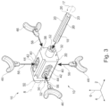
- the device 10 allows the gear train 14 to be modularly constructed with any number of gear wheels 16 between one and eight. This is based on 3 1 is a partially exploded perspective view of the device 10 of FIG 1 shows.
- a fork 46 can be accommodated in each slot-shaped insertion opening 44 in a corresponding insertion direction 56 directed towards the axis of rotation 8 , so that the device 10 guides up to four forks 46 .
- Each recorded fork 46 can then turn into a previously in connection with 2 engage gear element 12 described and switch either one gear 16 or two gears 16, depending on how many gears 16 are arranged on the respective shaft 18.
- between one and eight switching stages can be set up in any way with the device 10 .
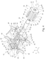
- FIG. 1 shows a fully exploded perspective view of the device 10.
- the shift drum 50 is the heart of the device 10. It has a drum body 58 which is placed rotationally symmetrically about the axis of rotation 8 and on the end faces of which shift drum journals 60 are placed rotationally symmetrically about the axis of rotation 8.
- the insertion openings 52 are formed in the axial end faces of these shift drum journals 60, which are opposite to the shift drum body 58 4 are not visible.
- the shift drum journals 60 have a smaller radius, viewed from the axis of rotation 8, than the shift drum body 58, so that at the axial ends of the shift drum body 58 an axial shift drum shoulder 61 is formed.
- the shift drum shoulders 61 can hit the shift drum openings 51 of the cage 30 for an axial form fit.
- the shift drum body 58 has a jacket, not further referenced, in which a shift groove 62 is formed.
- the shifting groove 62 In order to be able to move a fork 46 axially by rotating the shift drum 50 about the axis of rotation 8, the shifting groove 62 must run circumferentially around the axis of rotation 8 in the area of the fork to be shifted and with an angle of inclination 64 of greater than 0° and less than 90° be progressively trained.
- Individual shift grooves 62 can be formed in shift drum body 58 to move each fork 46 individually. In the 4 shown common switching groove 62 is only a preferred embodiment.
- the switching groove 62 can be open in a manner not shown with a beginning and a not shown not shown End in the shift drum body 58, for example, be formed spirally.
- the 4 shown closed embodiment of the switching groove 62 with a basically elliptical profile is only a preferred embodiment.
- this has the decisive advantage that the switching groove can be produced without an undercut and on an in 4 indicated dividing line 66 can be separated into a switching groove upper part and switching groove lower part, on which two injection molds can be brought together.
- each carriage 42 seen from the axis of rotation 8 , has a bearing surface 66 on its underside, which is designed in the shape of a segment of a circle in a cross-section running at right angles to the axis of rotation 8 through the respective carriage 42 .
- the circle segment has a radius that is equal to the radius of the shift drum body 58 . In this way, the carriage is guided on the shift drum body 58 with as little tolerance as possible.
- each carriage 42 optionally has a carriage positive-locking element 68 on its sides seen in the circumferential direction 17, which in the embodiment of FIG 4 designed as a semi-circular rod and held on the sled base body, which is not further referenced.
- the cage 30 has corresponding carriage guide elements 70, into which the carriage form-locking elements 68 can be inserted, so that the carriage can be guided back and forth in the longitudinal direction 2.
- carriage guide elements 70 are in the perspective of 4 not see all present in the cage 30.
- projections 72 can be formed on the carriages 42 which can be positively inserted into the slots 40 in and counter to the circumferential direction 17 .
- the projections 72 should be circular or elliptical at least in the area of contact with the walls of their respective slot 40 to minimize contact friction.
- the slit-shaped insertion openings 44 through the carriage 42 change in cross section and thus have support shoulders 74, of which in the perspective of 4 only two can be seen.
- Support elements 76 held on the forks 46 can be placed on these support shoulders 74, between which a guide mandrel 78 is held in each fork 46.
- Two fork legs 80 each connect to each guide mandrel 78 .
- the two cage parts 36, 38 each have four latching hooks 82, each with a non-referenced hook form-fitting surface, which is directed towards the top surface 32 of the respective cage part 36, 38.
- the latching hooks 82 are each held in a groove 84 on the second cage part 38 and extend over the entire length of the second cage part 38 in the longitudinal direction 2 .
- the grooves 84 open the hook form-fitting surfaces of the latching hooks 82 on the second cage part 38 in the longitudinal direction, so that the second cage part 38 can be manufactured together with the latching hooks 82 without a slide using a primary molding process such as injection molding.
- the carriage 42 with their carriage form-fitting elements 68 in the carriage guide elements 70 on the second cage part 38.
- the shift drum body 58 with one of the shift drum pivots 60 is then introduced into the passage formed by the contact surfaces 66 of the carriage 42, the shift drum pivot 60 being inserted through the Shift drum opening 51 is passed to the outside on the second cage part 38 .
- the first cage part 36 is placed on the second cage part 38 in the longitudinal direction 2 and the latching hooks 82 are hooked together.
- the shift forks 46 can now be inserted with their guide pins 78 into the slot-shaped insertion openings 44 .
- each guide mandrel 78 used ends in the switching groove 62 in order to ensure the switching function mentioned above.
Landscapes
- Engineering & Computer Science (AREA)
- General Engineering & Computer Science (AREA)
- Mechanical Engineering (AREA)
- Gear-Shifting Mechanisms (AREA)
Applications Claiming Priority (1)
| Application Number | Priority Date | Filing Date | Title |
|---|---|---|---|
| DE102021128917.3A DE102021128917B3 (de) | 2021-11-05 | 2021-11-05 | Schaltwalze |
Publications (3)
| Publication Number | Publication Date |
|---|---|
| EP4177496A1 true EP4177496A1 (fr) | 2023-05-10 |
| EP4177496C0 EP4177496C0 (fr) | 2025-08-20 |
| EP4177496B1 EP4177496B1 (fr) | 2025-08-20 |
Family
ID=82702713
Family Applications (1)
| Application Number | Title | Priority Date | Filing Date |
|---|---|---|---|
| EP22203725.1A Active EP4177496B1 (fr) | 2021-11-05 | 2022-10-26 | Rouleau de commutation |
Country Status (3)
| Country | Link |
|---|---|
| US (1) | US12018751B2 (fr) |
| EP (1) | EP4177496B1 (fr) |
| DE (1) | DE102021128917B3 (fr) |
Cited By (1)
| Publication number | Priority date | Publication date | Assignee | Title |
|---|---|---|---|---|
| EP4686859A3 (fr) * | 2024-07-31 | 2026-02-18 | Cummins Inc. | Appareil et procédés de tambour de changement de vitesse à piste unique |
Families Citing this family (3)
| Publication number | Priority date | Publication date | Assignee | Title |
|---|---|---|---|---|
| DE102022109199B4 (de) | 2022-04-14 | 2024-01-25 | Schaeffler Technologies AG & Co. KG | Schiebevorrichtung und Vorrichtung zum Koppeln und Entkoppeln zweier Wellen sowie elektrische Achsantriebsvorrichtung für ein hybrides oder elektrisches Fahrzeug |
| DE102022109198B4 (de) | 2022-04-14 | 2024-02-01 | Schaeffler Technologies AG & Co. KG | Schiebevorrichtung und Vorrichtung zum Koppeln und Entkoppeln zweier Wellen und elektrische Achsantriebsvorrichtung für ein hybrides oder elektrisches Fahrzeug |
| EP4569247A1 (fr) | 2022-08-09 | 2025-06-18 | Sew-Eurodrive GmbH & Co. KG | Dispositif de changement de vitesse et mécanisme d'engrenage comprenant un dispositif de changement de vitesse |
Citations (8)
| Publication number | Priority date | Publication date | Assignee | Title |
|---|---|---|---|---|
| US2577019A (en) * | 1947-08-13 | 1951-12-04 | Kesterton Henry Martin | Control mechanism for variablespeed gears or other purposes |
| US4782782A (en) | 1987-10-26 | 1988-11-08 | General Motors Corporation | Transmission position indicator mechanism |
| DE8912348U1 (de) | 1989-10-18 | 1989-12-07 | Expert Maschinenbau Gmbh, 6143 Lorsch | Schrittantriebsvorrichtung |
| DE68910468T2 (de) | 1988-10-26 | 1994-03-03 | Emerson Electric Co | Nockenlinearantriebseinheit. |
| US6370976B1 (en) | 1997-06-28 | 2002-04-16 | INA Wälzlager Schaeffler oHG | Gear shifting drum for a variable-speed gearbox |
| JP2012072829A (ja) * | 2010-09-28 | 2012-04-12 | Univance Corp | シフトフォーク |
| CN106609842A (zh) * | 2017-01-12 | 2017-05-03 | 西南大学 | 换挡机构、变速箱及电动车 |
| WO2019137993A1 (fr) | 2018-01-11 | 2019-07-18 | Lego A/S | Boîte de vitesses pour jouet |
-
2021
- 2021-11-05 DE DE102021128917.3A patent/DE102021128917B3/de active Active
-
2022
- 2022-10-26 EP EP22203725.1A patent/EP4177496B1/fr active Active
- 2022-11-04 US US17/981,137 patent/US12018751B2/en active Active
Patent Citations (8)
| Publication number | Priority date | Publication date | Assignee | Title |
|---|---|---|---|---|
| US2577019A (en) * | 1947-08-13 | 1951-12-04 | Kesterton Henry Martin | Control mechanism for variablespeed gears or other purposes |
| US4782782A (en) | 1987-10-26 | 1988-11-08 | General Motors Corporation | Transmission position indicator mechanism |
| DE68910468T2 (de) | 1988-10-26 | 1994-03-03 | Emerson Electric Co | Nockenlinearantriebseinheit. |
| DE8912348U1 (de) | 1989-10-18 | 1989-12-07 | Expert Maschinenbau Gmbh, 6143 Lorsch | Schrittantriebsvorrichtung |
| US6370976B1 (en) | 1997-06-28 | 2002-04-16 | INA Wälzlager Schaeffler oHG | Gear shifting drum for a variable-speed gearbox |
| JP2012072829A (ja) * | 2010-09-28 | 2012-04-12 | Univance Corp | シフトフォーク |
| CN106609842A (zh) * | 2017-01-12 | 2017-05-03 | 西南大学 | 换挡机构、变速箱及电动车 |
| WO2019137993A1 (fr) | 2018-01-11 | 2019-07-18 | Lego A/S | Boîte de vitesses pour jouet |
Cited By (1)
| Publication number | Priority date | Publication date | Assignee | Title |
|---|---|---|---|---|
| EP4686859A3 (fr) * | 2024-07-31 | 2026-02-18 | Cummins Inc. | Appareil et procédés de tambour de changement de vitesse à piste unique |
Also Published As
| Publication number | Publication date |
|---|---|
| EP4177496C0 (fr) | 2025-08-20 |
| DE102021128917B3 (de) | 2022-08-25 |
| US20230141361A1 (en) | 2023-05-11 |
| EP4177496B1 (fr) | 2025-08-20 |
| US12018751B2 (en) | 2024-06-25 |
Similar Documents
| Publication | Publication Date | Title |
|---|---|---|
| DE102021128917B3 (de) | Schaltwalze | |
| DE2502052C2 (de) | Schraubgetriebe zur Erzeugung einer geradlinigen Bewegung | |
| DE4024319C2 (de) | Vorrichtung zur Kupplung eines an einer Taumelscheibe drehbar abgestützten Ringkörpers mit Kolben in einem drehbaren Zylinderblock | |
| EP1236929B1 (fr) | Engrenage planétaire | |
| DE10304124A1 (de) | Differentialgetriebeeinheit | |
| CH655247A5 (de) | Vorrichtung zur loesbaren verbindung einer mehrzahl laenglicher bauelemente. | |
| DE10236158A1 (de) | Gelenk, insbesondere für Liegen | |
| DE19545032C2 (de) | Differentialgetriebe | |
| DE2245437B2 (de) | Kugellager für Längs- und Drehbewegungen | |
| DE69506123T2 (de) | Ein getriebe aufweisender bausatz | |
| DE3048341C2 (de) | Winkelbewegliche Gelenkkupplung | |
| DE4217784A1 (de) | Differentialgetriebe | |
| DE69400764T2 (de) | Mechanismus zur Umwandlung einer drehenden in eine geradlinige Bewegung | |
| DD284065A5 (de) | Legebarrenlagerung fuer kettenwirkmaschinen | |
| DE3343826C2 (fr) | ||
| DE3635827A1 (de) | Fuehrungskette fuer die zur bandabstuetzung im pressbereich vorgesehenen rollen einer doppelbandpresse | |
| DE2019506C3 (de) | Kugellager für axiale Bewegungen bezüglich einer Welle | |
| DE3710518C1 (de) | Drehgelenk fuer kleine Beugewinkel | |
| EP2150716B1 (fr) | Embrayage | |
| DE2841279B1 (de) | Rotations-Schaftmaschine | |
| DE9402519U1 (de) | Kupplungseinrichtung in einem Doppelschließzylinder mit Gefahrenfunktion | |
| DE102020117174B3 (de) | Rollschuh- Vor und Nachlaufrollen | |
| EP1988311A2 (fr) | Palier et actionneur linéaire équipé d'un tel palier | |
| DE4237463C2 (de) | Ausgleichsgetriebe | |
| DE1966974U (de) | Kugel-segmentlagerung. |
Legal Events
| Date | Code | Title | Description |
|---|---|---|---|
| PUAI | Public reference made under article 153(3) epc to a published international application that has entered the european phase |
Free format text: ORIGINAL CODE: 0009012 |
|
| STAA | Information on the status of an ep patent application or granted ep patent |
Free format text: STATUS: THE APPLICATION HAS BEEN PUBLISHED |
|
| AK | Designated contracting states |
Kind code of ref document: A1 Designated state(s): AL AT BE BG CH CY CZ DE DK EE ES FI FR GB GR HR HU IE IS IT LI LT LU LV MC ME MK MT NL NO PL PT RO RS SE SI SK SM TR |
|
| STAA | Information on the status of an ep patent application or granted ep patent |
Free format text: STATUS: REQUEST FOR EXAMINATION WAS MADE |
|
| 17P | Request for examination filed |
Effective date: 20231110 |
|
| RBV | Designated contracting states (corrected) |
Designated state(s): AL AT BE BG CH CY CZ DE DK EE ES FI FR GB GR HR HU IE IS IT LI LT LU LV MC ME MK MT NL NO PL PT RO RS SE SI SK SM TR |
|
| RIC1 | Information provided on ipc code assigned before grant |
Ipc: F16H 63/32 20060101ALI20250218BHEP Ipc: F16H 63/18 20060101AFI20250218BHEP |
|
| GRAP | Despatch of communication of intention to grant a patent |
Free format text: ORIGINAL CODE: EPIDOSNIGR1 |
|
| STAA | Information on the status of an ep patent application or granted ep patent |
Free format text: STATUS: GRANT OF PATENT IS INTENDED |
|
| INTG | Intention to grant announced |
Effective date: 20250328 |
|
| GRAS | Grant fee paid |
Free format text: ORIGINAL CODE: EPIDOSNIGR3 |
|
| GRAA | (expected) grant |
Free format text: ORIGINAL CODE: 0009210 |
|
| STAA | Information on the status of an ep patent application or granted ep patent |
Free format text: STATUS: THE PATENT HAS BEEN GRANTED |
|
| AK | Designated contracting states |
Kind code of ref document: B1 Designated state(s): AL AT BE BG CH CY CZ DE DK EE ES FI FR GB GR HR HU IE IS IT LI LT LU LV MC ME MK MT NL NO PL PT RO RS SE SI SK SM TR |
|
| REG | Reference to a national code |
Ref country code: GB Ref legal event code: FG4D Free format text: NOT ENGLISH |
|
| REG | Reference to a national code |
Ref country code: CH Ref legal event code: EP |
|
| REG | Reference to a national code |
Ref country code: DE Ref legal event code: R096 Ref document number: 502022005110 Country of ref document: DE |
|
| REG | Reference to a national code |
Ref country code: IE Ref legal event code: FG4D Free format text: LANGUAGE OF EP DOCUMENT: GERMAN |
|
| U01 | Request for unitary effect filed |
Effective date: 20250918 |
|
| U07 | Unitary effect registered |
Designated state(s): AT BE BG DE DK EE FI FR IT LT LU LV MT NL PT RO SE SI Effective date: 20250925 |
|
| REG | Reference to a national code |
Ref country code: CH Ref legal event code: U11 Free format text: ST27 STATUS EVENT CODE: U-0-0-U10-U11 (AS PROVIDED BY THE NATIONAL OFFICE) Effective date: 20251101 |
|
| U20 | Renewal fee for the european patent with unitary effect paid |
Year of fee payment: 4 Effective date: 20251204 |
|
| PG25 | Lapsed in a contracting state [announced via postgrant information from national office to epo] |
Ref country code: IS Free format text: LAPSE BECAUSE OF FAILURE TO SUBMIT A TRANSLATION OF THE DESCRIPTION OR TO PAY THE FEE WITHIN THE PRESCRIBED TIME-LIMIT Effective date: 20251220 |
|
| PG25 | Lapsed in a contracting state [announced via postgrant information from national office to epo] |
Ref country code: NO Free format text: LAPSE BECAUSE OF FAILURE TO SUBMIT A TRANSLATION OF THE DESCRIPTION OR TO PAY THE FEE WITHIN THE PRESCRIBED TIME-LIMIT Effective date: 20251120 |
|
| PG25 | Lapsed in a contracting state [announced via postgrant information from national office to epo] |
Ref country code: HR Free format text: LAPSE BECAUSE OF FAILURE TO SUBMIT A TRANSLATION OF THE DESCRIPTION OR TO PAY THE FEE WITHIN THE PRESCRIBED TIME-LIMIT Effective date: 20250820 |
|
| PG25 | Lapsed in a contracting state [announced via postgrant information from national office to epo] |
Ref country code: GR Free format text: LAPSE BECAUSE OF FAILURE TO SUBMIT A TRANSLATION OF THE DESCRIPTION OR TO PAY THE FEE WITHIN THE PRESCRIBED TIME-LIMIT Effective date: 20251121 |
|
| PGFP | Annual fee paid to national office [announced via postgrant information from national office to epo] |
Ref country code: CH Payment date: 20251101 Year of fee payment: 4 |
|
| PG25 | Lapsed in a contracting state [announced via postgrant information from national office to epo] |
Ref country code: PL Free format text: LAPSE BECAUSE OF FAILURE TO SUBMIT A TRANSLATION OF THE DESCRIPTION OR TO PAY THE FEE WITHIN THE PRESCRIBED TIME-LIMIT Effective date: 20250820 |
|
| PG25 | Lapsed in a contracting state [announced via postgrant information from national office to epo] |
Ref country code: RS Free format text: LAPSE BECAUSE OF FAILURE TO SUBMIT A TRANSLATION OF THE DESCRIPTION OR TO PAY THE FEE WITHIN THE PRESCRIBED TIME-LIMIT Effective date: 20251120 |
|
| PG25 | Lapsed in a contracting state [announced via postgrant information from national office to epo] |
Ref country code: ES Free format text: LAPSE BECAUSE OF FAILURE TO SUBMIT A TRANSLATION OF THE DESCRIPTION OR TO PAY THE FEE WITHIN THE PRESCRIBED TIME-LIMIT Effective date: 20250820 |
|
| PG25 | Lapsed in a contracting state [announced via postgrant information from national office to epo] |
Ref country code: SM Free format text: LAPSE BECAUSE OF FAILURE TO SUBMIT A TRANSLATION OF THE DESCRIPTION OR TO PAY THE FEE WITHIN THE PRESCRIBED TIME-LIMIT Effective date: 20250820 |
|
| PG25 | Lapsed in a contracting state [announced via postgrant information from national office to epo] |
Ref country code: CZ Free format text: LAPSE BECAUSE OF FAILURE TO SUBMIT A TRANSLATION OF THE DESCRIPTION OR TO PAY THE FEE WITHIN THE PRESCRIBED TIME-LIMIT Effective date: 20250820 |
|
| PG25 | Lapsed in a contracting state [announced via postgrant information from national office to epo] |
Ref country code: SK Free format text: LAPSE BECAUSE OF FAILURE TO SUBMIT A TRANSLATION OF THE DESCRIPTION OR TO PAY THE FEE WITHIN THE PRESCRIBED TIME-LIMIT Effective date: 20250820 |