EP4177555B1 - Agencement de porte à scories et procédé de nettoyage - Google Patents
Agencement de porte à scories et procédé de nettoyage Download PDFInfo
- Publication number
- EP4177555B1 EP4177555B1 EP21206173.3A EP21206173A EP4177555B1 EP 4177555 B1 EP4177555 B1 EP 4177555B1 EP 21206173 A EP21206173 A EP 21206173A EP 4177555 B1 EP4177555 B1 EP 4177555B1
- Authority
- EP
- European Patent Office
- Prior art keywords
- slag
- slag door
- tunnel
- door
- furnace
- Prior art date
- Legal status (The legal status is an assumption and is not a legal conclusion. Google has not performed a legal analysis and makes no representation as to the accuracy of the status listed.)
- Active
Links
Images



Classifications
-
- F—MECHANICAL ENGINEERING; LIGHTING; HEATING; WEAPONS; BLASTING
- F27—FURNACES; KILNS; OVENS; RETORTS
- F27D—DETAILS OR ACCESSORIES OF FURNACES, KILNS, OVENS OR RETORTS, IN SO FAR AS THEY ARE OF KINDS OCCURRING IN MORE THAN ONE KIND OF FURNACE
- F27D1/00—Casings; Linings; Walls; Roofs
- F27D1/18—Door frames; Doors, lids or removable covers
- F27D1/1858—Doors
-
- F—MECHANICAL ENGINEERING; LIGHTING; HEATING; WEAPONS; BLASTING
- F27—FURNACES; KILNS; OVENS; RETORTS
- F27B—FURNACES, KILNS, OVENS OR RETORTS IN GENERAL; OPEN SINTERING OR LIKE APPARATUS
- F27B3/00—Hearth-type furnaces, e.g. of reverberatory type; Electric arc furnaces ; Tank furnaces
- F27B3/10—Details, accessories or equipment, e.g. dust-collectors, specially adapted for hearth-type furnaces
-
- F—MECHANICAL ENGINEERING; LIGHTING; HEATING; WEAPONS; BLASTING
- F27—FURNACES; KILNS; OVENS; RETORTS
- F27D—DETAILS OR ACCESSORIES OF FURNACES, KILNS, OVENS OR RETORTS, IN SO FAR AS THEY ARE OF KINDS OCCURRING IN MORE THAN ONE KIND OF FURNACE
- F27D25/00—Devices or methods for removing incrustations, e.g. slag, metal deposits, dust; Devices or methods for preventing the adherence of slag
- F27D25/001—Devices or methods for removing incrustations, e.g. slag, metal deposits, dust; Devices or methods for preventing the adherence of slag comprising breaking tools, e.g. hammers, drills, scrapers
-
- F—MECHANICAL ENGINEERING; LIGHTING; HEATING; WEAPONS; BLASTING
- F27—FURNACES; KILNS; OVENS; RETORTS
- F27D—DETAILS OR ACCESSORIES OF FURNACES, KILNS, OVENS OR RETORTS, IN SO FAR AS THEY ARE OF KINDS OCCURRING IN MORE THAN ONE KIND OF FURNACE
- F27D3/00—Charging; Discharging; Manipulation of charge
- F27D3/15—Tapping equipment; Equipment for removing or retaining slag
- F27D3/1545—Equipment for removing or retaining slag
- F27D3/1554—Equipment for removing or retaining slag for removing the slag from the surface of the melt
- F27D3/1563—Equipment for removing or retaining slag for removing the slag from the surface of the melt by the use of scrapers
-
- F—MECHANICAL ENGINEERING; LIGHTING; HEATING; WEAPONS; BLASTING
- F27—FURNACES; KILNS; OVENS; RETORTS
- F27D—DETAILS OR ACCESSORIES OF FURNACES, KILNS, OVENS OR RETORTS, IN SO FAR AS THEY ARE OF KINDS OCCURRING IN MORE THAN ONE KIND OF FURNACE
- F27D1/00—Casings; Linings; Walls; Roofs
- F27D1/18—Door frames; Doors, lids or removable covers
- F27D1/1858—Doors
- F27D2001/1875—Hanging doors and walls
-
- F—MECHANICAL ENGINEERING; LIGHTING; HEATING; WEAPONS; BLASTING
- F27—FURNACES; KILNS; OVENS; RETORTS
- F27D—DETAILS OR ACCESSORIES OF FURNACES, KILNS, OVENS OR RETORTS, IN SO FAR AS THEY ARE OF KINDS OCCURRING IN MORE THAN ONE KIND OF FURNACE
- F27D2201/00—Manipulation of furnace parts
-
- Y—GENERAL TAGGING OF NEW TECHNOLOGICAL DEVELOPMENTS; GENERAL TAGGING OF CROSS-SECTIONAL TECHNOLOGIES SPANNING OVER SEVERAL SECTIONS OF THE IPC; TECHNICAL SUBJECTS COVERED BY FORMER USPC CROSS-REFERENCE ART COLLECTIONS [XRACs] AND DIGESTS
- Y02—TECHNOLOGIES OR APPLICATIONS FOR MITIGATION OR ADAPTATION AGAINST CLIMATE CHANGE
- Y02P—CLIMATE CHANGE MITIGATION TECHNOLOGIES IN THE PRODUCTION OR PROCESSING OF GOODS
- Y02P10/00—Technologies related to metal processing
- Y02P10/20—Recycling
Definitions
- the invention relates to a slag door arrangement for a metallurgical furnace and a method for cleaning the slag opening of a metallurgical furnace.
- Metallurgical furnaces such as electric arc furnaces are, for example, EP 0 385 434 A2 (Family member US$5,153,894 ) or the US$4,679,773 known.
- Electric arc furnaces are available in various designs in relation to the design of the tapping.
- Tapping refers to the process of letting the liquid steel flow out or pouring it out of the melting vessel during steel production and refers to the corresponding design of the metallurgical melting vessel as a device.
- ELBOs can have a tapping spout or a tap hole or a combination of these such as a submerged tap hole.
- ELBOs with tap holes such as ELBOs with a centric bottom tapping (CBT), with an offset bottom tapping (OBT), or with an eccentric bottom tapping (EBT).
- CBT centric bottom tapping
- OBT offset bottom tapping
- EBT eccentric bottom tapping
- the lower furnace vessel In an ELBO with OBT, the lower furnace vessel is circular and the tap hole is offset from the center.
- the lower furnace vessel has a bay window in which the tap hole is located.
- Slag consists of molten, usually non-metallic substances that are lighter than the molten metal in the metal bath. and therefore float on the metal bath.
- the term slag also covers solid substances that are lighter than the molten metal in the metal bath and therefore float on the metal bath, although these solid substances are strictly speaking referred to as dross in metallurgy.
- a slag layer has, among other things, the function of thermal shielding (insulation) for the metal bath.
- the slag opening or tunnel in the side wall of the furnace vessel is closed with a slag door for most of a melting process.
- the closure has several effects, including saving energy, preventing loss of metal and/or slag, and protecting the operating personnel.
- Slag door arrangements for closing the slag tunnel of a metallurgical furnace are known in the art.
- a slag door arrangement with three door parts is known.
- a first upper part of the slag door arrangement can be pivoted about a horizontal axis, which is located outside the furnace vessel and above the slag tunnel, between a closed position in the slag tunnel and an open position outside and above the slag tunnel.
- a second and a third lower part of the slag door arrangement can be pivoted about a vertical axis, which are located outside the furnace vessel and laterally to the right or left of the slag tunnel, between a closed position in the slag tunnel and an open position outside and laterally to the right or left of the slag tunnel.
- a slag door arrangement with two door parts is known.
- a first upper part and a second lower part of the slag door arrangement can be moved linearly outside the furnace vessel between a closed position and an open position outside and above the slag opening.
- the second lower part of the slag door arrangement can be moved linearly along the floor of the slag opening and the slag tunnel into the furnace in the closed position.
- Objects located on the floor of the slag opening and the slag tunnel, such as slag residues are pushed through the slag tunnel into the furnace.
- the floor of the slag tunnel is cleaned of slag residues by means of a linear movement from outside the furnace through the slag tunnel into the furnace.
- a slag door arrangement is known in which a slag door unit can be pivoted about a horizontal axis, which is located outside the furnace vessel and above the slag tunnel, between a closed position in the slag tunnel and an open position outside and above the slag tunnel.
- Objects located on the floor of the slag opening and the slag tunnel, such as slag residues, are pushed into the slag tunnel and possibly into the furnace. Cleaning the floor of the slag tunnel of slag residues by means of a pivoting movement from outside the furnace into the slag tunnel.
- a slag door arrangement according to the preamble of claim 1 is known, in which the slag door closes the slag tunnel from the outside and the slag door lifter is attached to the furnace vessel and the slag door swivel is attached to the slag door lifter.
- the ES 2 568 519 A1 and the US2001/0048187 A1 reveal other slag door arrangements.
- the object of the invention is to provide an improved slag door arrangement for a metallurgical furnace and an improved method for cleaning the slag opening of a metallurgical furnace.
- the slag door arrangement according to claim 1 enables a reliable sealing of the slag opening or the slag tunnel of a metallurgical furnace during the melting process combined with an improved cleaning of the slag opening or the slag tunnel by a cleaning movement of the slag door starting from a position in the slag tunnel near the inside of the furnace towards the outside of the furnace out of the slag tunnel.
- the method according to claim 12 enables improved cleaning of the slag opening or the slag tunnel of a metallurgical furnace by a cleaning movement of the slag door starting from a position in the slag tunnel near the inside of the furnace towards the outside of the furnace out of the slag tunnel.
- this movement can be carried out several times at different distances from the bottom of the slag opening or the slag tunnel.
- the pivoting movement of the slag door about a horizontal pivot axis and the linear movement of the slag door in a direction perpendicular to the horizontal pivot axis which are independent of each other, enable control of the cleaning movement of the slag door starting from a position in the slag tunnel near the inside of the furnace towards the outside of the furnace out of the slag tunnel at controllably different distances from the bottom of the slag opening or the slag tunnel.
- Fig.8 shows in a) components of a typical conventional electric arc furnace (ELBO) in an exploded view, in b) the ELBO from a) in a side view from the slag door side, and in c) the ELBO from a) in a plan view.
- ELBO electric arc furnace
- the ELBO 1 from Fig.8 has a furnace vessel 2 with a furnace bottom vessel 2a, a furnace top vessel 2b and a furnace cover 2c.
- the furnace vessel 2 is tiltable via a furnace tilting device with a furnace cradle 3 and a hydraulic cylinder 4 on a foundation 5 shown only schematically and thus mounted on the floor 6.
- a slag door 7 is arranged on one side in the side wall 2s of the furnace vessel 2. This side is referred to below as the slag door side S.
- the ELBO 1 has an eccentric bottom tap (EBT) in a bay window 2e of the furnace bottom vessel 2a on a side opposite the slag door side S, which is referred to below as the tapping side A and which in Fig. 8 c) shown above.
- EBT eccentric bottom tap
- the furnace bottom vessel 2a has an outer shell that is lined with refractory material (lining).
- the EBT has a tap hole (not shown) that extends through the furnace bottom vessel 2a, i.e. through the outer shell and the lining. During melting and before tapping, the tap hole is closed with a slide (not shown) on the underside of the furnace bottom vessel 2a and filled with a refractory filling material.
- a coordinate system xyz is shown.
- the direction x in the ELBO points horizontally from the slag door side S to the tapping side A.
- the direction y points horizontally from the slag door side S from right to left, here from the side K on which an exhaust manifold 71 is attached to the furnace cover 2c, to the side on which a portal 60 is located.
- the direction z is perpendicular to x and y from the plane of the paper and thus perpendicular to the floor from bottom to top.
- the bay window 10 projects in the x-direction over the circumference of the upper furnace vessel 2b.
- the ELBO shown is an ELBO operated with alternating current and has three electrodes 1e, which during operation protrude through the furnace lid 2c into the furnace vessel.
- the electrodes 1e are attached to electrode support arms 61, which are connected to a portal (lifting and swivel device) 60.
- Fig. 8 b) the ELBO from a) is shown in a side view from the slag door side S in a horizontal position in which the cover 2c is raised by means of the portal 60.
- the furnace vessel 2 is in Fig. 8 b) and c) shown in a horizontal (not tilted) position. In the position in Fig. 8 b) the electrodes 1e are pulled out of the cover 2c.
- the furnace vessel 2 is tilted by means of the furnace tilting device 3, 4 about a tilting axis parallel to the y-axis.
- a slag door arrangement 10 according to the present teachings can be retrofitted in conventional metallurgical furnaces or provided in new metallurgical furnaces.
- a slag door arrangement 10 according to the present teachings can be used, for example, in such a conventional ELBO 1 made of Fig.8 be installed instead of the slag door 7.
- the slag door arrangement 10 can be retrofitted in conventional ELBOs or provided in new ELBOs.
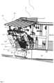
- FIG. 1 shows a partial view of an ELBO with a first embodiment of a slag door arrangement 10 in a side perspective view from the left front outside the ELBO with the slag door open
- Fig. 2 shows a partial view of the ELBO with the first embodiment of a slag door arrangement from Fig.1 in a side perspective view from the right front outside the ELBO with the slag door closed
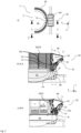
- the Fig. 3 to 5 show partial views of an ELBO with the first embodiment of the slag door assembly 10 various plan views, sectional views and side views previously described.
- the ELBO 1 from Fig. 1 to 5 indicates the Fig.8 shown and to Fig.8
- the coordinate system xyz from Fig.8 and the corresponding directions also apply to the Fig. 1 to 7 and the description of the invention.
- a furnace vessel 2 with a furnace bottom vessel 2a and a furnace top vessel 2b are shown.
- the furnace lid 2c, the electrodes 1e, the portal 60, the furnace tilting device with furnace cradle 3 and hydraulic cylinder 4, the foundation 5, the floor 6, the EBT, etc. are made of Fig.8 are in the partial views in Fig. 1 to 5 not shown.
- a first embodiment of a slag door arrangement 10 is arranged on one side in the side wall 2s of the furnace vessel 2. This side is again referred to below as the slag door side S.
- the furnace vessel 2 is in Fig. 1 to 4 shown in a horizontal (not tilted) position.
- the furnace vessel 2 can be tilted by means of the furnace tilting device 3, 4 about a tilting axis parallel to the y-axis.
- Fig.5 shows a position tilted by the angle ⁇ for deslagging.
- the furnace vessel 2 has a slag tunnel 8 with a rectangular opening cross-section, which is provided laterally in the furnace vessel 2.
- the slag tunnel 8 has side walls 8s, an upper outer edge 8or and a base 8b.
- the upper outer edge 8or runs horizontally when the furnace vessel is in a horizontal position and limits the rectangular opening cross-section at the top.
- the side walls 8s each extend at a right angle to the upper outer edge 8or and the base 8b.
- the slag door arrangement 10 has a plate-like slag door 11, the width of which corresponds to the width of the rectangular opening cross-section of the slag tunnel 8 with a clearance s that allows movement of the slag door 11 in the slag tunnel 8 and in Fig. 5 c) schematically shown, corresponds to a slag door pivot 20 which is pivotable about a horizontal pivot axis H, a slag door lifter 30 on which the slag door 11 is mounted and which is adapted to move the slag door 11 between a first lower minimum lifting position U and a second upper maximum lifting position O perpendicular to the horizontal pivot axis H.
- the slag door swivel 20 has a swing arm 21, which is mounted laterally on both sides of the slag tunnel 8 on the furnace vessel 2 so that it can be swiveled about the horizontal swivel axis H, and a hydraulic cylinder 22, which is connected at one end to the swing arm 21 and is mounted at its other end on the furnace vessel (2).
- the hydraulic cylinder 22 is arranged on the left side of the swing arm 21 as seen from the slag door side S. In Fig.1 it is largely covered by a protective plate 22b, but in the Fig. 3c) and 5 b) and in the second embodiment in Fig.6 the cylinder 22 can be clearly seen.
- the rocker 21 is designed as a type of yoke that is pivotably mounted on the left and right of the furnace vessel 2 via coaxial horizontal axes 23. As a result, the rocker 21 can be moved into different pivoting positions relative to the axes 23 by changing the length of the hydraulic cylinder 22.
- the slag door lifter 30 is mounted (attached) to the slag door pivot 20.
- the slag door lifter 30 has a hydraulic cylinder 31 which is connected at one end to the slag door 11 and at its other end to the slag door pivot 20, and a linear guide 32 in which the slag door 11 is slidably mounted and which is mounted on the slag door pivot 20.
- the described arrangement enables a pivoting movement of the rocker 21 to be independent of a linear movement of the slag door 11 in the linear guide 32.
- the slag door swivel 20 is pivotable for pivoting the rocker 21 and thus the slag door 11 mounted thereon about the horizontal pivot axis H, which in this embodiment is defined by the coaxial horizontal axes 23, by a pivot angle range ⁇ between a first pivot angle ⁇ , which lies relative to a vertical plane E through the horizontal pivot axis H in the direction of the furnace vessel 2, and a second pivot angle ⁇ , which in the present embodiment lies in the vertical plane E and is therefore equal to 0°.
- the amount of the pivot angle range ⁇ is therefore equal to that of the first pivot angle ⁇ .
- the slag door arrangement 10 is attached to the furnace vessel 2 in such a way that, in a horizontal tilted position of the furnace vessel 2, the plane E through the horizontal pivot axis H is perpendicular to the horizontal.
- the design of the slag door arrangement 10 means that the slag door 11 projects obliquely from the outside into the slag tunnel 8 and lies opposite the side walls 8s with the clearance s in a position of the slag door pivot 20 pivoted about the horizontal pivot axis H by a third pivot angle ⁇ ', which corresponds to the first pivot angle ⁇ minus 0 to 5°, and in a position of the slag door lifter 30 in which the slag door 11 is moved in the direction of the first lower minimum lifting position U until it touches the floor 8b of the slag tunnel 8. This position is in Fig. 2 (and in Fig. 4 a) ) is shown.
- the slag tunnel 8 is completely open to the outside of the furnace vessel 2 when the slag door 11 is moved to a position which is defined by a pivoting about the horizontal pivot axis H by a fourth pivoting angle ⁇ which corresponds to the second Swivel angle ⁇ minus 0 to 5°, swiveled position of the slag door swivel 20 and a position of the slag door lifter 30 in which the slag door 11 is moved to the second upper maximum lifting position O.
- This position is in Fig.1 (and in Fig. 4 c) ) is shown.
- the lower edge of the slag door 11 touches the floor 8b of the slag tunnel 8 when the slag door 11 is moved to a position which is produced by a position of the slag door swivel 20 pivoted about the horizontal pivot axis H by the fourth pivot angle ⁇ , which corresponds to the second pivot angle ⁇ minus 0 to 5°, and a position of the slag door lifter 30 in which the slag door 11 is moved in the direction of the first lower minimum lifting position U until it touches the floor 8b of the slag tunnel 8. This position is in Fig. 4 b) shown.
- a slag slide 14 is attached to the slag door 11 on its underside facing away from the horizontal pivot axis H.
- a protective cover 40 is provided in the vertical direction above the slag door 11, the slag door swivel 20 and the slag door lifter 30, the external dimensions of which in a vertical plan view cover the slag door 11, the slag door swivel 20 and the slag door lifter 30 in each pivoting and lifting position thereof. This is in Fig. 3 a) can be clearly seen.
- the protective cover serves, among other things, to protect the slag door arrangement 10 from parts falling from above.
- An ELBO is loaded, for example, by charging material to be melted down, such as scrap, from above through the upper opening of the furnace vessel 2.
- the furnace lid 2c is swung away to the side. The scrap is moved over the furnace vessel 2 by means of a scrap basket. Parts of the scrap can fall down and damage the slag door arrangement 10.
- the plate-shaped protective cover 40 is mounted on a lateral edge pivotably about a horizontal axis on the upper edge of the furnace vessel or close to the edge.
- the plate-shaped protective cover 40 is also secured by means of Connecting struts 41 are articulated on the rocker 21.
- parts of the slag door arrangement 10 such as the upper end of the hydraulic cylinder 31 protrude in the height direction z up to the height of the furnace upper vessel 2b or beyond when the slag door swivel 20 is in the position swiveled by the fourth swivel angle ⁇ , which corresponds to the second swivel angle ⁇ minus 0 to 5° (see Fig.1 , 4 b), c) ).
- the protective cover 40 must also protrude beyond the height of the furnace upper vessel 2b in this position. If the protective cover 40 were permanently installed and could not pivot, this position would hinder charging with the shot basket, although the slag tunnel is closed during charging and the parts of the slag door arrangement 10 such as the upper end of the hydraulic cylinder 31 would not protrude at all in the height direction z (see Fig. 2 , 3 , 4 a) ). Therefore, the protective cover 40 is pivoted via the connecting struts 41 between the fifth and sixth pivot angles ⁇ 1 and ⁇ 2 relative to the horizontal (see Fig. 3 c) and 4c) ). This arrangement is particularly suitable for furnaces with low height of the side walls of the furnace vessel 2.
- the bottom 8b of the slag tunnel 8 is extended laterally beyond the side wall 2s of the furnace vessel 2 to a bottom edge 8r.
- This edge 8r is located on top of an end piece of the bottom of the slag tunnel 8, which has a round cross-section perpendicular to the y-direction, so that the slag can run off over its round surface during deslagging.
- the length of the floor 8b in the x direction and thus the position of the edge 8r of the floor 8b of the slag tunnel 8 is selected such that the lower edge of the slag door 11 touches the floor 8b of the slag tunnel 8 with the slag slide 14 on the floor edge 8r when the slag door 11 is moved into a position which is produced by a position of the slag door swivel 20 pivoted about the horizontal pivot axis H by the fourth pivot angle ⁇ , which corresponds to the second pivot angle ⁇ minus 0 to 5°, and into a position of the slag door lifter 30 in which the slag door 11 is moved in the direction of the first lower minimum lifting position U until it touches the floor 8b of the slag tunnel 8.
- This position is in Fig. 4 b) shown.
- water-cooled plate-like panels 12 are provided on the side walls 8s of the slag tunnel 8. These panels 12 are not provided starting directly from the floor 8b, but rather from a certain height away from the floor 8b. From the floor 8b up to this height, the side walls 8s are formed by parts of the furnace vessel 2, which are made either from refractory material such as the lining or from slabs. Water-cooled plate-like panels would be too susceptible to mechanical damage from scrap parts or fragments of the lining or the like that may be carried along with the slag removed.
- a control device 50 is shown schematically, which is connected to the slag door swivel 20 or its hydraulic cylinder 22 and the slag door lifter 30 or its hydraulic cylinder 31 and which is adapted for the input and storage of parameters for controlling the swivel positions and lifting positions of the same.
- the double arrows represent that the control 50 can also receive data, measured values, position values, etc. from the slag door swivel 20 or its hydraulic cylinder 22 and the slag door lifter 30 or its hydraulic cylinder 31 etc.
- the double arrow c shows that the control 50 can be connected to other elements of the ELBO 1 such as sensors, a higher-level control, etc.
- a water-cooled, preferably plate-like panel 12 is attached to the slag door 11 on the side facing an interior of the furnace vessel 2, as shown in Fig. 3 b) and in Fig.4 is clearly visible.
- the control device 50 is adapted to control the pivoting positions of the slag door pivot 20 and the lifting positions of the slag door lifter 30 and thus to control the slag door arrangement 10 such that the slag door 11 carries out a cleaning movement from a position in the slag tunnel towards the outside of the furnace vessel 2 out of the slag tunnel at a selectable distance from or in contact with the bottom 8b of the slag tunnel 8 in order to clean the slag tunnel 8 after slag removal. This is explained in more detail below.
- Fig.3 are partial views of the ELBO in horizontal position with the first embodiment of the slag door arrangement in a) in a plan view, in b) in a sectional view along the line AA of a), and in c) in a side view along the line BB of a) shown
- Fig.5 are partial views of the ELBO in a position tilted by the tilt angle ⁇ relative to the horizontal for slag removal with the first embodiment of the slag door arrangement in a) in a plan view, in b) in a side view along the line CC from a), and in c) in a view of the slag door side along the line DD from b).
- Fig.5 the position of the slag door 11 is not shown during deslagging, but after deslagging and subsequent movement of the slag door into the starting position of a cleaning movement.
- the slag door 11 is in the position shown in Fig.1 or Fig. 4 c) shown position in which the slag tunnel is completely open. After deslagging, the slag door 11 is moved e.g.
- the swivel position of the slag door swivel 20 is set to the position shown in the Fig.3 and 5 shown position, but without changing the lifting position of the slag door lifter 30 compared to the position shown in Fig.1 or Fig. 4 c) Only then is the lifting position of the slag door lifter 30 changed from the position shown in Fig.1 or Fig. 4 c) shown position in the Fig.3 and 5 shown position.
- the swivel angle is changed from the fourth swivel angle ⁇ , which may be equal to the second swivel angle ⁇ , to the third swivel angle ⁇ ', which may be equal to the first swivel angle ⁇ , before the lifting position is moved from the second upper maximum lifting position O towards the first lower minimum lifting position U until it touches the floor 8b of the slag tunnel 8 (or reaches a specified maximum resistance to movement at a distance from the floor 8b).
- the pivoting position of the slag door pivot 20 and the lifting position of the slag door lifter 30 and thus the position of the slag door 11 relative to the furnace vessel 2 and to the slag tunnel 8 and its bottom 8b are a in Fig.3 and Fig. 5 a) to c) identical and correspond to the position in Fig.2 and Fig. 4a ).
- the slag door 11 projects in a position of the Slag door swivel 20 and in a position of the slag door lifter 30 in which the slag door 11 is moved in the direction of the first lower minimum lifting position U until it touches the floor 8b of the slag tunnel 8, obliquely from the outside above into the slag tunnel 8 and lies opposite its side walls 8s with the clearance s. From this position in Fig. 4 a) The slag door can be moved to the position in by appropriately controlling the swivel position of the slag door swivel 20 and the lifting position of the slag door lifter 30. Fig.
- the applied force is measured directly by sensors or indirectly by evaluating parameters of the actuators.
- a predetermined first limit value of the measured force is reached, the movement of the slag door 11 in the direction of the first lower minimum lifting position U is stopped. If the remaining slag and other residues are too thick, further movement of the slag door 11 in the direction of the floor 8b could damage the system and/or pushing out the remaining slag and other residues would not be possible at once. Therefore, the movement of the slag door 11 is then carried out from the inside to the outside at the appropriate distance from the floor 8b. The movement sequences are then repeated. It is to be expected that when the slag door is moved again from the position in Fig.
- the amount of the swivel angle range ⁇ is therefore equal to that of the first swivel angle ⁇ .
- the construction can be varied so that the second Swivel angle ⁇ relative to the vertical plane E through the horizontal swivel axis H in the direction away from the furnace vessel 2, so that the amount of the swivel angle range ⁇ is therefore equal to the sum of the amounts of the first swivel angle ⁇ and the second swivel angle ⁇ (see Fig. 7 f) ).
- the slag door 11 is designed like a plate because this makes it relatively easy to achieve a good seal for the slag tunnel 8.
- the slag door 11 could also have a curved or other structure, the outer contour of which is then adapted to the cross-sectional shape of the slag channel 8 in order to seal it in the closed position of the slag door 11.
- Fig.6 shows a second embodiment of a slag door arrangement in a side perspective view from the front left outside an ELBO in a) with the slag door closed and in b) with the slag door open.
- the second embodiment corresponds to the first embodiment except for the differences described below and the description of the corresponding features is not repeated.
- the cover 40 is also plate-like, but not flat but slightly curved.
- the cover 40 is also used in the Fig.6 shown positions that correspond to Fig. 4 b) and c) The positions shown do not correspond to the horizontal. Their position is not changed, unlike in the first embodiment.
- the linear guide 32 is clearly visible.
- Hydraulic cylinder 22 is also clearly visible since cover 22b is not provided.
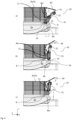
- Fig.7 shows partial views of an ELBO with a third embodiment of a slag door arrangement in six sectional views along a line corresponding to the line AA of Fig. 3a ), which show in a) to f) different positions in a movement sequence of the slag door 1 1 for cleaning the slag tunnel 8.
- the third embodiment corresponds to the first embodiment except for the differences described below and the description of the corresponding features will not be repeated.
- the cover 40 is also plate-like, but not movable, but firmly attached to the upper edge of the furnace vessel 2. Its position is not changed, unlike in the first embodiment.
- the pivoting range is different from the first and second embodiments.
- the variant is implemented in which the second pivoting angle ⁇ lies relative to the vertical plane E through the horizontal pivot axis H in the direction away from the furnace vessel 2, so that the amount of the pivoting angle range ⁇ is equal to the sum of the amounts of the first pivoting angle ⁇ and the second pivoting angle ⁇ .
- Fig.7 shows a two-stage cleaning.
- the lifting position of the slag door lifter 30 is changed from the Fig. 7 a) shown position in the direction of the first lower minimum lifting position U until either a predetermined distance is reached or the predetermined first limit value of the measured force is reached ( Fig. 7 b) ).
- the lifting position can be changed again towards the second upper maximum lifting position O and, for example, a visual inspection of the slag tunnel can be carried out by camera or by eye.
- the angular range ⁇ between the first pivot angle ⁇ and the second pivot angle ⁇ is between 25° and 60°, preferably 25° or 30° or 35° or 40° or 41° or 45° or 50° or 55° or 60°.
- the first pivot angle ⁇ has an amount in the range of 25° to 45°, preferably 25° to 35°, preferably 26° to 35° relative to the plane E through the horizontal pivot axis H and is preferably 25° or 26° or 35°.
- the second pivot angle ⁇ has an amount in the range of 0° to 25°, preferably 0° to 20°, preferably 0° to 15° relative to the plane E through the horizontal pivot axis H and is preferably 0° or 5° or 10° or 15°.
- the slag door arrangement is adapted for use in metallurgical furnaces, especially ELBOs with tapping masses of 50 to 200 t.
Landscapes
- Engineering & Computer Science (AREA)
- Mechanical Engineering (AREA)
- General Engineering & Computer Science (AREA)
- Vertical, Hearth, Or Arc Furnaces (AREA)
Claims (15)
- Dispositif de porte de scories (10) pour un four métallurgique (1), qui comprend une cuve de four (2) avec un tunnel de scories (8) ayant une section d'ouverture rectangulaire, qui est prévue latéralement dans la cuve de four (2), comprenantune porte de scories (11), de préférence de type plaque,un pivot de porte de scories (20), qui peut pivoter autour d'un axe de pivotement horizontal (H), etun élévateur de porte de scories (30), sur lequel la porte de scories (11) est montée et qui est adapté pour déplacer la porte de scories (11) entre une première position de levage minimale inférieure (U) et une deuxième position de levage maximale supérieure (O) perpendiculairement à l'axe de pivotement horizontal (H),caractérisé en ce quela porte de scories (11) a une largeur qui correspond à la largeur de la section d'ouverture rectangulaire du tunnel de scories (8) avec un jeu (s), qui permet un mouvement de la porte de scories (11) dans le tunnel de scories (8),le pivot de porte de scories (20) est pivotable pour pivoter autour de l'axe de pivotement horizontal (H) sur une plage d'angles de pivotement (σ) entre un premier angle de pivotement (α), qui est situé par rapport à un plan vertical (E) à travers l'axe de pivotement horizontal (H) en direction de la cuve de four, et un deuxième angle de pivotement (β), qui est situé dans le plan vertical (E) ou, par rapport au plan vertical (E), à travers l'axe de pivotement horizontal (H) en direction opposée à celle de la cuve de four, etl'élévateur de porte de scories (30) est monté sur le pivot de porte de scories (20),de sorte qu'un mouvement de pivotement de la porte de scories autour de l'axe de pivotement horizontal et un mouvement de levage de la porte de scories dans la direction perpendiculaire à l'axe de pivotement horizontal sont indépendants l'un de l'autre.
- Dispositif de porte de scories selon la revendication 1, dans lequel
un panneau refroidi par eau (12) est fixé à la porte de scories de type plaque (11) sur le côté faisant face à l'intérieur de la cuve de four (2). - Dispositif de porte de scories selon la revendication 1 ou 2, dans lequel
un poussoir à scories (14) est fixé à la porte de scories de type plaque (11) sur son côté inférieur opposé à l'axe de pivotement horizontal (H). - Dispositif de porte de scories selon l'une quelconque des revendications précédentes, dans lequel
le pivot de porte de scories (20) comprend une bielle (21), qui est adaptée pour être montée latéralement des deux côtés du tunnel de scories (8) sur la cuve de four (2) de telle sorte qu'elle peut pivoter autour de l'axe de pivotement horizontal (H), et un cylindre hydraulique (22), qui est relié à une extrémité à la bielle (21) et à son autre extrémité est adapté pour être monté sur la cuve de four (2). - Dispositif de porte de scories selon l'une quelconque des revendications précédentes, dans lequel
l'élévateur de porte de scories (30) comprend un cylindre de levage hydraulique (31) qui est relié à une extrémité à la porte de scories (11) et à son autre extrémité au pivot de porte de scories (20), et un guide linéaire (32), dans lequel la porte de scories (11) est montée de manière coulissante et qui est monté sur le pivot de porte de scories (20). - Dispositif de porte de scories selon l'une quelconque des revendications précédentes, dans lequel
un couvercle de protection (40) est prévu dans la direction verticale au-dessus de la porte de scories (11), du pivot de porte de scories (20) et de l'élévateur de porte de scories (30), dont les dimensions extérieures dans une vue de dessus verticale couvrent la porte de scories (11), le pivot de porte de scories (20) et l'élévateur de porte de scories (30) dans chaque position de pivotement et de levage de ceux-ci. - Dispositif de porte de scories selon l'une quelconque des revendications précédentes, dans lequella plage d'angles (σ) entre le premier angle de pivotement (α) et le deuxième angle de pivotement (β) est comprise entre 25° et 60°, de préférence 25° ou 30° ou 35° ou 40° ou 41° ou 45° ou 50° ou 55° ou 60°,le premier angle de pivotement (α) a une valeur dans la plage de 25° à 45°, de préférence de 25° à 35°, de préférence de 26° à 35° par rapport au plan (E) à travers l'axe de pivotement horizontal (H) et est de préférence de 25° ou 26° ou 35°, etle deuxième angle de pivotement (β) a une valeur dans la plage de 0° à 25°, de préférence de 0° à 20°, de préférence de 0° à 15° par rapport au plan (E) à travers l'axe de pivotement horizontal (H) et est de préférence de 0° ou 5° ou 10° ou 15°.
- Dispositif de porte de scories selon l'une des revendications précédentes, qui comprendun dispositif de commande (50), qui est connecté au pivot de porte de scories (20) et à l'élévateur de porte de scories (30) et qui est adapté pour entrer et stocker des paramètres pour contrôler les positions de pivotement et de levage de ceux-ci, etest adapté pour mesurer la force dépensée lors du déplacement de la porte de scories, soit directement par des capteurs de mesure, soit indirectement par l'évaluation des paramètres des actionneurs, et pour arrêter, lorsqu'une première valeur limite prédéterminée de la force mesurée est atteinte, le mouvement de la porte de scories (11) en direction de la première position de levage minimale inférieure (U) et, si une deuxième valeur limite prédéterminée de la force mesurée est atteinte lors du déplacement de la porte de scories (11), pour interrompre le mouvement et pour émettre un message correspondant.
- Four métallurgique (1), en particulier four à arc électrique, avecune cuve de four (2), qui a une paroi latérale (2s) et un tunnel de scories (8), qui est prévu latéralement dans la paroi latérale (2s) de la cuve de four (2) avec une section d'ouverture rectangulaire et qui a des parois latérales (8s), un bord extérieur supérieur (8or) et un fond (8b),un dispositif de basculement de four avec un berceau (3), sur lequel la cuve de four (2) repose, pour basculer la cuve de four par rapport à l'horizontale d'une fondation (7) sur laquelle le four métallurgique est placé, etun dispositif de porte de scories selon l'une des revendications 1 à 8,dans lequel le dispositif de porte de scories est monté sur la cuve de four (2) de telle manièreque, dans une position de basculement horizontale de la cuve de four (2), le plan (E) à travers l'axe de pivotement horizontal (H) est perpendiculaire à l'horizontale,que l'axe de pivotement horizontal (H) est situé à l'extérieur de la cuve de four (2), etque la porte de scories (11) dans une position pivotée du pivot de porte de scories (20) autour de l'axe de pivotement horizontal (H) par un troisième angle de pivotement (α'), qui correspond à l'angle de pivotement initial (α) moins 0 à 5°, et dans une position de l'élévateur de porte de scories (30) dans laquelle la porte de scories (11) est déplacée en direction de la première position de levage minimale inférieure (U) jusqu'à ce qu'elle touche le fond (8b) du tunnel de scories (8), fait saillie en biais de l'extérieur vers le haut dans le tunnel de scories et est opposée aux parois latérales (8s) avec le jeu (s).
- Four à arc électrique selon la revendication 9, dans lequelle fond (8b) du tunnel de scories (8), dans une vue de dessus, est prolongé latéralement au-delà de la paroi latérale (2s) de la cuve de four (2) jusqu'à un bord de fond (8r),la porte de scories (11) dans une position pivotée du pivot de porte de scories (20) autour de l'axe de pivotement horizontal (H) par un quatrième angle de pivotement (β'), qui correspond à l'angle de pivotement secondaire (β) moins 0 à 5°, et dans une position de l'élévateur de porte de scories (30) dans laquelle la porte de scories (11) est déplacée en direction de la première position de levage minimale inférieure (U) jusqu'à ce qu'elle touche le fond (8b) du tunnel de scories (8), touche le fond au bord de fond (8r).
- Four à arc électrique selon la revendication 9 ou 10, dans lequelle dispositif de porte de scories (10) comprend le dispositif de commande (50) selon la revendication 8, qui est adapté pour contrôler les positions de pivotement du pivot de porte de scories (20) et les positions de levage de l'élévateur de porte de scories (30) de telle manière que, pour nettoyer le tunnel de scories (8), la porte de scories (11) effectue un mouvement de nettoyage à partir d'une position dans le tunnel de scories en direction de l'extérieur du four hors du tunnel de scories,soit parallèlement au sol à une distance choisissable du sol ou en contact avec le sol (8b) du tunnel de scories (8),soit dans un mouvement sur un segment de cercle avec une distance minimale lors de l'approche la plus proche, cette distance minimale pouvant également être réglée sur zéro.
- Procédure pour nettoyer une ouverture de scories d'un four métallurgique (1), en particulier d'un four à arc électrique, qui a une cuve de four (2), qui a une paroi latérale (2s), un tunnel de scories (8), qui est prévu latéralement dans la paroi latérale (2s) de la cuve de four (2) avec une section d'ouverture rectangulaire et qui a des parois latérales (8s), un bord extérieur supérieur (8or) et un fond (8b), et un agencement de porte de scories selon l'une des revendications 1 à 8, dont l'axe de pivotement horizontal (H) est situé à l'extérieur de la cuve de four (2), avec les étapes :a) déplacer le pivot de porte de scories (20), après une scorification, où la porte de scories (11) est déplacée par l'élévateur de porte de scories (30) dans la deuxième position de levage maximale supérieure (O) ou près de celle-ci, dans une position pivotée autour de l'axe de pivotement horizontal (H) par un troisième angle de pivotement (α'), qui correspond à l'angle de pivotement initial (α) moins 0 à 5° ;b) déplacer la porte de scories (11) par l'élévateur de porte de scories (30) en direction de la première position de levage minimale inférieure (U) jusqu'à une distance prédéterminée du fond (8b) du tunnel de scories (8), de sorte que la porte de scories fait saillie en biais de l'extérieur vers le haut dans le tunnel de scories et est opposée à ses parois latérales (8s) avec le jeu (s) ;c) déplacer le pivot de porte de scories (20) autour de l'axe de pivotement horizontal (H) en direction du deuxième angle de pivotement (β) jusqu'à un quatrième angle de pivotement (β'), qui correspond au deuxième angle de pivotement (β) moins 0 à 5°, soit en déplaçant simultanément la porte de scories (11) par l'élévateur de porte de scories (30) pour maintenir au moins la distance prédéterminée du fond (8b) du tunnel de scories (8), de sorte que la porte de scories est déplacée au moins à la distance prédéterminée parallèlement à et le long du fond (8b), soit dans un mouvement sur un segment de cercle avec une distance minimale à l'approche la plus grande ; etd) déplacer le pivot de porte de scories (20) autour de l'axe de pivotement horizontal (H) en direction du premier angle de pivotement (α) dans une position pivotée par le troisième angle de pivotement (α'), qui correspond à l'angle de pivotement initial (α) moins 0 à 5°, avec la porte de scories (11) déplacée en direction de la deuxième position de levage maximale supérieure (O), de sorte que la porte de scories est alors déplacée à une distance du fond (8b), qui est supérieure à la distance prédéterminée ou à la distance minimale ; ete) déplacer la porte de scories (11) par l'élévateur de porte de scories (30) en direction de la première position de levage minimale inférieure (U) jusqu'à ce qu'elle touche le fond (8b) du tunnel de scories (8), de sorte que la porte de scories fait saillie en biais de l'extérieur vers le haut dans le tunnel de scories et est opposée à ses parois latérales (8s) avec le jeu (s).
- Procédure selon la revendication 12, dans laquelle
les étapes a) à c) sont répétées avant l'exécution des étapes d) et e), dans le cas du mouvement parallèle au sol avec une distance prédéterminée réduite par rapport à la précédente distance prédéterminée du fond (8b) du tunnel de scories (8) et dans le cas du mouvement sur un segment de cercle avec une distance minimale réduite par rapport à la distance minimale précédente à l'approche la plus grande. - Procédure selon la revendication 12 ou 13, dans laquelle
la distance prédéterminée ou la distance minimale ou la distance prédéterminée réduite ou la distance minimale réduite est fixée à zéro. - Procédure selon l'une des revendications 12 à 14, dans laquellela force appliquée pour déplacer la porte de scories dans les étapes a) à e) est mesurée, età l'étape b), lorsqu'un premier seuil prédéterminé de la force mesurée est atteint, le mouvement de la porte de scories (11) en direction de la première position de levage minimale inférieure (U) est arrêté et la distance du fond (8b) du tunnel de scories (8) est utilisée comme la distance prédéterminée ou la distance minimale pour l'étape c) suivante, etaux étapes a) à e), lorsqu'un deuxième seuil prédéterminé individuellement pour chacune des étapes de la force mesurée est atteint, l'exécution de la procédure est interrompue.
Priority Applications (2)
| Application Number | Priority Date | Filing Date | Title |
|---|---|---|---|
| EP21206173.3A EP4177555B1 (fr) | 2021-11-03 | 2021-11-03 | Agencement de porte à scories et procédé de nettoyage |
| US18/051,605 US20230133535A1 (en) | 2021-11-03 | 2022-11-01 | Slag door arrangement and cleaning method |
Applications Claiming Priority (1)
| Application Number | Priority Date | Filing Date | Title |
|---|---|---|---|
| EP21206173.3A EP4177555B1 (fr) | 2021-11-03 | 2021-11-03 | Agencement de porte à scories et procédé de nettoyage |
Publications (3)
| Publication Number | Publication Date |
|---|---|
| EP4177555A1 EP4177555A1 (fr) | 2023-05-10 |
| EP4177555C0 EP4177555C0 (fr) | 2024-08-21 |
| EP4177555B1 true EP4177555B1 (fr) | 2024-08-21 |
Family
ID=78516605
Family Applications (1)
| Application Number | Title | Priority Date | Filing Date |
|---|---|---|---|
| EP21206173.3A Active EP4177555B1 (fr) | 2021-11-03 | 2021-11-03 | Agencement de porte à scories et procédé de nettoyage |
Country Status (2)
| Country | Link |
|---|---|
| US (1) | US20230133535A1 (fr) |
| EP (1) | EP4177555B1 (fr) |
Families Citing this family (2)
| Publication number | Priority date | Publication date | Assignee | Title |
|---|---|---|---|---|
| US12152283B2 (en) | 2022-02-18 | 2024-11-26 | Badische Stahl-Engineering Gmbh | Device and method for filling a tap hole of an electric arc furnace with refractory filling material |
| EP4644812A1 (fr) * | 2024-04-30 | 2025-11-05 | Primetals Technologies Austria GmbH | Installation de four à arc électrique avec alimentation en métal liquide à travers une ouverture refermable |
Family Cites Families (9)
| Publication number | Priority date | Publication date | Assignee | Title |
|---|---|---|---|---|
| US4679773A (en) | 1985-09-30 | 1987-07-14 | Wunsche Edgar R | Horizontal tapping furnace and method of operation |
| DK0385434T3 (da) | 1989-03-02 | 1993-06-07 | Arcmet Tech Gmbh | Smelteaggregat med skaktformet chargematerialeforvarmer |
| IT1315701B1 (it) * | 2000-05-31 | 2003-03-18 | Borli Engineering Spa | Porta automatica per forno di mantenimento di metallo fuso |
| CN101501435A (zh) | 2006-06-20 | 2009-08-05 | 恩普科(加拿大)有限公司 | 用于冶金炉的炉渣门的密封装置 |
| IT1393096B1 (it) | 2009-02-19 | 2012-04-11 | Sms Concast Italia Srl | Porta di scorifica in forno metallurgico ad arco costituito da un pannello mobile inferiore estrattore della scoria e da un pannello mobile superiore apribile per effettuare rilievi e interventi sul metallo fuso, e relativo apparato di comando |
| US8206642B2 (en) | 2010-03-16 | 2012-06-26 | Process Technology International | Pivoting slag door |
| EP2489971B1 (fr) | 2011-02-16 | 2017-07-12 | SMS group S.p.A. | Porte de laitier de four et four correspondant |
| ITMI20120532A1 (it) * | 2012-04-02 | 2013-10-03 | Tenova Spa | Apparato di chiusura della porta di scorifica e di pulizia della porta e del canale di scorifica di un forno metallurgico e relativo metodo |
| ES2568519B1 (es) * | 2015-08-12 | 2017-02-08 | Sarralle Equipos Siderúrgicos, S.L. | Puerta de desescoriado para horno y horno asociado |
-
2021
- 2021-11-03 EP EP21206173.3A patent/EP4177555B1/fr active Active
-
2022
- 2022-11-01 US US18/051,605 patent/US20230133535A1/en active Pending
Also Published As
| Publication number | Publication date |
|---|---|
| EP4177555A1 (fr) | 2023-05-10 |
| EP4177555C0 (fr) | 2024-08-21 |
| US20230133535A1 (en) | 2023-05-04 |
Similar Documents
| Publication | Publication Date | Title |
|---|---|---|
| DE69413096T2 (de) | Verfahren und Vorrichtung zum Schmelzen von Glas | |
| EP2059758B9 (fr) | Four de fusion et en particulier four à arc lumineux | |
| WO1990010086A2 (fr) | Agregat de fusion a puits de prechauffage des matieres chargees | |
| EP1419355B1 (fr) | Four metallurgique et panier a matiere pour ledit four | |
| EP3892947A1 (fr) | Dispositif d'entretien du trou de coulée d'un four à arc électrique | |
| EP0958481B1 (fr) | Groupe de fusion comportant un four a arc | |
| EP4177555A1 (fr) | Agencement de porte à scories et procédé de nettoyage | |
| EP2281166B1 (fr) | Installation de four | |
| DE4208061C2 (de) | Induktionsofen für das Schmelzen und Abgießen von Stoffen in nicht-reaktiver Atmosphäre | |
| WO1993010413A1 (fr) | Unite de fusion avec berceau de four | |
| EP1060275B1 (fr) | Dispositif pour prechauffer une charge d'alimentation, comportant des sections de parois de puits remplacables | |
| DE102008012280A1 (de) | Lichtbogenofen | |
| EP2606304B1 (fr) | Dispositif de levage et de pivotement pour un couvercle d'un four ainsi qu'installation de four et procédé pour charger et pour entretenir une telle installation de four | |
| WO1994014983A1 (fr) | Basculeur de four a arc a courant continu et procede de vidage du four | |
| DE3412077C2 (fr) | ||
| EP2619335B1 (fr) | Dispositif de préchauffage pour ferraille d'acier et récipient de fusion métallurgique ainsi équipé | |
| EP0216187B1 (fr) | Conteneur de four métallurgique, en particulier d'un four à arc | |
| WO2011009579A1 (fr) | Dispositif détanchéification et de remplissage dun four métallurgique, four métallurgique et procédé de percée dun four métallurgique | |
| EP3473733B1 (fr) | Récipient intermediaire pour la séparation de laitier | |
| DE112005002997B4 (de) | Behälter | |
| DE102009033934B3 (de) | Abdicht- und Verfüllvorrichtung für einen metallurgischen Ofen, metallurgischer Ofen und Verfahren zum Abstechen eines metallurgischen Ofens | |
| DE202013103865U1 (de) | Entfernvorrichtung für Schlacke | |
| DD292517A5 (de) | Einschmelzaggregat mit schachtfoermigem chargiergutvorwaermer | |
| DE2518168C2 (de) | Elektro-Reduktionsofen | |
| DE102010041694A1 (de) | Hub- und Schwenkvorrichtung für einen Deckel eines Ofens sowie Ofenanlage und Verfahren zum Chargieren und zur Wartung einer solchen Ofenanlage |
Legal Events
| Date | Code | Title | Description |
|---|---|---|---|
| PUAI | Public reference made under article 153(3) epc to a published international application that has entered the european phase |
Free format text: ORIGINAL CODE: 0009012 |
|
| STAA | Information on the status of an ep patent application or granted ep patent |
Free format text: STATUS: THE APPLICATION HAS BEEN PUBLISHED |
|
| STAA | Information on the status of an ep patent application or granted ep patent |
Free format text: STATUS: REQUEST FOR EXAMINATION WAS MADE |
|
| AK | Designated contracting states |
Kind code of ref document: A1 Designated state(s): AL AT BE BG CH CY CZ DE DK EE ES FI FR GB GR HR HU IE IS IT LI LT LU LV MC MK MT NL NO PL PT RO RS SE SI SK SM TR |
|
| 17P | Request for examination filed |
Effective date: 20230503 |
|
| RBV | Designated contracting states (corrected) |
Designated state(s): AL AT BE BG CH CY CZ DE DK EE ES FI FR GB GR HR HU IE IS IT LI LT LU LV MC MK MT NL NO PL PT RO RS SE SI SK SM TR |
|
| STAA | Information on the status of an ep patent application or granted ep patent |
Free format text: STATUS: EXAMINATION IS IN PROGRESS |
|
| 17Q | First examination report despatched |
Effective date: 20230912 |
|
| GRAP | Despatch of communication of intention to grant a patent |
Free format text: ORIGINAL CODE: EPIDOSNIGR1 |
|
| STAA | Information on the status of an ep patent application or granted ep patent |
Free format text: STATUS: GRANT OF PATENT IS INTENDED |
|
| INTG | Intention to grant announced |
Effective date: 20240318 |
|
| GRAS | Grant fee paid |
Free format text: ORIGINAL CODE: EPIDOSNIGR3 |
|
| GRAA | (expected) grant |
Free format text: ORIGINAL CODE: 0009210 |
|
| STAA | Information on the status of an ep patent application or granted ep patent |
Free format text: STATUS: THE PATENT HAS BEEN GRANTED |
|
| AK | Designated contracting states |
Kind code of ref document: B1 Designated state(s): AL AT BE BG CH CY CZ DE DK EE ES FI FR GB GR HR HU IE IS IT LI LT LU LV MC MK MT NL NO PL PT RO RS SE SI SK SM TR |
|
| REG | Reference to a national code |
Ref country code: GB Ref legal event code: FG4D Free format text: NOT ENGLISH |
|
| REG | Reference to a national code |
Ref country code: CH Ref legal event code: EP |
|
| REG | Reference to a national code |
Ref country code: DE Ref legal event code: R096 Ref document number: 502021004844 Country of ref document: DE |
|
| REG | Reference to a national code |
Ref country code: IE Ref legal event code: FG4D Free format text: LANGUAGE OF EP DOCUMENT: GERMAN |
|
| U01 | Request for unitary effect filed |
Effective date: 20240821 |
|
| U07 | Unitary effect registered |
Designated state(s): AT BE BG DE DK EE FI FR IT LT LU LV MT NL PT RO SE SI Effective date: 20240902 |
|
| U20 | Renewal fee for the european patent with unitary effect paid |
Year of fee payment: 4 Effective date: 20241106 |
|
| PG25 | Lapsed in a contracting state [announced via postgrant information from national office to epo] |
Ref country code: NO Free format text: LAPSE BECAUSE OF FAILURE TO SUBMIT A TRANSLATION OF THE DESCRIPTION OR TO PAY THE FEE WITHIN THE PRESCRIBED TIME-LIMIT Effective date: 20241121 |
|
| PG25 | Lapsed in a contracting state [announced via postgrant information from national office to epo] |
Ref country code: PL Free format text: LAPSE BECAUSE OF FAILURE TO SUBMIT A TRANSLATION OF THE DESCRIPTION OR TO PAY THE FEE WITHIN THE PRESCRIBED TIME-LIMIT Effective date: 20240821 Ref country code: GR Free format text: LAPSE BECAUSE OF FAILURE TO SUBMIT A TRANSLATION OF THE DESCRIPTION OR TO PAY THE FEE WITHIN THE PRESCRIBED TIME-LIMIT Effective date: 20241122 |
|
| PG25 | Lapsed in a contracting state [announced via postgrant information from national office to epo] |
Ref country code: IS Free format text: LAPSE BECAUSE OF FAILURE TO SUBMIT A TRANSLATION OF THE DESCRIPTION OR TO PAY THE FEE WITHIN THE PRESCRIBED TIME-LIMIT Effective date: 20241221 |
|
| PG25 | Lapsed in a contracting state [announced via postgrant information from national office to epo] |
Ref country code: HR Free format text: LAPSE BECAUSE OF FAILURE TO SUBMIT A TRANSLATION OF THE DESCRIPTION OR TO PAY THE FEE WITHIN THE PRESCRIBED TIME-LIMIT Effective date: 20240821 |
|
| PG25 | Lapsed in a contracting state [announced via postgrant information from national office to epo] |
Ref country code: RS Free format text: LAPSE BECAUSE OF FAILURE TO SUBMIT A TRANSLATION OF THE DESCRIPTION OR TO PAY THE FEE WITHIN THE PRESCRIBED TIME-LIMIT Effective date: 20241121 Ref country code: ES Free format text: LAPSE BECAUSE OF FAILURE TO SUBMIT A TRANSLATION OF THE DESCRIPTION OR TO PAY THE FEE WITHIN THE PRESCRIBED TIME-LIMIT Effective date: 20240821 |
|
| PG25 | Lapsed in a contracting state [announced via postgrant information from national office to epo] |
Ref country code: RS Free format text: LAPSE BECAUSE OF FAILURE TO SUBMIT A TRANSLATION OF THE DESCRIPTION OR TO PAY THE FEE WITHIN THE PRESCRIBED TIME-LIMIT Effective date: 20241121 Ref country code: PL Free format text: LAPSE BECAUSE OF FAILURE TO SUBMIT A TRANSLATION OF THE DESCRIPTION OR TO PAY THE FEE WITHIN THE PRESCRIBED TIME-LIMIT Effective date: 20240821 Ref country code: NO Free format text: LAPSE BECAUSE OF FAILURE TO SUBMIT A TRANSLATION OF THE DESCRIPTION OR TO PAY THE FEE WITHIN THE PRESCRIBED TIME-LIMIT Effective date: 20241121 Ref country code: IS Free format text: LAPSE BECAUSE OF FAILURE TO SUBMIT A TRANSLATION OF THE DESCRIPTION OR TO PAY THE FEE WITHIN THE PRESCRIBED TIME-LIMIT Effective date: 20241221 Ref country code: HR Free format text: LAPSE BECAUSE OF FAILURE TO SUBMIT A TRANSLATION OF THE DESCRIPTION OR TO PAY THE FEE WITHIN THE PRESCRIBED TIME-LIMIT Effective date: 20240821 Ref country code: GR Free format text: LAPSE BECAUSE OF FAILURE TO SUBMIT A TRANSLATION OF THE DESCRIPTION OR TO PAY THE FEE WITHIN THE PRESCRIBED TIME-LIMIT Effective date: 20241122 Ref country code: ES Free format text: LAPSE BECAUSE OF FAILURE TO SUBMIT A TRANSLATION OF THE DESCRIPTION OR TO PAY THE FEE WITHIN THE PRESCRIBED TIME-LIMIT Effective date: 20240821 |
|
| PG25 | Lapsed in a contracting state [announced via postgrant information from national office to epo] |
Ref country code: SM Free format text: LAPSE BECAUSE OF FAILURE TO SUBMIT A TRANSLATION OF THE DESCRIPTION OR TO PAY THE FEE WITHIN THE PRESCRIBED TIME-LIMIT Effective date: 20240821 |
|
| PG25 | Lapsed in a contracting state [announced via postgrant information from national office to epo] |
Ref country code: CZ Free format text: LAPSE BECAUSE OF FAILURE TO SUBMIT A TRANSLATION OF THE DESCRIPTION OR TO PAY THE FEE WITHIN THE PRESCRIBED TIME-LIMIT Effective date: 20240821 |
|
| PG25 | Lapsed in a contracting state [announced via postgrant information from national office to epo] |
Ref country code: SK Free format text: LAPSE BECAUSE OF FAILURE TO SUBMIT A TRANSLATION OF THE DESCRIPTION OR TO PAY THE FEE WITHIN THE PRESCRIBED TIME-LIMIT Effective date: 20240821 |
|
| PLBE | No opposition filed within time limit |
Free format text: ORIGINAL CODE: 0009261 |
|
| STAA | Information on the status of an ep patent application or granted ep patent |
Free format text: STATUS: NO OPPOSITION FILED WITHIN TIME LIMIT |
|
| PG25 | Lapsed in a contracting state [announced via postgrant information from national office to epo] |
Ref country code: MC Free format text: LAPSE BECAUSE OF FAILURE TO SUBMIT A TRANSLATION OF THE DESCRIPTION OR TO PAY THE FEE WITHIN THE PRESCRIBED TIME-LIMIT Effective date: 20240821 |
|
| 26N | No opposition filed |
Effective date: 20250522 |
|
| PG25 | Lapsed in a contracting state [announced via postgrant information from national office to epo] |
Ref country code: IE Free format text: LAPSE BECAUSE OF NON-PAYMENT OF DUE FEES Effective date: 20241103 |
|
| REG | Reference to a national code |
Ref country code: CH Ref legal event code: U11 Free format text: ST27 STATUS EVENT CODE: U-0-0-U10-U11 (AS PROVIDED BY THE NATIONAL OFFICE) Effective date: 20251201 |
|
| U20 | Renewal fee for the european patent with unitary effect paid |
Year of fee payment: 5 Effective date: 20251118 |
|
| PGFP | Annual fee paid to national office [announced via postgrant information from national office to epo] |
Ref country code: TR Payment date: 20251030 Year of fee payment: 5 |
|
| PGFP | Annual fee paid to national office [announced via postgrant information from national office to epo] |
Ref country code: CH Payment date: 20251201 Year of fee payment: 5 |
|
| PG25 | Lapsed in a contracting state [announced via postgrant information from national office to epo] |
Ref country code: HU Free format text: LAPSE BECAUSE OF FAILURE TO SUBMIT A TRANSLATION OF THE DESCRIPTION OR TO PAY THE FEE WITHIN THE PRESCRIBED TIME-LIMIT; INVALID AB INITIO Effective date: 20211103 |
|
| PG25 | Lapsed in a contracting state [announced via postgrant information from national office to epo] |
Ref country code: CY Free format text: LAPSE BECAUSE OF FAILURE TO SUBMIT A TRANSLATION OF THE DESCRIPTION OR TO PAY THE FEE WITHIN THE PRESCRIBED TIME-LIMIT; INVALID AB INITIO Effective date: 20211103 |