EP4177561B1 - Échangeur de chaleur, pompe à chaleur et procédé de sécurisation forestière d'un échangeur de chaleur - Google Patents
Échangeur de chaleur, pompe à chaleur et procédé de sécurisation forestière d'un échangeur de chaleur Download PDFInfo
- Publication number
- EP4177561B1 EP4177561B1 EP22202473.9A EP22202473A EP4177561B1 EP 4177561 B1 EP4177561 B1 EP 4177561B1 EP 22202473 A EP22202473 A EP 22202473A EP 4177561 B1 EP4177561 B1 EP 4177561B1
- Authority
- EP
- European Patent Office
- Prior art keywords
- heat exchanger
- heat
- discharge
- condensate
- heat pump
- Prior art date
- Legal status (The legal status is an assumption and is not a legal conclusion. Google has not performed a legal analysis and makes no representation as to the accuracy of the status listed.)
- Active
Links
Images

Classifications
-
- F—MECHANICAL ENGINEERING; LIGHTING; HEATING; WEAPONS; BLASTING
- F28—HEAT EXCHANGE IN GENERAL
- F28D—HEAT-EXCHANGE APPARATUS, NOT PROVIDED FOR IN ANOTHER SUBCLASS, IN WHICH THE HEAT-EXCHANGE MEDIA DO NOT COME INTO DIRECT CONTACT
- F28D1/00—Heat-exchange apparatus having stationary conduit assemblies for one heat-exchange medium only, the media being in contact with different sides of the conduit wall, in which the other heat-exchange medium is a large body of fluid, e.g. domestic or motor car radiators
- F28D1/02—Heat-exchange apparatus having stationary conduit assemblies for one heat-exchange medium only, the media being in contact with different sides of the conduit wall, in which the other heat-exchange medium is a large body of fluid, e.g. domestic or motor car radiators with heat-exchange conduits immersed in the body of fluid
- F28D1/04—Heat-exchange apparatus having stationary conduit assemblies for one heat-exchange medium only, the media being in contact with different sides of the conduit wall, in which the other heat-exchange medium is a large body of fluid, e.g. domestic or motor car radiators with heat-exchange conduits immersed in the body of fluid with tubular conduits
- F28D1/047—Heat-exchange apparatus having stationary conduit assemblies for one heat-exchange medium only, the media being in contact with different sides of the conduit wall, in which the other heat-exchange medium is a large body of fluid, e.g. domestic or motor car radiators with heat-exchange conduits immersed in the body of fluid with tubular conduits the conduits being bent, e.g. in a serpentine or zig-zag
- F28D1/0477—Heat-exchange apparatus having stationary conduit assemblies for one heat-exchange medium only, the media being in contact with different sides of the conduit wall, in which the other heat-exchange medium is a large body of fluid, e.g. domestic or motor car radiators with heat-exchange conduits immersed in the body of fluid with tubular conduits the conduits being bent, e.g. in a serpentine or zig-zag the conduits being bent in a serpentine or zig-zag
-
- F—MECHANICAL ENGINEERING; LIGHTING; HEATING; WEAPONS; BLASTING
- F24—HEATING; RANGES; VENTILATING
- F24F—AIR-CONDITIONING; AIR-HUMIDIFICATION; VENTILATION; USE OF AIR CURRENTS FOR SCREENING
- F24F1/00—Room units for air-conditioning, e.g. separate or self-contained units or units receiving primary air from a central station
- F24F1/06—Separate outdoor units, e.g. outdoor unit to be linked to a separate room comprising a compressor and a heat exchanger
- F24F1/14—Heat exchangers specially adapted for separate outdoor units
-
- F—MECHANICAL ENGINEERING; LIGHTING; HEATING; WEAPONS; BLASTING
- F24—HEATING; RANGES; VENTILATING
- F24F—AIR-CONDITIONING; AIR-HUMIDIFICATION; VENTILATION; USE OF AIR CURRENTS FOR SCREENING
- F24F13/00—Details common to, or for air-conditioning, air-humidification, ventilation or use of air currents for screening
- F24F13/22—Means for preventing condensation or evacuating condensate
- F24F13/222—Means for preventing condensation or evacuating condensate for evacuating condensate
-
- F—MECHANICAL ENGINEERING; LIGHTING; HEATING; WEAPONS; BLASTING
- F25—REFRIGERATION OR COOLING; COMBINED HEATING AND REFRIGERATION SYSTEMS; HEAT PUMP SYSTEMS; MANUFACTURE OR STORAGE OF ICE; LIQUEFACTION SOLIDIFICATION OF GASES
- F25B—REFRIGERATION MACHINES, PLANTS OR SYSTEMS; COMBINED HEATING AND REFRIGERATION SYSTEMS; HEAT PUMP SYSTEMS
- F25B39/00—Evaporators; Condensers
- F25B39/02—Evaporators
-
- F—MECHANICAL ENGINEERING; LIGHTING; HEATING; WEAPONS; BLASTING
- F25—REFRIGERATION OR COOLING; COMBINED HEATING AND REFRIGERATION SYSTEMS; HEAT PUMP SYSTEMS; MANUFACTURE OR STORAGE OF ICE; LIQUEFACTION SOLIDIFICATION OF GASES
- F25B—REFRIGERATION MACHINES, PLANTS OR SYSTEMS; COMBINED HEATING AND REFRIGERATION SYSTEMS; HEAT PUMP SYSTEMS
- F25B47/00—Arrangements for preventing or removing deposits or corrosion, not provided for in another subclass
- F25B47/006—Arrangements for preventing or removing deposits or corrosion, not provided for in another subclass for preventing frost
-
- F—MECHANICAL ENGINEERING; LIGHTING; HEATING; WEAPONS; BLASTING
- F25—REFRIGERATION OR COOLING; COMBINED HEATING AND REFRIGERATION SYSTEMS; HEAT PUMP SYSTEMS; MANUFACTURE OR STORAGE OF ICE; LIQUEFACTION SOLIDIFICATION OF GASES
- F25D—REFRIGERATORS; COLD ROOMS; ICE-BOXES; COOLING OR FREEZING APPARATUS NOT OTHERWISE PROVIDED FOR
- F25D21/00—Defrosting; Preventing frosting; Removing condensed or defrost water
- F25D21/14—Collecting or removing condensed and defrost water; Drip trays
-
- F—MECHANICAL ENGINEERING; LIGHTING; HEATING; WEAPONS; BLASTING
- F28—HEAT EXCHANGE IN GENERAL
- F28F—DETAILS OF HEAT-EXCHANGE AND HEAT-TRANSFER APPARATUS, OF GENERAL APPLICATION
- F28F1/00—Tubular elements; Assemblies of tubular elements
- F28F1/10—Tubular elements and assemblies thereof with means for increasing heat-transfer area, e.g. with fins, with projections, with recesses
- F28F1/12—Tubular elements and assemblies thereof with means for increasing heat-transfer area, e.g. with fins, with projections, with recesses the means being only outside the tubular element
- F28F1/24—Tubular elements and assemblies thereof with means for increasing heat-transfer area, e.g. with fins, with projections, with recesses the means being only outside the tubular element and extending transversely
- F28F1/32—Tubular elements and assemblies thereof with means for increasing heat-transfer area, e.g. with fins, with projections, with recesses the means being only outside the tubular element and extending transversely the means having portions engaging further tubular elements
-
- F—MECHANICAL ENGINEERING; LIGHTING; HEATING; WEAPONS; BLASTING
- F28—HEAT EXCHANGE IN GENERAL
- F28F—DETAILS OF HEAT-EXCHANGE AND HEAT-TRANSFER APPARATUS, OF GENERAL APPLICATION
- F28F17/00—Removing ice or water from heat-exchange apparatus
- F28F17/005—Means for draining condensates from heat exchangers, e.g. from evaporators
-
- F—MECHANICAL ENGINEERING; LIGHTING; HEATING; WEAPONS; BLASTING
- F28—HEAT EXCHANGE IN GENERAL
- F28D—HEAT-EXCHANGE APPARATUS, NOT PROVIDED FOR IN ANOTHER SUBCLASS, IN WHICH THE HEAT-EXCHANGE MEDIA DO NOT COME INTO DIRECT CONTACT
- F28D21/00—Heat-exchange apparatus not covered by any of the groups F28D1/00 - F28D20/00
- F28D2021/0019—Other heat exchangers for particular applications; Heat exchange systems not otherwise provided for
- F28D2021/0068—Other heat exchangers for particular applications; Heat exchange systems not otherwise provided for for refrigerant cycles
- F28D2021/0071—Evaporators
-
- F—MECHANICAL ENGINEERING; LIGHTING; HEATING; WEAPONS; BLASTING
- F28—HEAT EXCHANGE IN GENERAL
- F28F—DETAILS OF HEAT-EXCHANGE AND HEAT-TRANSFER APPARATUS, OF GENERAL APPLICATION
- F28F9/00—Casings; Header boxes; Auxiliary supports for elements; Auxiliary members within casings
- F28F9/007—Auxiliary supports for elements
- F28F9/013—Auxiliary supports for elements for tubes or tube-assemblies
- F28F9/0131—Auxiliary supports for elements for tubes or tube-assemblies formed by plates
-
- F—MECHANICAL ENGINEERING; LIGHTING; HEATING; WEAPONS; BLASTING
- F28—HEAT EXCHANGE IN GENERAL
- F28F—DETAILS OF HEAT-EXCHANGE AND HEAT-TRANSFER APPARATUS, OF GENERAL APPLICATION
- F28F9/00—Casings; Header boxes; Auxiliary supports for elements; Auxiliary members within casings
- F28F9/007—Auxiliary supports for elements
- F28F9/013—Auxiliary supports for elements for tubes or tube-assemblies
- F28F9/0132—Auxiliary supports for elements for tubes or tube-assemblies formed by slats, tie-rods, articulated or expandable rods
Definitions
- the invention relates to a heat exchanger, a heat pump and a method for frost protection of a heat exchanger.
- a heat pump is used to absorb heat from a heat source, such as groundwater, geothermal energy or outside air, and release it at a desired location.
- a heat source such as groundwater, geothermal energy or outside air
- heat exchangers are often used, which transfer heat from the ambient air to a transfer medium, such as brine or coolant, through free or, in particular, forced conditions.
- a finned tube heat exchanger in which heat transfer tubes are partially combined in a meandering shape to form a tube package.
- the disadvantage of such an arrangement is that condensate that forms in the heat exchanger can freeze at low temperatures and thus block the heat exchanger from circulating outside air. As a result, the heat exchanger can no longer extract heat from the environment and a complex defrosting process must be initiated.
- the WO 2014/059 900 A1 discloses a water conduction device for a heat exchanger for draining condensate, as well as a heat exchanger.
- the water conduction device has a comb-shaped structure and can be inserted between vertically arranged heat conduction pipes in order to lead condensate away from the pipes.
- the water conduction device can also be V-shaped.
- drainage devices are connected to the water conduction device, which can drain condensate downwards.
- the disadvantage of the water conduction device there can be that it loses its functionality at low temperatures and/or when frost occurs.
- the US 2016/ 011 3148 A1 The subject of the document is a cooling device for an electrical cabinet, comprising two chambers and a heat exchanger which divides the first chamber into an upper and a lower region and is designed to transfer heat from the first chamber to the second chamber.
- Several fans are provided which can convey a cooling medium.
- a heating device is proposed as frost protection which is in heat-conducting contact with a first end of a third heat exchanger. This document cannot provide any guidance regarding the design of a heat exchanger for a heat pump.
- the US 4,041,727 A describes a heat exchanger for an evaporator of an air conditioning system. This is designed for vertical air flow and has largely horizontally aligned heat exchanger tubes. A collecting device is provided that can lead condensate to a drain. The disadvantage is that the heat exchanger is only suitable for vertical flow and can lose its functionality completely if frost occurs.
- the object of the invention is to propose a heat exchanger that at least partially overcomes the problems of the prior art described.
- the heat exchanger should enable safe operation even at low temperatures and be insensitive to the formation of condensate.
- the heat exchanger should be easy and inexpensive to manufacture. Furthermore, a method for frost protection of a heat exchanger should be specified that effectively prevents the heat exchanger from freezing and without high energy consumption.
- a heat exchanger contributes to this, comprising a plurality of pipes which are arranged largely vertically and parallel in the intended installation state and through which a heat transfer medium can flow, which are connected via at least one connecting device, wherein the connecting device is arranged largely horizontally in the installation state and is shaped in such a way that condensate forming in the installation state flows in the direction of a discharge point of the connecting device, wherein a heating device is further provided which is adapted to introduce heat into at least one discharge point.
- largely vertical here means that at least one section of the pipes is vertical in an area (in particular in an area in which the pipes are connected via the connecting device).
- Very here also includes small deviations of, for example, a few degrees of angle compared to a perfectly vertical alignment.
- Some of the heat exchangers presented can in particular be a tube bundle heat exchanger, so that the heat transfer medium supplied to the heat transfer medium is distributed over the parallel pipes.
- a meandering routing of the pipes in the heat exchanger would also be conceivable, so that the heat transfer medium supplied flows through the parallel pipes of the heat exchanger one after the other.
- the tubes of the heat exchanger presented here can be designed to be pressure-stable and have any cross-section, but in particular a circular one.
- the tubes can be made of stainless steel.
- the at least one connecting device can be connected to the pipes of the heat exchanger, which are arranged vertically in the installed state, in such a way that condensate running down the pipes is directed to the connecting device.
- the heat exchanger is designed to be installed in a state tilted (slightly) by an angle of attack, so that due to the Condensate draining downwards by gravity drains off the side of the connecting device.
- connecting devices there are a plurality of connecting devices that are connected to the pipes at a uniform distance one above the other and preferably parallel to each other.
- the connecting devices can also have heat-conducting fins that increase the surface area of the connecting devices so that heat can be absorbed via the surfaces of the connecting devices, then conducted through the connecting devices to the pipes and transferred to the heat transfer medium circulating in the pipes.
- the connecting devices are particularly preferably made of a material with good thermal conductivity (in particular a metal). It is possible for the connecting devices and the pipes to be made of the same material; however, it is also possible, for example, for the pipes to be provided with copper and the connecting devices (fins) with an aluminum alloy.
- the connecting devices act as ribs to absorb heat and are in heat-conducting contact with the pipes, the connecting devices regularly have a temperature difference to the environment, which promotes the formation of condensate.
- condensate that forms on the pipes is directed to the connecting device at the connection points between pipes and connecting devices. The described design of a drain point on the connecting device enables such condensate to be drained away in a targeted manner.
- a connecting device can be a band-shaped structure that is connected to the tubes of the heat exchanger at a first longitudinal edge and has an angle to the tubes such that, due to gravity, condensate can flow from the tubes and the first longitudinal edge of the connecting device to the second longitudinal edge of the connecting device (i.e. in a direction away from the tubes).
- the connecting device is shaped in such a way that condensate that has overflowed from the tubes of the heat exchanger onto the connecting device flows towards a drain point at the connecting device due to gravity.
- the at least one connecting device can advantageously be U-shaped or V-shaped at least in sections.
- the connecting device in the installed state can have a flow area for condensate which is located lower than the connection area with the pipe, so that condensate located on the connecting device (and flowing in the direction of the drain point) cannot flow back into the pipes of the heat exchanger due to gravity.
- the designation in the installed state is to be understood in particular to mean that a heat exchanger proposed here can take up a position in the room in which the functional features mentioned apply.
- This position can be an advantageous installation position, for example in a heat pump.
- the connecting device can have a discharge device in the area of a discharge point, which leads the condensate flow away from the tubes of the heat exchanger.
- the discharge device in the area of the discharge point can be an edge that projects out of the connecting device in the normal direction to the plane formed by the tubes.
- the discharge device can advantageously be a weld seam, for example. Such an embodiment is particularly easy to implement in terms of production technology.
- the heat exchanger has a heating device in the area of at least one discharge point and/or a discharge device. In this way, freezing of condensate can advantageously be prevented and/or already frozen condensate can be melted with very little energy expenditure.
- connecting devices can be provided. These connecting devices can in particular be arranged in parallel and one above the other when installed. In this way, uncontrolled dripping of condensate can advantageously be prevented in operating states in which a large amount of condensate is produced.
- the drainage points and/or discharge devices of several connecting devices arranged one above the other can also be arranged one above the other when installed.
- the drainage points and/or drainage devices arranged one above the other can be connected by means of a drainage guide.
- a drainage guide This advantageously prevents uncontrolled dripping of the condensate and Controlled drainage can be achieved via the drainage system.
- This also makes it possible to collect the condensate that occurs and drain it away via a drain, for example from the housing of a heat pump.
- the drain guide can be designed to be heatable.
- the drain guide can be designed as a heating rod. This advantageously makes it easy to heat all or a large number of the drain points and/or discharge devices.
- the heating of the at least one discharge point, the at least one discharge device and/or the discharge guide can be carried out electrically, for example as a resistance heater.
- a heat pump having a heat exchanger as proposed here.
- This is in particular an air heat pump, for example in a monoblock design.
- the heat exchanger can be arranged in particular in an external part of a split heat pump and can be set up to absorb heat from the ambient air for transport to an internal part of the split heat pump.
- the split heat pump can have a cooling circuit through which a heat transfer medium flows, the pipes of the heat exchanger being part of the cooling circuit.
- the external part can have a fan that generates a flow of outside air through the heat exchanger.
- the at least one connecting device and, connected thereto, at least one discharge device and the drainage guide can be arranged on the side of the heat exchanger facing away from the fan.
- the flow of ambient air generated by the fan can advantageously promote drainage of the condensate in the direction of the connecting device.
- the heat exchanger in the heat pump can be arranged (slightly) tilted by an angle of attack, so that gravity promotes the flow of the condensate in the direction of the connecting device.
- the heat exchanger can be arranged in the heat pump in such a way that the lower area of the heat exchanger is closer to an adjacent and vertically arranged fan than the upper area of the heat exchanger.
- the heat exchanger can, for example, be tilted by an angle of attack in a range between 1° - 5° [degrees] relative to the vertical direction.
- steps a) and b) are carried out at least once in the specified order.
- steps a) and b) can be carried out at regular intervals.
- the parameter recorded according to step a) can in particular be a temperature in the area of the heat exchanger and/or a recorded pressure, for example between the heat exchanger and the fan.
- the limit value indicates a threshold value of the parameter below which freezing of the heat exchanger is to be expected and/or indicates a reduced flow through the heat exchanger.
- a computer program comprising instructions which, when the program is executed by a computer, cause the computer to carry out a method presented here.
- a heat exchanger, a heat pump and a method for frost protection of a heat exchanger are specified, which meet the requirements of the current state of The problems described in the technology can be solved at least in part.
- the heat exchanger and the heat pump at least help to ensure the safe operation of a heat pump at temperatures below the dew point.
- the invention can be implemented with simple means and particularly cost-effectively.
- Fig. 1 shows, by way of example and schematically, a heat exchanger 1 proposed here in the installation position, for example in an external part of a heat pump.
- the heat exchanger 1 can have largely vertically arranged pipes 2 through which a heat transfer medium can flow.
- the pipes 2 can be connected to one another by connecting devices 3, wherein the connecting devices 3 are slightly curved or U-shaped, so that a drainage point 11 is defined at the lowest point of the connecting device 3 with respect to the installation position.
- a drainage guide 4 can be arranged largely vertically, which connects the drainage points 11. The condensate can thus be fed from the drainage points 11 to the drainage guide 4 due to gravity.
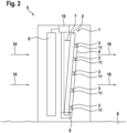
- Fig. 2 shows, by way of example and schematically, a sectional view of an external part of a heat pump 5.
- the external part of the heat pump 5 stands vertically on the ground 8 and has a fan 6 that is also aligned vertically.
- the fan 6 conveys ambient air through the heat exchanger 1 in a flow direction 10.
- the heat exchanger 1 can be tilted by an angle of attack 7, based on the vertical direction and/or the fan 6.
- the angle of attack 7 can be 5° [degrees], for example.
- condensate forming on the pipes 2 of the heat exchanger 1 can flow off on the side facing away from the fan 6 in the direction of the ground 8 and can thus reach the connecting devices 3, then the drain points 11 of the connecting devices 3 and then fed to the drain line 4.
- an outlet for the condensate can be provided in the housing of the outdoor part of the heat pump 5.
- a temperature sensor 9 can also be provided on the heat exchanger 1, with which a temperature is recorded in accordance with step a) of the method proposed here for frost protection of the heat exchanger 1.
- the temperature sensor 9 can be connected to a control and regulating device 12 that carries out a method proposed here.
- the drain guide 4 can have a heating device or be designed as a heating rod.
- step b) of the method proposed here after a limit value is undershot, which can indicate a forest hazard and can be stored in a memory of the control and regulating device 12, the heating device of the drain line 4 can be switched on and thus prevent the condensate from freezing or cause it to thaw.
- the control and regulating device 12 can also be electrically connected to the drain line 4 or a heating device arranged there.
Landscapes
- Engineering & Computer Science (AREA)
- Mechanical Engineering (AREA)
- General Engineering & Computer Science (AREA)
- Physics & Mathematics (AREA)
- Thermal Sciences (AREA)
- Chemical & Material Sciences (AREA)
- Combustion & Propulsion (AREA)
- Geometry (AREA)
- Heat-Exchange Devices With Radiators And Conduit Assemblies (AREA)
Claims (13)
- Échangeur de chaleur (1) pour une pompe à chaleur (5), présentant une pluralité de tubes (2) agencés dans l'état d'installation prévu le plus largement perpendiculairement et parallèlement et pouvant être traversés par un fluide caloporteur, qui sont reliés par le biais d'au moins un dispositif de liaison (3), dans lequel le au moins un dispositif de liaison (3) est agencé dans l'état d'installation le plus largement horizontalement et formé de telle manière que dans l'état d'installation, du condensat se formant au niveau des tubes (2) et s'écoulant vers le bas est acheminé sur le dispositif de liaison (3) et s'écoule en direction d'un point d'écoulement (11) du dispositif de liaison (3), caractérisé en ce qu'un dispositif de chauffage est prévu, lequel est conçu afin d'introduire de la chaleur dans le au moins un point d'écoulement (11).
- Échangeur de chaleur (1) selon la revendication 1, dans lequel au moins une section de l'au moins un dispositif de liaison (3) est formé en u ou en v.
- Échangeur de chaleur (1) selon l'une quelconque des revendications précédentes, dans lequel le au moins un point d'écoulement (11) présente un dispositif de dérivation qui est conçu afin d'éloigner le condensat s'écoulant des tubes (2) des tubes (2) de l'échangeur de chaleur (1).
- Échangeur de chaleur (1) selon la revendication 3, dans lequel le dispositif de dérivation est un cordon de soudure.
- Échangeur de chaleur (1) selon l'une quelconque des revendications précédentes, dans lequel plusieurs dispositifs de liaison (3) sont agencés en parallèle.
- Échangeur de chaleur (1) selon la revendication 5, présentant au moins un guidage d'écoulement (4) qui relie entre eux les points d'écoulement (11) des dispositifs de liaison (3).
- Échangeur de chaleur selon la revendication 6, dans lequel le guidage d'écoulement (4) est chauffable.
- Échangeur de chaleur selon la revendication 7, dans lequel le guidage d'écoulement (4) est une barre chauffante.
- Pompe à chaleur (5) présentant un échangeur de chaleur (1) selon l'une quelconque des revendications précédentes.
- Pompe à chaleur (1) selon la revendication 9, dans lequel l'échangeur de chaleur (1) est agencé dans la pompe à chaleur (5) de manière inclinée autour d'un angle d'attaque (7) de manière à favoriser un écoulement de condensat en direction du dispositif de liaison (3) en raison de la gravité.
- Procédé de protection antigel d'un échangeur de chaleur (1) selon l'une quelconque des revendications 1, 7 ou 8, comprenant au moins les étapes suivantes :a) la détection d'un paramètre qui autorise une conclusion à propos d'un gel ou d'une perméabilité réduite de l'échangeur de chaleur (1),b) la mise en service d'un dispositif de chauffage ou d'une barre chauffante qui introduit de la chaleur dans au moins un point d'écoulement (11) lorsque le paramètre détecté à l'étape a) se trouve sous une valeur limite.
- Programme informatique, comprenant des instructions qui, lorsque le programme est exécuté par un ordinateur, amènent celui-ci à exécuter le procédé selon la revendication 11.
- Pompe à chaleur (5) selon la revendication 9 ou 10 avec un appareil de régulation et de commande (12) conçu pour l'exécution d'un procédé selon la revendication 11.
Applications Claiming Priority (1)
| Application Number | Priority Date | Filing Date | Title |
|---|---|---|---|
| DE102021128714.6A DE102021128714A1 (de) | 2021-11-04 | 2021-11-04 | Wärmeübertrager, Wärmepumpe und Verfahren zur Forstsicherung eines Wärmeübertragers |
Publications (3)
| Publication Number | Publication Date |
|---|---|
| EP4177561A1 EP4177561A1 (fr) | 2023-05-10 |
| EP4177561B1 true EP4177561B1 (fr) | 2025-02-19 |
| EP4177561C0 EP4177561C0 (fr) | 2025-02-19 |
Family
ID=83899577
Family Applications (1)
| Application Number | Title | Priority Date | Filing Date |
|---|---|---|---|
| EP22202473.9A Active EP4177561B1 (fr) | 2021-11-04 | 2022-10-19 | Échangeur de chaleur, pompe à chaleur et procédé de sécurisation forestière d'un échangeur de chaleur |
Country Status (2)
| Country | Link |
|---|---|
| EP (1) | EP4177561B1 (fr) |
| DE (1) | DE102021128714A1 (fr) |
Family Cites Families (7)
| Publication number | Priority date | Publication date | Assignee | Title |
|---|---|---|---|---|
| US4041727A (en) * | 1975-09-02 | 1977-08-16 | Borg-Warner Corporation | Evaporator assembly |
| IL55047A0 (en) | 1977-07-22 | 1978-08-31 | Carrier Corp | Heat exchange system |
| DE10303595B4 (de) | 2003-01-30 | 2005-02-17 | Visteon Global Technologies, Inc., Dearborn | Mehrkanal-Wärmeübertrager- und Anschlusseinheit |
| CN102889820B (zh) * | 2012-10-15 | 2016-03-02 | 杭州三花微通道换热器有限公司 | 用于换热器的冷凝水导流结构以及换热器 |
| DK3012568T3 (en) * | 2014-10-20 | 2018-12-10 | Abb Schweiz Ag | Cooling device and cooled electrical device comprising it |
| DE102019000638B3 (de) | 2019-01-30 | 2020-06-25 | Hans-Peter Höcker | Hocheffiziente Hochtemperatur-Wärmepumpe zum Heizen und Kühlen von Gebäuden, mit einer Kombination von zylindrisch angeordneten Wärmetauschern, welche sich in einem Wärmespeicher befinden und durch ein flüssiges Speichermedium so angeströmt werden, dass eine zylindrische Kreisbewegung entsteht. |
| DE102019008908A1 (de) | 2019-12-20 | 2021-06-24 | Stiebel Eltron Gmbh & Co. Kg | Lüftungsgerät |
-
2021
- 2021-11-04 DE DE102021128714.6A patent/DE102021128714A1/de active Pending
-
2022
- 2022-10-19 EP EP22202473.9A patent/EP4177561B1/fr active Active
Also Published As
| Publication number | Publication date |
|---|---|
| DE102021128714A1 (de) | 2023-05-04 |
| EP4177561A1 (fr) | 2023-05-10 |
| EP4177561C0 (fr) | 2025-02-19 |
Similar Documents
| Publication | Publication Date | Title |
|---|---|---|
| EP3447403B1 (fr) | Procédures de fonctionnement pour installations de récupération de chaleur, unité d'échange de chaleur air/fluide et installation de récupération de chaleur | |
| DE10258455B4 (de) | Verdampfer für einen Kühlschrank und Kühlschrank mit Verdampfer | |
| EP3988881B1 (fr) | Procédé de fonctionnement d'un agencement d'échangeur de chaleur | |
| DE102006016557A1 (de) | Kühlfahrzeug mit externem Kühlmodul und Kühlverfahren | |
| DE102019111184B4 (de) | Kaltwärmenetz mit zwischengeschaltetem Latentwärmespeicher | |
| DE102012101271C5 (de) | Kühleinrichtung | |
| DE102015000636A1 (de) | Verfahren zum Enteisen eines Rotorblatts einer Windenergieanlage | |
| DE202021102235U1 (de) | System für gemeinsame Seitenanschlüsse für einen überdimensionierten Mehrplatten-Mikrokanal-Wärmeübertrager | |
| WO2016091883A1 (fr) | Système d'échange de chaleur, dispositif de dégivrage, ventilateur, échangeur de chaleur, boîtier et utilisation d'un vernis chauffant | |
| DE102006016558A1 (de) | Verfahren zum Überwachen der Gasdichtheit eines Kühlsystems eines Kühlfahrzeuges und zum Betreiben desselben sowie Kühlsystem für ein Kühlfahrzeug und Kühlfahrzeug | |
| EP3964761A1 (fr) | Procédé de dégivrage d'un composant exposé à l'air ambiant et dispositifs de mise en uvre du procédé | |
| EP4177561B1 (fr) | Échangeur de chaleur, pompe à chaleur et procédé de sécurisation forestière d'un échangeur de chaleur | |
| EP3572733A1 (fr) | Dispositif de chauffage à pompe à chaleur destiné à chauffer un immeuble ou accumulateur pour pompe à chaleur | |
| DE10139065A1 (de) | Vorrichtung zur Gewinnung von Wärmeenergie durch Nutzung der Latentwärme von Wasser und dafür geeigneter Wärmeaustauscher | |
| DE102006016555A1 (de) | Verfahren und Vorrichtung zum Aufbauen eines Überdrucks in einem Tank für verflüssigtes Gas eines Kühlfahrzeugs sowie Kühlsystem für ein Kühlfahrzeug und Kühlfahrzeug | |
| DE102019133587A1 (de) | Abtauen eines Wärmeübertragers bei Dachklimaanlagen | |
| DE8712814U1 (de) | Meßgaskühleinrichtung | |
| DE202012100838U1 (de) | Verdampfer insbesondere für einen Kältemittelkreislauf | |
| DE10243170A1 (de) | Heizungsanlage mit einer Wärmepumpe mit Kältemittelverflüssiger | |
| DE102012101980A1 (de) | Verdampfer insbesondere für einen kältemittelkreislauf | |
| DE60223941T2 (de) | Abluftwärmepumpe | |
| EP3480534B1 (fr) | Installation de chauffage et procédé de commande pour une installation de chauffage | |
| DE3902745C2 (de) | Wärmepumpenanlage | |
| AT504135A4 (de) | Verfahren zur wärmerückgewinnung | |
| DE3021464C2 (de) | Verfahren und Vorrichtung zum Klimatisieren von der Einwirkung natürlicher Wärmeeinstrahlung ausgesetzten Räumen |
Legal Events
| Date | Code | Title | Description |
|---|---|---|---|
| PUAI | Public reference made under article 153(3) epc to a published international application that has entered the european phase |
Free format text: ORIGINAL CODE: 0009012 |
|
| STAA | Information on the status of an ep patent application or granted ep patent |
Free format text: STATUS: THE APPLICATION HAS BEEN PUBLISHED |
|
| AK | Designated contracting states |
Kind code of ref document: A1 Designated state(s): AL AT BE BG CH CY CZ DE DK EE ES FI FR GB GR HR HU IE IS IT LI LT LU LV MC ME MK MT NL NO PL PT RO RS SE SI SK SM TR |
|
| STAA | Information on the status of an ep patent application or granted ep patent |
Free format text: STATUS: REQUEST FOR EXAMINATION WAS MADE |
|
| 17P | Request for examination filed |
Effective date: 20231106 |
|
| RBV | Designated contracting states (corrected) |
Designated state(s): AL AT BE BG CH CY CZ DE DK EE ES FI FR GB GR HR HU IE IS IT LI LT LU LV MC ME MK MT NL NO PL PT RO RS SE SI SK SM TR |
|
| STAA | Information on the status of an ep patent application or granted ep patent |
Free format text: STATUS: EXAMINATION IS IN PROGRESS |
|
| 17Q | First examination report despatched |
Effective date: 20240318 |
|
| GRAP | Despatch of communication of intention to grant a patent |
Free format text: ORIGINAL CODE: EPIDOSNIGR1 |
|
| STAA | Information on the status of an ep patent application or granted ep patent |
Free format text: STATUS: GRANT OF PATENT IS INTENDED |
|
| INTG | Intention to grant announced |
Effective date: 20241114 |
|
| GRAS | Grant fee paid |
Free format text: ORIGINAL CODE: EPIDOSNIGR3 |
|
| GRAA | (expected) grant |
Free format text: ORIGINAL CODE: 0009210 |
|
| STAA | Information on the status of an ep patent application or granted ep patent |
Free format text: STATUS: THE PATENT HAS BEEN GRANTED |
|
| AK | Designated contracting states |
Kind code of ref document: B1 Designated state(s): AL AT BE BG CH CY CZ DE DK EE ES FI FR GB GR HR HU IE IS IT LI LT LU LV MC ME MK MT NL NO PL PT RO RS SE SI SK SM TR |
|
| REG | Reference to a national code |
Ref country code: GB Ref legal event code: FG4D Free format text: NOT ENGLISH |
|
| REG | Reference to a national code |
Ref country code: CH Ref legal event code: EP |
|
| REG | Reference to a national code |
Ref country code: DE Ref legal event code: R096 Ref document number: 502022002930 Country of ref document: DE |
|
| REG | Reference to a national code |
Ref country code: IE Ref legal event code: FG4D Free format text: LANGUAGE OF EP DOCUMENT: GERMAN |
|
| U01 | Request for unitary effect filed |
Effective date: 20250310 |
|
| U07 | Unitary effect registered |
Designated state(s): AT BE BG DE DK EE FI FR IT LT LU LV MT NL PT RO SE SI Effective date: 20250317 |
|
| PG25 | Lapsed in a contracting state [announced via postgrant information from national office to epo] |
Ref country code: RS Free format text: LAPSE BECAUSE OF FAILURE TO SUBMIT A TRANSLATION OF THE DESCRIPTION OR TO PAY THE FEE WITHIN THE PRESCRIBED TIME-LIMIT Effective date: 20250519 |
|
| PG25 | Lapsed in a contracting state [announced via postgrant information from national office to epo] |
Ref country code: PL Free format text: LAPSE BECAUSE OF FAILURE TO SUBMIT A TRANSLATION OF THE DESCRIPTION OR TO PAY THE FEE WITHIN THE PRESCRIBED TIME-LIMIT Effective date: 20250219 |
|
| PG25 | Lapsed in a contracting state [announced via postgrant information from national office to epo] |
Ref country code: ES Free format text: LAPSE BECAUSE OF FAILURE TO SUBMIT A TRANSLATION OF THE DESCRIPTION OR TO PAY THE FEE WITHIN THE PRESCRIBED TIME-LIMIT Effective date: 20250219 |
|
| PG25 | Lapsed in a contracting state [announced via postgrant information from national office to epo] |
Ref country code: IS Free format text: LAPSE BECAUSE OF FAILURE TO SUBMIT A TRANSLATION OF THE DESCRIPTION OR TO PAY THE FEE WITHIN THE PRESCRIBED TIME-LIMIT Effective date: 20250619 Ref country code: NO Free format text: LAPSE BECAUSE OF FAILURE TO SUBMIT A TRANSLATION OF THE DESCRIPTION OR TO PAY THE FEE WITHIN THE PRESCRIBED TIME-LIMIT Effective date: 20250519 |
|
| PG25 | Lapsed in a contracting state [announced via postgrant information from national office to epo] |
Ref country code: HR Free format text: LAPSE BECAUSE OF FAILURE TO SUBMIT A TRANSLATION OF THE DESCRIPTION OR TO PAY THE FEE WITHIN THE PRESCRIBED TIME-LIMIT Effective date: 20250219 |
|
| PG25 | Lapsed in a contracting state [announced via postgrant information from national office to epo] |
Ref country code: GR Free format text: LAPSE BECAUSE OF FAILURE TO SUBMIT A TRANSLATION OF THE DESCRIPTION OR TO PAY THE FEE WITHIN THE PRESCRIBED TIME-LIMIT Effective date: 20250520 |
|
| PG25 | Lapsed in a contracting state [announced via postgrant information from national office to epo] |
Ref country code: SM Free format text: LAPSE BECAUSE OF FAILURE TO SUBMIT A TRANSLATION OF THE DESCRIPTION OR TO PAY THE FEE WITHIN THE PRESCRIBED TIME-LIMIT Effective date: 20250219 |
|
| PG25 | Lapsed in a contracting state [announced via postgrant information from national office to epo] |
Ref country code: CZ Free format text: LAPSE BECAUSE OF FAILURE TO SUBMIT A TRANSLATION OF THE DESCRIPTION OR TO PAY THE FEE WITHIN THE PRESCRIBED TIME-LIMIT Effective date: 20250219 |
|
| PG25 | Lapsed in a contracting state [announced via postgrant information from national office to epo] |
Ref country code: SK Free format text: LAPSE BECAUSE OF FAILURE TO SUBMIT A TRANSLATION OF THE DESCRIPTION OR TO PAY THE FEE WITHIN THE PRESCRIBED TIME-LIMIT Effective date: 20250219 |
|
| U20 | Renewal fee for the european patent with unitary effect paid |
Year of fee payment: 4 Effective date: 20250930 |
|
| PLBE | No opposition filed within time limit |
Free format text: ORIGINAL CODE: 0009261 |
|
| STAA | Information on the status of an ep patent application or granted ep patent |
Free format text: STATUS: NO OPPOSITION FILED WITHIN TIME LIMIT |
|
| 26N | No opposition filed |
Effective date: 20251120 |