EP4177656B1 - Linsenanordnung für ein bilderfassungssystem, abbildungsvorrichtung und elektronisches gerät - Google Patents
Linsenanordnung für ein bilderfassungssystem, abbildungsvorrichtung und elektronisches gerät Download PDFInfo
- Publication number
- EP4177656B1 EP4177656B1 EP22204681.5A EP22204681A EP4177656B1 EP 4177656 B1 EP4177656 B1 EP 4177656B1 EP 22204681 A EP22204681 A EP 22204681A EP 4177656 B1 EP4177656 B1 EP 4177656B1
- Authority
- EP
- European Patent Office
- Prior art keywords
- lens element
- image
- lens
- capturing system
- image capturing
- Prior art date
- Legal status (The legal status is an assumption and is not a legal conclusion. Google has not performed a legal analysis and makes no representation as to the accuracy of the status listed.)
- Active
Links
Images
















Classifications
-
- G—PHYSICS
- G02—OPTICS
- G02B—OPTICAL ELEMENTS, SYSTEMS OR APPARATUS
- G02B13/00—Optical objectives specially designed for the purposes specified below
- G02B13/001—Miniaturised objectives for electronic devices, e.g. portable telephones, webcams, PDAs, small digital cameras
- G02B13/0015—Miniaturised objectives for electronic devices, e.g. portable telephones, webcams, PDAs, small digital cameras characterised by the lens design
- G02B13/002—Miniaturised objectives for electronic devices, e.g. portable telephones, webcams, PDAs, small digital cameras characterised by the lens design having at least one aspherical surface
- G02B13/0045—Miniaturised objectives for electronic devices, e.g. portable telephones, webcams, PDAs, small digital cameras characterised by the lens design having at least one aspherical surface having five or more lenses
-
- G—PHYSICS
- G02—OPTICS
- G02B—OPTICAL ELEMENTS, SYSTEMS OR APPARATUS
- G02B13/00—Optical objectives specially designed for the purposes specified below
- G02B13/001—Miniaturised objectives for electronic devices, e.g. portable telephones, webcams, PDAs, small digital cameras
- G02B13/0055—Miniaturised objectives for electronic devices, e.g. portable telephones, webcams, PDAs, small digital cameras employing a special optical element
- G02B13/0065—Miniaturised objectives for electronic devices, e.g. portable telephones, webcams, PDAs, small digital cameras employing a special optical element having a beam-folding prism or mirror
-
- G—PHYSICS
- G02—OPTICS
- G02B—OPTICAL ELEMENTS, SYSTEMS OR APPARATUS
- G02B13/00—Optical objectives specially designed for the purposes specified below
- G02B13/18—Optical objectives specially designed for the purposes specified below with lenses having one or more non-spherical faces, e.g. for reducing geometrical aberration
-
- G—PHYSICS
- G02—OPTICS
- G02B—OPTICAL ELEMENTS, SYSTEMS OR APPARATUS
- G02B9/00—Optical objectives characterised both by the number of the components and their arrangements according to their sign, i.e. + or -
- G02B9/60—Optical objectives characterised both by the number of the components and their arrangements according to their sign, i.e. + or - having five components only
-
- G—PHYSICS
- G03—PHOTOGRAPHY; CINEMATOGRAPHY; ANALOGOUS TECHNIQUES USING WAVES OTHER THAN OPTICAL WAVES; ELECTROGRAPHY; HOLOGRAPHY
- G03B—APPARATUS OR ARRANGEMENTS FOR TAKING PHOTOGRAPHS OR FOR PROJECTING OR VIEWING THEM; APPARATUS OR ARRANGEMENTS EMPLOYING ANALOGOUS TECHNIQUES USING WAVES OTHER THAN OPTICAL WAVES; ACCESSORIES THEREFOR
- G03B17/00—Details of cameras or camera bodies; Accessories therefor
- G03B17/02—Bodies
- G03B17/17—Bodies with reflectors arranged in beam forming the photographic image, e.g. for reducing dimensions of camera
Definitions
- the present disclosure relates to an image capturing system lens assembly and an imaging apparatus. More particularly, the present disclosure relates to an image capturing system lens assembly and an imaging apparatus with compact size applicable to electronic devices.
- optical lens assemblies with high image quality have become an indispensable part of many modern electronics.
- applications of electronic devices equipped with optical lens assemblies increase and there is a wide variety of requirements for optical lens assemblies.
- it is hard to balance among image quality, sensitivity, aperture size, volume or field of view.
- the present disclosure provides an image capturing system lens assembly, which includes five lens elements.
- the five lens elements are, in order from an object side to an image side along an optical path, a first lens element, a second lens element, a third lens element, a fourth lens element and a fifth lens element.
- Each of the five lens elements has an object-side surface towards the object side and an image-side surface towards the image side.
- the object-side surface of the first lens element can be concave in a paraxial region thereof, which is favorable for enlarging field of view and reducing the effective radius of the first lens element.
- the second lens element can have positive refractive power, so that it is favorable for reducing the effective radius of the image capturing system lens assembly by cooperating with the first lens element.
- the object-side surface of the second lens element can be convex in a paraxial region thereof, so that it is favorable for correcting aberrations by adjusting the surface shape and refractive power of the second lens element.
- the image-side surface of the second lens element can be convex in a paraxial region thereof, so that it is favorable for enhancing the image quality in the central area by cooperating with the surface shape of the third lens element.
- the third lens element can have negative refractive power, which is favorable for correcting aberrations, such as spherical aberrations etc. by cooperating with the fourth lens element.
- the image-side surface of the fourth lens element can be convex in a paraxial region thereof, which is favorable for enhancing light converging quality in the paraxial region of the image capturing system lens assembly.
- the image-side surface of the fifth lens element can be concave in a paraxial region thereof, so that it is favorable for reducing the total track length of the image capturing system lens assembly by adjusting the back focal length thereof. Further, the image-side surface of the fifth lens element can include at least one critical point. Therefore, it is favorable for correcting the distortion of the peripheral field.
- At least one of the object-side surface and the image-side surface of at least one of the first lens element to the fifth lens element includes at least one inflection point. Therefore, it is favorable for enlarging the size of the image surface and reducing field curvature.
- At least one of the first lens element to the fifth lens element can be made of plastic material and can have the object-side surface and the image-side surface being both aspheric. Therefore, it is favorable for reducing the manufacturing cost and enhancing the image quality of the peripheral field.
- the first lens element belongs to a front lens group
- the second lens element, the third lens element, the fourth lens element and the fifth lens element belong to a rear lens group
- the displacing way of the rear lens group can be the displacement parallel to the optical axis, the displacement perpendicular with the optical axis, rotation etc., and the present disclosure will not be limited thereto.
- there is a relative displacement between the first lens element and the fifth lens element there is a relative displacement between the first lens element and the fifth lens element. Therefore, the relative position of the first lens element and the fifth lens element can be adjusted so as to provide different focal lengths for image capturing.
- the image capturing system lens assembly can further include a reflective element, which can be disposed between the first lens element and the fifth lens element. Therefore, it is favorable for obtaining compact size of the image capturing system lens assembly by folding the optical axis.
- the reflective element can be prism, mirror etc., and will not be limited thereto.
- the reflective element is prism, which can be made of glass or plastic etc.
- the incident surface of the prism can be planar or curved.
- the exiting surface of the prism can be planar or curved.
- the image capturing system lens assembly can further include an aperture stop.
- an axial distance between the aperture stop and the image surface is SL
- an axial distance between the object-side surface of the first lens element and the image surface is TL
- the following condition is satisfied: 0.74 ⁇ SL/TL ⁇ 1.50. Therefore, it is favorable for balancing the image size and the size of the front opening of the image capturing system lens assembly by adjusting the distance between the aperture stop and the image surface.
- the following condition can be satisfied: 0.75 ⁇ SLITL ⁇ 1.50.
- the following condition can be satisfied: 0.76 ⁇ SL/TL ⁇ 1.50.
- the following condition can be satisfied: 0.74 ⁇ SLITL ⁇ 1.05.
- the following condition can be satisfied: 0.80 ⁇ SL/TL ⁇ 0.98.
- the following condition is satisfied: 0.74 ⁇ T12/f ⁇ 1.40. Therefore, it is favorable for balancing the distribution of the volume of the image capturing system lens assembly by adjusting the arrangement of the lens elements. Further, the following condition can be satisfied: 0.80 ⁇ T12/f ⁇ 1.40. Furthermore, the following condition can be satisfied: 0.82 ⁇ T12/f ⁇ 1.38. Moreover, the following condition can be satisfied: 0.90 ⁇ T12/f ⁇ 1.20.
- a curvature radius of the object-side surface of the second lens element is R3, and a curvature radius of the image-side surface of the second lens element is R4, the following condition is satisfied: -1.05 ⁇ (R3+R4)/(R3-R4) ⁇ 0.70. Therefore, it is favorable for reducing the effective radius of the second lens element by adjusting the surface shape and the refractive power of the second lens element. Further, the following condition can be satisfied: -1.00 ⁇ (R3+R4)/(R3-R4) ⁇ 1.50. Furthermore, the following condition can be satisfied: -0.80 ⁇ (R3+R4)/(R3-R4) ⁇ 1.50. Moreover, the following condition can be satisfied: -0.80 ⁇ (R3+R4)/(R3-R4) ⁇ 0.50.
- a curvature radius of the object-side surface of the third lens element is R5
- a curvature radius of the image-side surface of the third lens element is R6
- the following condition is satisfied: -3.50 ⁇ (R5+R6)/(R5-R6) ⁇ 3.00. Therefore, it is favorable for enhancing the image quality of the central area by cooperating the third lens element with the second lens element. Further, the following condition can be satisfied: -2.70 ⁇ (R5+R6)/(R5-R6) ⁇ 2.70. Furthermore, the following condition can be satisfied: -2.40 ⁇ (R5+R6)/(R5-R6) ⁇ 2.50.
- the focal length of the image capturing system lens assembly is f
- a composite focal length of the fourth lens element and the fifth lens element is f45
- the following condition is satisfied: -2.50 ⁇ f/f45 ⁇ 1.04. Therefore, it is favorable for adjusting the back focal length by arranging the entire focal length of the fourth lens element and the fifth lens element. Further, the following condition can be satisfied: -2.50 ⁇ f/f45 ⁇ 0.88; or -2.00 ⁇ f/f45 ⁇ 0.88. Furthermore, the following condition can be satisfied: -1.00 ⁇ f/f45 ⁇ 0.70.
- the following condition is satisfied: -5.00 ⁇ f34/f45 ⁇ 3.60. Therefore, the entire focal length of the third lens element and the fourth lens element and the entire focal length of the fourth lens element and the fifth lens element can be adjusted, so that it is favorable for enhancing the light converging quality in the paraxial region by arranging the ratio of the refractive power of the rear end of the image capturing system lens assembly. Further, the following condition can be satisfied: -8.00 ⁇ f34/f45 ⁇ 2.02. Furthermore, the following condition can be satisfied: -4.00 ⁇ f34/f45 ⁇ 1.7.
- an axial distance between the second lens element and the third lens element is T23
- an axial distance between the third lens element and the fourth lens element is T34
- an axial distance between the fourth lens element and the fifth lens element is T45
- a central thickness of the second lens element is CT2
- a central thickness of the third lens element is CT3
- a central thickness of the fourth lens element is CT4
- a central thickness of the fifth lens element is CT5, the following condition is satisfied: 0.30 ⁇ (CT2+T23+CT3+T34+CT4+T45+CT5)/f ⁇ 3.40.
- the focal length of the image capturing system lens assembly is f
- a composite focal length of the first lens element and the second lens element is f12
- the following condition is satisfied: 0.40 ⁇ f/f12 ⁇ 2.00. Therefore, it is favorable for correcting the astigmatism of aberrations by adjusting the entire focal length of the first lens element and the second lens element. Further, the following condition can be satisfied: 0.60 ⁇ f/f12 ⁇ 1.50.
- a composite focal length of the first lens element, the second lens element and the third lens element is f123
- a composite focal length of the second lens element, the third lens element and the fourth lens element is f234
- the following condition is satisfied: -0.40 ⁇ f123/f234 ⁇ 1.85. Therefore, the entire refractive of the first lens element to the third lens element and the entire refractive of the second lens element to the fourth lens element can be adjusted, so that excessive geometric differences among the lens elements can be avoided by decreasing the ratio of refractive power so as to reduce the manufacturing difficulty. Further, the following condition can be satisfied: -0.20 ⁇ f123/f234 ⁇ 1.60.
- the focal length of the image capturing system lens assembly is f
- a maximum image height of the image capturing system lens assembly is ImgH
- the following condition is satisfied: 0.80 ⁇ f/ImgH ⁇ 2.25. Therefore, it is favorable for maintaining the image size by adjusting the ratio between the focal length and the image height. Further, the following condition can be satisfied: 0.80 ⁇ f/lmgH ⁇ 1.45. Furthermore, the following condition can be satisfied: 0.90 ⁇ f/ImgH ⁇ 2.10.
- the axial distance between the first lens element and the second lens element is T12
- the axial distance between the second lens element and the third lens element is T23
- the axial distance between the third lens element and the fourth lens element is T34
- the axial distance between the fourth lens element and the fifth lens element is T45
- the maximum among T12, T23, T34, T45 is ATmax
- the focal length of the image capturing system lens assembly is f
- the following condition is satisfied: 0.78 ⁇ ATmax/f ⁇ 9.00. Therefore, it is favorable for balancing the ratio of the distances among the lens elements and reducing the assembling error by adjusting the ratio between the focal length and the maximum distance between the lens elements. Further, the following condition can be satisfied: 0.85 ⁇ ATmax/f ⁇ 2.0.
- the axial distance between the first lens element and the second lens element is T12
- the axial distance between the second lens element and the third lens element is T23
- the axial distance between the third lens element and the fourth lens element is T34
- the axial distance between the fourth lens element and the fifth lens element is T45
- the maximum among T12, T23, T34, T45 is ATmax
- an axial distance between the image-side surface of the fifth lens element and the image surface is BL
- the following condition is satisfied: 2.00 ⁇ ATmax/BL ⁇ 7.00. Therefore, it is favorable for balancing the ratio of the distances among the lens elements and reducing the assembling error by adjusting the ratio between the back focal length and the maximum distance between the lens elements.
- the following condition can be satisfied: 2.0 ⁇ ATmax/BL ⁇ 3.5.
- the focal length of the image capturing system lens assembly is f
- a curvature radius of the object-side surface of the first lens element is R1
- the following condition is satisfied: -5.00 ⁇ f/R1 ⁇ 0.45. Therefore, it is favorable for enlarging field of view by adjusting refractive power of the image capturing system lens assembly and the surface shape of the first lens element. Further, the following condition can be satisfied: -2.50 ⁇ f/R1 ⁇ 0.35.
- the focal length of the image capturing system lens assembly is f
- a focal length of the second lens element is f2
- the following condition is satisfied: -0.60 ⁇ f/f2 ⁇ 3.00. Therefore, it is favorable for enhancing light converging quality by adjusting refractive power of the second lens element. Further, the following condition can be satisfied: -0.30 ⁇ f/f2 ⁇ 2.0. Furthermore, the following condition can be satisfied: 0.30 ⁇ f/f2 ⁇ 1.80.
- the focal length of the image capturing system lens assembly is f
- a focal length of the third lens element is f3
- the following condition is satisfied: -2.00 ⁇ f/f3 ⁇ 0.85. Therefore, it is favorable for reducing spherical aberration by adjusting refractive power of the third lens element and cooperating with the fourth lens element. Further, the following condition can be satisfied: -1.50 ⁇ f/f3 ⁇ 0.
- the following condition is satisfied: 0 ⁇ T45/f ⁇ 0.90. Therefore, it is favorable for balancing the ratio between the total track length and the back focal length by adjusting the ratio of distance between the fourth lens element and the fifth lens element to the focal length. Further, the following condition can be satisfied: 0 ⁇ T45/f ⁇ 0.60. Furthermore, the following condition can be satisfied: 0 ⁇ T45/f ⁇ 0.30. Moreover, the following condition can be satisfied: 0 ⁇ T45/f ⁇ 0.10.
- the image capturing system lens assembly When a maximum field of view of the image capturing system lens assembly is FOV, the following condition is satisfied: 50 degrees ⁇ FOV ⁇ 120 degrees. Therefore, the image capturing system lens assembly can obtain characteristic of wide field of view, and aberrations, such as distortion etc., due to the excessive field of view can be reduced. Further, the following condition can be satisfied: 65 degrees ⁇ FOV ⁇ 105 degrees.
- the axial distance between the second lens element and the third lens element is T23
- the axial distance between the third lens element and the fourth lens element is T34
- the axial distance between the fourth lens element and the fifth lens element is T45
- a sum of all axial distances between adjacent lens elements of the image capturing system lens assembly is ⁇ AT
- the following condition is satisfied: 0.10 ⁇ (T23+T34+T45)/ ⁇ AT ⁇ 0.50. Therefore, it is favorable for reducing the total track length of the image capturing system lens assembly by adjusting the distance ratio among the second lens element to the fifth lens element. Further, the following condition can be satisfied: 0.12 ⁇ (T23+T34+T45)/ ⁇ AT ⁇ 0.5.
- the focal length of the image capturing system lens assembly is f
- the curvature radius of the object-side surface of the second lens element is R3
- the following condition is satisfied: 0.70 ⁇ f/R3 ⁇ 1.81. Therefore, it is favorable for reducing the effective radius of the second lens element by adjusting the refractive power of the image capturing system lens assembly and the surface shape of the second lens element.
- the focal length of the image capturing system lens assembly is f
- the curvature radius of the image-side surface of the second lens element is R4
- the following condition is satisfied: -2.50 ⁇ f/R4 ⁇ -0.50. Therefore, it is favorable for correcting spherical aberration of the central field by adjusting refractive power of the image capturing system lens assembly and the surface shape of the second lens element. Further, the following condition can be satisfied: -2.70 ⁇ f/R4 ⁇ -0.40.
- a curvature radius of the object-side surface of the fourth lens element is R7
- a curvature radius of the image-side surface of the fourth lens element is R8, the following condition is satisfied: -1.00 ⁇ (R7-R8)/(R7+R8) ⁇ 1.00. Therefore, the surface shape and refractive power of the fourth lens element can be adjusted so as to improve chromatic aberration of the central region.
- a refractive index of the third lens element is N3
- a refractive index of the fifth lens element is N5
- the following condition is satisfied: 1.60 ⁇ (N3+N5)/2 ⁇ 1.90. Therefore, the average of the refractive indices of the third lens element and the fifth lens element can be adjusted so as to expand the image size.
- the curvature radius of the object-side surface of the first lens element is R1
- the curvature radius of the image-side surface of the first lens element is R2
- the following condition is satisfied: -1.00 ⁇ (R1-R2)/(R1+R2) ⁇ 1.00. Therefore, it is favorable for increasing field of view by adjusting the focal length of the lens elements on the front end of the image capturing system lens assembly.
- the axial distance between the aperture stop and the image surface is SL
- the axial distance between the object-side surface of the first lens element and the image surface is TL
- the focal length of the image capturing system lens assembly is f
- the following condition is satisfied: 0.30 ⁇ (TL-SL)/f ⁇ 0.85. Therefore, it is favorable for balancing the length of the front end of the image capturing system lens assembly and field of view by adjusting the distance between the opening of the image capturing system lens assembly and the aperture stop. Further, the following condition can be satisfied: 0.45 ⁇ (TL-SL)/f ⁇ 0.71.
- the maximum distance between the optical effective region of the object-side surface of the first lens element and the optical axis is Y11
- the axial distance between the first lens element and the second lens element is T12
- the axial distance between the second lens element and the third lens element is T23
- the axial distance between the third lens element and the fourth lens element is T34
- the axial distance between the fourth lens element and the fifth lens element is T45
- the maximum among T12, T23, T34, T45 is ATmax
- the following condition is satisfied: 1.80 ⁇ ATmax/Y11 ⁇ 3.40. Therefore, it is favorable for reducing the opening size and screen-to-body ratio by adjusting the ratio between the effective radius of the first lens element and the maximum distance between the lens elements. Further, the following condition can be satisfied: 2.00 ⁇ ATmax/Y11 ⁇ 3.00.
- the maximum distance between the optical effective region of the object-side surface of the first lens element and the optical axis is Y11
- the maximum image height of the image capturing system lens assembly is ImgH
- the following condition is satisfied: 0.34 ⁇ Y11/ImgH ⁇ 0.70. Therefore, it is favorable for enhancing the compactness of the electronic device and reducing screen-to-body ratio by adjusting the ratio between the opening of the image capturing system lens assembly and the image size. Further, the following condition can be satisfied: 0.42 ⁇ Y11/ImgH ⁇ 0.62.
- a central thickness of the first lens element is CT1
- the central thickness of the second lens element is CT2
- the central thickness of the third lens element is CT3
- the central thickness of the fourth lens element is CT4
- the central thickness of the fifth lens element is CT5, and a maximum among CT1, CT2, CT3, CT4, CT5 is CTmax
- the following condition is satisfied: 0.50 ⁇ CT1/CTmax ⁇ 1.0. Therefore, it is favorable for reducing the effective radius of the second lens element and the thickness of the electronic device by adjusting the ratio between the thickness of the first lens element and the maximum thickness. Further, the following condition can be satisfied: 0.70 ⁇ CT1/CTmax ⁇ 1.0. Furthermore, the following condition can be satisfied: 0.80 ⁇ CT1/CTmax ⁇ 1.0.
- the lens elements thereof can be made of glass or plastic materials.
- the glass lens element can either be made by grinding or molding.
- manufacturing costs can be effectively reduced.
- surfaces of each lens element can be arranged to be aspheric (ASP), since the aspheric surface of the lens element is easy to form a shape other than a spherical surface so as to have more controllable variables for eliminating aberrations thereof, and to further decrease the required amount of lens elements in the image capturing system lens assembly. Therefore, the total track length of the image capturing system lens assembly can also be reduced.
- the aspheric surfaces may be formed by a plastic injection molding method, a glass molding method or other manufacturing methods.
- additives can be selectively added into any one (or more) material of the lens elements so as to change the transmittance of the lens element in a particular wavelength range. Therefore, the stray light and chromatic aberration can be reduced.
- the additives can have the absorption ability for light in a wavelength range of 600 nm - 800 nm in the image capturing system lens assembly so as to reduce extra red light or infrared light, or the additives can have the absorption ability for light in a wavelength range of 350 nm - 450 nm in the image capturing system lens assembly so as to reduce blue light or ultraviolet light. Therefore, additives can prevent the image from interfering by light in a particular wavelength range.
- the additives can be homogeneously mixed with the plastic material, and the lens elements can be made by the injection molding method.
- the additives can be coated on the lens surfaces to provide the aforementioned effects.
- the image capturing system lens assembly of the present disclosure when a surface of the lens element is aspheric, it indicates that entire optical effective region of the surface of the lens element or a part thereof is aspheric.
- the lens elements when the lens elements have surfaces being convex and the convex surface position is not defined, it indicates that the aforementioned surfaces of the lens elements can be convex in the paraxial region thereof.
- the lens elements When the lens elements have surfaces being concave and the concave surface position is not been defined, it indicates that the aforementioned surfaces of the lens elements can be concave in the paraxial region thereof.
- the lens element has positive refractive power or negative refractive power, or the focal length of the lens element, all can be referred to the refractive power, or the focal length, in the paraxial region of the lens element.
- a critical point is a non-axial point of the lens surface where its tangent is perpendicular to the optical axis; an inflection point is a point on a lens surface with a curvature changing from positive to negative or from negative to positive.
- the image surface thereof based on the corresponding image sensor, can be flat or curved.
- the image surface can be a concave curved surface facing towards the object side.
- the image capturing system lens assembly of the present disclosure can selectively include at least one image correcting element (such as a field flattener) inserted between the lens element closest to the image surface and the image surface, thus the effect of correcting image aberrations (such as field curvature) can be achieved.
- the optical properties of the aforementioned image correcting element can be adjusted corresponding to the demands of the imaging apparatus.
- a preferred configuration of the image correcting element is to dispose a thin plano-concave element having a concave surface toward the object side on the position closed to the image surface.
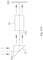
- Fig. 31A is a schematic view of an arrangement of a light path folding element LF in the image capturing system lens assembly of the present disclosure.
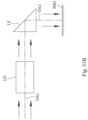
- Fig. 31B is a schematic view of another arrangement of the light path folding element LF in the image capturing system lens assembly of the present disclosure. As shown in Figs.
- the image capturing system lens assembly includes, in order from an imaged object (not shown in drawings) to an image surface IMG, a first optical axis OA1, the light path folding element LF and a second optical axis OA2, wherein the light path folding element LF can be disposed between the imaged object and a lens group LG of the image capturing system lens assembly as shown in Fig. 31A , or can be disposed between the lens group LG of the image capturing system lens assembly and the image surface IMG as shown in Fig. 31B .
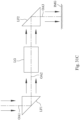
- Fig. 31C is a schematic view of an arrangement of two light path folding elements LF1, LF2 in the image capturing system lens assembly of the present disclosure. As shown in Fig.
- the image capturing system lens assembly includes, in order from an imaged object (not shown in drawings) to an image surface IM, a first optical axis OA1, the light path folding element LF1, a second optical axis OA2, the light path folding element LF2 and a third optical axis OA3, wherein the light path folding element LF1 is disposed between the imaged object and a lens group LG of the image capturing system lens assembly, and the light path folding element LF2 is disposed between the lens group LG of the image capturing system lens assembly and the image surface IMG.
- the image capturing system lens assembly can also be selectively disposed with three or more light path folding element, the type, amount and location of the light path folding element will not be limited to the present disclosure.
- the image capturing system lens assembly can include at least one stop, such as an aperture stop, a glare stop or a field stop, for eliminating stray light and thereby improving image resolution thereof.
- at least one stop such as an aperture stop, a glare stop or a field stop, for eliminating stray light and thereby improving image resolution thereof.
- the aperture stop can be configured as a front stop or a middle stop, wherein the front stop indicates that the aperture stop is disposed between an object and the first lens element, and the middle stop indicates that the aperture stop is disposed between the first lens element and the image surface.
- the aperture stop is a front stop, a longer distance between an exit pupil of the image capturing system lens assembly and the image surface can be obtained, and thereby obtains a telecentric effect and improves the image-sensing efficiency of the image sensor, such as CCD or CMOS.
- the middle stop is favorable for enlarging the field of view of the image capturing system lens assembly and thereby provides a wider field of view for the same.
- an aperture control unit can be properly configured.
- the aperture control unit can be a mechanical element or a light controlling element, and the dimension and the shape of the aperture control unit can be electrically controlled.
- the mechanical element can include a moveable component such a blade group or a shielding plate.
- the light controlling element can include a screen component such as a light filter, an electrochromic material, a liquid crystal layer or the like.
- the amount of incoming light or the exposure time of the image can be controlled by the aperture control unit to enhance the image moderation ability.
- the aperture control unit can be the aperture stop of the image capturing system lens assembly according to the present disclosure, so as to moderate the image quality by changing f-number such as changing the depth of field or the exposure speed.
- the image capturing system lens assembly of the present disclosure can be applied to 3D (three-dimensional) image capturing applications, in products such as digital cameras, mobile devices, digital tablets, smart TVs, surveillance systems, motion sensing input devices, driving recording systems, rearview camera systems, wearable devices, unmanned aerial vehicles, and other electronic imaging products.
- products such as digital cameras, mobile devices, digital tablets, smart TVs, surveillance systems, motion sensing input devices, driving recording systems, rearview camera systems, wearable devices, unmanned aerial vehicles, and other electronic imaging products.
- an imaging apparatus including the aforementioned image capturing system lens assembly and an image sensor is provided, wherein the image sensor is disposed on the image surface of the image capturing system lens assembly.
- the imaging apparatus can further include a barrel member, a holder member or a combination thereof.
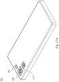
- an electronic device including the aforementioned imaging apparatus is provided. Therefore, the image quality can be increased.
- the electronic device can further include a control unit, a display, a storage unit, a random-access memory unit (RAM) or a combination thereof.
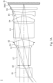
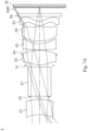
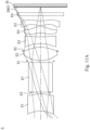
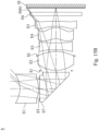
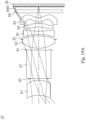
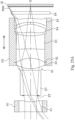
- Fig. 1A is a schematic view of an imaging apparatus 1 according to the 1st embodiment of the present disclosure.
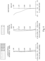
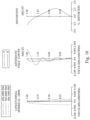
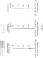
- Fig. 2 shows spherical aberration curves, astigmatic field curves and a distortion curve of the imaging apparatus 1 according to the 1st embodiment.
- the imaging apparatus 1 includes an image capturing system lens assembly (its reference numeral is omitted) and an image sensor IS.
- the image capturing system lens assembly includes, in order from an object side to an image side along an optical path, a first lens element E1, an aperture stop ST, a reflective element E7, a stop S1, a second lens element E2, a stop S2, a third lens element E3, a fourth lens element E4, a fifth lens element E5, a filter E6 and an image surface IMG, wherein the image sensor IS is disposed on the image surface IMG of the image capturing system lens assembly.
- the image capturing system lens assembly includes five lens elements (E1, E2, E3, E4, E5) without additional one or more lens elements inserted between the first lens element E1 and the fifth lens element E5.
- the first lens element E1 with negative refractive power has an object-side surface being convex in a paraxial region thereof and an image-side surface being concave in a paraxial region thereof.
- the first lens element E1 is made of a plastic material, and has the object-side surface and the image-side surface being both aspheric.
- Fig. 23A is a schematic view of partial parameters, the inflection points IP of each lens element and the critical points CP according to the 1st embodiment.
- the object-side surface of the first lens element E1 includes one inflection point IP
- the image-side surface of the first lens element E1 includes one inflection point IP.
- the second lens element E2 with positive refractive power has an object-side surface being convex in a paraxial region thereof and an image-side surface being convex in a paraxial region thereof.
- the second lens element E2 is made of a plastic material, and has the object-side surface and the image-side surface being both aspheric. Furthermore, the object-side surface of the second lens element E2 includes one inflection point IP (as shown in Fig. 23A ).
- the third lens element E3 with negative refractive power has an object-side surface being concave in a paraxial region thereof and an image-side surface being concave in a paraxial region thereof.
- the third lens element E3 is made of a plastic material, and has the object-side surface and the image-side surface being both aspheric. Furthermore, the object-side surface of the third lens element E3 includes one inflection point IP (as shown in Fig. 23A ), and the image-side surface of the third lens element E3 includes two inflection points IP (as shown in Fig. 23A ).
- the fourth lens element E4 with negative refractive power has an object-side surface being concave in a paraxial region thereof and an image-side surface being convex in a paraxial region thereof.
- the fourth lens element E4 is made of a plastic material, and has the object-side surface and the image-side surface being both aspheric. Furthermore, the object-side surface of the fourth lens element E4 includes one inflection point IP (as shown in Fig. 23A ), and the image-side surface of the fourth lens element E4 includes three inflection points IP (as shown in Fig. 23A ).
- the fifth lens element E5 with positive refractive power has an object-side surface being convex in a paraxial region thereof and an image-side surface being convex in a paraxial region thereof.
- the fifth lens element E5 is made of a plastic material, and has the object-side surface and the image-side surface being both aspheric. Furthermore, the object-side surface of the fifth lens element E5 includes three inflection points IP (as shown in Fig. 23A ), and the image-side surface of the fifth lens element E5 includes three inflection points IP and one critical point (as shown in Fig. 23A ).
- the reflective element E7 is a prism, which is made of glass material and disposed between the first lens element E1 and the second lens element E2.
- the filter E6 is made of a glass material, which is located between the fifth lens element E5 and the image surface IMG in order, and will not affect the focal length of the image capturing system lens assembly.
- a central thickness of the first lens element E1 is CT1
- a central thickness of the second lens element E2 is CT2
- a central thickness of the third lens element E3 is CT3
- a central thickness of the fourth lens element E4 is CT4
- the central thickness of the second lens element E2 is CT2
- the central thickness of the third lens element E3 is CT3
- the central thickness of the fourth lens element E4 is CT4
- the central thickness of the fifth lens element E5 is CT5
- the focal length of the image capturing system lens assembly is f
- a curvature radius of the object-side surface of the first lens element E1 is R1
- a curvature radius of the object-side surface of the second lens element E2 is R3
- a curvature radius of the image-side surface of the second lens element E2 is R4
- the focal length of the image capturing system lens assembly is f
- the maximum image height of the image capturing system lens assembly is ImgH
- the focal length of the image capturing system lens assembly is f
- the axial distance between the object-side surface of the first lens element E1 and the image surface IMG is TL
- the axial distance between the aperture stop ST and the image surface IMG is SL
- a maximum distance between the optical effective region of the object-side surface of the first lens element E1 and the optical axis is Y11
- a maximum distance between an optical effective region of the image-side surface of the fifth lens element E5 and the optical axis is Y52
- a maximum image height of the image capturing system lens assembly is ImgH
- Table 1A The detailed optical data of the 1st embodiment are shown in Table 1A and the aspheric surface data are shown in Table 1B below.
- Effective radius of Surface 6 (stop S1) is 0.880 mm. Effective radius of Surface 9 (stop S2) is 1.140 mm.
- Table 1B - Aspheric Coefficients Surface # 1 2 7 8 10 k -2.3431800E+01 -1.7197400E+01 -7.9061200E-01 1.1809100E+00 -9.0000000E+01
- Table 1A the curvature radius, the thickness and the focal length are shown in millimeters (mm).
- Surface numbers 0-18 represent the surfaces sequentially arranged from the object side to the image side along the optical axis.
- Table 1B k represents the conic coefficient of the equation of the aspheric surface profiles.
- A4-A22 represent the aspheric coefficients ranging from the 4th order to the 22th order.
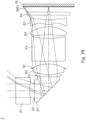
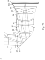
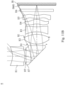
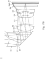
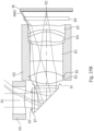
- Fig. 1B is a schematic view of the imaging apparatus 1 with another reflective element E7 according to the 1st embodiment of the present disclosure
- Fig. 23B is a schematic view of partial parameters, the inflection points IP of each lens element and the critical points CP according to the 1st embodiment of Fig. 1B
- the difference between the Fig. 1B , Fig. 23B and Fig. 1A , Fig. 23A is that the reflective element E7 of Fig. 1B and Fig. 23B can fold the direction of the optical axis, so that the arrangement is favorable for adapting the electronic device with different requirements.
- Fig. 25A is a schematic view of the imaging apparatus 1 according to the 1st embodiment of Fig. 1A which is arranged with lens barrels G1, G2, and Fig. 25B is a schematic view of the imaging apparatus 1 according to the 1st embodiment of Fig. 1B which is arranged with lens barrels G1, G2.
- the first lens element E1 is disposed in the lens barrel G1 which belongs to a front lens group.
- the second lens element E2, the third lens element E3, the fourth lens element E4 and the fifth lens element E5 are disposed in the lens barrel G2 which are belong to a rear lens group. There is a relative displacement between the rear lens group and the front lens group.
- Fig. 25A is a schematic view of the imaging apparatus 1 according to the 1st embodiment of Fig. 1A which is arranged with lens barrels G1, G2
- the first lens element E1 is disposed in the lens barrel G1 which belongs to a front lens group.
- the rear lens group is displaced along the optical axis X relative to the front lens group, and there is a relative displacement between the first lens element E1 and the fifth lens element E5.
- the rear lens group is displaced along a second optical axis X2 relative to the front lens group due to a first optical axis X1 is folded into the second optical axis X2 by the reflective E7; that is the rear lens group is displaced along a direction perpendicular with the first optical axis X1 relative to the front lens group.
- Fig. 3A is a schematic view of an imaging apparatus 2 according to the 2nd embodiment of the present disclosure.
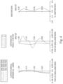
- Fig. 4 shows spherical aberration curves, astigmatic field curves and a distortion curve of the imaging apparatus 2 according to the 2nd embodiment.
- the imaging apparatus 2 includes an image capturing system lens assembly (its reference numeral is omitted) and an image sensor IS.
- the image capturing system lens assembly includes, in order from an object side to an image side along an optical path, a first lens element E1, an aperture stop ST, a reflective element E7, a stop S1, a second lens element E2, a stop S2, a third lens element E3, a fourth lens element E4, a fifth lens element E5, a filter E6 and an image surface IMG, wherein the image sensor IS is disposed on the image surface IMG of the image capturing system lens assembly.
- the image capturing system lens assembly includes five lens elements (E1, E2, E3, E4, E5) without additional one or more lens elements inserted between the first lens element E1 and the fifth lens element E5.
- the first lens element E1 with negative refractive power has an object-side surface being convex in a paraxial region thereof and an image-side surface being concave in a paraxial region thereof.
- the first lens element E1 is made of a plastic material, and has the object-side surface and the image-side surface being both aspheric. Furthermore, the object-side surface of the first lens element E1 includes one inflection point, and the image-side surface of the first lens element E1 includes one inflection point.
- the second lens element E2 with positive refractive power has an object-side surface being convex in a paraxial region thereof and an image-side surface being convex in a paraxial region thereof.
- the second lens element E2 is made of a plastic material, and has the object-side surface and the image-side surface being both aspheric. Furthermore, the object-side surface of the second lens element E2 includes one inflection point.
- the third lens element E3 with negative refractive power has an object-side surface being convex in a paraxial region thereof and an image-side surface being concave in a paraxial region thereof.
- the third lens element E3 is made of a plastic material, and has the object-side surface and the image-side surface being both aspheric. Furthermore, the object-side surface of the third lens element E3 includes two inflection points, and the image-side surface of the third lens element E3 includes two inflection points.
- the fourth lens element E4 with positive refractive power has an object-side surface being concave in a paraxial region thereof and an image-side surface being convex in a paraxial region thereof.
- the fourth lens element E4 is made of a plastic material, and has the object-side surface and the image-side surface being both aspheric. Furthermore, the object-side surface of the fourth lens element E4 includes three inflection points, and the image-side surface of the fourth lens element E4 includes three inflection points.
- the fifth lens element E5 with positive refractive power has an object-side surface being convex in a paraxial region thereof and an image-side surface being concave in a paraxial region thereof.
- the fifth lens element E5 is made of a plastic material, and has the object-side surface and the image-side surface being both aspheric. Furthermore, the object-side surface of the fifth lens element E5 includes one inflection point, and the image-side surface of the fifth lens element E5 includes four inflection points and two critical points.
- the reflective element E7 is a prism, which is made of glass material and disposed between the first lens element E1 and the second lens element E2.
- the filter E6 is made of a glass material, which is located between the fifth lens element E5 and the image surface IMG in order, and will not affect the focal length of the image capturing system lens assembly.
- Table 2A The detailed optical data of the 2nd embodiment are shown in Table 2A and the aspheric surface data are shown in Table 2B below.
- Effective radius of Surface 6 (stop S1) is 0.840 mm. Effective radius of Surface 9 (stop S2) is 1.140 mm.
- Table 2B - Aspheric Coefficients Surface # 1 2 7 8 10 k 2.1208600E+01 -5.3522400E+01 -1.7243500E+00 3.0908000E+00 3.8717700E+01
- A4 -1.0192138E-01 2.7997745E-01 -1.4769582E-01 -2.3797074E-01 -1.6073625E-01
- A6 3.6402271E-01 1.5309626E-01 7.0686388E-01 1.1132251E+00 4.6031623E-01
- A8 -1.5748152E+00 -1.3503865E+01 -2.3619497E+00 -2.8783062E+00 -7.4751648E-01
- A10 3.9164661E+00 9.6509359E+01 4.6740386E+00 4.2366057E+00 -
- the equation of the aspheric surface profiles of the aforementioned lens elements is the same as the equation of the 1st embodiment. Also, the definitions of these parameters shown in the following table are the same as those stated in the 1st embodiment with corresponding values for the 2nd embodiment, so an explanation in this regard will not be provided again.
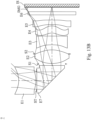
- Fig. 3B is a schematic view of the imaging apparatus 2 with another reflective element E7 according to the 2nd embodiment of the present disclosure.
- the difference between the Fig. 3B and Fig. 3A is that the reflective element E7 of Fig. 3B can fold the direction of the optical axis, so that the arrangement is favorable for adapting the electronic device with different requirements.
- Fig. 5A is a schematic view of an imaging apparatus 3 according to the 3rd embodiment of the present disclosure.
- Fig. 6 shows spherical aberration curves, astigmatic field curves and a distortion curve of the imaging apparatus 3 according to the 3rd embodiment.
- the imaging apparatus 3 includes an image capturing system lens assembly (its reference numeral is omitted) and an image sensor IS.
- the image capturing system lens assembly includes, in order from an object side to an image side along an optical path, a first lens element E1, an aperture stop ST, a reflective element E7, a stop S1, a second lens element E2, a stop S2, a third lens element E3, a fourth lens element E4, a fifth lens element E5, a filter E6 and an image surface IMG, wherein the image sensor IS is disposed on the image surface IMG of the image capturing system lens assembly.
- the image capturing system lens assembly includes five lens elements (E1, E2, E3, E4, E5) without additional one or more lens elements inserted between the first lens element E1 and the fifth lens element E5.
- the first lens element E1 with negative refractive power has an object-side surface being concave in a paraxial region thereof and an image-side surface being convex in a paraxial region thereof.
- the first lens element E1 is made of a plastic material, and has the object-side surface and the image-side surface being both aspheric.
- the second lens element E2 with positive refractive power has an object-side surface being convex in a paraxial region thereof and an image-side surface being convex in a paraxial region thereof.
- the second lens element E2 is made of a plastic material, and has the object-side surface and the image-side surface being both aspheric. Furthermore, the object-side surface of the second lens element E2 includes one inflection point.
- the third lens element E3 with negative refractive power has an object-side surface being convex in a paraxial region thereof and an image-side surface being concave in a paraxial region thereof.
- the third lens element E3 is made of a plastic material, and has the object-side surface and the image-side surface being both aspheric. Furthermore, the object-side surface of the third lens element E3 includes two inflection points.
- the fourth lens element E4 with positive refractive power has an object-side surface being convex in a paraxial region thereof and an image-side surface being convex in a paraxial region thereof.
- the fourth lens element E4 is made of a plastic material, and has the object-side surface and the image-side surface being both aspheric. Furthermore, the image-side surface of the fourth lens element E4 includes one inflection point.
- the fifth lens element E5 with positive refractive power has an object-side surface being convex in a paraxial region thereof and an image-side surface being concave in a paraxial region thereof.
- the fifth lens element E5 is made of a plastic material, and has the object-side surface and the image-side surface being both aspheric. Furthermore, the object-side surface of the fifth lens element E5 includes one inflection point, and the image-side surface of the fifth lens element E5 includes one inflection point.
- the reflective element E7 is a prism, which is made of glass material and disposed between the first lens element E1 and the second lens element E2.
- the filter E6 is made of a glass material, which is located between the fifth lens element E5 and the image surface IMG in order, and will not affect the focal length of the image capturing system lens assembly.
- Effective radius of Surface 6 (stop S1) is 0.890 mm. Effective radius of Surface 9 (stop S2) is 1.150 mm.
- Table 3B - Aspheric Coefficients Surface # 1 2 7 8 10 k 8.1024300E+00 2.8846500E+01 -8.5911000E-01 3.1871100E+00 7.2305700E+01
- A4 3.0821857E-02 -1.9381584E-02 -7.8869193E-03 2.3741379E-02 -1.1585322E-01
- A6 -1.1826878E-01 1.1898970E-01 1.7794505E-03 8.8004665E-02 1.4327133E-01
- A8 7.7199476E-01 -1.5662106E+00 -6.4446851E-02 -1.8989793E-02 1.2559841E-03
- A10 -2.6038638E+00 9.9943914E+00 1.7066787E-01 -2.4620242
- the equation of the aspheric surface profiles of the aforementioned lens elements is the same as the equation of the 1st embodiment. Also, the definitions of these parameters shown in the following table are the same as those stated in the 1st embodiment with corresponding values for the 3rd embodiment, so an explanation in this regard will not be provided again.
- Fig. 5B is a schematic view of the imaging apparatus 3 with another reflective element E7 according to the 3rd embodiment of the present disclosure.
- the difference between the Fig. 5B and Fig. 5A is that the reflective element E7 of Fig. 5B can fold the direction of the optical axis, so that the arrangement is favorable for adapting the electronic device with different requirements.
- Fig. 7A is a schematic view of an imaging apparatus 4 according to the 4th embodiment of the present disclosure.
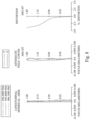
- Fig. 8 shows spherical aberration curves, astigmatic field curves and a distortion curve of the imaging apparatus 4 according to the 4th embodiment.
- the imaging apparatus 4 includes an image capturing system lens assembly (its reference numeral is omitted) and an image sensor IS.
- the image capturing system lens assembly includes, in order from an object side to an image side along an optical path, a first lens element E1, an aperture stop ST, a reflective element E7, a stop S1, a second lens element E2, a stop S2, a third lens element E3, a fourth lens element E4, a fifth lens element E5, a filter E6 and an image surface IMG, wherein the image sensor IS is disposed on the image surface IMG of the image capturing system lens assembly.
- the image capturing system lens assembly includes five lens elements (E1, E2, E3, E4, E5) without additional one or more lens elements inserted between the first lens element E1 and the fifth lens element E5.
- the first lens element E1 with negative refractive power has an object-side surface being concave in a paraxial region thereof and an image-side surface being convex in a paraxial region thereof.
- the first lens element E1 is made of a plastic material, and has the object-side surface and the image-side surface being both aspheric.
- the second lens element E2 with positive refractive power has an object-side surface being convex in a paraxial region thereof and an image-side surface being convex in a paraxial region thereof.
- the second lens element E2 is made of a plastic material, and has the object-side surface and the image-side surface being both aspheric. Furthermore, the object-side surface of the second lens element E2 includes one inflection point.
- the third lens element E3 with negative refractive power has an object-side surface being convex in a paraxial region thereof and an image-side surface being concave in a paraxial region thereof.
- the third lens element E3 is made of a plastic material, and has the object-side surface and the image-side surface being both aspheric. Furthermore, the object-side surface of the third lens element E3 includes two inflection points, and the image-side surface of the third lens element E3 includes two inflection points.
- the fourth lens element E4 with negative refractive power has an object-side surface being convex in a paraxial region thereof and an image-side surface being concave in a paraxial region thereof.
- the fourth lens element E4 is made of a plastic material, and has the object-side surface and the image-side surface being both aspheric. Furthermore, the image-side surface of the fourth lens element E4 includes two inflection points.
- the fifth lens element E5 with positive refractive power has an object-side surface being convex in a paraxial region thereof and an image-side surface being concave in a paraxial region thereof.
- the fifth lens element E5 is made of a plastic material, and has the object-side surface and the image-side surface being both aspheric. Furthermore, the object-side surface of the fifth lens element E5 includes one inflection point, and the image-side surface of the fifth lens element E5 includes one inflection point and one critical point.
- the reflective element E7 is a prism, which is made of plastic material and disposed between the first lens element E1 and the second lens element E2.
- the filter E6 is made of a glass material, which is located between the fifth lens element E5 and the image surface IMG in order, and will not affect the focal length of the image capturing system lens assembly.
- Table 4A The detailed optical data of the 4th embodiment are shown in Table 4A and the aspheric surface data are shown in Table 4B below.
- Effective radius of Surface 6 (stop S1) is 0.940 mm. Effective radius of Surface 9 (stop S2) is 1.150 mm.
- Table 4B - Aspheric Coefficients Surface # 1 2 7 8 10 k 4.2021300E+00 6.7460200E+00 -1.6687400E+00 4.6254200E+00 7.6213400E+01
- A4 2.5754534E-02 3.2026843E-02 -1.9555172E-02 -1.2342879E-01 -2.8009284E-01
- A6 -5.7634697E-02 -1.0796339E-01 -5.7307298E-03 1.1510415E+00 1.3640047E+00
- A8 4.8836667E-01 1.2877939E+00 -6.3893534E-02 -3.1618788E+00 -3.0148273E+00
- A10 -1.6203949E+00 -6.1403112E+00 2.5612157E-01 4.650
- the equation of the aspheric surface profiles of the aforementioned lens elements is the same as the equation of the 1st embodiment. Also, the definitions of these parameters shown in the following table are the same as those stated in the 1st embodiment with corresponding values for the 4th embodiment, so an explanation in this regard will not be provided again.
- Fig. 7B is a schematic view of the imaging apparatus 4 with another reflective element E7 according to the 4th embodiment of the present disclosure.
- the difference between the Fig. 7B and Fig. 7A is that the reflective element E7 of Fig. 7B can fold the direction of the optical axis, so that the arrangement is favorable for adapting the electronic device with different requirements.
- Fig. 9A is a schematic view of an imaging apparatus 5 according to the 5th embodiment of the present disclosure.
- Fig. 10 shows spherical aberration curves, astigmatic field curves and a distortion curve of the imaging apparatus 5 according to the 5th embodiment.
- the imaging apparatus 5 includes an image capturing system lens assembly (its reference numeral is omitted) and an image sensor IS.
- the image capturing system lens assembly includes, in order from an object side to an image side along an optical path, a first lens element E1, an aperture stop ST, a reflective element E7, a stop S1, a second lens element E2, a stop S2, a third lens element E3, a fourth lens element E4, a fifth lens element E5, a filter E6 and an image surface IMG, wherein the image sensor IS is disposed on the image surface IMG of the image capturing system lens assembly.
- the image capturing system lens assembly includes five lens elements (E1, E2, E3, E4, E5) without additional one or more lens elements inserted between the first lens element E1 and the fifth lens element E5.
- the first lens element E1 with negative refractive power has an object-side surface being concave in a paraxial region thereof and an image-side surface being convex in a paraxial region thereof.
- the first lens element E1 is made of a plastic material, and has the object-side surface and the image-side surface being both aspheric.
- the second lens element E2 with positive refractive power has an object-side surface being convex in a paraxial region thereof and an image-side surface being convex in a paraxial region thereof.
- the second lens element E2 is made of a plastic material, and has the object-side surface and the image-side surface being both aspheric. Furthermore, the object-side surface of the second lens element E2 includes one inflection point.
- the third lens element E3 with negative refractive power has an object-side surface being concave in a paraxial region thereof and an image-side surface being concave in a paraxial region thereof.
- the third lens element E3 is made of a plastic material, and has the object-side surface and the image-side surface being both aspheric. Furthermore, the object-side surface of the third lens element E3 includes one inflection point, and the image-side surface of the third lens element E3 includes two inflection points.
- the fourth lens element E4 with negative refractive power has an object-side surface being concave in a paraxial region thereof and an image-side surface being convex in a paraxial region thereof.
- the fourth lens element E4 is made of a plastic material, and has the object-side surface and the image-side surface being both aspheric. Furthermore, the object-side surface of the fourth lens element E4 includes one inflection point, and the image-side surface of the fourth lens element E4 includes three inflection points.
- the fifth lens element E5 with positive refractive power has an object-side surface being convex in a paraxial region thereof and an image-side surface being convex in a paraxial region thereof.
- the fifth lens element E5 is made of a plastic material, and has the object-side surface and the image-side surface being both aspheric. Furthermore, the object-side surface of the fifth lens element E5 includes two inflection points, and the image-side surface of the fifth lens element E5 includes five inflection points and three critical points.
- the reflective element E7 is a prism, which is made of glass material and disposed between the first lens element E1 and the second lens element E2.
- the filter E6 is made of a glass material, which is located between the fifth lens element E5 and the image surface IMG in order, and will not affect the focal length of the image capturing system lens assembly.
- Table 5A The detailed optical data of the 5th embodiment are shown in Table 5A and the aspheric surface data are shown in Table 5B below.
- Effective radius of Surface 6 (stop S1) is 0.945 mm. Effective radius of Surface 9 (stop S2) is 1.123 mm.
- the equation of the aspheric surface profiles of the aforementioned lens elements is the same as the equation of the 1st embodiment. Also, the definitions of these parameters shown in the following table are the same as those stated in the 1st embodiment with corresponding values for the 5th embodiment, so an explanation in this regard will not be provided again.
- Fig. 9B is a schematic view of the imaging apparatus 5 with another reflective element E7 according to the 5th embodiment of the present disclosure.
- the difference between the Fig. 9B and Fig. 9A is that the reflective element E7 of Fig. 9B can fold the direction of the optical axis, so that the arrangement is favorable for adapting the electronic device with different requirements.
- Fig. 11A is a schematic view of an imaging apparatus 6 according to the 6th embodiment of the present disclosure.
- Fig. 12 shows spherical aberration curves, astigmatic field curves and a distortion curve of the imaging apparatus 6 according to the 6th embodiment.
- the imaging apparatus 6 includes an image capturing system lens assembly (its reference numeral is omitted) and an image sensor IS.
- the image capturing system lens assembly includes, in order from an object side to an image side along an optical path, a first lens element E1, an aperture stop ST, a reflective element E7, a stop S1, a second lens element E2, a stop S2, a third lens element E3, a fourth lens element E4, a fifth lens element E5, a filter E6 and an image surface IMG, wherein the image sensor IS is disposed on the image surface IMG of the image capturing system lens assembly.
- the image capturing system lens assembly includes five lens elements (E1, E2, E3, E4, E5) without additional one or more lens elements inserted between the first lens element E1 and the fifth lens element E5.
- the first lens element E1 with positive refractive power has an object-side surface being concave in a paraxial region thereof and an image-side surface being convex in a paraxial region thereof.
- the first lens element E1 is made of a plastic material, and has the object-side surface and the image-side surface being both aspheric.
- the second lens element E2 with positive refractive power has an object-side surface being convex in a paraxial region thereof and an image-side surface being convex in a paraxial region thereof.
- the second lens element E2 is made of a plastic material, and has the object-side surface and the image-side surface being both aspheric. Furthermore, the object-side surface of the second lens element E2 includes one inflection point.
- the third lens element E3 with negative refractive power has an object-side surface being concave in a paraxial region thereof and an image-side surface being concave in a paraxial region thereof.
- the third lens element E3 is made of a plastic material, and has the object-side surface and the image-side surface being both aspheric. Furthermore, the object-side surface of the third lens element E3 includes one inflection point, and the image-side surface of the third lens element E3 includes two inflection points.
- the fourth lens element E4 with positive refractive power has an object-side surface being convex in a paraxial region thereof and an image-side surface being convex in a paraxial region thereof.
- the fourth lens element E4 is made of a plastic material, and has the object-side surface and the image-side surface being both aspheric. Furthermore, the object-side surface of the fourth lens element E4 includes one inflection point, and the image-side surface of the fourth lens element E4 includes one inflection point.
- the fifth lens element E5 with positive refractive power has an object-side surface being convex in a paraxial region thereof and an image-side surface being concave in a paraxial region thereof.
- the fifth lens element E5 is made of a plastic material, and has the object-side surface and the image-side surface being both aspheric. Furthermore, the object-side surface of the fifth lens element E5 includes one inflection point, and the image-side surface of the fifth lens element E5 includes three inflection points and one critical point.
- the reflective element E7 is a prism, which is made of glass material and disposed between the first lens element E1 and the second lens element E2.
- the filter E6 is made of a glass material, which is located between the fifth lens element E5 and the image surface IMG in order, and will not affect the focal length of the image capturing system lens assembly.
- Table 6A The detailed optical data of the 6th embodiment are shown in Table 6A and the aspheric surface data are shown in Table 6B below.
- Effective radius of Surface 6 (stop S1) is 0.870 mm. Effective radius of Surface 9 (stop S2) is 1.120 mm.
- Table 6B - Aspheric Coefficients Surface # 1 2 7 8 10 k -1.2679400E+01 -1.5925500E+01 7.1437300E-01 1.2845300E+00 1.1142400E+01
- A4 -2.9338701E-01 -1.7347126E-01 5.5729178E-02 2.7380355E-01 5.1410685E-01
- A6 6.4049813E-01 1.1986064E-01 -2.2239106E-01 -1.7583082E+00 -5.5219590E+00
- A8 -1.2209479E+00 2.5680725E+00 9.5860150E-01 5.7962644E+00 1.7551511E+01
- A10 1.9079473E+00 -2.0479736E+01 -2.3523472E+00 -8.8045343E+
- the equation of the aspheric surface profiles of the aforementioned lens elements is the same as the equation of the 1st embodiment. Also, the definitions of these parameters shown in the following table are the same as those stated in the 1st embodiment with corresponding values for the 6th embodiment, so an explanation in this regard will not be provided again.
- Table 6C - 6th Embodiment f[mm] 1.87 (R1-R2)/(R1+R2) -0.11 Fno 2.20 (R3+R4)/(R3-R4) 0.03 HFOV [degrees] 45.0 (R5+R6)/(R5-R6) -0.12 ATmax/BL 2.42 (R7-R8)/(R7+R8) 0.01 ATmax/Y11 2.56 SL/TL 0.82 ATmax/f 1.20 T12/f 1.20 CT1/CTmax 1.00 T12/ImgH 1.25 (CT2+T23+CT3+T34+CT4+T45+CT5)/f 1.42 (T23+T34+T45)/ ⁇ AT 0.20 f/f12 1.25 T45/f 0.05 f/f2 0.96 TL/f 3.73 f/f3 -0.52 (TL-SL)/f 0.
- Fig. 11B is a schematic view of the imaging apparatus 6 with another reflective element E7 according to the 6th embodiment of the present disclosure.
- the difference between the Fig. 11B and Fig. 11A is that the reflective element E7 of Fig. 11B can fold the direction of the optical axis, so that the arrangement is favorable for adapting the electronic device with different requirements.
- Fig. 13A is a schematic view of an imaging apparatus 7 according to the 7th embodiment of the present disclosure.
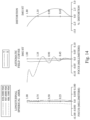
- Fig. 14 shows spherical aberration curves, astigmatic field curves and a distortion curve of the imaging apparatus 7 according to the 7th embodiment.
- the imaging apparatus 7 includes an image capturing system lens assembly (its reference numeral is omitted) and an image sensor IS.
- the image capturing system lens assembly includes, in order from an object side to an image side along an optical path, a first lens element E1, an aperture stop ST, a reflective element E7, a stop S1, a second lens element E2, a stop S2, a third lens element E3, a fourth lens element E4, a fifth lens element E5, a filter E6 and an image surface IMG, wherein the image sensor IS is disposed on the image surface IMG of the image capturing system lens assembly.
- the image capturing system lens assembly includes five lens elements (E1, E2, E3, E4, E5) without additional one or more lens elements inserted between the first lens element E1 and the fifth lens element E5.
- the first lens element E1 with positive refractive power has an object-side surface being concave in a paraxial region thereof and an image-side surface being convex in a paraxial region thereof.
- the first lens element E1 is made of a plastic material, and has the object-side surface and the image-side surface being both aspheric.
- the second lens element E2 with positive refractive power has an object-side surface being convex in a paraxial region thereof and an image-side surface being convex in a paraxial region thereof.
- the second lens element E2 is made of a plastic material, and has the object-side surface and the image-side surface being both aspheric. Furthermore, the object-side surface of the second lens element E2 includes one inflection point.
- the third lens element E3 with negative refractive power has an object-side surface being concave in a paraxial region thereof and an image-side surface being convex in a paraxial region thereof.
- the third lens element E3 is made of a plastic material, and has the object-side surface and the image-side surface being both aspheric. Furthermore, the object-side surface of the third lens element E3 includes one inflection point, and the image-side surface of the third lens element E3 includes three inflection points.
- the fourth lens element E4 with positive refractive power has an object-side surface being concave in a paraxial region thereof and an image-side surface being convex in a paraxial region thereof.
- the fourth lens element E4 is made of a plastic material, and has the object-side surface and the image-side surface being both aspheric. Furthermore, the object-side surface of the fourth lens element E4 includes one inflection point, and the image-side surface of the fourth lens element E4 includes one inflection point.
- the fifth lens element E5 with positive refractive power has an object-side surface being convex in a paraxial region thereof and an image-side surface being convex in a paraxial region thereof.
- the fifth lens element E5 is made of a plastic material, and has the object-side surface and the image-side surface being both aspheric. Furthermore, the object-side surface of the fifth lens element E5 includes two inflection points, and the image-side surface of the fifth lens element E5 includes two inflection points and one critical point.
- the reflective element E7 is a prism, which is made of glass material and disposed between the first lens element E1 and the second lens element E2.
- the filter E6 is made of a glass material, which is located between the fifth lens element E5 and the image surface IMG in order, and will not affect the focal length of the image capturing system lens assembly.
- Table 7A The detailed optical data of the 7th embodiment are shown in Table 7A and the aspheric surface data are shown in Table 7B below.
- Effective radius of Surface 6 (stop S1) is 0.890 mm. Effective radius of Surface 9 (stop S2) is 1.120 mm.
- Table 7B - Aspheric Coefficients Surface # 1 2 7 8 10 k -9.2798400E+00 -1.3934500E+01 9.7017700E-01 9.0357600E-01 9.2905300E+00
- A4 -3.4161952E-01 -2.4619081E-01 5.0490128E-02 1.7887831E-01 1.7409314E-01
- A6 7.5260165E-01 4.2523150E-01 -1.9902537E-02 -5.4224012E-01 -1.3422875E+00
- A8 -1.3416492E+00 1.3986590E+00 -1.3145575E-01 1.3676214E+00 -1.5795860E+00
- A10 1.8472559E+00 -1.5296014E+01 6.2793528E-01 -1.4517911
- the equation of the aspheric surface profiles of the aforementioned lens elements is the same as the equation of the 1st embodiment. Also, the definitions of these parameters shown in the following table are the same as those stated in the 1st embodiment with corresponding values for the 7th embodiment, so an explanation in this regard will not be provided again.
- Table 7C - 7th Embodiment f [mm] 1.98 (R1-R2)/(R1+R2) -0.11 Fno 2.20 (R3+R4)/(R3-R4) 0.10 HFOV [degrees] 43.3 (R5+R6)/(R5-R6) -2.49 ATmax/BL 2.57 (R7-R8)/(R7+R8) -0.09 ATmax/Y11 2.41 SL/TL 0.83 ATmax/f 1.11 T12/f 1.11 CT1/CTmax 1.00 T12/lmgH 1.22 (CT2+T23+CT3+T34+CT4+T45+CT5)/f 1.45 (T23+T34+T45)/ ⁇ AT 0.22 f/f12 1.33 T45/f 0.05 f/f2 1.02 TL/f 3.56 f/f3 -0.19 (TL-SL)/
- Fig. 13B is a schematic view of the imaging apparatus 7 with another reflective element E7 according to the 7th embodiment of the present disclosure.
- the difference between the Fig. 13B and Fig. 13A is that the reflective element E7 of Fig. 13B can fold the direction of the optical axis, so that the arrangement is favorable for adapting the electronic device with different requirements.
- Fig. 15A is a schematic view of an imaging apparatus 8 according to the 8th embodiment of the present disclosure.
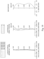
- Fig. 16 shows spherical aberration curves, astigmatic field curves and a distortion curve of the imaging apparatus 8 according to the 8th embodiment.
- the imaging apparatus 8 includes an image capturing system lens assembly (its reference numeral is omitted) and an image sensor IS.
- the image capturing system lens assembly includes, in order from an object side to an image side along an optical path, a first lens element E1, an aperture stop ST, a reflective element E7, a stop S1, a second lens element E2, a stop S2, a third lens element E3, a fourth lens element E4, a fifth lens element E5, a filter E6 and an image surface IMG, wherein the image sensor IS is disposed on the image surface IMG of the image capturing system lens assembly.
- the image capturing system lens assembly includes five lens elements (E1, E2, E3, E4, E5) without additional one or more lens elements inserted between the first lens element E1 and the fifth lens element E5.
- the first lens element E1 with positive refractive power has an object-side surface being concave in a paraxial region thereof and an image-side surface being convex in a paraxial region thereof.
- the first lens element E1 is made of a plastic material, and has the object-side surface and the image-side surface being both aspheric.
- the second lens element E2 with positive refractive power has an object-side surface being convex in a paraxial region thereof and an image-side surface being convex in a paraxial region thereof.
- the second lens element E2 is made of a plastic material, and has the object-side surface and the image-side surface being both aspheric. Furthermore, the object-side surface of the second lens element E2 includes one inflection point.
- the third lens element E3 with positive refractive power has an object-side surface being convex in a paraxial region thereof and an image-side surface being convex in a paraxial region thereof.
- the third lens element E3 is made of a plastic material, and has the object-side surface and the image-side surface being both aspheric. Furthermore, the object-side surface of the third lens element E3 includes three inflection points, and the image-side surface of the third lens element E3 includes three inflection points.
- the fourth lens element E4 with positive refractive power has an object-side surface being concave in a paraxial region thereof and an image-side surface being convex in a paraxial region thereof.
- the fourth lens element E4 is made of a plastic material, and has the object-side surface and the image-side surface being both aspheric. Furthermore, the object-side surface of the fourth lens element E4 includes one inflection point, and the image-side surface of the fourth lens element E4 includes one inflection point.
- the fifth lens element E5 with negative refractive power has an object-side surface being convex in a paraxial region thereof and an image-side surface being concave in a paraxial region thereof.
- the fifth lens element E5 is made of a plastic material, and has the object-side surface and the image-side surface being both aspheric. Furthermore, the object-side surface of the fifth lens element E5 includes two inflection points, and the image-side surface of the fifth lens element E5 includes three inflection points and two critical points.
- the reflective element E7 is a prism, which is made of glass material and disposed between the first lens element E1 and the second lens element E2.
- the filter E6 is made of a glass material, which is located between the fifth lens element E5 and the image surface IMG in order, and will not affect the focal length of the image capturing system lens assembly.
- Table 8A The detailed optical data of the 8th embodiment are shown in Table 8A and the aspheric surface data are shown in Table 8B below.
- Effective radius of Surface 6 (stop S1) is 0.945 mm. Effective radius of Surface 9 (stop S2) is 1.100 mm.
- Table 8B - Aspheric Coefficients Surface # 1 2 7 8 10 k -8.4369400E+00 -1.0679200E+01 9.3747800E-01 1.5554700E+00 -9.0000000E+01
- the equation of the aspheric surface profiles of the aforementioned lens elements is the same as the equation of the 1st embodiment. Also, the definitions of these parameters shown in the following table are the same as those stated in the 1st embodiment with corresponding values for the 8th embodiment, so an explanation in this regard will not be provided again.
- Table 8C - 8th Embodiment f[mm] 1.99 (R1-R2)/(R1+R2) -0.09 Fno 2.21 (R3+R4)/(R3-R4) 0.00 HFOV [degrees] 43.1 (R5+R6)/(R5-R6) -0.03 ATmax/BL 2.66 (R7-R8)/(R7+R8) -0.14 ATmax/Y11 2.47 SL/TL 0.83 ATmax/f 1.10 T12/f 1.10 CT1/CTmax 1.00 T12/lmgH 1.22 (CT2+T23+CT3+T34+CT4+T45+CT5)/f 1.49 (T23+T34+T45)/ ⁇ AT 0.16 f/f12 1.21 T45/f 0.04 f/f2 0.91 TL/f 3.59 f/f3 0.16 (TL-SL)/f 0.
- Fig. 15B is a schematic view of the imaging apparatus 8 with another reflective element E7 according to the 8th embodiment of the present disclosure.
- the difference between the Fig. 15B and Fig. 15A is that the reflective element E7 of Fig. 15B can fold the direction of the optical axis, so that the arrangement is favorable for adapting the electronic device with different requirements.
- Fig. 17A is a schematic view of an imaging apparatus 9 according to the 9th embodiment of the present disclosure.
- Fig. 18 shows spherical aberration curves, astigmatic field curves and a distortion curve of the imaging apparatus 9 according to the 9th embodiment.
- the imaging apparatus 9 includes an image capturing system lens assembly (its reference numeral is omitted) and an image sensor IS.
- the image capturing system lens assembly includes, in order from an object side to an image side along an optical path, a first lens element E1, an aperture stop ST, a reflective element E7, a stop S1, a second lens element E2, a stop S2, a third lens element E3, a fourth lens element E4, a fifth lens element E5, a filter E6 and an image surface IMG, wherein the image sensor IS is disposed on the image surface IMG of the image capturing system lens assembly.
- the image capturing system lens assembly includes five lens elements (E1, E2, E3, E4, E5) without additional one or more lens elements inserted between the first lens element E1 and the fifth lens element E5.
- the first lens element E1 with positive refractive power has an object-side surface being concave in a paraxial region thereof and an image-side surface being convex in a paraxial region thereof.
- the first lens element E1 is made of a plastic material, and has the object-side surface and the image-side surface being both aspheric.
- the second lens element E2 with positive refractive power has an object-side surface being convex in a paraxial region thereof and an image-side surface being convex in a paraxial region thereof.
- the second lens element E2 is made of a plastic material, and has the object-side surface and the image-side surface being both aspheric. Furthermore, the object-side surface of the second lens element E2 includes one inflection point, and the image-side surface of the second lens element E2 includes two inflection points.
- the third lens element E3 with negative refractive power has an object-side surface being concave in a paraxial region thereof and an image-side surface being concave in a paraxial region thereof.
- the third lens element E3 is made of a plastic material, and has the object-side surface and the image-side surface being both aspheric. Furthermore, the object-side surface of the third lens element E3 includes one inflection point.
- the fourth lens element E4 with positive refractive power has an object-side surface being concave in a paraxial region thereof and an image-side surface being convex in a paraxial region thereof.
- the fourth lens element E4 is made of a plastic material, and has the object-side surface and the image-side surface being both aspheric. Furthermore, the object-side surface of the fourth lens element E4 includes one inflection point, and the image-side surface of the fourth lens element E4 includes one inflection point.
- the fifth lens element E5 with negative refractive power has an object-side surface being concave in a paraxial region thereof and an image-side surface being concave in a paraxial region thereof.
- the fifth lens element E5 is made of a plastic material, and has the object-side surface and the image-side surface being both aspheric. Furthermore, the object-side surface of the fifth lens element E5 includes one inflection point, and the image-side surface of the fifth lens element E5 includes three inflection points and two critical points.
- the reflective element E7 is a prism, which is made of glass material and disposed between the first lens element E1 and the second lens element E2.
- the filter E6 is made of a glass material, which is located between the fifth lens element E5 and the image surface IMG in order, and will not affect the focal length of the image capturing system lens assembly.
- Table 9A The detailed optical data of the 9th embodiment are shown in Table 9A and the aspheric surface data are shown in Table 9B below.
- Effective radius of Surface 6 (stop S1) is 0.960 mm. Effective radius of Surface 9 (stop S2) is 1.100 mm.
- Table 9B - Aspheric Coefficients Surface # 1 2 7 8 10 k -7.8319500E+00 -9.3160300E+00 8.5683100E-01 1.4637900E+00 -9.0000000E+01
- A4 -4.2584496E-01 -2.9334832E-01 4.3318630E-02 -1.1911074E-01 -2.5985494E-01
- the equation of the aspheric surface profiles of the aforementioned lens elements is the same as the equation of the 1st embodiment. Also, the definitions of these parameters shown in the following table are the same as those stated in the 1st embodiment with corresponding values for the 9th embodiment, so an explanation in this regard will not be provided again.
- Fig. 17B is a schematic view of the imaging apparatus 9 with another reflective element E7 according to the 9th embodiment of the present disclosure.
- the difference between the Fig. 17B and Fig. 17A is that the reflective element E7 of Fig. 17B can fold the direction of the optical axis, so that the arrangement is favorable for adapting the electronic device with different requirements.
- Fig. 19A is a schematic view of an imaging apparatus 10 according to the 10th embodiment of the present disclosure.
- Fig. 20 shows spherical aberration curves, astigmatic field curves and a distortion curve of the imaging apparatus 10 according to the 10th embodiment.
- the imaging apparatus 10 includes an image capturing system lens assembly (its reference numeral is omitted) and an image sensor IS.
- the image capturing system lens assembly includes, in order from an object side to an image side along an optical path, a first lens element E1, an aperture stop ST, a reflective element E7, a stop S1, a second lens element E2, a stop S2, a third lens element E3, a fourth lens element E4, a fifth lens element E5, a filter E6 and an image surface IMG, wherein the image sensor IS is disposed on the image surface IMG of the image capturing system lens assembly.
- the image capturing system lens assembly includes five lens elements (E1, E2, E3, E4, E5) without additional one or more lens elements inserted between the first lens element E1 and the fifth lens element E5.
- the first lens element E1 with positive refractive power has an object-side surface being concave in a paraxial region thereof and an image-side surface being convex in a paraxial region thereof.
- the first lens element E1 is made of a glass material, and has the object-side surface and the image-side surface being both aspheric.
- the second lens element E2 with positive refractive power has an object-side surface being convex in a paraxial region thereof and an image-side surface being convex in a paraxial region thereof.
- the second lens element E2 is made of a plastic material, and has the object-side surface and the image-side surface being both aspheric. Furthermore, the object-side surface of the second lens element E2 includes one inflection point.
- the third lens element E3 with negative refractive power has an object-side surface being concave in a paraxial region thereof and an image-side surface being concave in a paraxial region thereof.
- the third lens element E3 is made of a plastic material, and has the object-side surface and the image-side surface being both aspheric. Furthermore, the object-side surface of the third lens element E3 includes one inflection point, and the image-side surface of the third lens element E3 includes four inflection points.
- the fourth lens element E4 with negative refractive power has an object-side surface being concave in a paraxial region thereof and an image-side surface being convex in a paraxial region thereof.
- the fourth lens element E4 is made of a plastic material, and has the object-side surface and the image-side surface being both aspheric. Furthermore, the object-side surface of the fourth lens element E4 includes three inflection points, and the image-side surface of the fourth lens element E4 includes one inflection point.
- the fifth lens element E5 with positive refractive power has an object-side surface being convex in a paraxial region thereof and an image-side surface being concave in a paraxial region thereof.
- the fifth lens element E5 is made of a plastic material, and has the object-side surface and the image-side surface being both aspheric. Furthermore, the object-side surface of the fifth lens element E5 includes one inflection point, and the image-side surface of the fifth lens element E5 includes one inflection point and one critical point.
- the reflective element E7 is a prism, which is made of glass material and disposed between the first lens element E1 and the second lens element E2.
- the filter E6 is made of a glass material, which is located between the fifth lens element E5 and the image surface IMG in order, and will not affect the focal length of the image capturing system lens assembly.
- Table 10A The detailed optical data of the 10th embodiment are shown in Table 10A and the aspheric surface data are shown in Table 10B below.
- Effective radius of Surface 6 (stop S1) is 0.875 mm. Effective radius of Surface 9 (stop S2) is 1.150 mm.
- Table 10B - Aspheric Coefficients Surface # 1 2 7 8 10 k 2.2123300E+00 1.8571300E+00 1.1193600E+00 2.7774600E+00 -8.9993600E+01
- A4 -8.0949195E-03 1.1712820E-01 7.4219290E-02 2.9843250E-01 -8.4938603E-01
- A10 1.0172328E+01 -9.9221035E+00 7.7961971E-01 2.7383357E
- the equation of the aspheric surface profiles of the aforementioned lens elements is the same as the equation of the 1st embodiment. Also, the definitions of these parameters shown in the following table are the same as those stated in the 1st embodiment with corresponding values for the 10th embodiment, so an explanation in this regard will not be provided again.
- Table 10C - 10th Embodiment f[mm] 2.19 (R1-R2)/(R1+R2) 0.09 Fno 2.32 (R3+R4)/(R3-R4) -0.05 HFOV [degrees] 39.2 (R5+R6)/(R5-R6) 0.73 ATmax/BL 2.95 (R7-R8)/(R7+R8) -0.53 ATmax/Y11 2.71 SL/TL 0.81 ATmax/f 1.03 T12/f 1.03 CT1/CTmax 1.00 T12/ImgH 1.25 (CT2+T23+CT3+T34+CT4+T45+CT5)/f 0.98 (T23+T34+T45)/ ⁇ AT 0.18 f/f12 1.31 T45/f 0.04 f/f2 0.93 TL/f 2.84 f/f3 -0.78 (TL-SL)/f 0.
- Fig. 19B is a schematic view of the imaging apparatus 10 with another reflective element E7 according to the 10th embodiment of the present disclosure.
- the difference between the Fig. 19B and Fig. 19A is that the reflective element E7 of Fig. 19B can fold the direction of the optical axis, so that the arrangement is favorable for adapting the electronic device with different requirements.
- Fig. 21A is a schematic view of an imaging apparatus 11 according to the 11th embodiment of the present disclosure.
- Fig. 22 shows spherical aberration curves, astigmatic field curves and a distortion curve of the imaging apparatus 11 according to the 11th embodiment.
- the imaging apparatus 11 includes an image capturing system lens assembly (its reference numeral is omitted) and an image sensor IS.
- the image capturing system lens assembly includes, in order from an object side to an image side along an optical path, a first lens element E1, an aperture stop ST, a reflective element E7, a stop S1, a second lens element E2, a stop S2, a third lens element E3, a fourth lens element E4, a fifth lens element E5, a filter E6 and an image surface IMG, wherein the image sensor IS is disposed on the image surface IMG of the image capturing system lens assembly.
- the image capturing system lens assembly includes five lens elements (E1, E2, E3, E4, E5) without additional one or more lens elements inserted between the first lens element E1 and the fifth lens element E5.
- the first lens element E1 with positive refractive power has an object-side surface being concave in a paraxial region thereof and an image-side surface being convex in a paraxial region thereof.
- the first lens element E1 is made of a plastic material, and has the object-side surface and the image-side surface being both aspheric. Furthermore, the object-side surface of the first lens element E1 includes one inflection point.
- the second lens element E2 with positive refractive power has an object-side surface being convex in a paraxial region thereof and an image-side surface being convex in a paraxial region thereof.
- the second lens element E2 is made of a plastic material, and has the object-side surface and the image-side surface being both aspheric. Furthermore, the object-side surface of the second lens element E2 includes one inflection point.
- the third lens element E3 with negative refractive power has an object-side surface being convex in a paraxial region thereof and an image-side surface being concave in a paraxial region thereof.
- the third lens element E3 is made of a plastic material, and has the object-side surface and the image-side surface being both aspheric. Furthermore, the object-side surface of the third lens element E3 includes two inflection points, and the image-side surface of the third lens element E3 includes two inflection points.
- the fourth lens element E4 with negative refractive power has an object-side surface being concave in a paraxial region thereof and an image-side surface being convex in a paraxial region thereof.
- the fourth lens element E4 is made of a plastic material, and has the object-side surface and the image-side surface being both aspheric. Furthermore, the object-side surface of the fourth lens element E4 includes one inflection point, and the image-side surface of the fourth lens element E4 includes one inflection point.
- the fifth lens element E5 with positive refractive power has an object-side surface being convex in a paraxial region thereof and an image-side surface being concave in a paraxial region thereof.
- the fifth lens element E5 is made of a plastic material, and has the object-side surface and the image-side surface being both aspheric. Furthermore, the object-side surface of the fifth lens element E5 includes one inflection point, and the image-side surface of the fifth lens element E5 includes one inflection point and one critical point.
- the reflective element E7 is a prism, which is made of glass material and disposed between the first lens element E1 and the second lens element E2.
- the filter E6 is made of a glass material, which is located between the fifth lens element E5 and the image surface IMG in order, and will not affect the focal length of the image capturing system lens assembly.
- Table 11A The detailed optical data of the 11th embodiment are shown in Table 11A and the aspheric surface data are shown in Table 11B below.
- Effective radius of Surface 6 (stop S1) is 0.883 mm. Effective radius of Surface 9 (stop S2) is 1.150 mm.
- Table 11B - Aspheric Coefficients Surface # 1 2 7 8 10 k 3.4227900E-01 6.1765500E-01 4.2985800E-02 2.9821700E-01 2.6209200E+01
- the equation of the aspheric surface profiles of the aforementioned lens elements is the same as the equation of the 1st embodiment. Also, the definitions of these parameters shown in the following table are the same as those stated in the 1st embodiment with corresponding values for the 11th embodiment, so an explanation in this regard will not be provided again.
- Fig. 21B is a schematic view of the imaging apparatus 11 with another reflective element E7 according to the 11th embodiment of the present disclosure.
- the difference between the Fig. 21B and Fig. 21A is that the reflective element E7 of Fig. 21B can fold the direction of the optical axis, so that the arrangement is favorable for adapting the electronic device with different requirements.
- Fig. 26 is a schematic view of an imaging apparatus 100 according to the 12th embodiment of the present disclosure.
- the imaging apparatus 100 of the 12th embodiment is a camera module
- the imaging apparatus 100 includes an imaging lens assembly 101, a driving apparatus 102 and an image sensor 103
- the imaging lens assembly 101 includes the image capturing system lens assembly of the present disclosure and a lens barrel (not shown in drawings) for carrying the image capturing system lens assembly.
- the imaging apparatus 100 can focus light from an imaged object via the imaging lens assembly 101, perform image focusing by the driving apparatus 102, and generate an image on the image sensor 103, and the imaging information can be transmitted.
- the driving apparatus 102 can be an auto-focus module, which can be driven by driving systems, such as voice coil motors (VCM), micro electro-mechanical systems (MEMS), piezoelectric systems, and shape memory alloys etc.
- VCM voice coil motors
- MEMS micro electro-mechanical systems
- the image capturing system lens assembly can obtain a favorable imaging position by the driving apparatus 102 so as to capture clear images when the imaged object is disposed at different object distances.
- the imaging apparatus 100 can include the image sensor 103 located on the image surface of the image capturing system lens assembly, such as CMOS and CCD, with superior photosensitivity and low noise. Thus, it is favorable for providing realistic images with high definition image quality thereof.
- the imaging apparatus 100 can further include an image stabilization module 104, which can be a kinetic energy sensor, such as an accelerometer, a gyro sensor, and a Hall Effect sensor.
- the image stabilization module 104 is a gyro sensor, but is not limited thereto. Therefore, the variation of different axial directions of the image capturing system lens assembly can adjusted so as to compensate the image blur generated by motion at the moment of exposure, and it is further favorable for enhancing the image. quality while photographing in motion and low light situation.
- advanced image compensation functions such as optical image stabilizations (OIS) and electronic image stabilizations (EIS) etc., can be provided.
- Fig. 27A is a schematic view of one side of an electronic device 200 according to the 13th embodiment of the present disclosure.
- Fig. 27B is a schematic view of another side of the electronic device 200 of Fig. 27A .
- Fig. 27C is a system schematic view of the electronic device 200 of Fig. 27A .
- the electronic device 200 according to the 13th embodiment is a smartphone, which include imaging apparatuses 100, 110, 120, 130, 140, a flash module 201, a focusing assisting module 202, an image signal processor (ISP) 203, a user interface 204 and an image software processor 205, wherein each of the imaging apparatuses 120, 130, 140 is a front camera.
- ISP image signal processor
- the electronic device 200 When the user captures images of an imaged object 206 via the user interface 204, the electronic device 200 focuses and generates an image via at least one of the imaging apparatuses 100, 110, 120, 130, 140, while compensating for low illumination via the flash module 201 when necessary. Then, the electronic device 200 quickly focuses on the imaged object 206 according to its object distance information provided by the focusing assisting module 202, and optimizes the image via the image signal processor 203 and the image software processor 205. Thus, the image quality can be further enhanced.
- the focusing assisting module 202 can adopt conventional infrared or laser for obtaining quick focusing, and the user interface 204 can utilize a touch screen or a physical button for capturing and processing the image with various functions of the image processing software.
- Each of the imaging apparatuses 100, 110, 120, 130, 140 according to the 13th embodiment can include the image capturing system lens assembly of the present disclosure, and can be the same or similar to the imaging apparatus 100 according to the aforementioned 12th embodiment, and will not describe again herein.
- the imaging apparatuses 100, 110 can be wide angle imaging apparatus and ultra-wide angle imaging apparatus, respectively.
- the imaging apparatuses 120, 130, 140 can be wide angle imaging apparatus, ultra-wide angle imaging apparatus and TOF (Time-Of-Flight) module, respectively, or can be others imaging apparatuses, which will not be limited thereto.
- the connecting relationships between each of the imaging apparatuses 110, 120, 130, 140 and other elements can be the same as the imaging apparatus 100 in Fig. 27C , or can be adaptively adjusted according to the type of the imaging apparatuses, which will not be shown and detailed descripted again.
- Fig. 28 is a schematic view of one side of an electronic device 300 according to the 14th embodiment of the present disclosure.
- the electronic device 300 is a smartphone, which include imaging apparatuses 310, 320, 330 and a flash module 301.
- the electronic device 300 according to the 14th embodiment can include the same or similar elements to that according to the 13th embodiment, and each of the imaging apparatuses 310, 320, 330 according to the 14th embodiment can have a configuration which is the same or similar to that according to the 13th embodiment, and will not describe again herein.
- each of the imaging apparatuses 310, 320, 330 can include the image capturing system lens assembly of the present disclosure, and can be the same or similar to the imaging apparatus 100 according to the aforementioned 12th embodiment, and will not describe again herein.
- the imaging apparatus 310 can be ultra-wide angle imaging apparatus
- the imaging apparatus 320 can be wide angle imaging apparatus
- the imaging apparatus 330 can be telephoto imaging apparatus (which can include light path folding element), or can be adaptively adjusted according to the type of the imaging apparatuses, which will not be limited to the arrangement.
- Fig. 29 is a schematic view of one side of an electronic device 400 according to the 15th embodiment of the present disclosure.
- the electronic device 400 is a smartphone, which include imaging apparatuses 410, 420, 430, 440, 450, 460, 470, 480, 490 and a flash module 401.
- the electronic device 400 according to the 15th embodiment can include the same or similar elements to that according to the 13th embodiment, and each of the imaging apparatuses 410, 420, 430, 440, 450, 460, 470, 480, 490 and the flash module 401 can have a configuration which is the same or similar to that according to the 13th embodiment, and will not describe again herein.
- each of the imaging apparatuses 410, 420, 430, 440, 450, 460, 470, 480, 490 can include the image capturing system lens assembly of the present disclosure, and can be the same or similar to the imaging apparatus 100 according to the aforementioned 12th embodiment, and will not describe again herein.
- each of the imaging apparatuses 410, 420 can be ultra-wide angle imaging apparatus
- each of the imaging apparatuses 430, 440 can be wide angle imaging apparatus
- each of the imaging apparatuses 450, 460 can be telephoto imaging apparatus
- each of the imaging apparatuses 470, 480 can be telephoto imaging apparatus (which can include light path folding element)
- the imaging apparatus 490 can be TOF module , or can be adaptively adjusted according to the type of the imaging apparatuses, which will not be limited to the arrangement.
- Fig. 30A is a schematic view of one side of an electronic device 500 according to the 16th embodiment of the present disclosure.
- Fig. 30B is a schematic view of another side of the electronic device 500 according to the 16th embodiment of Fig. 30A .
- the electronic device 500 is a smartphone, which include imaging apparatuses 510, 520, 530, 540 and a user interface 504.
- the electronic device 500 according to the 16th embodiment can include the same or similar elements to that according to the 13th embodiment, and each of the imaging apparatuses 510, 520, 530, 540 and the user interface 504 can have a configuration which is the same or similar to that according to the 13th embodiment, and will not describe again herein.
- the imaging apparatus 510 corresponds to a non-circular opening located on an outer side of the electronic device 500 for capturing the image
- the imaging apparatuses 520, 530, 540 can be telephoto imaging apparatus, wide angle imaging apparatus and ultra-wide angle imaging apparatus, respectively, or can be adaptively adjusted according to the type of the imaging apparatuses, which will not be limited to the arrangement.
Landscapes
- Physics & Mathematics (AREA)
- General Physics & Mathematics (AREA)
- Optics & Photonics (AREA)
- Lenses (AREA)
- Image Input (AREA)
- Studio Devices (AREA)
Claims (17)
- Linsenanordnung für ein Bildaufnahmesystem, umfassend fünf Linsenelemente (E1, E2, E3, E4, E5), wobei die fünf Linsenelemente (E1, E2, E3, E4, E5) in der Reihenfolge von einer Objektseite zu einer Bildseite entlang eines optischen Pfades wie folgt angeordnet sind:ein erstes Linsenelement (E1), ein zweites Linsenelement (E2), ein drittes Linsenelement (E3), ein viertes Linsenelement (E4) und ein fünftes Linsenelement (E5), wobei jedes der fünf Linsenelemente (E1, E2, E3, E4, E5) eine objektseitige Oberfläche zur Objektseite hin und eine bildseitige Oberfläche zur Bildseite hin aufweist;wobei mindestens eine der objektseitigen Oberfläche und der bildseitigen Oberfläche von mindestens einem des ersten Linsenelements (E1) bis zum fünften Linsenelement (E5) mindestens einen Wendepunkt aufweist; mindestens eines des ersten Linsenelements (E1) bis zum fünften Linsenelement (E5) aus Kunststoffmaterial besteht und sowohl eine objektseitige asphärische Oberfläche als auch eine bildseitige asphärische Oberfläche aufweist;wobei die Linsenanordnung für ein Bildaufnahmesystem ferner eine Aperturblende (ST) umfasst, ein axialer Abstand zwischen der Aperturblende (ST) und einer Bildfläche (IMG) SL ist, ein axialer Abstand zwischen der objektseitigen Oberfläche des ersten Linsenelements (E1) und der Bildfläche (IMG) TL ist, ein axialer Abstand zwischen dem ersten Linsenelement (E1) und dem zweiten Linsenelement (E2) T12 ist, ein axialer Abstand zwischen dem zweiten Linsenelement (E2) und dem dritten Linsenelement (E3) T23 ist, ein axialer Abstand zwischen dem dritten Linsenelement (E3) und dem vierten Linsenelement (E4) T34 ist, ein axialer Abstand zwischen dem vierten Linsenelement (E4) und dem fünften Linsenelement (E5) T45 ist, ein Maximum von T12, T23, T34, T45 ATmax ist, ein axialer Abstand zwischen der bildseitigen Oberfläche des fünften Linsenelements (E5) und der Bildfläche (IMG) BL ist, eine Brennweite der Linsenanordnung für ein Bildaufnahmesystem f ist, eine Brennweite des zweiten Linsenelements (E2) f2 ist, eine Brennweite des dritten Linsenelements (E3) f3 ist, ein Krümmungsradius der objektseitigen Oberfläche des ersten Linsenelements (E1) R1 ist und die folgenden Bedingungen erfüllt sind:


 dadurch gekennzeichnet, dassdie folgenden Bedingungen erfüllt sind:


- Linsenanordnung für ein Bildaufnahmesystem nach Anspruch 1, wobei der axiale Abstand zwischen der Aperturblende (ST) und der Bildfläche (IMG) SL ist, der axiale Abstand zwischen der objektseitigen Oberfläche des ersten Linsenelements (E1) und der Bildfläche (IMG) TL ist, die Brennweite der Linsenanordnung für ein Bildaufnahmesystem f ist und die folgende Bedingung erfüllt ist:

- Linsenanordnung für ein Bildaufnahmesystem nach einem der Ansprüche 1-2, wobei der axiale Abstand zwischen dem ersten Linsenelement (E1) und dem zweiten Linsenelement (E2) T12 ist, der axiale Abstand zwischen dem zweiten Linsenelement (E2) und dem dritten Linsenelement (E3) T23 ist, der axiale Abstand zwischen dem dritten Linsenelement (E3) und dem vierten Linsenelement (E4) T34 ist, der axiale Abstand zwischen dem vierten Linsenelement (E4) und dem fünften Linsenelement (E5) T45 ist, das Maximum von T12, T23, T34, T45 ATmax ist, die Brennweite der Linsenanordnung für ein Bildaufnahmesystem f ist und die folgende Bedingung erfüllt ist:

- Linsenanordnung für ein Bildaufnahmesystem nach einem der Ansprüche 1-3, wobei der axiale Abstand zwischen dem zweiten Linsenelement (E2) und dem dritten Linsenelement (E3) T23 ist, der axiale Abstand zwischen dem dritten Linsenelement (E3) und dem vierten Linsenelement (E4) T34 ist, der axiale Abstand zwischen dem vierten Linsenelement (E4) und dem fünften Linsenelement (E5) T45 ist, die Summe aller axialen Abstände zwischen benachbarten Linsenelementen der Linsenanordnung für ein Bildaufnahmesystem ΣAT ist und die folgende Bedingung erfüllt ist:

- Linsenanordnung für ein Bildaufnahmesystem nach einem der Ansprüche 1-4, wobei ein Krümmungsradius der objektseitigen Oberfläche des zweiten Linsenelements (E2) R3 ist, ein Krümmungsradius der bildseitigen Oberfläche des zweiten Linsenelements (E2) R4 ist und die folgende Bedingung erfüllt ist:

- Linsenanordnung für ein Bildaufnahmesystem nach einem der Ansprüche 1-5, wobei der axiale Abstand zwischen dem ersten Linsenelement (E1) und dem zweiten Linsenelement (E2) T12 ist, eine maximale Bildhöhe der Linsenanordnung für ein Bildaufnahmesystem ImgH ist und die folgende Bedingung erfüllt ist:

- Linsenanordnung für ein Bildaufnahmesystem nach einem der Ansprüche 1-6, ferner umfassend:
ein reflektierendes Element (E7), das zwischen dem ersten Linsenelement (E1) und dem fünften Linsenelement (E5) angeordnet ist. - Bildgebungsvorrichtung (1), dadurch gekennzeichnet, dass sie Folgendes umfasst:die Linsenanordnung für ein Bildaufnahmesystem nach einem der Ansprüche 1-7; undeinen Bildsensor (IS), der auf der Bildfläche (IMG) der Linsenanordnung für ein Bildaufnahmesystem angeordnet ist.
- Elektronische Vorrichtung (200), dadurch gekennzeichnet, dass sie Folgendes umfasst:
die Bildgebungsvorrichtung (100, 110, 120, 130, 140) nach Anspruch 8. - Linsenanordnung für ein Bildaufnahmesystem, umfassend fünf Linsenelemente (E1, E2, E3, E4, E5), wobei die fünf Linsenelemente (E1, E2, E3, E4, E5) in der Reihenfolge von einer Objektseite zu einer Bildseite entlang eines optischen Pfades wie folgt angeordnet sind:ein erstes Linsenelement (E1), ein zweites Linsenelement (E2), ein drittes Linsenelement (E3), ein viertes Linsenelement (E4) und ein fünftes Linsenelement (E5), wobei jedes der fünf Linsenelemente (E1, E2, E3, E4, E5) eine objektseitige Oberfläche zur Objektseite hin und eine bildseitige Oberfläche zur Bildseite hin aufweist;wobeimindestens eine der objektseitigen Oberfläche und der bildseitigen Oberfläche von mindestens einem des ersten Linsenelements (E1) bis zum fünften Linsenelement (E5) mindestens einen Wendepunkt (IP) aufweist;wobei die Linsenanordnung für ein Bildaufnahmesystem ferner eine Aperturblende (ST) umfasst, ein axialer Abstand zwischen der Aperturblende (ST) und einer Bildfläche (IMG) SL ist, ein axialer Abstand zwischen der objektseitigen Oberfläche des ersten Linsenelements (E1) und der Bildfläche (IMG) TL ist, ein axialer Abstand zwischen dem ersten Linsenelement (E1) und dem zweiten Linsenelement (E2) T12 ist, ein axialer Abstand zwischen dem zweiten Linsenelement (E2) und dem dritten Linsenelement (E3) T23 ist, ein axialer Abstand zwischen dem dritten Linsenelement (E3) und dem vierten Linsenelement (E4) T34 ist, ein axialer Abstand zwischen dem vierten Linsenelement (E4) und dem fünften Linsenelement (E5) T45 ist, ein Maximum von T12, T23, T34, T45 ATmax ist, ein axialer Abstand zwischen der bildseitigen Oberfläche des fünften Linsenelements (E5) und der Bildfläche (IMG) BL ist, eine Brennweite der Linsenanordnung für ein Bildaufnahmesystems f ist, eine Brennweite des zweiten Linsenelements (E2) f2 ist und die folgenden Bedingungen erfüllt sind:


 dadurch gekennzeichnet, dassdie objektseitige Oberfläche des zweiten Linsenelements in einem paraxialen Bereich davon konvex ist; und dass die folgenden Bedingungen erfüllt sind:


- Linsenanordnung für ein Bildaufnahmesystem nach Anspruch 10, wobei ein Brechungsindex des dritten Linsenelements (E3) N3 ist, ein Brechungsindex des fünften Linsenelements (E5) N5 ist und die folgende Bedingung erfüllt ist:

- Linsenanordnung für ein Bildaufnahmesystem nach einem der Ansprüche 10-11, wobei eine f-Zahl der Linsenanordnung für ein Bildaufnahmesystem Fno ist, ein maximaler Abstand zwischen einem optisch wirksamen Bereich der objektseitigen Oberfläche des ersten Linsenelements (E1) und einer optischen Achse Y11 ist, der axiale Abstand zwischen dem ersten Linsenelement (E1) und dem zweiten Linsenelement (E2) T12 ist, der axiale Abstand zwischen dem zweiten Linsenelement (E2) und dem dritten Linsenelement (E3) T23 ist, der axiale Abstand zwischen dem dritten Linsenelement (E3) und dem vierten Linsenelement (E4) T34 ist, der axiale Abstand zwischen dem vierten Linsenelement (E4) und dem fünften Linsenelement (E5) T45 ist, das Maximum von T12, T23, T34, T45 ATmax ist und die folgenden Bedingungen erfüllt sind:


- Linsenanordnung für ein Bildaufnahmesystem nach einem der Ansprüche 10-12, wobei ein maximaler Abstand zwischen einem optisch wirksamen Bereich der objektseitigen Oberfläche des ersten Linsenelements (E1) und einer optischen Achse Y11 ist, eine maximale Bildhöhe der Linsenanordnung für ein Bildaufnahmesystem ImgH ist und die folgende Bedingung erfüllt ist:

- Linsenanordnung für ein Bildaufnahmesystem nach einem der Ansprüche 10-13, wobei eine zentrale Dicke des ersten Linsenelements (E1) CT1 ist, eine zentrale Dicke des zweiten Linsenelements (E2) CT2 ist, eine zentrale Dicke des dritten Linsenelements (E3) CT3 ist, eine zentrale Dicke des vierten Linsenelements (E4) CT4, eine zentrale Dicke des fünften Linsenelements (E5) CT5 ist, ein Maximum von CT1, CT2, CT3, CT4, CT5 CTmax ist und die folgende Bedingung erfüllt ist:

- Linsenanordnung für ein Bildaufnahmesystem nach einem der Ansprüche 10-14, wobei die Brennweite der Linsenanordnung für ein Bildaufnahmesystem f ist, ein Krümmungsradius der bildseitigen Oberfläche des zweiten Linsenelements (E2) R4 ist, der axiale Abstand zwischen dem vierten Linsenelement (E4) und dem fünften Linsenelement (E5) T45 ist und die folgenden Bedingungen erfüllt sind:


- Linsenanordnung für ein Bildaufnahmesystem nach einem der Ansprüche 10-15, wobei die Abbe-Zahl eines der Linsenelemente Vi ist und der Brechungsindex des Linsenelements Ni ist und mindestens eines der fünf Linsenelemente die folgende Bedingung erfüllt:

- Linsenanordnung für ein Bildaufnahmesystem nach einem der Ansprüche 10-16, wobei es eine relative Verschiebung zwischen dem ersten Linsenelement (E1) und dem fünften Linsenelement (ES) gibt.
Applications Claiming Priority (1)
| Application Number | Priority Date | Filing Date | Title |
|---|---|---|---|
| TW110141420A TWI797816B (zh) | 2021-11-05 | 2021-11-05 | 取像系統鏡組、取像裝置及電子裝置 |
Publications (2)
| Publication Number | Publication Date |
|---|---|
| EP4177656A1 EP4177656A1 (de) | 2023-05-10 |
| EP4177656B1 true EP4177656B1 (de) | 2024-08-21 |
Family
ID=84044623
Family Applications (1)
| Application Number | Title | Priority Date | Filing Date |
|---|---|---|---|
| EP22204681.5A Active EP4177656B1 (de) | 2021-11-05 | 2022-10-31 | Linsenanordnung für ein bilderfassungssystem, abbildungsvorrichtung und elektronisches gerät |
Country Status (4)
| Country | Link |
|---|---|
| US (1) | US12422650B2 (de) |
| EP (1) | EP4177656B1 (de) |
| CN (1) | CN116088132A (de) |
| TW (1) | TWI797816B (de) |
Families Citing this family (2)
| Publication number | Priority date | Publication date | Assignee | Title |
|---|---|---|---|---|
| KR20220082525A (ko) * | 2020-12-10 | 2022-06-17 | 엘지이노텍 주식회사 | 광학계 및 이를 포함하는 카메라 모듈 |
| JP2023183790A (ja) * | 2022-06-16 | 2023-12-28 | キヤノン株式会社 | 光学系、撮像装置、車載システム、および移動装置 |
Family Cites Families (46)
| Publication number | Priority date | Publication date | Assignee | Title |
|---|---|---|---|---|
| JP2900378B2 (ja) | 1988-10-18 | 1999-06-02 | 株式会社ニコン | ケプラー式ズームファインダー光学系 |
| JPH03145614A (ja) | 1989-11-01 | 1991-06-20 | Olympus Optical Co Ltd | 内視鏡対物レンズ |
| US5251069A (en) | 1989-12-28 | 1993-10-05 | Asahi Kogaku Kogyo K.K. | Imaging lens system |
| US5270863A (en) | 1990-04-05 | 1993-12-14 | Olympus Optical Co., Ltd. | Zoom lens system |
| US5278698A (en) | 1990-07-06 | 1994-01-11 | Asahi Kogaku Kogyo Kabushiki Kaisha | Magnifying projecting lens |
| JPH0545582A (ja) | 1990-07-06 | 1993-02-23 | Asahi Optical Co Ltd | 拡大投影レンズ |
| US5305147A (en) | 1990-08-20 | 1994-04-19 | Olympus Optical Co., Ltd. | Eyepiece lens system for endoscopes |
| JPH10274739A (ja) * | 1997-03-28 | 1998-10-13 | Canon Inc | ズームレンズ |
| JP2003344761A (ja) | 2002-05-23 | 2003-12-03 | Casio Comput Co Ltd | 撮影レンズ |
| JP2007333966A (ja) * | 2006-06-14 | 2007-12-27 | Sony Corp | 撮像レンズ及び撮像装置 |
| JP5102069B2 (ja) * | 2008-02-29 | 2012-12-19 | 富士フイルム株式会社 | 投写レンズおよびこれを用いた投写型表示装置 |
| JP2010079252A (ja) | 2008-09-01 | 2010-04-08 | Fujinon Corp | 小型投写レンズおよびこれを用いた投写型表示装置 |
| JP5199148B2 (ja) | 2009-02-24 | 2013-05-15 | 富士フイルム株式会社 | 投写レンズおよびこれを用いた投写型表示装置 |
| JP2011085744A (ja) | 2009-10-15 | 2011-04-28 | Topcon Corp | 小型プロジェクタ用投射レンズ |
| JP5442515B2 (ja) | 2010-03-30 | 2014-03-12 | 富士フイルム株式会社 | 投写用レンズおよびこれを用いた投写型表示装置 |
| JP5480089B2 (ja) * | 2010-09-29 | 2014-04-23 | 富士フイルム株式会社 | 投写用レンズおよび投写型表示装置 |
| WO2012105181A1 (ja) | 2011-01-31 | 2012-08-09 | 富士フイルム株式会社 | 投写レンズおよび投写型表示装置 |
| CN103076665A (zh) | 2011-10-26 | 2013-05-01 | 鸿富锦精密工业(深圳)有限公司 | 取像镜头 |
| KR101422910B1 (ko) * | 2012-04-30 | 2014-07-23 | 삼성전기주식회사 | 카메라용 광학계 |
| JP5226888B2 (ja) * | 2012-06-19 | 2013-07-03 | オリンパス株式会社 | 折り曲げ結像光学系 |
| JP2015034885A (ja) | 2013-08-09 | 2015-02-19 | キヤノン株式会社 | 単焦点レンズ及びそれを有する撮像装置 |
| TWM476934U (en) * | 2013-11-15 | 2014-04-21 | Glory Science Co Ltd | Imaging optical lens assembly |
| CN204009194U (zh) | 2014-07-15 | 2014-12-10 | 浙江舜宇光学有限公司 | 3d交互式镜头 |
| CN104297906A (zh) | 2014-10-20 | 2015-01-21 | 宁波舜宇车载光学技术有限公司 | 一种光学镜头 |
| WO2016062230A1 (zh) | 2014-10-20 | 2016-04-28 | 宁波舜宇车载光学技术有限公司 | 光学镜头 |
| JP2016114648A (ja) | 2014-12-11 | 2016-06-23 | 株式会社タムロン | 結像光学系 |
| CN105301739B (zh) | 2015-11-06 | 2017-12-22 | 舜宇光学(中山)有限公司 | 一种日夜两用监控定焦镜头 |
| US9696523B1 (en) * | 2015-12-28 | 2017-07-04 | Newmax Technology Co., Ltd. | Optical imaging lens |
| EP3531181B1 (de) | 2016-10-19 | 2023-04-05 | Panasonic Intellectual Property Management Co., Ltd. | Bildgebungslinsensystem und kamera |
| CN106970456B (zh) * | 2017-01-20 | 2020-01-14 | 玉晶光电(厦门)有限公司 | 光学镜片组 |
| CN110308544B (zh) | 2018-03-27 | 2021-10-22 | 宁波舜宇车载光学技术有限公司 | 光学镜头 |
| CN209070187U (zh) | 2018-10-21 | 2019-07-05 | 辽宁中蓝电子科技有限公司 | 一种带棱镜结构的摄像透镜组 |
| CN110187476A (zh) | 2019-07-08 | 2019-08-30 | 东莞市宇瞳光学科技股份有限公司 | 一种玻塑混合的定焦镜头 |
| CN210323548U (zh) | 2019-08-26 | 2020-04-14 | 南昌欧菲精密光学制品有限公司 | 光学系统、镜头模组和电子设备 |
| WO2021035493A1 (zh) | 2019-08-26 | 2021-03-04 | 南昌欧菲精密光学制品有限公司 | 光学系统、镜头模组和电子设备 |
| TWI704387B (zh) | 2020-03-05 | 2020-09-11 | 信泰光學(深圳)有限公司 | 成像鏡頭(四十四) |
| TWI687730B (zh) | 2019-10-31 | 2020-03-11 | 大陸商信泰光學(深圳)有限公司 | 成像鏡頭(四十一) |
| US11668902B2 (en) | 2019-09-27 | 2023-06-06 | Sintai Optical (Shenzhen) Co., Ltd. | Lens assembly |
| CN112748518B (zh) | 2019-10-31 | 2022-08-23 | 亚洲光学股份有限公司 | 成像镜头 |
| CN113132583B (zh) | 2019-12-31 | 2023-01-20 | 华为技术有限公司 | 光学镜头、摄像头模组和终端 |
| CN111045196B (zh) | 2020-01-02 | 2024-12-13 | 东莞市美光达光学科技有限公司 | 一种大视场、高像素光学系统及采用该光学系统的手机摄像头模组 |
| TWM598410U (zh) * | 2020-01-30 | 2020-07-11 | 先進光電科技股份有限公司 | 光學成像系統 |
| CN111443469B (zh) | 2020-05-20 | 2025-01-28 | 威海世高光电子有限公司 | 超短物距成像镜头及电子设备 |
| TWI746031B (zh) | 2020-06-29 | 2021-11-11 | 大陸商信泰光學(深圳)有限公司 | 成像鏡頭(四十五) |
| US12411317B2 (en) | 2021-02-26 | 2025-09-09 | Sintai Optical (Shenzhen) Co., Ltd. | Lens assembly |
| CN113433655A (zh) | 2021-06-10 | 2021-09-24 | 中国电子科技集团公司第十一研究所 | 一种三波段共孔径光学系统 |
-
2021
- 2021-11-05 TW TW110141420A patent/TWI797816B/zh active
-
2022
- 2022-02-25 CN CN202210191088.4A patent/CN116088132A/zh active Pending
- 2022-06-14 US US17/839,779 patent/US12422650B2/en active Active
- 2022-10-31 EP EP22204681.5A patent/EP4177656B1/de active Active
Also Published As
| Publication number | Publication date |
|---|---|
| US20230141883A1 (en) | 2023-05-11 |
| CN116088132A (zh) | 2023-05-09 |
| EP4177656A1 (de) | 2023-05-10 |
| TWI797816B (zh) | 2023-04-01 |
| TW202319802A (zh) | 2023-05-16 |
| US12422650B2 (en) | 2025-09-23 |
| BR102022022485A2 (pt) | 2023-09-26 |
Similar Documents
| Publication | Publication Date | Title |
|---|---|---|
| US12216255B2 (en) | Photographing optical lens assembly including eight lenses of +−+−−++−, +−++−++−, ++++−++− or +−+−+−+−refractive powers, imaging apparatus and electronic device | |
| US11249282B2 (en) | Photographing optical lens assembly, imaging apparatus and electronic device | |
| US11982875B2 (en) | Image capturing lens assembly, imaging apparatus and electronic device | |
| EP3961281B1 (de) | Optische bildlinsenanordnung, bildaufnahmeeinheit und elektronische vorrichtung | |
| EP3995878B1 (de) | Optisches bildaufnahmesystem, bildaufnahmeeinheit und elektronische vorrichtung | |
| US12411314B2 (en) | Image capturing optical lens system, imaging apparatus and electronic device | |
| EP4148478B1 (de) | Optische abbildungssystemanordnung, abbildungsgerät und elektronische vorrichtung | |
| US11899172B2 (en) | Imaging optical lens assembly including five lenses +−++−, −++−, −−++−, +−+++, +++−+, +−+−+, +−+−−, or −++−+ of refractive powers, imaging apparatus and electronic device | |
| US12044829B2 (en) | Image capturing lens assembly, imaging apparatus and electronic device | |
| EP4001985A2 (de) | Optisches abbildungslinsensystem, bildaufnahmeeinheit und elektronische vorrichtung | |
| US20250004250A1 (en) | Image capturing system lens assembly, imaging apparatus and electronic device | |
| US11487089B2 (en) | Image capturing optical lens assembly including five lenses of +−++− or +−−+− refractive powers, imaging apparatus and electronic device | |
| US20250004254A1 (en) | Image lens assembly, imaging apparatus and electronic device | |
| EP4279974A2 (de) | Linsenanordnung für bildgebungssystem, bildgebungsvorrichtung und elektronische vorrichtung | |
| US11966031B2 (en) | Image lens assembly, zoom imaging apparatus and electronic device | |
| EP4177656B1 (de) | Linsenanordnung für ein bilderfassungssystem, abbildungsvorrichtung und elektronisches gerät | |
| EP4345524A2 (de) | Linsenanordnung für bildgebungssystem, bildgebungsvorrichtung und elektronische vorrichtung | |
| EP4224234B1 (de) | Linsenanordnung für ein optisches bildgebungssystem, bildgebungsvorrichtung und elektronische vorrichtung | |
| EP4071534B1 (de) | Optische bildgebungslinsenanordnung, bildaufnahmeeinheit und elektronische vorrichtung | |
| US20240264410A1 (en) | Photographing system lens assembly, imaging apparatus and electronic device | |
| EP4293407B1 (de) | Linsenanordnung für bildgebungssystem, bildgebungsvorrichtung und elektronische vorrichtung | |
| US12000991B2 (en) | Optical image capturing lens assembly, imaging apparatus and electronic device | |
| US20260072251A1 (en) | Imaging optical lens system, imaging apparatus and electronic device |
Legal Events
| Date | Code | Title | Description |
|---|---|---|---|
| PUAI | Public reference made under article 153(3) epc to a published international application that has entered the european phase |
Free format text: ORIGINAL CODE: 0009012 |
|
| STAA | Information on the status of an ep patent application or granted ep patent |
Free format text: STATUS: REQUEST FOR EXAMINATION WAS MADE |
|
| 17P | Request for examination filed |
Effective date: 20221031 |
|
| AK | Designated contracting states |
Kind code of ref document: A1 Designated state(s): AL AT BE BG CH CY CZ DE DK EE ES FI FR GB GR HR HU IE IS IT LI LT LU LV MC ME MK MT NL NO PL PT RO RS SE SI SK SM TR |
|
| GRAP | Despatch of communication of intention to grant a patent |
Free format text: ORIGINAL CODE: EPIDOSNIGR1 |
|
| STAA | Information on the status of an ep patent application or granted ep patent |
Free format text: STATUS: GRANT OF PATENT IS INTENDED |
|
| INTG | Intention to grant announced |
Effective date: 20240320 |
|
| GRAS | Grant fee paid |
Free format text: ORIGINAL CODE: EPIDOSNIGR3 |
|
| GRAA | (expected) grant |
Free format text: ORIGINAL CODE: 0009210 |
|
| STAA | Information on the status of an ep patent application or granted ep patent |
Free format text: STATUS: THE PATENT HAS BEEN GRANTED |
|
| AK | Designated contracting states |
Kind code of ref document: B1 Designated state(s): AL AT BE BG CH CY CZ DE DK EE ES FI FR GB GR HR HU IE IS IT LI LT LU LV MC ME MK MT NL NO PL PT RO RS SE SI SK SM TR |
|
| REG | Reference to a national code |
Ref country code: GB Ref legal event code: FG4D |
|
| REG | Reference to a national code |
Ref country code: CH Ref legal event code: EP |
|
| REG | Reference to a national code |
Ref country code: DE Ref legal event code: R096 Ref document number: 602022005474 Country of ref document: DE |
|
| REG | Reference to a national code |
Ref country code: IE Ref legal event code: FG4D |
|
| REG | Reference to a national code |
Ref country code: NL Ref legal event code: FP |
|
| P01 | Opt-out of the competence of the unified patent court (upc) registered |
Free format text: CASE NUMBER: APP_48303/2024 Effective date: 20240822 |
|
| REG | Reference to a national code |
Ref country code: LT Ref legal event code: MG9D |
|
| PG25 | Lapsed in a contracting state [announced via postgrant information from national office to epo] |
Ref country code: NO Free format text: LAPSE BECAUSE OF FAILURE TO SUBMIT A TRANSLATION OF THE DESCRIPTION OR TO PAY THE FEE WITHIN THE PRESCRIBED TIME-LIMIT Effective date: 20241121 |
|
| REG | Reference to a national code |
Ref country code: AT Ref legal event code: MK05 Ref document number: 1716058 Country of ref document: AT Kind code of ref document: T Effective date: 20240821 |
|
| PG25 | Lapsed in a contracting state [announced via postgrant information from national office to epo] |
Ref country code: FI Free format text: LAPSE BECAUSE OF FAILURE TO SUBMIT A TRANSLATION OF THE DESCRIPTION OR TO PAY THE FEE WITHIN THE PRESCRIBED TIME-LIMIT Effective date: 20240821 Ref country code: PL Free format text: LAPSE BECAUSE OF FAILURE TO SUBMIT A TRANSLATION OF THE DESCRIPTION OR TO PAY THE FEE WITHIN THE PRESCRIBED TIME-LIMIT Effective date: 20240821 Ref country code: GR Free format text: LAPSE BECAUSE OF FAILURE TO SUBMIT A TRANSLATION OF THE DESCRIPTION OR TO PAY THE FEE WITHIN THE PRESCRIBED TIME-LIMIT Effective date: 20241122 Ref country code: PT Free format text: LAPSE BECAUSE OF FAILURE TO SUBMIT A TRANSLATION OF THE DESCRIPTION OR TO PAY THE FEE WITHIN THE PRESCRIBED TIME-LIMIT Effective date: 20241223 |
|
| PG25 | Lapsed in a contracting state [announced via postgrant information from national office to epo] |
Ref country code: BG Free format text: LAPSE BECAUSE OF FAILURE TO SUBMIT A TRANSLATION OF THE DESCRIPTION OR TO PAY THE FEE WITHIN THE PRESCRIBED TIME-LIMIT Effective date: 20240821 |
|
| PG25 | Lapsed in a contracting state [announced via postgrant information from national office to epo] |
Ref country code: LV Free format text: LAPSE BECAUSE OF FAILURE TO SUBMIT A TRANSLATION OF THE DESCRIPTION OR TO PAY THE FEE WITHIN THE PRESCRIBED TIME-LIMIT Effective date: 20240821 |
|
| PG25 | Lapsed in a contracting state [announced via postgrant information from national office to epo] |
Ref country code: AT Free format text: LAPSE BECAUSE OF FAILURE TO SUBMIT A TRANSLATION OF THE DESCRIPTION OR TO PAY THE FEE WITHIN THE PRESCRIBED TIME-LIMIT Effective date: 20240821 Ref country code: IS Free format text: LAPSE BECAUSE OF FAILURE TO SUBMIT A TRANSLATION OF THE DESCRIPTION OR TO PAY THE FEE WITHIN THE PRESCRIBED TIME-LIMIT Effective date: 20241221 |
|
| PG25 | Lapsed in a contracting state [announced via postgrant information from national office to epo] |
Ref country code: HR Free format text: LAPSE BECAUSE OF FAILURE TO SUBMIT A TRANSLATION OF THE DESCRIPTION OR TO PAY THE FEE WITHIN THE PRESCRIBED TIME-LIMIT Effective date: 20240821 |
|
| PG25 | Lapsed in a contracting state [announced via postgrant information from national office to epo] |
Ref country code: RS Free format text: LAPSE BECAUSE OF FAILURE TO SUBMIT A TRANSLATION OF THE DESCRIPTION OR TO PAY THE FEE WITHIN THE PRESCRIBED TIME-LIMIT Effective date: 20241121 Ref country code: ES Free format text: LAPSE BECAUSE OF FAILURE TO SUBMIT A TRANSLATION OF THE DESCRIPTION OR TO PAY THE FEE WITHIN THE PRESCRIBED TIME-LIMIT Effective date: 20240821 |
|
| PG25 | Lapsed in a contracting state [announced via postgrant information from national office to epo] |
Ref country code: RS Free format text: LAPSE BECAUSE OF FAILURE TO SUBMIT A TRANSLATION OF THE DESCRIPTION OR TO PAY THE FEE WITHIN THE PRESCRIBED TIME-LIMIT Effective date: 20241121 Ref country code: PT Free format text: LAPSE BECAUSE OF FAILURE TO SUBMIT A TRANSLATION OF THE DESCRIPTION OR TO PAY THE FEE WITHIN THE PRESCRIBED TIME-LIMIT Effective date: 20241223 Ref country code: PL Free format text: LAPSE BECAUSE OF FAILURE TO SUBMIT A TRANSLATION OF THE DESCRIPTION OR TO PAY THE FEE WITHIN THE PRESCRIBED TIME-LIMIT Effective date: 20240821 Ref country code: NO Free format text: LAPSE BECAUSE OF FAILURE TO SUBMIT A TRANSLATION OF THE DESCRIPTION OR TO PAY THE FEE WITHIN THE PRESCRIBED TIME-LIMIT Effective date: 20241121 Ref country code: LV Free format text: LAPSE BECAUSE OF FAILURE TO SUBMIT A TRANSLATION OF THE DESCRIPTION OR TO PAY THE FEE WITHIN THE PRESCRIBED TIME-LIMIT Effective date: 20240821 Ref country code: IS Free format text: LAPSE BECAUSE OF FAILURE TO SUBMIT A TRANSLATION OF THE DESCRIPTION OR TO PAY THE FEE WITHIN THE PRESCRIBED TIME-LIMIT Effective date: 20241221 Ref country code: HR Free format text: LAPSE BECAUSE OF FAILURE TO SUBMIT A TRANSLATION OF THE DESCRIPTION OR TO PAY THE FEE WITHIN THE PRESCRIBED TIME-LIMIT Effective date: 20240821 Ref country code: GR Free format text: LAPSE BECAUSE OF FAILURE TO SUBMIT A TRANSLATION OF THE DESCRIPTION OR TO PAY THE FEE WITHIN THE PRESCRIBED TIME-LIMIT Effective date: 20241122 Ref country code: FI Free format text: LAPSE BECAUSE OF FAILURE TO SUBMIT A TRANSLATION OF THE DESCRIPTION OR TO PAY THE FEE WITHIN THE PRESCRIBED TIME-LIMIT Effective date: 20240821 Ref country code: ES Free format text: LAPSE BECAUSE OF FAILURE TO SUBMIT A TRANSLATION OF THE DESCRIPTION OR TO PAY THE FEE WITHIN THE PRESCRIBED TIME-LIMIT Effective date: 20240821 Ref country code: BG Free format text: LAPSE BECAUSE OF FAILURE TO SUBMIT A TRANSLATION OF THE DESCRIPTION OR TO PAY THE FEE WITHIN THE PRESCRIBED TIME-LIMIT Effective date: 20240821 Ref country code: AT Free format text: LAPSE BECAUSE OF FAILURE TO SUBMIT A TRANSLATION OF THE DESCRIPTION OR TO PAY THE FEE WITHIN THE PRESCRIBED TIME-LIMIT Effective date: 20240821 |
|
| PG25 | Lapsed in a contracting state [announced via postgrant information from national office to epo] |
Ref country code: SM Free format text: LAPSE BECAUSE OF FAILURE TO SUBMIT A TRANSLATION OF THE DESCRIPTION OR TO PAY THE FEE WITHIN THE PRESCRIBED TIME-LIMIT Effective date: 20240821 Ref country code: RO Free format text: LAPSE BECAUSE OF FAILURE TO SUBMIT A TRANSLATION OF THE DESCRIPTION OR TO PAY THE FEE WITHIN THE PRESCRIBED TIME-LIMIT Effective date: 20240821 Ref country code: DK Free format text: LAPSE BECAUSE OF FAILURE TO SUBMIT A TRANSLATION OF THE DESCRIPTION OR TO PAY THE FEE WITHIN THE PRESCRIBED TIME-LIMIT Effective date: 20240821 |
|
| PG25 | Lapsed in a contracting state [announced via postgrant information from national office to epo] |
Ref country code: EE Free format text: LAPSE BECAUSE OF FAILURE TO SUBMIT A TRANSLATION OF THE DESCRIPTION OR TO PAY THE FEE WITHIN THE PRESCRIBED TIME-LIMIT Effective date: 20240821 |
|
| PG25 | Lapsed in a contracting state [announced via postgrant information from national office to epo] |
Ref country code: CZ Free format text: LAPSE BECAUSE OF FAILURE TO SUBMIT A TRANSLATION OF THE DESCRIPTION OR TO PAY THE FEE WITHIN THE PRESCRIBED TIME-LIMIT Effective date: 20240821 |
|
| PG25 | Lapsed in a contracting state [announced via postgrant information from national office to epo] |
Ref country code: IT Free format text: LAPSE BECAUSE OF FAILURE TO SUBMIT A TRANSLATION OF THE DESCRIPTION OR TO PAY THE FEE WITHIN THE PRESCRIBED TIME-LIMIT Effective date: 20240821 Ref country code: SK Free format text: LAPSE BECAUSE OF FAILURE TO SUBMIT A TRANSLATION OF THE DESCRIPTION OR TO PAY THE FEE WITHIN THE PRESCRIBED TIME-LIMIT Effective date: 20240821 |
|
| REG | Reference to a national code |
Ref country code: DE Ref legal event code: R097 Ref document number: 602022005474 Country of ref document: DE |
|
| PLBE | No opposition filed within time limit |
Free format text: ORIGINAL CODE: 0009261 |
|
| STAA | Information on the status of an ep patent application or granted ep patent |
Free format text: STATUS: NO OPPOSITION FILED WITHIN TIME LIMIT |
|
| PG25 | Lapsed in a contracting state [announced via postgrant information from national office to epo] |
Ref country code: MC Free format text: LAPSE BECAUSE OF FAILURE TO SUBMIT A TRANSLATION OF THE DESCRIPTION OR TO PAY THE FEE WITHIN THE PRESCRIBED TIME-LIMIT Effective date: 20240821 |
|
| PG25 | Lapsed in a contracting state [announced via postgrant information from national office to epo] |
Ref country code: LU Free format text: LAPSE BECAUSE OF NON-PAYMENT OF DUE FEES Effective date: 20241031 Ref country code: BE Free format text: LAPSE BECAUSE OF NON-PAYMENT OF DUE FEES Effective date: 20241031 |
|
| PG25 | Lapsed in a contracting state [announced via postgrant information from national office to epo] |
Ref country code: FR Free format text: LAPSE BECAUSE OF NON-PAYMENT OF DUE FEES Effective date: 20241031 |
|
| 26N | No opposition filed |
Effective date: 20250522 |
|
| REG | Reference to a national code |
Ref country code: BE Ref legal event code: MM Effective date: 20241031 |
|
| PG25 | Lapsed in a contracting state [announced via postgrant information from national office to epo] |
Ref country code: SE Free format text: LAPSE BECAUSE OF FAILURE TO SUBMIT A TRANSLATION OF THE DESCRIPTION OR TO PAY THE FEE WITHIN THE PRESCRIBED TIME-LIMIT Effective date: 20240821 |
|
| PG25 | Lapsed in a contracting state [announced via postgrant information from national office to epo] |
Ref country code: IE Free format text: LAPSE BECAUSE OF NON-PAYMENT OF DUE FEES Effective date: 20241031 |
|
| PGFP | Annual fee paid to national office [announced via postgrant information from national office to epo] |
Ref country code: NL Payment date: 20251021 Year of fee payment: 4 |
|
| PGFP | Annual fee paid to national office [announced via postgrant information from national office to epo] |
Ref country code: DE Payment date: 20251028 Year of fee payment: 4 |
|
| PG25 | Lapsed in a contracting state [announced via postgrant information from national office to epo] |
Ref country code: HU Free format text: LAPSE BECAUSE OF FAILURE TO SUBMIT A TRANSLATION OF THE DESCRIPTION OR TO PAY THE FEE WITHIN THE PRESCRIBED TIME-LIMIT; INVALID AB INITIO Effective date: 20221031 |
|
| PG25 | Lapsed in a contracting state [announced via postgrant information from national office to epo] |
Ref country code: CY Free format text: LAPSE BECAUSE OF FAILURE TO SUBMIT A TRANSLATION OF THE DESCRIPTION OR TO PAY THE FEE WITHIN THE PRESCRIBED TIME-LIMIT; INVALID AB INITIO Effective date: 20221031 |