EP4177717A1 - Faltbare elektronische vorrichtung zur steuerung der bildschirmrotation und betriebsverfahren dafür - Google Patents
Faltbare elektronische vorrichtung zur steuerung der bildschirmrotation und betriebsverfahren dafür Download PDFInfo
- Publication number
- EP4177717A1 EP4177717A1 EP21854226.4A EP21854226A EP4177717A1 EP 4177717 A1 EP4177717 A1 EP 4177717A1 EP 21854226 A EP21854226 A EP 21854226A EP 4177717 A1 EP4177717 A1 EP 4177717A1
- Authority
- EP
- European Patent Office
- Prior art keywords
- display
- sensor
- housing
- electronic device
- content
- Prior art date
- Legal status (The legal status is an assumption and is not a legal conclusion. Google has not performed a legal analysis and makes no representation as to the accuracy of the status listed.)
- Granted
Links
Images









Classifications
-
- G—PHYSICS
- G06—COMPUTING OR CALCULATING; COUNTING
- G06F—ELECTRIC DIGITAL DATA PROCESSING
- G06F3/00—Input arrangements for transferring data to be processed into a form capable of being handled by the computer; Output arrangements for transferring data from processing unit to output unit, e.g. interface arrangements
- G06F3/14—Digital output to display device ; Cooperation and interconnection of the display device with other functional units
- G06F3/1423—Digital output to display device ; Cooperation and interconnection of the display device with other functional units controlling a plurality of local displays, e.g. CRT and flat panel display
- G06F3/1431—Digital output to display device ; Cooperation and interconnection of the display device with other functional units controlling a plurality of local displays, e.g. CRT and flat panel display using a single graphics controller
-
- G—PHYSICS
- G06—COMPUTING OR CALCULATING; COUNTING
- G06F—ELECTRIC DIGITAL DATA PROCESSING
- G06F3/00—Input arrangements for transferring data to be processed into a form capable of being handled by the computer; Output arrangements for transferring data from processing unit to output unit, e.g. interface arrangements
- G06F3/01—Input arrangements or combined input and output arrangements for interaction between user and computer
- G06F3/03—Arrangements for converting the position or the displacement of a member into a coded form
- G06F3/033—Pointing devices displaced or positioned by the user, e.g. mice, trackballs, pens or joysticks; Accessories therefor
- G06F3/038—Control and interface arrangements therefor, e.g. drivers or device-embedded control circuitry
-
- G—PHYSICS
- G06—COMPUTING OR CALCULATING; COUNTING
- G06F—ELECTRIC DIGITAL DATA PROCESSING
- G06F3/00—Input arrangements for transferring data to be processed into a form capable of being handled by the computer; Output arrangements for transferring data from processing unit to output unit, e.g. interface arrangements
- G06F3/14—Digital output to display device ; Cooperation and interconnection of the display device with other functional units
- G06F3/1423—Digital output to display device ; Cooperation and interconnection of the display device with other functional units controlling a plurality of local displays, e.g. CRT and flat panel display
- G06F3/1446—Digital output to display device ; Cooperation and interconnection of the display device with other functional units controlling a plurality of local displays, e.g. CRT and flat panel display display composed of modules, e.g. video walls
-
- G—PHYSICS
- G06—COMPUTING OR CALCULATING; COUNTING
- G06F—ELECTRIC DIGITAL DATA PROCESSING
- G06F1/00—Details not covered by groups G06F3/00 - G06F13/00 and G06F21/00
- G06F1/16—Constructional details or arrangements
- G06F1/1613—Constructional details or arrangements for portable computers
- G06F1/1615—Constructional details or arrangements for portable computers with several enclosures having relative motions, each enclosure supporting at least one I/O or computing function
- G06F1/1616—Constructional details or arrangements for portable computers with several enclosures having relative motions, each enclosure supporting at least one I/O or computing function with folding flat displays, e.g. laptop computers or notebooks having a clamshell configuration, with body parts pivoting to an open position around an axis parallel to the plane they define in closed position
- G06F1/1618—Constructional details or arrangements for portable computers with several enclosures having relative motions, each enclosure supporting at least one I/O or computing function with folding flat displays, e.g. laptop computers or notebooks having a clamshell configuration, with body parts pivoting to an open position around an axis parallel to the plane they define in closed position the display being foldable up to the back of the other housing with a single degree of freedom, e.g. by 360° rotation over the axis defined by the rear edge of the base enclosure
-
- G—PHYSICS
- G06—COMPUTING OR CALCULATING; COUNTING
- G06F—ELECTRIC DIGITAL DATA PROCESSING
- G06F1/00—Details not covered by groups G06F3/00 - G06F13/00 and G06F21/00
- G06F1/16—Constructional details or arrangements
- G06F1/1613—Constructional details or arrangements for portable computers
- G06F1/1633—Constructional details or arrangements of portable computers not specific to the type of enclosures covered by groups G06F1/1615 - G06F1/1626
- G06F1/1637—Details related to the display arrangement, including those related to the mounting of the display in the housing
- G06F1/1641—Details related to the display arrangement, including those related to the mounting of the display in the housing the display being formed by a plurality of foldable display components
-
- G—PHYSICS
- G06—COMPUTING OR CALCULATING; COUNTING
- G06F—ELECTRIC DIGITAL DATA PROCESSING
- G06F1/00—Details not covered by groups G06F3/00 - G06F13/00 and G06F21/00
- G06F1/16—Constructional details or arrangements
- G06F1/1613—Constructional details or arrangements for portable computers
- G06F1/1633—Constructional details or arrangements of portable computers not specific to the type of enclosures covered by groups G06F1/1615 - G06F1/1626
- G06F1/1637—Details related to the display arrangement, including those related to the mounting of the display in the housing
- G06F1/1647—Details related to the display arrangement, including those related to the mounting of the display in the housing including at least an additional display
-
- G—PHYSICS
- G06—COMPUTING OR CALCULATING; COUNTING
- G06F—ELECTRIC DIGITAL DATA PROCESSING
- G06F1/00—Details not covered by groups G06F3/00 - G06F13/00 and G06F21/00
- G06F1/16—Constructional details or arrangements
- G06F1/1613—Constructional details or arrangements for portable computers
- G06F1/1633—Constructional details or arrangements of portable computers not specific to the type of enclosures covered by groups G06F1/1615 - G06F1/1626
- G06F1/1637—Details related to the display arrangement, including those related to the mounting of the display in the housing
- G06F1/1652—Details related to the display arrangement, including those related to the mounting of the display in the housing the display being flexible, e.g. mimicking a sheet of paper, or rollable
-
- G—PHYSICS
- G06—COMPUTING OR CALCULATING; COUNTING
- G06F—ELECTRIC DIGITAL DATA PROCESSING
- G06F1/00—Details not covered by groups G06F3/00 - G06F13/00 and G06F21/00
- G06F1/16—Constructional details or arrangements
- G06F1/1613—Constructional details or arrangements for portable computers
- G06F1/1633—Constructional details or arrangements of portable computers not specific to the type of enclosures covered by groups G06F1/1615 - G06F1/1626
- G06F1/1675—Miscellaneous details related to the relative movement between the different enclosures or enclosure parts
- G06F1/1677—Miscellaneous details related to the relative movement between the different enclosures or enclosure parts for detecting open or closed state or particular intermediate positions assumed by movable parts of the enclosure, e.g. detection of display lid position with respect to main body in a laptop, detection of opening of the cover of battery compartment
-
- G—PHYSICS
- G06—COMPUTING OR CALCULATING; COUNTING
- G06F—ELECTRIC DIGITAL DATA PROCESSING
- G06F1/00—Details not covered by groups G06F3/00 - G06F13/00 and G06F21/00
- G06F1/16—Constructional details or arrangements
- G06F1/1613—Constructional details or arrangements for portable computers
- G06F1/1633—Constructional details or arrangements of portable computers not specific to the type of enclosures covered by groups G06F1/1615 - G06F1/1626
- G06F1/1675—Miscellaneous details related to the relative movement between the different enclosures or enclosure parts
- G06F1/1681—Details related solely to hinges
-
- G—PHYSICS
- G06—COMPUTING OR CALCULATING; COUNTING
- G06F—ELECTRIC DIGITAL DATA PROCESSING
- G06F1/00—Details not covered by groups G06F3/00 - G06F13/00 and G06F21/00
- G06F1/26—Power supply means, e.g. regulation thereof
- G06F1/32—Means for saving power
- G06F1/3203—Power management, i.e. event-based initiation of a power-saving mode
- G06F1/3206—Monitoring of events, devices or parameters that trigger a change in power modality
-
- G—PHYSICS
- G06—COMPUTING OR CALCULATING; COUNTING
- G06F—ELECTRIC DIGITAL DATA PROCESSING
- G06F1/00—Details not covered by groups G06F3/00 - G06F13/00 and G06F21/00
- G06F1/26—Power supply means, e.g. regulation thereof
- G06F1/32—Means for saving power
- G06F1/3203—Power management, i.e. event-based initiation of a power-saving mode
- G06F1/3234—Power saving characterised by the action undertaken
- G06F1/325—Power saving in peripheral device
-
- G—PHYSICS
- G06—COMPUTING OR CALCULATING; COUNTING
- G06F—ELECTRIC DIGITAL DATA PROCESSING
- G06F1/00—Details not covered by groups G06F3/00 - G06F13/00 and G06F21/00
- G06F1/26—Power supply means, e.g. regulation thereof
- G06F1/32—Means for saving power
- G06F1/3203—Power management, i.e. event-based initiation of a power-saving mode
- G06F1/3234—Power saving characterised by the action undertaken
- G06F1/325—Power saving in peripheral device
- G06F1/3265—Power saving in display device
-
- G—PHYSICS
- G06—COMPUTING OR CALCULATING; COUNTING
- G06F—ELECTRIC DIGITAL DATA PROCESSING
- G06F3/00—Input arrangements for transferring data to be processed into a form capable of being handled by the computer; Output arrangements for transferring data from processing unit to output unit, e.g. interface arrangements
- G06F3/01—Input arrangements or combined input and output arrangements for interaction between user and computer
- G06F3/03—Arrangements for converting the position or the displacement of a member into a coded form
- G06F3/033—Pointing devices displaced or positioned by the user, e.g. mice, trackballs, pens or joysticks; Accessories therefor
- G06F3/0346—Pointing devices displaced or positioned by the user, e.g. mice, trackballs, pens or joysticks; Accessories therefor with detection of the device orientation or free movement in a three-dimensional [3D] space, e.g. 3D mice, 6-DOF [six degrees of freedom] pointers using gyroscopes, accelerometers or tilt-sensors
-
- G—PHYSICS
- G06—COMPUTING OR CALCULATING; COUNTING
- G06F—ELECTRIC DIGITAL DATA PROCESSING
- G06F3/00—Input arrangements for transferring data to be processed into a form capable of being handled by the computer; Output arrangements for transferring data from processing unit to output unit, e.g. interface arrangements
- G06F3/01—Input arrangements or combined input and output arrangements for interaction between user and computer
- G06F3/048—Interaction techniques based on graphical user interfaces [GUI]
- G06F3/0484—Interaction techniques based on graphical user interfaces [GUI] for the control of specific functions or operations, e.g. selecting or manipulating an object, an image or a displayed text element, setting a parameter value or selecting a range
-
- G—PHYSICS
- G06—COMPUTING OR CALCULATING; COUNTING
- G06F—ELECTRIC DIGITAL DATA PROCESSING
- G06F3/00—Input arrangements for transferring data to be processed into a form capable of being handled by the computer; Output arrangements for transferring data from processing unit to output unit, e.g. interface arrangements
- G06F3/01—Input arrangements or combined input and output arrangements for interaction between user and computer
- G06F3/048—Interaction techniques based on graphical user interfaces [GUI]
- G06F3/0487—Interaction techniques based on graphical user interfaces [GUI] using specific features provided by the input device, e.g. functions controlled by the rotation of a mouse with dual sensing arrangements, or of the nature of the input device, e.g. tap gestures based on pressure sensed by a digitiser
- G06F3/0488—Interaction techniques based on graphical user interfaces [GUI] using specific features provided by the input device, e.g. functions controlled by the rotation of a mouse with dual sensing arrangements, or of the nature of the input device, e.g. tap gestures based on pressure sensed by a digitiser using a touch-screen or digitiser, e.g. input of commands through traced gestures
-
- G—PHYSICS
- G06—COMPUTING OR CALCULATING; COUNTING
- G06F—ELECTRIC DIGITAL DATA PROCESSING
- G06F3/00—Input arrangements for transferring data to be processed into a form capable of being handled by the computer; Output arrangements for transferring data from processing unit to output unit, e.g. interface arrangements
- G06F3/01—Input arrangements or combined input and output arrangements for interaction between user and computer
- G06F3/048—Interaction techniques based on graphical user interfaces [GUI]
- G06F3/0487—Interaction techniques based on graphical user interfaces [GUI] using specific features provided by the input device, e.g. functions controlled by the rotation of a mouse with dual sensing arrangements, or of the nature of the input device, e.g. tap gestures based on pressure sensed by a digitiser
- G06F3/0488—Interaction techniques based on graphical user interfaces [GUI] using specific features provided by the input device, e.g. functions controlled by the rotation of a mouse with dual sensing arrangements, or of the nature of the input device, e.g. tap gestures based on pressure sensed by a digitiser using a touch-screen or digitiser, e.g. input of commands through traced gestures
- G06F3/04886—Interaction techniques based on graphical user interfaces [GUI] using specific features provided by the input device, e.g. functions controlled by the rotation of a mouse with dual sensing arrangements, or of the nature of the input device, e.g. tap gestures based on pressure sensed by a digitiser using a touch-screen or digitiser, e.g. input of commands through traced gestures by partitioning the display area of the touch-screen or the surface of the digitising tablet into independently controllable areas, e.g. virtual keyboards or menus
-
- G—PHYSICS
- G06—COMPUTING OR CALCULATING; COUNTING
- G06F—ELECTRIC DIGITAL DATA PROCESSING
- G06F3/00—Input arrangements for transferring data to be processed into a form capable of being handled by the computer; Output arrangements for transferring data from processing unit to output unit, e.g. interface arrangements
- G06F3/14—Digital output to display device ; Cooperation and interconnection of the display device with other functional units
- G06F3/147—Digital output to display device ; Cooperation and interconnection of the display device with other functional units using display panels
-
- G—PHYSICS
- G09—EDUCATION; CRYPTOGRAPHY; DISPLAY; ADVERTISING; SEALS
- G09G—ARRANGEMENTS OR CIRCUITS FOR CONTROL OF INDICATING DEVICES USING STATIC MEANS TO PRESENT VARIABLE INFORMATION
- G09G3/00—Control arrangements or circuits, of interest only in connection with visual indicators other than cathode-ray tubes
- G09G3/03—Control arrangements or circuits, of interest only in connection with visual indicators other than cathode-ray tubes specially adapted for displays having non-planar surfaces, e.g. curved displays
- G09G3/035—Control arrangements or circuits, of interest only in connection with visual indicators other than cathode-ray tubes specially adapted for displays having non-planar surfaces, e.g. curved displays for flexible display surfaces
-
- G—PHYSICS
- G09—EDUCATION; CRYPTOGRAPHY; DISPLAY; ADVERTISING; SEALS
- G09G—ARRANGEMENTS OR CIRCUITS FOR CONTROL OF INDICATING DEVICES USING STATIC MEANS TO PRESENT VARIABLE INFORMATION
- G09G5/00—Control arrangements or circuits for visual indicators common to cathode-ray tube indicators and other visual indicators
-
- H—ELECTRICITY
- H04—ELECTRIC COMMUNICATION TECHNIQUE
- H04M—TELEPHONIC COMMUNICATION
- H04M1/00—Substation equipment, e.g. for use by subscribers
- H04M1/02—Constructional features of telephone sets
- H04M1/0202—Portable telephone sets, e.g. cordless phones, mobile phones or bar type handsets
- H04M1/0206—Portable telephones comprising a plurality of mechanically joined movable body parts, e.g. hinged housings
- H04M1/0208—Portable telephones comprising a plurality of mechanically joined movable body parts, e.g. hinged housings characterized by the relative motions of the body parts
- H04M1/0214—Foldable telephones, i.e. with body parts pivoting to an open position around an axis parallel to the plane they define in closed position
-
- H—ELECTRICITY
- H04—ELECTRIC COMMUNICATION TECHNIQUE
- H04M—TELEPHONIC COMMUNICATION
- H04M1/00—Substation equipment, e.g. for use by subscribers
- H04M1/02—Constructional features of telephone sets
- H04M1/0202—Portable telephone sets, e.g. cordless phones, mobile phones or bar type handsets
- H04M1/0206—Portable telephones comprising a plurality of mechanically joined movable body parts, e.g. hinged housings
- H04M1/0208—Portable telephones comprising a plurality of mechanically joined movable body parts, e.g. hinged housings characterized by the relative motions of the body parts
- H04M1/0214—Foldable telephones, i.e. with body parts pivoting to an open position around an axis parallel to the plane they define in closed position
- H04M1/0216—Foldable in one direction, i.e. using a one degree of freedom hinge
-
- H—ELECTRICITY
- H04—ELECTRIC COMMUNICATION TECHNIQUE
- H04M—TELEPHONIC COMMUNICATION
- H04M1/00—Substation equipment, e.g. for use by subscribers
- H04M1/02—Constructional features of telephone sets
- H04M1/0202—Portable telephone sets, e.g. cordless phones, mobile phones or bar type handsets
- H04M1/0206—Portable telephones comprising a plurality of mechanically joined movable body parts, e.g. hinged housings
- H04M1/0241—Portable telephones comprising a plurality of mechanically joined movable body parts, e.g. hinged housings using relative motion of the body parts to change the operational status of the telephone set, e.g. switching on/off, answering incoming call
- H04M1/0243—Portable telephones comprising a plurality of mechanically joined movable body parts, e.g. hinged housings using relative motion of the body parts to change the operational status of the telephone set, e.g. switching on/off, answering incoming call using the relative angle between housings
-
- H—ELECTRICITY
- H04—ELECTRIC COMMUNICATION TECHNIQUE
- H04M—TELEPHONIC COMMUNICATION
- H04M1/00—Substation equipment, e.g. for use by subscribers
- H04M1/02—Constructional features of telephone sets
- H04M1/0202—Portable telephone sets, e.g. cordless phones, mobile phones or bar type handsets
- H04M1/026—Details of the structure or mounting of specific components
- H04M1/0266—Details of the structure or mounting of specific components for a display module assembly
- H04M1/0268—Details of the structure or mounting of specific components for a display module assembly including a flexible display panel
-
- G—PHYSICS
- G06—COMPUTING OR CALCULATING; COUNTING
- G06F—ELECTRIC DIGITAL DATA PROCESSING
- G06F2200/00—Indexing scheme relating to G06F1/04 - G06F1/32
- G06F2200/16—Indexing scheme relating to G06F1/16 - G06F1/18
- G06F2200/161—Indexing scheme relating to constructional details of the monitor
- G06F2200/1614—Image rotation following screen orientation, e.g. switching from landscape to portrait mode
-
- G—PHYSICS
- G06—COMPUTING OR CALCULATING; COUNTING
- G06F—ELECTRIC DIGITAL DATA PROCESSING
- G06F2200/00—Indexing scheme relating to G06F1/04 - G06F1/32
- G06F2200/16—Indexing scheme relating to G06F1/16 - G06F1/18
- G06F2200/163—Indexing scheme relating to constructional details of the computer
- G06F2200/1637—Sensing arrangement for detection of housing movement or orientation, e.g. for controlling scrolling or cursor movement on the display of an handheld computer
-
- G—PHYSICS
- G06—COMPUTING OR CALCULATING; COUNTING
- G06F—ELECTRIC DIGITAL DATA PROCESSING
- G06F2203/00—Indexing scheme relating to G06F3/00 - G06F3/048
- G06F2203/048—Indexing scheme relating to G06F3/048
- G06F2203/04803—Split screen, i.e. subdividing the display area or the window area into separate subareas
-
- G—PHYSICS
- G09—EDUCATION; CRYPTOGRAPHY; DISPLAY; ADVERTISING; SEALS
- G09G—ARRANGEMENTS OR CIRCUITS FOR CONTROL OF INDICATING DEVICES USING STATIC MEANS TO PRESENT VARIABLE INFORMATION
- G09G2340/00—Aspects of display data processing
- G09G2340/14—Solving problems related to the presentation of information to be displayed
-
- G—PHYSICS
- G09—EDUCATION; CRYPTOGRAPHY; DISPLAY; ADVERTISING; SEALS
- G09G—ARRANGEMENTS OR CIRCUITS FOR CONTROL OF INDICATING DEVICES USING STATIC MEANS TO PRESENT VARIABLE INFORMATION
- G09G2380/00—Specific applications
- G09G2380/02—Flexible displays
-
- H—ELECTRICITY
- H04—ELECTRIC COMMUNICATION TECHNIQUE
- H04M—TELEPHONIC COMMUNICATION
- H04M1/00—Substation equipment, e.g. for use by subscribers
- H04M1/72—Mobile telephones; Cordless telephones, i.e. devices for establishing wireless links to base stations without route selection
- H04M1/724—User interfaces specially adapted for cordless or mobile telephones
- H04M1/72448—User interfaces specially adapted for cordless or mobile telephones with means for adapting the functionality of the device according to specific conditions
- H04M1/72454—User interfaces specially adapted for cordless or mobile telephones with means for adapting the functionality of the device according to specific conditions according to context-related or environment-related conditions
-
- H—ELECTRICITY
- H04—ELECTRIC COMMUNICATION TECHNIQUE
- H04M—TELEPHONIC COMMUNICATION
- H04M2250/00—Details of telephonic subscriber devices
- H04M2250/12—Details of telephonic subscriber devices including a sensor for measuring a physical value, e.g. temperature or motion
Definitions
- a foldable electronic device may operate in an in-folding, out-folding, in/out-folding, sliding, and/or rolling manner through rotation of a first housing and a second housing with respect to each other via a hinge module.
- Various embodiments of the disclosure provide a device and a method for controlling screen rotation in a foldable electronic device.
- an operation method of an electronic device may include: identifying, by a first sensor and a second sensor, a folding angle between a first housing and a second housing, the first sensor being disposed in a first space of the first housing which is connected to a hinge module and includes a first surface, a second surface facing a direction opposite to the first surface, and a first lateral surface surrounding the first space between the first surface and the second surface, the second sensor being disposed in a second space of the second housing which is connected to the hinge module so as to be foldable with respect to the first housing and, in an unfolded state, includes a third surface facing the same direction as the first surface, a fourth surface facing a direction opposite to the third surface, and a second lateral surface surrounding the second space between the third surface and the fourth surface; when the folding angle between the first housing and the second housing satisfies a designated first range, from among a first display disposed from at least a part of the first surface to at least a part of the third surface, and a
- the processor 120 may execute, for example, software (e.g., a program 140) to control at least one other component (e.g., a hardware or software component) of the electronic device 101 coupled with the processor 120, and may perform various data processing or computation.
- the processor 120 may store a command or data received from another component (e.g., the sensor module 176 or the communication module 190) in volatile memory 132, process the command or the data stored in the volatile memory 132, and store resulting data in non-volatile memory 134.
- the processor 120 may include a main processor 121 (e.g., a central processing unit (CPU) or an application processor (AP)), or an auxiliary processor 123 (e.g., a graphics processing unit (GPU), a neural processing unit (NPU), an image signal processor (ISP), a sensor hub processor, or a communication processor (CP)) that is operable independently from, or in conjunction with, the main processor 121.
- a main processor 121 e.g., a central processing unit (CPU) or an application processor (AP)
- auxiliary processor 123 e.g., a graphics processing unit (GPU), a neural processing unit (NPU), an image signal processor (ISP), a sensor hub processor, or a communication processor (CP)
- the main processor 121 may be adapted to consume less power than the main processor 121, or to be specific to a specified function.
- the auxiliary processor 123 may be implemented as separate from, or as part of the main processor 121.
- the auxiliary processor 123 may control at least some of functions or states related to at least one component (e.g., the display module 160, the sensor module 176, or the communication module 190) among the components of the electronic device 101, instead of the main processor 121 while the main processor 121 is in an inactive (e.g., sleep) state, or together with the main processor 121 while the main processor 121 is in an active state (e.g., executing an application).
- the auxiliary processor 123 e.g., an image signal processor or a communication processor
- the artificial neural network may be a deep neural network (DNN), a convolutional neural network (CNN), a recurrent neural network (RNN), a restricted boltzmann machine (RBM), a deep belief network (DBN), a bidirectional recurrent deep neural network (BRDNN), deep Q-network or a combination of two or more thereof but is not limited thereto.
- the artificial intelligence model may, additionally or alternatively, include a software structure other than the hardware structure.
- the input module 150 may receive a command or data to be used by another component (e.g., the processor 120) of the electronic device 101, from the outside (e.g., a user) of the electronic device 101.
- the input module 150 may include, for example, a microphone, a mouse, a keyboard, a key (e.g., a button), or a digital pen (e.g., a stylus pen).
- the sound output module 155 may output sound signals to the outside of the electronic device 101.
- the sound output module 155 may include, for example, a speaker or a receiver.
- the speaker may be used for general purposes, such as playing multimedia or playing record.
- the receiver may be used for receiving incoming calls. According to an embodiment, the receiver may be implemented as separate from, or as part of the speaker.
- the camera module 180 may capture a still image or moving images.
- the camera module 180 may include one or more lenses, image sensors, image signal processors, or flashes.
- the communication module 190 may support establishing a direct (e.g., wired) communication channel or a wireless communication channel between the electronic device 101 and the external electronic device (e.g., the electronic device 102, the electronic device 104, or the server 108) and performing communication via the established communication channel.
- the communication module 190 may include one or more communication processors that are operable independently from the processor 120 (e.g., the application processor (AP)) and supports a direct (e.g., wired) communication or a wireless communication.
- AP application processor
- a corresponding one of these communication modules may communicate with the external electronic device via the first network 198 (e.g., a short-range communication network, such as Bluetooth TM , wireless-fidelity (Wi-Fi) direct, or infrared data association (IrDA)) or the second network 199 (e.g., a long-range communication network, such as a legacy cellular network, a 5G network, a next-generation communication network, the Internet, or a computer network (e.g., LAN or wide area network (WAN)).
- first network 198 e.g., a short-range communication network, such as Bluetooth TM , wireless-fidelity (Wi-Fi) direct, or infrared data association (IrDA)
- the second network 199 e.g., a long-range communication network, such as a legacy cellular network, a 5G network, a next-generation communication network, the Internet, or a computer network (e.g., LAN or wide area network (WAN)).
- each of such phrases as “A or B,” “at least one of A and B,” “at least one of A or B,” “A, B, or C,” “at least one of A, B, and C,” and “at least one of A, B, or C,” may include any one of, or all possible combinations of the items enumerated together in a corresponding one of the phrases.
- such terms as “1st” and “2nd,” or “first” and “second” may be used to simply distinguish a corresponding component from another, and does not limit the components in other aspect (e.g., importance or order).
- the machine-readable storage medium may be provided in the form of a non-transitory storage medium.
- the "non-transitory” storage medium is a tangible device, and may not include a signal (e.g., an electromagnetic wave), but this term does not differentiate between where data is semi-permanently stored in the storage medium and where the data is temporarily stored in the storage medium.
- each component e.g., a module or a program of the above-described components may include a single entity or multiple entities, and some of the multiple entities may be separately disposed in different components. According to various embodiments, one or more of the above-described components may be omitted, or one or more other components may be added. Alternatively or additionally, a plurality of components (e.g., modules or programs) may be integrated into a single component. In such a case, according to various embodiments, the integrated component may still perform one or more functions of each of the plurality of components in the same or similar manner as they are performed by a corresponding one of the plurality of components before the integration.
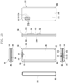
- the electronic device 200 may include a recess 201 formed to receive the first display 230 via structural coupling of the first housing 210 and the second housing 220.
- the recess 201 may have substantially the same size as the first display 230.
- the hinge cover 265 may be disposed between the first housing 210 and the second housing 220 to cover the hinge module (e.g., the hinge module 264 of FIG. 2D ).
- the hinge cover 265 may be covered by parts of the first housing 210 and the second housing 220 or exposed to the outside according to the unfolded state, folded state, or intermediate state of the electronic device 200. For example, when the electronic device 200 is in the unfolded state, the hinge cover 265 may not be exposed since the hinge cover is covered by the first housing 210 and the second housing 220.
- first housing 210 and the second housing 220 may operate while being pressed in an unfolding direction or a folding direction with reference to a designated inflection angle, through the hinge module (e.g., the hinge module 264 of FIG. 2D ).
- the hinge module e.g., the hinge module 264 of FIG. 2D .
- the electronic device 200 may include a first rear cover 240 disposed on the second surface 212 of the first housing 210, and a second rear cover 250 disposed on the fourth surface 222 of the second housing 220.
- at least a part of the first rear cover 240 may be integrally configured with the first lateral member 213.
- at least a part of the second rear cover 250 may be integrally configured with the second lateral member 223.
- at least one of the first rear cover 240 and the second rear cover 250 may be configured through a substantially transparent plate (e.g., a polymer plate or a glass plate including various coating layers) or an opaque plate.
- the first rear cover 240 may be formed of, for example, an opaque plate such as coated or colored glass, ceramic, a polymer, a metal (e.g., aluminum, stainless steel (STS), or magnesium), or a combination of at least two of the materials.
- the second rear cover 250 may be formed through, for example, a substantially transparent plate such as glass or polymer. Accordingly, the second display 235 may be disposed to be visible from the outside through the second rear cover 250 in the inner space of the second housing 220.
- the at least one camera device 216a and 225, the at least one sensor module 217a and 226, and/or the indicator may be disposed under active areas (display areas) of the displays 230 and 235 in the inner spaces of the at least one housing 210 and 220, and disposed to be in contact with an external environment through an opening perforated up to a cover member (e.g., a window layer (not shown) of the first display 230 and/or the second rear cover 250).
- some camera devices 216a and/or 225 or sensor modules 217a and/or 226 may be disposed to perform their functions without being visually exposed through the display 230 and/or 235.
- an area of the display 230 and/or 235 e.g., a display panel facing the camera device 216a and/or 225 and/or the sensor module 217a and/or 226 may not require a perforated opening.
- the unfolded state of the first housing 210 and the second housing 220 may include an operation state in which the folding angle between the first housing 210 and the second housing 220 is included in a first reference range (e.g., about 170 degrees to about 180 degrees).
- the folded state of the first housing 210 and the second housing 220 may include an operation state in which the folding angle between the first housing 210 and the second housing 220 is included in a second reference range (e.g., about 0 degrees to about 20 degrees).
- the first display 230 may include a display panel 231 (e.g., a flexible display panel) and one or more plates 232 or layers on which the display panel 231 (e.g., a flexible display panel) is seated.
- the one or more plates 232 may include a conductive plate (e.g., a Cu sheet or an SUS sheet) disposed between the display panel 231 and the support member assembly 260.
- the one or more plates 232 may be configured to have substantially the same area as the first display 230, and may be configured such that an area thereof facing the folding area 230c of the first display 230 is bendable.
- the first support member 261 may be disposed between the first area 231a of the first display 230 and a first printed circuit board 271.
- the second support member 262 may be disposed between the second area 231b of the first display 230 and a second printed circuit board 272.
- at least a part of the hinge module 264 and the at least one wiring member 263 may be disposed inside the support member assembly 260.
- the at least one wiring member 263 may be disposed in a direction (e.g., the x-axis direction) crossing the first support member 261 and the second support member 262.
- the at least one printed circuit board 270 may include the first printed circuit board 271 disposed to face the first support member 261, and the second printed circuit board 272 disposed to face the second support member 262.
- the first printed circuit board 271 and the second printed circuit board 272 may be disposed in an inner space formed by the support member assembly 260, the first housing 210, the second housing 220, the first rear cover 240, and/or the second rear cover 250.
- the first printed circuit board 271 and the second printed circuit board 272 may include a plurality of electronic components arranged to implement various functions of the electronic device 200.
- the electronic device may include, in the first space of the first housing 210, the first printed circuit board 271 disposed in a space formed through the first support member 261, a first battery 291 disposed at a position facing a first swelling hole 2611 of the first support member 261, at least one camera device 282 (e.g., the first camera device 216a and/or the second camera device 216b of FIG. 2A ), or at least one sensor module 281 (e.g., the first sensor module 217a and/or the second sensor module 217b of FIG. 2A ).
- the second space of the second housing 220 may include the second printed circuit board 272 disposed in a second space formed through the second support member 262, and a second battery 292 disposed at a position facing a second swelling hole 2621 of the second support member 262.
- the first housing 210 and the first support member 261 may be integrally configured.
- the second housing 220 and the second support member 262 may also be integrally configured.
- the first housing 210 may include a first rotation support surface 214
- the second housing 220 may include a second rotation support surface 224 corresponding to the first rotation support surface 214
- the first rotation support surface 214 and the second rotation support surface 224 may include a curved surface corresponding to (naturally connected to) a curved surface included in the hinge cover 265.
- the first rotation support surface 214 and the second rotation support surface 224 may cover the hinge cover 265 so that the hinge cover 265 is not exposed to the rear surface of the electronic device 200 or is minimally exposed.
- the first rotation support surface 214 and the second rotation support surface 224 may rotate along the curved surface included in the hinge cover 265 to maximally expose the hinge cover 265 to the rear surface of the electronic device 200.
- the first display 320 and/or the second display 330 may display information processed by the electronic device 300.
- the first display 320 and/or the second display 330 may display a content related to an application program executed by the processor 310.
- the first display 320 and/or the second display 330 may display a content related to a low power display mode (e.g., always on display (AOD)).
- the sleep mode of the electronic device 300 may include a state in which driving of the processor 310 (e.g., an application processor) is restricted.
- the first sensor 340 may be disposed in at least a part of an inner space of the first housing (e.g., the first housing 210 of FIG. 2A ) of the electronic device 300.
- the first sensor 340 may collect information (e.g., posture, angular velocity, and/or acceleration) related to movement of the first housing (e.g., the first housing 210 of FIG. 2A ) to provide the collected information to the processor 310.
- the first sensor 340 may include an inertial sensor, a motion sensor, a 6-axis sensor, a first gyro sensor, and/or a first acceleration sensor.
- the processor 310 may detect a folding angle of the electronic device 300.
- the processor 310 may detect the folding angle between the first housing (e.g., the first housing 210 of FIG. 2A ) and the second housing (e.g., the second housing 220 of FIG. 2A ), based on sensor data collected through the first sensor 340 and the second sensor 350.
- the processor 310 may detect the folding angle between the first housing (e.g., the first housing 210 of FIG. 2A ) and the second housing (e.g., the second housing 220 of FIG.
- the magnetic detection sensor may be disposed in the first housing (or the second housing) to detect a magnetic force generated from a magnetic material disposed in the second housing (or the first housing).
- the active state of the first display 320 and/or the second display 330 may include a state in which all pixels of a display (e.g., the first display 320 and/or the second display 330) are activated.
- the processor 310 e.g., the application processor
- the first sensor 340 and/or the second sensor 350 may be controlled by the application processor and/or the sensor hub processor.
- the processor 310 may detect a folding angle between the first housing (e.g., the first housing 210 of FIG. 2A ) and the second housing (e.g., the second housing 220 of FIG. 2A ), based on sensor data collected through a part (e.g., the first acceleration sensor) of the first sensor 340 and/or a part (e.g., the second acceleration sensor) of the second sensor 350.
- a folding angle between the first housing (e.g., the first housing 210 of FIG. 2A ) and the second housing (e.g., the second housing 220 of FIG. 2A ), based on sensor data collected through a part (e.g., the first acceleration sensor) of the first sensor 340 and/or a part (e.g., the second acceleration sensor) of the second sensor 350.
- the inactive state of the first display 320 and/or the second display 330 may include a state in which at least one pixel of the display (e.g., the first display 320 and/or the second display 330) is activated or a state in which all pixels of the display are inactivated.
- the application processor of the processor 310 may be inactivated, and the sensor hub processor may control the first sensor 340 and/or the second sensor 350.
- the processor 310 may select the first display 320 and/or the second display 330 as a display for displaying a content, based on the folding angle of the electronic device 300.
- the content may include a content related to an application program executed by the processor 310 or a content related to a low power display mode (e.g., AOD).
- the processor 310 may select the first display 320 to display a content.
- the first sub-mode may include a state in which a second surface (e.g., the second surface 212 of FIG. 2A ) of the first housing (e.g., the first housing 210 of FIG. 2A ) is placed on (or in contact with) the horizontal plane.
- the second sub-mode may include a state in which a lateral surface (e.g., the first lateral member 213 of FIG. 2A ) of the first housing (e.g., the first housing 210 of FIG. 2A ) and a lateral surface (e.g., the second lateral member 223 of FIG. 2A ) of the second housing (e.g., the second housing 220 of FIG.
- the processor 310 may determine that the second surface of the first housing is in a state of being placed on (or in contact with) the horizontal plane.
- the designated third range may include a range from about -25 degrees to about 25 degrees about the transverse axis, a range from about -12 degrees to about 12 degrees about the longitudinal axis, and a range from about 65 degrees to about 90 degrees about the vertical axis.
- the processor 310 may select the first sensor 340 and/or the second sensor 350 as a sensor to be used to detect rotation of the electronic device 300, based on the folding angle of the electronic device 300.
- the processor 310 may select the first sensor 340 and/or the second sensor 350 as the sensor to be used to detect rotation of the electronic device 300.
- the processor 310 may indicate that all axis directions of the first sensor 340 and the second sensor 350 are the same while the electronic device 300 is in the unfolded state.
- the processor 310 may select the second sensor 350 as the sensor to be used to detect rotation of the electronic device 300.
- the processor 310 may select the first sensor 340 and the second sensor 350 as the sensor to be used to detect rotation of the electronic device 300.
- the processor 310 may determine that the fourth surface of the second housing is in a state of being placed on the horizontal plane.
- the processor 310 may configure the display direction of the content, based on the orientation angle corresponding to the one surface of the electronic device 300 viewed by the user.
- the user may refer to a user who owns and/or operates the electronic device 300.
- the display direction of the content may refer to a direction in which a user's gaze is directed.
- the memory 360 may store various data used by at least one component (e.g., the processor 310, the first display 320, the second display 330, the first sensor 340, or the second sensor 350) of the electronic device 300.
- the data may include information related to a reference range and/or a designated range for classifying an operation state of the electronic device 300.
- the data may include sensor data collected by the first sensor 340 and/or the second sensor 350.
- a second housing e.g., the second housing 220 of FIG. 2A
- the hinge module so as to be foldable with respect to the first housing and, in an unfolded state, including a third surface (e.g., the third surface 221 of FIG. 2A ) facing the same direction as the first surface, a fourth surface (e.g., the fourth surface 222 of FIG. 2A ) facing a direction opposite to the third surface, and a second lateral surface (e.g., the second lateral surface 223 of FIG. 2A ) surrounding a second space between the third surface and the fourth surface, a first display (e.g., the display module 160 of FIG.
- the electronic device may further include a magnetic detection sensor disposed in the first space or the second space, wherein the processor is configured to, when the first display and/or the second display is in an active state, identify the folding angle between the first housing and the second housing by using the first sensor, the second sensor, and the magnetic detection sensor, and when the first display and the second display are in an inactive state, identify the folding angle between the first housing and the second housing through a part of the first sensor and a part of the second sensor.
- the processor is configured to, when the first display and/or the second display is in an active state, identify the folding angle between the first housing and the second housing by using the first sensor, the second sensor, and the magnetic detection sensor, and when the first display and the second display are in an inactive state, identify the folding angle between the first housing and the second housing through a part of the first sensor and a part of the second sensor.
- the first sensor and/or the second sensor may include an acceleration sensor and a gyro sensor, and the part of the first sensor and/or the second sensor may include the acceleration sensor.
- the content may include a content related to an application program or a content related to a low power display mode.
- FIGS. 5A , 5B , and 5C illustrate an example of switching a display direction of a second display in an electronic device in an intermediate state according to various embodiments.
- FIGS. 6A and 6B illustrate another example of switching a display direction of a second display in an electronic device in an intermediate state according to various embodiments.
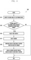
- the electronic device may identify whether the folding angle of the electronic device satisfies a designated first range (e.g., about 20 degrees to about 75 degrees).
- a designated first range e.g., about 20 degrees to about 75 degrees.
- the processor 310 may determine that the folding angle satisfies the designated first range.
- the processor 310 may determine that the folding angle satisfies the designated first range.
- the electronic device when the folding angle of the electronic device satisfies the designated first range (e.g., "Yes" in operation 403), in operation 405, the electronic device (e.g., the processor 120 or 310) may select a second display (e.g., the second display 235 of FIG. 2A or the second display 330 of FIG. 3 ) as a display for displaying a content.
- a second display e.g., the second display 235 of FIG. 2A or the second display 330 of FIG. 3
- power may be supplied to the second display.
- the content may include a content related to an application program executed by the processor 310 or a content related to a low power display mode (e.g., AOD).
- the electronic device may configure a display direction of the content, based on a second sensor (e.g., the second inertial sensor 283b of FIG. 2A or the second sensor 350 of FIG. 3 ).
- a second sensor e.g., the second inertial sensor 283b of FIG. 2A or the second sensor 350 of FIG. 3 .
- the processor 310 may configure a direction (e.g., the transformed direction of the X-axis in FIG. 5B ) facing an upper end of a virtual plane obtained by extending the transverse axis (e.g., the X-axis in FIG. 2A ) and the longitudinal axis (e.g., the Y-axis in FIG. 2A ) forming the orientation angle of the electronic device 300 as the display direction of the content, based on the orientation angle of the electronic device 300.
- a direction e.g., the transformed direction of the X-axis in FIG. 5B
- a virtual plane obtained by extending the transverse axis (e.g., the X-axis in FIG. 2A ) and the longitudinal axis (e.g., the Y-axis in FIG. 2A ) forming the orientation angle of the electronic device 300 as the display direction of the content, based on the orientation angle of the electronic device 300.
- the second display 330 may display a content 610, based on the second direction (e.g., direction (2)) oriented from the folding area 230c (e.g., the hinge module 264 of FIG. 2D ) toward the second housing 220.
- the second display 330 may output, to the display panel, the information related to the content drawn in the buffer of the second display 330 by the processor 310 based on the second direction.
- the second display 330 may output the information related to the content to the display panel from the second point 605.
- the electronic device 300 may display, on the second display 330, a content (e.g., time, weather, date, calendar, and/or notification information) related to a low power display mode (e.g., AOD).
- a content e.g., time, weather, date, calendar, and/or notification information
- a low power display mode e.g., AOD
- an electronic device may identify whether a first display (e.g., the first display 230 or 320) and/or a second display (e.g., the second display 235 or 330) is in an active state.
- the processor 310 may control the first display 320 or the second display 330 to be switched into the active state, based on an active event.
- the active event may be generated based on an input of a power button, fingerprint image acquisition of a fingerprint sensor, a touch input associated with the active event, and/or movement of the electronic device associated with the active event.
- the active state of the first display 320 and/or the second display 330 may include a state in which power is applied to a display (e.g., the first display 320 and/or the second display 330) and all pixels of the display (e.g., the first display 320 and/or the second display 330) are activated.
- the processor 310 e.g., the application processor
- the display e.g., the first display 320 and/or the second display 330.
- the electronic device may identify a folding angle of the electronic device by using a sensor (e.g., the first sensor 340 and the second sensor 350) of the electronic device.
- the processor 310 may detect the folding angle of the electronic device by using the first sensor 340, the second sensor 350, and/or the magnetic detection sensor (e.g., a Hall IC).
- the electronic device may identify a folding angle of the electronic device by using a part (e.g., the first acceleration sensor and the second acceleration sensor) of the sensor (e.g., the first sensor 340 and the second sensor 350) of the electronic device.
- the processor 310 may detect the folding angle of the electronic device by using the first acceleration sensor of the first sensor 340 and the second acceleration sensor of the second sensor 350.
- the inactive state of the first display 320 and/or the second display 330 may include a state in which at least one pixel of the display (e.g., the first display 320 and/or the second display 330) is activated or a state in which all pixels of the display are inactivated.
- the state in which at least one pixel of the display (e.g., the first display 320 and the second display 330) is activated may include a state in which power is applied to the display (e.g., the first display 320 and the second display 330), but only at least one pixel is activated and a scan rate is relatively low.
- the application processor of the processor 310 may be inactivated, and the sensor hub processor may control the first sensor 340 and/or the second sensor 350.
- FIG. 8 is a flowchart of configuring a display direction of a first display in an electronic device in an intermediate state according to various embodiments.
- operations may be performed sequentially, but are not necessarily performed sequentially.
- the order of the operations may be changed, and at least two operations may be performed in parallel.
- an electronic device of FIG. 8 may be the electronic device 101 of FIG. 1 , the electronic device 200 of FIG. 2A , or the electronic device 300 of FIG. 3 .
- FIGS. 9A , 9B , 10A , 10B , and 11 FIGS.
- FIGS. 9A and 9B illustrate an example of switching a display direction of a first display in an electronic device in an intermediate state according to various embodiments.
- FIGS. 10A and 10B illustrate another example of switching a display direction of a first display in an electronic device in an intermediate state according to various embodiments.
- FIG. 11 illustrates an example of configuring a display direction of a first display in an electronic device in an intermediate state according to various embodiments.
- the processor 310 may detect the folding angle of the electronic device by using a part (e.g., the first acceleration sensor) of the first sensor 340 and a part (e.g., the second acceleration sensor) of the second sensor 350.
- a part e.g., the first acceleration sensor
- a part e.g., the second acceleration sensor
- the electronic device may identify whether the folding angle of the electronic device satisfies a designated second range (e.g., about 75 degrees to about 170 degrees).
- a designated second range e.g., about 75 degrees to about 170 degrees.
- the processor 310 may determine that the folding angle satisfies the designated second range.
- the processor 310 may determine that the folding angle satisfies the designated second range.
- the processor 310 may determine that the folding angle satisfies the designated second range.
- FIG. 11 when a folding angle 1100 between the first housing 210 and the second housing 220 is included in the designated second range, the processor 310 may determine that the folding angle satisfies the designated second range.
- the processor 310 may select the first sensor 340 and the second sensor 350 as the sensor to be used to detect rotation of the electronic device 300.
- the designated third range may include a range from about -25 degrees to about 25 degrees about the transverse axis (e.g., the X-axis in FIG. 2A ), a range from about -12 degrees to about 12 degrees about the longitudinal axis (e.g., the Y-axis in FIG. 2A ), and a range from about 65 degrees to about 90 degrees about the vertical axis (e.g., the Z-axis in FIG. 2A ).
- the electronic device may configure a display direction of a content, based on a first sensor (e.g., the first inertial sensor 283a of FIG. 2A or the first sensor 340 of FIG. 3 ) and/or a second sensor (e.g., the second inertial sensor 283b of FIG. 2A or the second sensor 350 of FIG. 3 ) selected to detect rotation of the electronic device.
- a first sensor e.g., the first inertial sensor 283a of FIG. 2A or the first sensor 340 of FIG. 3
- a second sensor e.g., the second inertial sensor 283b of FIG. 2A or the second sensor 350 of FIG. 3
- the processor 310 may detect an orientation angle of the electronic device 300, based on sensor data collected through the second sensor 350. For example, the processor 310 may configure a second direction (e.g., direction (2) in FIG. 9B ) oriented from the folding area 230c (e.g., the hinge module 264 of FIG. 2D ) toward the second housing 220 as the display direction of the content, based on the orientation angle of the electronic device 300.
- a second direction e.g., direction (2) in FIG. 9B
- the folding area 230c e.g., the hinge module 264 of FIG. 2D
- the processor 310 may control the first display 320 to display another content (e.g., a control menu related to a video content) in a first area (e.g., the first area 231a of FIG. 2D ) of the first display 320.
- another content e.g., a control menu related to a video content
- a first area e.g., the first area 231a of FIG. 2D
- the first display 320 may display a content 1010, based on the third direction (e.g., direction (3)) oriented from the folding area 230c (e.g., the hinge module 264 of FIG. 2D ) toward the first housing 210.
- the first display 320 may output, to the display panel, the information related to the content drawn in the buffer of the first display 320 by the processor 310 based on the third direction.
- the first display 320 may output the information related to the content to the display panel from the fourth point 1005.
- the processor 310 may control the first display 320 such that a video content is displayed to be oriented in the third direction (e.g., direction (3)) in the first area (e.g., the first area 231a of FIG. 2D ) of the first display 320.
- the processor 310 may control the first display 320 to display another content (e.g., a control menu related to a video content) in the second area (e.g., the second area 231b of FIG. 2D ) of the first display 320.
- another content e.g., a control menu related to a video content
- the electronic device 300 may be changed from a state where the second surface (e.g., the second surface 212 of FIG. 2A ) of the first housing 210 is placed on the horizontal plane as shown in FIG. 9A to a state where the fourth surface (e.g., the fourth surface 222 of FIG. 2A ) of the second housing 220 is placed on the horizontal plane as shown in FIG. 10A .
- the electronic device 300 may switch the display direction of the video content from a state in which the content is displayed to be oriented in the second direction in the second area (e.g., the second area 231b of FIG. 2D ) of the first display 320 as shown in FIG.
- the electronic device 300 may switch the display direction of the video content from a state in which the content is displayed to be oriented in the third direction in the first area (e.g., the first area 231a of FIG. 2D ) of the first display 320 as shown in FIG. 10B to a state in which the content is displayed to be oriented in the second direction in the second area (e.g., the second area 231b of FIG. 2D ) of the first display 320 as shown in FIG. 9B .
- a state in which the content is displayed to be oriented in the third direction in the first area (e.g., the first area 231a of FIG. 2D ) of the first display 320 as shown in FIG. 10B to a state in which the content is displayed to be oriented in the second direction in the second area (e.g., the second area 231b of FIG. 2D ) of the first display 320 as shown in FIG. 9B .
- an electronic device e.g., the processor 120 of FIG. 1 or the processor 310 of FIG. 3
- the processor 310 may determine that the electronic device 300 is in the unfolded state. For example, as in operations 701 to 703 of FIG.
- the processor 310 when the first display 320 and/or the second display 330 is in an active state, the processor 310 (e.g., the application processor and/or the sensor hub processor) may detect a folding angle of the electronic device by using the first sensor 340, the second sensor 350, and/or the magnetic detection sensor (e.g., a Hall IC). For example, as in operations 701 and 705 of FIG. 7 , when the first display 320 and the second display 330 are in an inactive state, the processor 310 (e.g., the sensor hub processor) may detect the folding angle of the electronic device by using the first acceleration sensor of the first sensor 340 and the second acceleration sensor of the second sensor 350.
- the processor 310 e.g., the sensor hub processor
- the electronic device may select a first display (e.g., the first display 230 of FIG. 2A or the first display 320 of FIG. 3 ) as a display for displaying a content, based on the unfolded state of the electronic device.
- a first display e.g., the first display 230 of FIG. 2A or the first display 320 of FIG. 3
- the electronic device may configure a display direction of a content by using on a first sensor (e.g., the first inertial sensor 283a of FIG. 2A or the first sensor 340 of FIG. 3 ) or a second sensor (e.g., the second inertial sensor 283b of FIG. 2A or the second sensor 350 of FIG. 3 ).
- a first sensor e.g., the first inertial sensor 283a of FIG. 2A or the first sensor 340 of FIG. 3
- a second sensor e.g., the second inertial sensor 283b of FIG. 2A or the second sensor 350 of FIG. 3
- all axis directions of the first sensor 340 and the second sensor 350 may be the same when the electronic device 300 is in the unfolded state.
- the electronic device may display the content on the first display (e.g., the first display 230 of FIG. 2A or the first display 320 of FIG. 3 ), based on the display direction of the content.
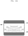
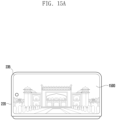
- the processor 310 may control the first display 320 to display a content 1300, based on the display direction of the content.
- the processor 310 may control the first display 320 to display a content 1310, based on the display direction of the content.
- FIG. 14 is a flowchart of configuring a display direction of a second display in an electronic device in a folded state according to various embodiments.
- operations may be performed sequentially, but are not necessarily performed sequentially.
- the order of the operations may be changed, and at least two operations may be performed in parallel.
- an electronic device of FIG. 14 may be the electronic device 101 of FIG. 1 , the electronic device 200 of FIG. 2A , or the electronic device 300 of FIG. 3 .
- FIGS. 15A and 15B illustrate an example of switching a display direction of a second display in an electronic device in a folded state according to various embodiments.
- the processor 310 when the first display 320 and/or the second display 330 is in an active state, the processor 310 (e.g., the application processor and/or the sensor hub processor) may detect a folding angle of the electronic device by using the first sensor 340, the second sensor 350, and the magnetic detection sensor (e.g., a Hall IC). For example, as in operations 701 and 705 of FIG. 7 , when the first display 320 and the second display 330 are in an inactive state, the processor 310 (e.g., the sensor hub processor) may detect the folding angle of the electronic device by using the first acceleration sensor of the first sensor 340 and the second acceleration sensor of the second sensor 350.
- the processor 310 e.g., the sensor hub processor
- the electronic device may configure a display direction of a content by using a first sensor (e.g., the first inertial sensor 283a of FIG. 2A or the first sensor 340 of FIG. 3 ).
- a first sensor e.g., the first inertial sensor 283a of FIG. 2A or the first sensor 340 of FIG. 3
- the processor 310 may select the first sensor 340 as a sensor to be used to detect rotation of the electronic device 300.
- the processor 310 may detect an orientation angle of the electronic device 300, based on sensor data collected through the first sensor 340 (e.g., the first acceleration sensor). For example, the processor 310 may configure the display direction of the content, based on the orientation angle of the electronic device 300.
- the sensor data may include data related to a change in the longitudinal axis (e.g., the Y-axis in FIG. 2A ) and the transverse axis (e.g., the X-axis in FIG. 2A ) of the first acceleration sensor.
- the electronic device may display the content on the second display (e.g., the second display 235 of FIG. 2A or the second display 330 of FIG. 3 ), based on the display direction of the content.
- the processor 310 may control the second display 330 (e.g., the second display 235 of FIG. 2A ) to display a content 1500, based on the display direction of the content.
- the processor 310 may control the second display 330 to display a content 1510, based on the display direction of the content.
- the electronic device 300 may switch the display direction of the content from a state in which the content 1510 is displayed to correspond to the portrait direction as shown in FIG. 15B to a state in which the content 1500 is displayed to correspond to the landscape direction as shown in FIG. 15A .
- first sensor being disposed in a first space of the first housing which is connected to a hinge module (e.g., the hinge module 264 of FIG. 2D ) and includes a first surface (e.g., the first surface 211 of FIG. 2A ), a second surface (e.g., the second surface 212 of FIG. 2A ) facing a direction opposite to the first surface, and a first lateral surface (e.g., the first lateral member 213 of FIG.
- a hinge module e.g., the hinge module 264 of FIG. 2D
- first surface e.g., the first surface 211 of FIG. 2A
- second surface e.g., the second surface 212 of FIG. 2A
- a first lateral surface e.g., the first lateral member 213 of FIG.
- the second sensor being disposed in a second space of the second housing which is connected to the hinge module so as to be foldable with respect to the first housing and, in an unfolded state, includes a third surface (e.g., the third surface 221 of FIG. 2A ) facing the same direction as the first surface, a fourth surface (e.g., the fourth surface 222 of FIG. 2A ) facing a direction opposite to the third surface, and a second lateral surface (e.g., the second lateral surface 223 of FIG.
- a third surface e.g., the third surface 221 of FIG. 2A
- a fourth surface e.g., the fourth surface 222 of FIG. 2A
- a second lateral surface e.g., the second lateral surface 223 of FIG.
- first display e.g., the display module 160 of FIG. 1 , the first display 230 of FIG. 2A , or the first display 320 of FIG. 3
- second display e.g., the display module 160 of FIG. 1 , the second display 235 of FIG. 2A , or the second display 330 of FIG.
- the identifying of the folding angle may include identifying the folding angle between the first housing and the second housing by using the first sensor, the second sensor, and a magnetic detection sensor when the first display and/or the second display is in an active state, or identifying the folding angle between the first housing and the second housing through a part of the first sensor and a part of the second sensor when the first display and the second display are in an inactive state.
- the first sensor and/or the second sensor may include an acceleration sensor and a gyro sensor, and the part of the first sensor and/or the second sensor may include the acceleration sensor.
- the method may further include selecting the second display when the first housing and the second housing are determined as being in a folded state, based on the folding angle between the first housing and the second housing, determining the display direction of the content, based on sensor data collected through the first sensor, and displaying the content on the second display, based on the display direction of the content.
- the method may further include selecting the first display when the first housing and the second housing are determined as being in the unfolded state, based on the folding angle between the first housing and the second housing, determining the display direction of the content, based on sensor data collected through the first sensor and/or the second sensor, and displaying the content on the first display, based on the display direction of the content.
- the method may include selecting the first display when the folding angle between the first housing and the second housing satisfies a designated second range different from the designated first range, determining the display direction of the content, based on sensor data collected through the first sensor and/or the second sensor, and displaying the content on the first display, based on the display direction of the content.
- the determining of the display direction of the content may include, when the sensor data collected through the first sensor and the second sensor does not satisfy the designated first condition, determining the display direction of the content, based on the sensor data collected through the first sensor and the second sensor.
- the displaying of the content on the second display may include displaying a content related to an application program when the second display is in an active state, or displaying a content related to a low power display mode when the second display is in an inactive state.
Landscapes
- Engineering & Computer Science (AREA)
- Theoretical Computer Science (AREA)
- General Engineering & Computer Science (AREA)
- Physics & Mathematics (AREA)
- General Physics & Mathematics (AREA)
- Human Computer Interaction (AREA)
- Computer Hardware Design (AREA)
- Signal Processing (AREA)
- Computer Graphics (AREA)
- Multimedia (AREA)
- Mathematical Physics (AREA)
- Telephone Set Structure (AREA)
- User Interface Of Digital Computer (AREA)
- Extrusion Moulding Of Plastics Or The Like (AREA)
- Push-Button Switches (AREA)
- Specific Sealing Or Ventilating Devices For Doors And Windows (AREA)
- Telephone Function (AREA)
Priority Applications (1)
| Application Number | Priority Date | Filing Date | Title |
|---|---|---|---|
| EP25213499.4A EP4712456A2 (de) | 2020-08-04 | 2021-07-19 | Faltbare elektronische vorrichtung zur steuerung der bildschirmrotation und betriebsverfahren dafür |
Applications Claiming Priority (2)
| Application Number | Priority Date | Filing Date | Title |
|---|---|---|---|
| KR1020200097145A KR102925911B1 (ko) | 2020-08-04 | 2020-08-04 | 화면 회전을 제어하기 위한 폴더블 전자 장치 및 그의 동작 방법 |
| PCT/KR2021/009244 WO2022030804A1 (ko) | 2020-08-04 | 2021-07-19 | 화면 회전을 제어하기 위한 폴더블 전자 장치 및 그의 동작 방법 |
Related Child Applications (2)
| Application Number | Title | Priority Date | Filing Date |
|---|---|---|---|
| EP25213499.4A Division EP4712456A2 (de) | 2020-08-04 | 2021-07-19 | Faltbare elektronische vorrichtung zur steuerung der bildschirmrotation und betriebsverfahren dafür |
| EP25213499.4A Division-Into EP4712456A2 (de) | 2020-08-04 | 2021-07-19 | Faltbare elektronische vorrichtung zur steuerung der bildschirmrotation und betriebsverfahren dafür |
Publications (4)
| Publication Number | Publication Date |
|---|---|
| EP4177717A1 true EP4177717A1 (de) | 2023-05-10 |
| EP4177717A4 EP4177717A4 (de) | 2023-12-13 |
| EP4177717B1 EP4177717B1 (de) | 2025-12-17 |
| EP4177717C0 EP4177717C0 (de) | 2025-12-17 |
Family
ID=80117368
Family Applications (2)
| Application Number | Title | Priority Date | Filing Date |
|---|---|---|---|
| EP21854226.4A Active EP4177717B1 (de) | 2020-08-04 | 2021-07-19 | Faltbare elektronische vorrichtung zur steuerung der bildschirmrotation und betriebsverfahren dafür |
| EP25213499.4A Pending EP4712456A2 (de) | 2020-08-04 | 2021-07-19 | Faltbare elektronische vorrichtung zur steuerung der bildschirmrotation und betriebsverfahren dafür |
Family Applications After (1)
| Application Number | Title | Priority Date | Filing Date |
|---|---|---|---|
| EP25213499.4A Pending EP4712456A2 (de) | 2020-08-04 | 2021-07-19 | Faltbare elektronische vorrichtung zur steuerung der bildschirmrotation und betriebsverfahren dafür |
Country Status (5)
| Country | Link |
|---|---|
| US (3) | US12014104B2 (de) |
| EP (2) | EP4177717B1 (de) |
| KR (2) | KR102925911B1 (de) |
| CN (1) | CN116075802A (de) |
| WO (1) | WO2022030804A1 (de) |
Families Citing this family (11)
| Publication number | Priority date | Publication date | Assignee | Title |
|---|---|---|---|---|
| CN115686407B (zh) * | 2022-06-30 | 2023-08-29 | 荣耀终端有限公司 | 显示方法与电子设备 |
| WO2024005408A1 (ko) * | 2022-06-30 | 2024-01-04 | 삼성전자주식회사 | 연성 회로 기판을 포함하는 폴더블 전자 장치 및 그 동작방법 |
| CN118675409A (zh) * | 2023-03-15 | 2024-09-20 | 摩托罗拉移动有限责任公司 | 可卷曲屏设备热缓解 |
| EP4661601A1 (de) * | 2023-04-11 | 2025-12-10 | Samsung Electronics Co., Ltd. | Elektronische vorrichtung mit fpcb |
| EP4697690A4 (de) * | 2023-05-24 | 2026-03-11 | Samsung Electronics Co Ltd | Verfahren zur anzeige eines hintergrundbildes und klappbare elektronische vorrichtung dafür |
| CN121420526A (zh) * | 2023-05-31 | 2026-01-27 | 三星电子株式会社 | 电子装置和用于控制电子装置的显示器的方法 |
| WO2024248476A1 (ko) * | 2023-06-02 | 2024-12-05 | 삼성전자주식회사 | 폴더블 전자 장치 및 그의 동작 방법 |
| WO2025014041A1 (ko) * | 2023-07-11 | 2025-01-16 | 삼성전자주식회사 | 센서를 이용하여 전자 장치의 상태를 식별하기 위한 전자 장치, 방법, 및, 저장 매체 |
| CN121336173A (zh) | 2023-07-14 | 2026-01-13 | 三星电子株式会社 | 用于改变显示器的显示模式的电子装置和方法以及存储介质 |
| WO2025018516A1 (ko) * | 2023-07-14 | 2025-01-23 | 삼성전자주식회사 | 디스플레이의 표시 모드를 변경하기 위한 전자 장치, 방법, 및 저장 매체 |
| US20250133158A1 (en) * | 2023-10-20 | 2025-04-24 | Motorola Mobility Llc | Deformable Electronic Devices and Corresponding Methods and Systems for Determining Deformation States |
Family Cites Families (24)
| Publication number | Priority date | Publication date | Assignee | Title |
|---|---|---|---|---|
| KR100500234B1 (ko) | 2002-11-05 | 2005-07-11 | 삼성전자주식회사 | 디스플레이장치 |
| KR100755851B1 (ko) | 2005-10-14 | 2007-09-07 | 엘지전자 주식회사 | 멀티미디어 디스플레이 방법, 이를 위한 이동 단말기, 및이동 단말기용 크래들 |
| KR101400284B1 (ko) | 2007-04-16 | 2014-05-30 | 삼성전자주식회사 | 폴딩형 멀티 디스플레이 장치 |
| US8860765B2 (en) * | 2008-09-08 | 2014-10-14 | Qualcomm Incorporated | Mobile device with an inclinometer |
| JP5653920B2 (ja) * | 2009-09-03 | 2015-01-14 | クゥアルコム・インコーポレイテッドQualcomm Incorporated | グラフィカルユーザインターフェース要素の配置および方向を示すための方法 |
| JP5783177B2 (ja) | 2010-08-05 | 2015-09-24 | 日本電気株式会社 | 携帯端末および表示制御方法 |
| CN103477304A (zh) * | 2011-02-10 | 2013-12-25 | 三星电子株式会社 | 包含触摸屏显示器的便携式设备以及控制它的方法 |
| KR102083918B1 (ko) | 2012-10-10 | 2020-03-04 | 삼성전자주식회사 | 멀티 디스플레이 장치 및 그 제어 방법 |
| KR102105959B1 (ko) | 2013-07-22 | 2020-04-29 | 엘지전자 주식회사 | 이미지 레이어를 제공하는 폴더블 디스플레이 디바이스 및 그 제어 방법 |
| CN104345273B (zh) | 2013-07-24 | 2017-11-24 | 中国国际航空股份有限公司 | 飞机辅助动力单元起动机性能检测方法和装置 |
| CN104375737B (zh) | 2013-08-12 | 2018-08-07 | 联想(北京)有限公司 | 一种信息处理方法以及电子设备 |
| KR101659032B1 (ko) * | 2014-07-25 | 2016-09-23 | 엘지전자 주식회사 | 이동 단말기 및 그것의 제어방법 |
| KR102342555B1 (ko) | 2014-11-10 | 2021-12-23 | 엘지전자 주식회사 | 이동 단말기 및 그것의 제어방법 |
| KR102537922B1 (ko) | 2015-09-11 | 2023-05-30 | 삼성전자 주식회사 | 디스플레이 사이의 각도를 측정하는 방법 및 이를 사용하는 전자 장치 |
| KR20170077670A (ko) | 2015-12-28 | 2017-07-06 | 삼성전자주식회사 | 컨텐츠를 제어하기 위한 방법 및 그 전자 장치 |
| KR102499110B1 (ko) * | 2016-01-14 | 2023-02-13 | 삼성전자 주식회사 | 디스플레이 제어 방법 및 이를 사용하는 전자 장치 |
| KR102433269B1 (ko) * | 2016-01-18 | 2022-08-17 | 삼성전자 주식회사 | 플렉서블 디스플레이 장치 및 디스플레이 제어 방법 |
| KR102516590B1 (ko) * | 2016-01-29 | 2023-04-03 | 삼성전자주식회사 | 전자 장치 및 전자 장치에서 디스플레이의 변형에 따라 기능을 실행하기 위한 방법 |
| KR20180132847A (ko) * | 2016-07-27 | 2018-12-12 | 선전 로욜 테크놀로지스 컴퍼니 리미티드 | 오동작을 방지하는 디스플레이 인터페이스 제어 방법, 장치 및 단말기 |
| KR102606422B1 (ko) | 2017-01-31 | 2023-11-29 | 삼성전자주식회사 | 디스플레이 제어 방법, 저장 매체 및 전자 장치 |
| KR20200026654A (ko) * | 2018-09-03 | 2020-03-11 | 안익준 | 폴더블 디스플레이가 구비된 스마트폰에서 정보 제공 방법 |
| KR102820040B1 (ko) * | 2018-10-22 | 2025-06-13 | 삼성전자주식회사 | 폴더블 전자 장치 및 그 콘텐츠의 다단 표시 방법 |
| KR102703500B1 (ko) * | 2019-01-10 | 2024-09-05 | 삼성전자주식회사 | 폴더블 디스플레이를 이용하여 이미지를 제공하는 방법 및 이를 지원하기 위한 전자 장치 |
| CN110806829B (zh) * | 2019-09-05 | 2021-05-11 | 华为技术有限公司 | 一种具有折叠屏的设备的显示方法及折叠屏设备 |
-
2020
- 2020-08-04 KR KR1020200097145A patent/KR102925911B1/ko active Active
-
2021
- 2021-07-19 WO PCT/KR2021/009244 patent/WO2022030804A1/ko not_active Ceased
- 2021-07-19 EP EP21854226.4A patent/EP4177717B1/de active Active
- 2021-07-19 CN CN202180057974.1A patent/CN116075802A/zh active Pending
- 2021-07-19 EP EP25213499.4A patent/EP4712456A2/de active Pending
-
2023
- 2023-02-02 US US18/105,084 patent/US12014104B2/en active Active
-
2024
- 2024-06-17 US US18/745,465 patent/US12411645B2/en active Active
-
2025
- 2025-09-08 US US19/322,023 patent/US20260003561A1/en active Pending
-
2026
- 2026-02-05 KR KR1020260023898A patent/KR20260021008A/ko active Pending
Also Published As
| Publication number | Publication date |
|---|---|
| WO2022030804A1 (ko) | 2022-02-10 |
| US12411645B2 (en) | 2025-09-09 |
| CN116075802A (zh) | 2023-05-05 |
| KR20220017078A (ko) | 2022-02-11 |
| US20260003561A1 (en) | 2026-01-01 |
| EP4712456A2 (de) | 2026-03-18 |
| US12014104B2 (en) | 2024-06-18 |
| US20240338164A1 (en) | 2024-10-10 |
| EP4177717B1 (de) | 2025-12-17 |
| EP4177717A4 (de) | 2023-12-13 |
| KR102925911B1 (ko) | 2026-02-11 |
| EP4177717C0 (de) | 2025-12-17 |
| US20230176803A1 (en) | 2023-06-08 |
| KR20260021008A (ko) | 2026-02-12 |
Similar Documents
| Publication | Publication Date | Title |
|---|---|---|
| EP4177717B1 (de) | Faltbare elektronische vorrichtung zur steuerung der bildschirmrotation und betriebsverfahren dafür | |
| US20230185507A1 (en) | Foldable electronic device and method for displaying information in foldable electronic device | |
| US20230053032A1 (en) | Electronic device including flexible display and method for controlling same | |
| US11907607B2 (en) | Electronic apparatus and method for outputting image thereof | |
| US11853546B2 (en) | Electronic device for controlling input mode according to folding angle, and method therefor | |
| US12493393B2 (en) | Method for operating flexible display, and electronic device | |
| US20240152307A1 (en) | Foldable electronic device and control method therefor | |
| US20230247130A1 (en) | Method for providing screen by using flexible display, and electronic device supporting same | |
| US20230122806A1 (en) | Electronic device for moving position of visual object located in folding area and method for controlling same | |
| US20250343847A1 (en) | Foldable electronic device and angle recognition method using same | |
| US12597157B2 (en) | Electronic device for correcting position of external device and operation method thereof | |
| EP4400948A1 (de) | Elektronische vorrichtung zur zustandserkennung unter verwendung eines sensors | |
| US12549663B2 (en) | Electronic device and method for displaying screen thereof | |
| EP4642017A1 (de) | Elektronische vorrichtung mit flexibler anzeige und verfahren zur identifizierung eines gefalteten oder nicht gefalteten zustands | |
| EP4583136A1 (de) | Elektronische vorrichtung mit seitenschlüssel | |
| US12190763B2 (en) | Electronic device including flexible display and operation method thereof | |
| US20250173108A1 (en) | Electronic device, and screen display method according to change of folding state using same | |
| US12535981B2 (en) | Electronic device, method, and storage medium for changing display mode of display | |
| EP4727166A1 (de) | Elektronische vorrichtung, verfahren und nichttransitorisches speichermedium zur bereitstellung von virtuellem vibrationsgeräusch | |
| US20260095517A1 (en) | Multi-foldable electronic device, and notification providing method of multi-foldable electronic device | |
| EP4583500A1 (de) | Elektronische vorrichtung und verfahren zur anzeige von auf mehreren fenstern basierenden benachrichtigungsinformationen in einer elektronischen vorrichtung | |
| CN118541664A (zh) | 电子装置及电子装置的屏幕显示方法 | |
| KR20240174440A (ko) | 가상 진동 사운드를 제공하기 위한 전자 장치, 방법 및 비 일시적 저장 매체 | |
| KR20240118627A (ko) | 플렉서블 디스플레이를 포함하는 전자 장치 및 접힘 상태 또는 펼침 상태를 확인하는 방법 |
Legal Events
| Date | Code | Title | Description |
|---|---|---|---|
| STAA | Information on the status of an ep patent application or granted ep patent |
Free format text: STATUS: THE INTERNATIONAL PUBLICATION HAS BEEN MADE |
|
| PUAI | Public reference made under article 153(3) epc to a published international application that has entered the european phase |
Free format text: ORIGINAL CODE: 0009012 |
|
| STAA | Information on the status of an ep patent application or granted ep patent |
Free format text: STATUS: REQUEST FOR EXAMINATION WAS MADE |
|
| 17P | Request for examination filed |
Effective date: 20230203 |
|
| AK | Designated contracting states |
Kind code of ref document: A1 Designated state(s): AL AT BE BG CH CY CZ DE DK EE ES FI FR GB GR HR HU IE IS IT LI LT LU LV MC MK MT NL NO PL PT RO RS SE SI SK SM TR |
|
| DAV | Request for validation of the european patent (deleted) | ||
| DAX | Request for extension of the european patent (deleted) | ||
| A4 | Supplementary search report drawn up and despatched |
Effective date: 20231110 |
|
| RIC1 | Information provided on ipc code assigned before grant |
Ipc: G09G 5/00 20060101ALN20231106BHEP Ipc: G09G 3/00 20060101ALN20231106BHEP Ipc: H04M 1/02 20060101ALI20231106BHEP Ipc: G06F 3/0488 20220101ALI20231106BHEP Ipc: G06F 1/3234 20190101ALI20231106BHEP Ipc: G06F 1/3206 20190101ALI20231106BHEP Ipc: G06F 1/16 20060101ALI20231106BHEP Ipc: G06F 3/147 20060101ALI20231106BHEP Ipc: G06F 3/14 20060101ALI20231106BHEP Ipc: G06F 3/0484 20220101ALI20231106BHEP Ipc: G06F 3/0346 20130101ALI20231106BHEP Ipc: G06F 3/038 20130101AFI20231106BHEP |
|
| GRAP | Despatch of communication of intention to grant a patent |
Free format text: ORIGINAL CODE: EPIDOSNIGR1 |
|
| STAA | Information on the status of an ep patent application or granted ep patent |
Free format text: STATUS: GRANT OF PATENT IS INTENDED |
|
| RIC1 | Information provided on ipc code assigned before grant |
Ipc: G06F 3/038 20130101AFI20250610BHEP Ipc: G06F 3/0346 20130101ALI20250610BHEP Ipc: G06F 3/0484 20220101ALI20250610BHEP Ipc: G06F 3/14 20060101ALI20250610BHEP Ipc: G06F 3/147 20060101ALI20250610BHEP Ipc: G06F 1/16 20060101ALI20250610BHEP Ipc: G06F 1/3206 20190101ALI20250610BHEP Ipc: G06F 1/3234 20190101ALI20250610BHEP Ipc: G06F 3/0488 20220101ALI20250610BHEP Ipc: G06F 3/04886 20220101ALI20250610BHEP Ipc: H04M 1/02 20060101ALI20250610BHEP Ipc: G09G 3/00 20060101ALN20250610BHEP Ipc: G09G 5/00 20060101ALN20250610BHEP |
|
| INTG | Intention to grant announced |
Effective date: 20250715 |
|
| GRAS | Grant fee paid |
Free format text: ORIGINAL CODE: EPIDOSNIGR3 |
|
| GRAA | (expected) grant |
Free format text: ORIGINAL CODE: 0009210 |
|
| STAA | Information on the status of an ep patent application or granted ep patent |
Free format text: STATUS: THE PATENT HAS BEEN GRANTED |
|
| AK | Designated contracting states |
Kind code of ref document: B1 Designated state(s): AL AT BE BG CH CY CZ DE DK EE ES FI FR GB GR HR HU IE IS IT LI LT LU LV MC MK MT NL NO PL PT RO RS SE SI SK SM TR |
|
| REG | Reference to a national code |
Ref country code: CH Ref legal event code: F10 Free format text: ST27 STATUS EVENT CODE: U-0-0-F10-F00 (AS PROVIDED BY THE NATIONAL OFFICE) Effective date: 20251217 Ref country code: GB Ref legal event code: FG4D |
|
| REG | Reference to a national code |
Ref country code: DE Ref legal event code: R096 Ref document number: 602021044719 Country of ref document: DE |
|
| U01 | Request for unitary effect filed |
Effective date: 20260106 |
|
| U07 | Unitary effect registered |
Designated state(s): AT BE BG DE DK EE FI FR IT LT LU LV MT NL PT RO SE SI Effective date: 20260109 |
|
| PG25 | Lapsed in a contracting state [announced via postgrant information from national office to epo] |
Ref country code: NO Free format text: LAPSE BECAUSE OF FAILURE TO SUBMIT A TRANSLATION OF THE DESCRIPTION OR TO PAY THE FEE WITHIN THE PRESCRIBED TIME-LIMIT Effective date: 20260317 |
|
| PG25 | Lapsed in a contracting state [announced via postgrant information from national office to epo] |
Ref country code: HR Free format text: LAPSE BECAUSE OF FAILURE TO SUBMIT A TRANSLATION OF THE DESCRIPTION OR TO PAY THE FEE WITHIN THE PRESCRIBED TIME-LIMIT Effective date: 20251217 |
|
| PG25 | Lapsed in a contracting state [announced via postgrant information from national office to epo] |
Ref country code: RS Free format text: LAPSE BECAUSE OF FAILURE TO SUBMIT A TRANSLATION OF THE DESCRIPTION OR TO PAY THE FEE WITHIN THE PRESCRIBED TIME-LIMIT Effective date: 20260317 |