EP4177724B1 - Procédé et appareil d'affichage d'image faciale, dispositif électronique et support de stockage - Google Patents
Procédé et appareil d'affichage d'image faciale, dispositif électronique et support de stockage Download PDFInfo
- Publication number
- EP4177724B1 EP4177724B1 EP21868404.1A EP21868404A EP4177724B1 EP 4177724 B1 EP4177724 B1 EP 4177724B1 EP 21868404 A EP21868404 A EP 21868404A EP 4177724 B1 EP4177724 B1 EP 4177724B1
- Authority
- EP
- European Patent Office
- Prior art keywords
- face
- face mask
- preset
- target
- speed
- Prior art date
- Legal status (The legal status is an assumption and is not a legal conclusion. Google has not performed a legal analysis and makes no representation as to the accuracy of the status listed.)
- Active
Links
Images



Classifications
-
- G—PHYSICS
- G06—COMPUTING OR CALCULATING; COUNTING
- G06T—IMAGE DATA PROCESSING OR GENERATION, IN GENERAL
- G06T13/00—Animation
- G06T13/20—Three-dimensional [3D] animation
- G06T13/40—Three-dimensional [3D] animation of characters, e.g. humans, animals or virtual beings
-
- G—PHYSICS
- G06—COMPUTING OR CALCULATING; COUNTING
- G06F—ELECTRIC DIGITAL DATA PROCESSING
- G06F3/00—Input arrangements for transferring data to be processed into a form capable of being handled by the computer; Output arrangements for transferring data from processing unit to output unit, e.g. interface arrangements
- G06F3/01—Input arrangements or combined input and output arrangements for interaction between user and computer
- G06F3/048—Interaction techniques based on graphical user interfaces [GUI]
- G06F3/0484—Interaction techniques based on graphical user interfaces [GUI] for the control of specific functions or operations, e.g. selecting or manipulating an object, an image or a displayed text element, setting a parameter value or selecting a range
- G06F3/04845—Interaction techniques based on graphical user interfaces [GUI] for the control of specific functions or operations, e.g. selecting or manipulating an object, an image or a displayed text element, setting a parameter value or selecting a range for image manipulation, e.g. dragging, rotation, expansion or change of colour
-
- G—PHYSICS
- G06—COMPUTING OR CALCULATING; COUNTING
- G06T—IMAGE DATA PROCESSING OR GENERATION, IN GENERAL
- G06T15/00—Three-dimensional [3D] image rendering
- G06T15/005—General purpose rendering architectures
-
- G—PHYSICS
- G06—COMPUTING OR CALCULATING; COUNTING
- G06F—ELECTRIC DIGITAL DATA PROCESSING
- G06F18/00—Pattern recognition
- G06F18/20—Analysing
- G06F18/25—Fusion techniques
-
- G—PHYSICS
- G06—COMPUTING OR CALCULATING; COUNTING
- G06F—ELECTRIC DIGITAL DATA PROCESSING
- G06F3/00—Input arrangements for transferring data to be processed into a form capable of being handled by the computer; Output arrangements for transferring data from processing unit to output unit, e.g. interface arrangements
- G06F3/01—Input arrangements or combined input and output arrangements for interaction between user and computer
- G06F3/048—Interaction techniques based on graphical user interfaces [GUI]
- G06F3/0484—Interaction techniques based on graphical user interfaces [GUI] for the control of specific functions or operations, e.g. selecting or manipulating an object, an image or a displayed text element, setting a parameter value or selecting a range
- G06F3/04842—Selection of displayed objects or displayed text elements
-
- G—PHYSICS
- G06—COMPUTING OR CALCULATING; COUNTING
- G06T—IMAGE DATA PROCESSING OR GENERATION, IN GENERAL
- G06T19/00—Manipulating three-dimensional [3D] models or images for computer graphics
- G06T19/20—Editing of three-dimensional [3D] images, e.g. changing shapes or colours, aligning objects or positioning parts
-
- G—PHYSICS
- G06—COMPUTING OR CALCULATING; COUNTING
- G06T—IMAGE DATA PROCESSING OR GENERATION, IN GENERAL
- G06T3/00—Geometric image transformations in the plane of the image
- G06T3/04—Context-preserving transformations, e.g. by using an importance map
-
- G—PHYSICS
- G06—COMPUTING OR CALCULATING; COUNTING
- G06T—IMAGE DATA PROCESSING OR GENERATION, IN GENERAL
- G06T2219/00—Indexing scheme for manipulating 3D models or images for computer graphics
- G06T2219/20—Indexing scheme for editing of 3D models
- G06T2219/2016—Rotation, translation, scaling
Definitions
- the present disclosure relates to the field of image processing technologies and, more specifically, to a face image displaying method and apparatus, an electronic device and a storage medium.
- WO 2018219120 A1 discloses an image display method for displaying the actual effect of different image processing by means of an augmented reality (AR) model
- US 20180182144 A1 discloses an information processing method for allowing a user to more intuitively perform operations for synthesis.
- the present invention is set out in the appended set of claims.
- the present disclosure provides a face image displaying method and apparatus, an electronic device, and a storage medium, which are used for solving the technical problem that users' needs for the diversity of interaction modes in a face image displaying process cannot be met at present.
- an embodiment of the present disclosure provides a face image displaying method, including:
- an embodiment of the present disclosure provides a corresponding electronic device, and in a third aspect, an embodiment of the present disclosure provides a computer-readable storage medium, in which corresponding computer-executable instructions are stored.
- the interactivity during a face image displaying process is enhanced by means of displaying dynamically a face mask sequence in accordance with a preset motion mode at a preset relative position of a face of an object, and fusing, after a target face mask of the face mask sequence is triggered by a user, the target face mask to the face of the object for display; and the effect of displaying a specific face mask on a face of an object can be achieved by means of fusing, after a target face mask is triggered by a user, the target face mask to the face of the object for display.
- the face image can be beautified and deformed.
- Many application scenarios are derived for a processed face image, in which the processed face image is directly applied, thus being unable to meet the users' needs for the diversity of interaction modes in a face image displaying process.
- a user can first generate a face mask sequence according to a face of an object after obtaining the face of the object through a terminal device (e.g., a personal computer, a notebook computer, a tablet computer, a smartphone, and other devices), where the face mask sequence includes a plurality of face masks therein.
- a terminal device e.g., a personal computer, a notebook computer, a tablet computer, a smartphone, and other devices
- the face mask sequence includes a plurality of face masks therein.
- a face mask of the face mask sequence can be a face mask directly corresponding to the face of the object, or a face mask generated after relevant processing (e.g., deforming processing, beautifying processing) for the face of the object.
- the face mask sequence may include therein a plurality of masks corresponding to different facial morphologies.
- the face masks of the face mask sequence can be arranged in accordance with a specific distribution rule.
- the face masks of the face mask sequence are arranged in accordance with a preset circumferential direction, where the preset circumferential direction is a direction in which the effect that the face mask sequence surrounds the face of the object is formed with the face of the object as a center and an overhead direction of the face of the object as a central axis.
- the face mask sequence is displayed dynamically in accordance with a preset motion mode, for example, the face mask sequence can rotate around the face of the object.
- a rotation speed at which the face mask sequence rotates around the face of the object can be determined according to a physical feature of a user, for example, it can be determined according to a mouth opening degree of the user, a smile degree of the user, and a related gesture of the user.
- illustration can be made by taking an example where the rotation speed is determined according to the mouth opening degree of the user.
- the rotation speed at which the face mask sequence rotates around the face of the object can increase with the mouth opening degree of the user, that is, the larger the mouth opening degree of the user, the faster the speed at which the face mask sequence rotates around the face of the object. It can be seen that the user, by adjusting the opening degree of the mouth, can accelerate and decelerate the rotation speed at which the face mask sequence rotates around the face of the object.
- the user When the user triggers any mask of the face mask sequence, for example, the user selects a mask of the face mask sequence by clicking a screen, it is a target face mask. After the triggering, the speed at which the face mask sequence rotates around the face of the object will first decrease until the target face mask moves directly in front of the face of the object. At this time, the rotation of the face mask sequence can be stopped, and the target face mask can be fused onto the face of the object for display. Furthermore, other face masks of the face mask sequence other than the target face mask can be faded out in accordance with a preset transparency change rule.
- the present disclosure through dynamically displaying a face mask sequence in accordance with a preset motion mode at a preset relative position of a face of an object, and fusing, after a target face mask of the face mask sequence is triggered by a user, the target face mask to the face of the object for display, an effect that the display mode of the face mask sequence is interactive with the face of the object is realized before the target face mask is triggered by the user; and, the target face mask is fused to the face of the object for display after the target face mask is triggered by the user, which can achieve the effect of displaying a specific face mask on the face of the object.
- the image processing method will be described in detail below through several specific implementations.
- FIG. 1 is a schematic flowchart of a face image displaying method shown according to an example embodiment of the present disclosure. As shown in FIG. 1 , the face image displaying method provided according to this embodiment includes the following steps.
- Step 101 display dynamically a face mask sequence in accordance with a preset motion mode at a preset relative position of a face of an object.
- the face mask sequence can be displayed dynamically in accordance with the preset motion mode at the preset relative position of the face of the object, where the face mask sequence can include a plurality of face masks corresponding to the face of the object.
- a face mask of the face mask sequence can be a face mask generated without processing for the face of the object or a face mask generated after relevant processing (e.g., deforming processing, beautifying processing) for the face of the object.
- relevant processing e.g., deforming processing, beautifying processing
- a related 3D face processing tool can be used.
- the face mask sequence may include therein a plurality of masks corresponding to different facial morphologies.
- the face masks of the face mask sequence can be arranged in accordance with a specific distribution rule.
- the face masks of the face mask sequence is arranged in accordance with a preset circumferential direction, or the face masks of the face mask sequence can also be arranged in accordance with a manner in which they are arranged successively in a preset direction.
- the preset circumferential direction can be a direction in which the effect that the face mask sequence surrounds the face of the object is formed with the face of the object as the center and the overhead direction of the face of the object as the central axis.
- the face mask sequence is also displayed dynamically in accordance with the preset motion mode, the face mask sequence rotates around the face of the object.
- the face mask sequence When the face masks of the face mask sequence are arranged in accordance with the manner in which the face masks are arranged successively in the preset direction, the face mask sequence can slide in front of the face of the object in accordance with the order in which the face masks are arranged.
- Step 102 in response to a trigger instruction acting on a target face mask, fuse the target face mask to the face of the object for display.
- any mask of the face mask sequence for example, the user selects a face mask of the face mask sequence by clicking a screen, it is a target face mask.
- the speed at which the face mask sequence rotates around the face of the object will first decrease until the target face mask moves directly in front of the face of the object.
- the rotation of the face mask sequence can be stopped, and the target face mask can be fused onto the face of the object for display.
- other face masks of the face mask sequence other than the target face mask can be faded out in accordance with a preset transparency change rule.
- the interactivity in a face image displaying process is enhanced by means of dynamically displaying a face mask sequence in accordance with a preset motion mode at a preset relative position of a face of an object, and fusing, after a target face mask of the face mask sequence is triggered by a user, the target face mask to the face of the object for display,; and the effect of displaying a specific face mask on a face of an object can be achieved by means of fusing, after a target face mask is triggered by a user, the target face mask the face of the object for display, thereby enhancing the fun and experience of the user interaction.
- the face masks included in the face mask sequence may include an original face mask corresponding to the face of the object, and may also include a deformed face mask generated by processing the original face mask with a 3D face processing tool.
- the face mask sequence may include eight face masks, in which two original face masks and six deformed face masks are included.
- eight face mask entities can be created first, then a pre-designed 3D model with a deformation effect is imported, and a deformer is added to each face mask entity to adjust a corresponding deformation degree. Since each face mask has a different deformation form, each deformation form needs to be imported separately, and multiple deformers can also be integrated into the same model.
- FIG. 2 is a schematic diagram of generating a single face mask shown according to an example embodiment of the present disclosure. As shown in FIG. 2 , an original vertex position of the face mask before deforming and a position offset of the face mask after deforming in the current model space can be obtained. Then, since it is necessary to ensure that the face mask is always displayed outwards relative to the face of the object, a displacement operation needs to be performed first, and then a rotation operation.
- the generated face mask can also be scaled, for example, to 90% of the original size, so that each face mask of the face mask sequence is a scaled face mask corresponding to the face of the object.
- the dynamic display of a single face mask is realized, it is possible to further realize the dynamic display of the face mask sequence in accordance with the preset motion mode at the preset relative position of the face of the object.
- the case where the face mask sequence includes eight face masks can be taken as an example for illustration.
- FIG. 3 is a schematic diagram of generating a face mask sequence shown according to an example embodiment of the present disclosure.
- the same deviation displacement and scaling ratio can be assigned thereto.
- the rotation angles are defined in turn according to an initialization order.
- the initialized eight face masks are placed at an interval of 45 degrees thereamong, so that the face mask sequence formed by the eight face masks is enclosed into a complete circle, thereby the face masks of the face mask sequence will be arranged in accordance with the preset circumferential direction when the face mask sequence is displayed.
- the eight face masks can be configured with an algorithm to control the selection of the face masks and assigned with different deformation models, in this way, it is possible to realize that the motion of these face masks can be uniformly controlled in a system-level script.
- FIG. 4 is a schematic scenario diagram of a triggering process of a face image displaying method shown according to an example embodiment of the present disclosure. As shown in FIG. 4 , a user can select a mask of the face mask sequence as the target face mask by clicking on a screen.
- the speed at which the face mask sequence rotates around the face of the object will first decrease until the target face mask moves directly in front of the face of the object.
- the rotation of the face mask sequence can be stopped, and the target face mask can be fused onto the face of the object for display.
- other face masks of the face mask sequence other than the target face mask can be faded out in accordance with a preset transparency change rule.
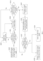
- FIG. 5 is a schematic flowchart of fusing and displaying steps after a target face mask is triggered shown according to an example embodiment of the present disclosure.
- step 102 in the embodiment mentioned above may specifically include the following steps.
- Step 1020 acquire the trigger instruction acting on the target face mask.
- a user can select a mask of the face mask sequence as the target face mask by clicking on a screen.
- Step 1021 determine whether a rotation speed is less than a preset target speed; if the result of the determination is yes, proceed with step 1022; if the result of the determination is no, proceed with step 1023.
- Step 1022 set a current rotation angle.
- Step 1023 reduce the rotation speed.
- Step 1024 determine whether the rotation speed is less than the preset target speed; if the result of the determination is yes, proceed with step 1025; if the result of the determination is no, proceed with step 1023.
- Step 1025 calculate a target rotation angle.
- the target face mask of the face mask sequence After the target face mask of the face mask sequence is triggered, it is necessary to determine whether a rotation speed is less than a preset target speed, where the preset target speed may be a rotation speed threshold. If the result of the determination is yes, it means that the current rotation speed of the face mask is relatively slow, and the target face mask can be controlled to move to the target position by directly calculating a target rotation angle, for example, the position directly in front of the face of the object, and then a subsequent fusing and displaying operation can be performed.
- a target rotation angle for example, the position directly in front of the face of the object
- the target rotation angle is a rotation angle at which the motion of the face mask is stopped. It is possible to continue to take the case that the face mask sequence includes eight face masks as an example for illustration. Since there must be a face mask directly in front of the user at stopping, and the rotation angle of the face mask is 0 at this time, the target rotation angle must be an integral multiple of 45.
- ⁇ is the target rotation angle
- ⁇ is the current rotation angle
- floor indicates acquisition of the largest integer less than the result in the brackets.
- 1 within the bracket can ensure that the direction of the relationship between the target angle and the current angle is consistent with the direction of rotation speed, and the current rotation angle is the current angle of a face corresponding to the respective face mask.
- Step 1026 record a number of a face mask that rotates to the target position.
- a number can be assigned to each face mask of the face mask sequence, and the number is used to uniquely identify each face mask, for example, the first face mask is assigned with a number 1, the second face mask is assigned with a number 2, the third face mask is assigned with a number 3, and the numbers are sequentially assigned until the eighth face mask is assigned with a number 8.
- the number of the face mask that rotates to the target position at a respective time instant is recorded at the current time. For example, at a first time instant, the first face mask corresponding to number 1 rotates to the target position; and at a second time instant, the second face mask corresponding to number 2 rotates to the target position.
- Step 1027 determine whether the target face mask rotates to the target position; if the result of the determination is no, proceed with step 1025; if the result of the determination is yes, proceed with step 1028 and step 1029.
- the target rotation angle of the target face mask When the target face mask is directly in front of the face of the object, that is, the target rotation angle of the target face mask is 0, it indicates that the target face mask reaches the target position, and at this time, the rotation of the face mask sequence can be stopped.
- the number corresponding to the target face mask is recorded; and during the rotation of the face mask sequence, if the number recorded at the current time is the number corresponding to the target face mask, it indicates that the target face mask is directly in front of the face of the object, and the rotation of the face mask sequence can be stopped at this time.
- the target face mask triggered by the user is the third face mask
- the number 3 is recorded; and during the rotation of the face mask sequence, when the face mask corresponding to the recorded number 3 rotates to the target position, that is, it indicates that the third face mask rotates to the target position, then the rotation of the face mask sequence is stopped.
- Step 1028 display a fused face image on the face of the object.
- the target face mask can be conformed to the face of the object in accordance with a preset path, and the target face mask and the face of the object can be fused to generate the fused face image, where the preset path points from a first position to a second position, and the first position is a position where the target face mask is currently located in the face mask sequence, and the second position is a position where the face of the object is currently located.
- the deviation value of the face mask in the Z-axis direction can be reduced, so as to realize the effect that all face masks move towards the face of the object by reducing a radius of a circle.
- the fused face image is displayed on the face of the object.
- Step 1029 fade out other face masks.
- other face masks other than the target face mask of the face mask sequence can be faded out in accordance with a preset transparency change rule.
- an alpha channel of a face mask that is not directly in front of the face of the object can be gradually lowered, where the alpha channel is used to adjust the transparency, so that the face mask that is not directly in front of the face of the object gradually becomes transparent.
- alpha max alpha ′ ⁇ ⁇ t ⁇ ⁇ t , 0
- alpha is the transparency of a face mask at a current frame
- alpha' is the transparency of the face mask at a previous frame
- ⁇ t is a time coefficient
- ⁇ t is a time difference between the current frame and the previous frame.
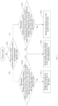
- FIG. 6 is a schematic flowchart of a face image displaying method shown according to another example embodiment of the present disclosure. As shown in FIG 6 , the face image displaying method provided according to this embodiment includes the following steps.
- Step 201 determine a rendering area and a non-rendering area according to a current position parameter of each texture element on each face mask of the face mask sequence and a position parameter of the face of the object, and render the rendering area exclusively.
- each face mask needs to be rendered. If each face mask is rendered in an undifferentiated and omnidirectional manner, it is easy to lead to excessive rendering computation, which results in consuming too many computing resources. Accordingly, the rendering area and the non-rendering area can be determined according to the current position parameter of each texture element on each face mask of the face mask sequence and the position parameter of the face of the object, and only the rendering area can be rendered.
- FIG. 7 is a schematic flowchart of rendering steps shown according to an example embodiment of the present disclosure.
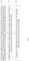
- the rendering steps mentioned above in this embodiment may include:
- the third direction may be a direction in which there is visual space occlusion between the face of the object and the face mask, for example, Z-axis direction in FIG. 3 .
- Step 2013, if it is in a backside area, determine whether the current position of the texture element is within a position range corresponding to the face of the object and is behind a characteristic key point of the face of the object in a third direction. If the result of the determination is yes, proceed with step 2015; if the result of the determination is no, proceed with step 2016.
- the frontal area and the backside area of the face mask can be completed by corresponding processing procedures, where a first processing procedure is only used for rendering the frontal area, and a second processing process is only used for rendering the backside area.
- the two processing procedures can share a texture element rendering engine for rendering, where the texture element rendering engine may sample the current face of the object to return a real-time portrait mask, so as to render the face mask.
- Whether the texture element needs to be rendered can be determined after determining whether the current position of the texture element is within the position range corresponding to the face of the object and is behind the characteristic key point (e.g., sideburns position) of the face of the object in the third direction (e.g., Z-axis direction).
- the characteristic key point e.g., sideburns position
- the texture element when the current position of the texture element is within the position range corresponding to the face of the object, the texture element may be in front of or behind the face of the object. However, if the current position of the texture element is in front of the sideburns position of the face of the object in the Z-axis direction, it can be determined that the texture element is in front of the face of the object, and it can be seen that the texture element is a visible part to a user, and therefore the texture element needs to be rendered.
- the texture element does not need to be rendered, thereby avoiding the waste of computing resources caused by an unnecessary rendering process.
- Step 2014 render the frontal area according to the face of the object.
- the rendering can be performed according to the face of the object, to display the specific appearance of the face of the object corresponding to the face mask.
- Step 2015 do not render a texture element of the face mask located in the non-rendering area.
- texture element of the face mask located in the non-rendering area no matter the texture element belongs to the frontal area or the backside area, it will not be rendered. It can be understood that the texture element in this area is set to be transparent.
- Step 2016, render the backside area with a preset fixed texture.
- the rendering can be performed according to the preset fixed texture, for example, the texture element can be rendered with gray.
- FIG. 8 is a schematic diagram of a rendered display result of the rendering steps shown in FIG. 7 .
- area A is located in the rendering area and belongs to the frontal area, and therefore it is rendered according to the face of the object, to display the specific appearance of the face of the object corresponding to the face mask;
- area B is located in the rendering area and belongs to the backside area, and therefore it is rendered with gray, for example.
- Step 202 display dynamically the face mask sequence in accordance with the preset motion mode at the preset relative position of the face of the object.
- step 101 in the embodiment shown in FIG. 1 for the implementation of step 202 in this embodiment.
- the determination of the speed of the preset motion can be made according to a physical feature of the user, for example, according to the mouth opening degree of the user, the smile degree of the user, and the related gesture of the user.
- illustration can be made by taking an example where the speed of the preset motion is determined according to the mouth opening degree of the user.
- the rotation speed at which the face mask sequence rotates around the face of the object can increase with the mouth opening degree of the user, that is, the larger the mouth opening degree of the user, the faster the speed at which the face mask sequence rotates around the face of the object. It can be seen that the user, by adjusting the opening degree of the mouth, can accelerate and decelerate the rotation speed at which the face mask sequence rotates around the face of the object.
- a characteristic parameter of a target part on the face of the object can be obtained first, and then a rotation speed is determined according to the characteristic parameter, and the face mask sequence is displayed dynamically in accordance with the rotation speed.
- a mouth characteristic parameter and an eye characteristic parameter of the face of the object can be obtained, where the mouth characteristic parameter includes a key point coordinate of an upper lip and a key point coordinate of a lower lip, and the eye characteristic parameter includes a key point coordinate of a left eye and a key point coordinate of a right eye.
- a first coordinate difference in a first direction (for example, the Y-axis) is determined according to the key point coordinate of the upper lip and the key point coordinate of the lower lip
- a second coordinate difference in a second direction (for example, the X-axis) is determined according to the key point coordinate of the left eye and the key point coordinate of the right eye.
- the characteristic parameter is determined according to a ratio of the first coordinate difference to the second coordinate difference, where the characteristic parameter can be used to characterize the mouth opening degree. It is worth noting that by determining the mouth opening degree with the ratio of the first coordinate difference to the second coordinate difference, the fluctuation of the mouth opening degree caused by the change of the distance between the face of the object and a camera can be avoided.
- the rotation speed is a first preset speed; if the characteristic parameter is greater than the preset first threshold, and a sum of the first preset speed and an additional speed is less than a second preset speed, the rotation speed is the sum of the first preset speed and the additional speed, where the additional speed is proportional to a characteristic parameter difference, and the characteristic parameter difference is a difference between the characteristic parameter and the preset first threshold; when the sum of the first preset speed and the additional speed is greater than or equal to the second preset speed, the rotation speed is determined as the second preset speed.
- the mouth opening detection threshold indicates determination of mouth opening only when the mouth opening degree is greater than that threshold
- the speed coefficient refers to a constant that needs to be multiplied when the mouth opening degree parameter is converted into the rotation speed.
- the characteristic parameter mentioned above is the mouth opening degree D
- the preset first threshold mentioned above is the mouth opening detection threshold d
- the first preset speed is the minimum rotation speed ⁇ min
- the additional speed is (D - d) ⁇ ⁇ ⁇
- the second preset speed is the maximum rotation speed ⁇ max .
- Step 203 in response to a trigger instruction acting on a target face mask, fuse the target face mask to the face of the object for display.
- step 102 in the embodiment shown in FIG. 1 for the implementation of step 203 in this embodiment, which will not be repeated herein.
- FIG. 9 is a schematic structure diagram of a face image displaying apparatus shown according to an example embodiment of the present disclosure.
- the face image displaying apparatus 300 provided according to this embodiment includes:
- the face mask sequence includes at least one deformed face mask corresponding to the face of the object.
- the display module 301 is specifically configured to: with the face of the object as a center and an overhead direction of the face of the object as a central axis, display dynamically the face mask sequence in a rotation motion mode, where the face masks of the face mask sequence are arranged in a preset circumferential direction.
- the face masks of the face mask sequence are scaled face masks corresponding to the face of the object.
- the display module 301 is specifically configured to:
- the acquiring module 302 is further configured to acquire a mouth characteristic parameter and an eye characteristic parameter of the face of the object, where the mouth characteristic parameter includes a key point coordinate of an upper lip and a key point coordinate of a lower lip, and the eye characteristic parameter includes a key point coordinate of a left eye and a key point coordinate of a right eye; and
- the processing module 303 is specifically configured to:
- the processing module 303 is further configured to determine whether the target face mask rotates to a target position, where the target position and the face of the object conform to a preset positional relationship.
- the target position is a position directly in front of the face of the object.
- the processing module 303 is further configured to: when the target face mask rotates to the target position, reduce a rotation speed of the rotation motion to a preset target speed.
- the processing module 303 is further configured to conform the target face mask to the face of the object in accordance with a preset path, and fuse the target face mask with the face of the object to generate a fused face image, where the preset path points from a first position to a second position, the first position is a position where the target face mask is currently located in the face mask sequence, and the second position is a position where the face of the object is currently located; and the display module 301 is further configured to display the fused face image on the face of the object.
- the display module 301 is further configured to fade out other face masks other than the target face mask of the face mask sequence in accordance with a preset transparency change rule.
- the processing module 303 is further configured to determine a rendering area and a non-rendering area according to a current position parameter of each texture element on each face mask of the face mask sequence and a position parameter of the face of the object, and render the rendering area exclusively.
- the processing module 303 is further configured to: if a current position of the texture element is located within a position range corresponding to the face of the object and is behind a characteristic key point of the face of the object in a third direction, determine that the texture element belongs to the non-rendering area.
- the processing module 303 is further configured to render the frontal area according to the face of the object; the processing module 303 is further configured to render the backside area with a preset fixed texture.
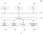
- FIG. 10 is a schematic structure diagram of an electronic device shown according to an embodiment of the present disclosure.
- FIG. 10 shows a schematic structure diagram of an electronic device 400 suitable for implementing the embodiments of the present disclosure.
- the terminal device in the embodiments of the present disclosure may include, but is not limited to, a mobile phone, a notebook computer, a digital broadcast receiver, a personal digital assistant(PDA), a tablet computer (PAD), a portable media player (PMP), a vehicular terminal (e.g., a vehicular navigation terminal) and other mobile terminals with an image acquiring function; as well as a digital TV, a desktop computer and other fixed terminals with an image acquiring device externally connected.
- PDA personal digital assistant
- PAD tablet computer
- PMP portable media player
- vehicular terminal e.g., a vehicular navigation terminal
- the electronic device shown in FIG. 10 is only an example, and should not bring any limitation to the function and the scope of use of the embodiments of the present disclosure.
- the electronic device 400 may include a processor (for example, a central processor, a graphics processor, etc.) 401, which may perform various appropriate actions and processing according to a program stored in a read-only memory (ROM) 402 or a program loaded from a memory 408 to a random access memory (RAM) 403.
- ROM read-only memory
- RAM random access memory
- various programs and data required for the operation of the electronic device 400 are also stored.
- the processor 401, ROM 402, and RAM 403 are connected to each other through a bus 404.
- An input/output (I/O) interface 405 is also connected to the bus 404.
- the memory is used to store programs for executing the methods described in the various method embodiments mentioned above; and the processor is configured to execute the programs stored in the memory.
- the following apparatuses may be connected to the I/O interface 405: an input apparatus 406, including, for example, a touch screen, a touch panel, a keyboard, a mouse, a camera, a microphone, a accelerometer, a gyroscope and the like; an output apparatus 407, including, for example, a liquid crystal display (LCD), a speaker, a vibrator and the like; a memory 408, including, for example, a magnetic tape, a hard disk and the like; and a communication apparatus 409.
- the communication apparatus 409 may allow the electronic device 400 to perform wireless or wired communication with other devices to exchange data.
- FIG. 10 shows the electronic device 400 with various kinds of apparatuses, it should be understood that it is not required to implement or have all the apparatuses shown in FIG. 10 . Alternatively, more or fewer apparatuses may be implemented or provided.
- an embodiment of the present disclosure includes a computer program product, which includes a computer program carried on a non-transient computer readable medium, and the computer program contains program codes for executing the method shown in the flowchart of an embodiment of the present disclosure.
- the computer program may be downloaded from a network through the communication apparatus 409 and installed, or installed from the memory 408, or installed from the ROM 402.
- the processor 401 When the computer program is executed by the processor 401, the above-mentioned functions defined in the methods of the embodiments of the present disclosure are executed.
- the above-mentioned computer readable medium in the present disclosure may be a computer readable signal medium, or a computer readable storage medium, or any combination thereof.
- the computer readable storage medium may be, for example, but not limited to, an electrical, magnetic, optical, electromagnetic, infrared, or semiconductor system, apparatus or device, or any combination thereof.
- the computer readable storage medium may include, but are not limited to: an electrically connected portable computer disk with one or more wires, a hard disk, a random access memory (RAM), a read-only memory (ROM), an erasable programmable read-only memory (EPROM or a flash), an optical fiber, a portable compact disc read-only memory (CD-ROM), an optical storage device, a magnetic storage device, or any suitable combination thereof.
- the computer readable storage medium may be any tangible medium that contains or stores a program, which may be used by or in combination with an instruction execution system, apparatus, or device.
- a computer readable signal medium may include a data signal propagated in a baseband or propagated as a part of a carrier wave, and program codes readable by a computer are carried therein.
- This propagated data signal may adopt many forms, including but not limited to, an electromagnetic signal, an optical signal, or any suitable combination thereof.
- the computer readable signal medium may also be any computer readable medium besides the computer readable storage medium, the computer readable signal medium may send, propagate, or transmit the program used by or in combination with the instruction execution system, apparatus, or device.
- the program codes contained on the computer readable medium may be transmitted by any suitable medium, including but not limited to: a wire, an optical cable, radio frequency (RF), etc., or any suitable combination thereof.
- the above-mentioned computer readable medium may be included in the above-mentioned electronic device; or it may exist alone without being assembled into the electronic device.
- the computer-readable medium carries one or more programs, and when the one or more programs are executed by the electronic device, the electronic device is caused to: display dynamically a face mask sequence in accordance with a preset motion mode at a preset relative position of a face of an object, where the face mask sequence includes a plurality of face masks corresponding to the face of the object; in response to a trigger instruction acting on a target face mask, fuse the target face mask to the face of the object for display, where the target face mask is any mask of the face mask sequence.
- the computer program codes for performing the operations of the present disclosure may be written in one or more programming languages or a combination thereof.
- the above-mentioned programming language includes, but is not limited to, an object-oriented programming language - such as Java, Smalltalk, C++, and also includes a conventional procedural programming language such as "C" language or similar programming language.
- the program codes may be executed entirely on a computer of a user, partly on a computer of a user, executed as an independent software package, partly executed on a computer of a user and partly executed on a remote computer, or entirely executed on a remote computer or server.
- the remote computer may be connected to a computer of a user through any kind of network including a local area network (LAN) or a wide area network (WAN), or may be connected to an external computer (for example, connected via the Internet through an Internet service provider).
- LAN local area network
- WAN wide area network
- an Internet service provider for example, connected via the Internet through an Internet service provider.
- a client and a server can communicate using any currently known network protocol such as hypertext transfer protocol (HTTP) or future developed network protocol, and can be interconnected with digital data communication of any form or medium (e.g., a communication network).
- HTTP hypertext transfer protocol
- Examples of the communication network include a local area network (LAN), a wide area network (WAN), an inter-network (e.g., the Internet), and a peer-to-peer network (e.g., an ad hoc peer-to-peer network), as well as any currently known or future developed network.
- each block in the flowcharts or block diagrams may represent a module, a program segment, or a part of codes, and the module, the program segment, or the part of codes contains one or more executable instructions for implementing a designated logical function.
- the functions marked in the blocks may also occur in a different order from the order marked in the drawings. For example, two blocks shown one after another may actually be executed substantially in parallel, or sometimes may be executed in a reverse order, which depends on the functions involved.
- each block in the block diagrams and/or flowcharts, and a combination of blocks in the block diagrams and/or flowcharts may be implemented by a dedicated hardware-based system that performs designated functions or operations, or may be implemented by a combination of a dedicated hardware and computer instructions.
- the modules involved in the description of the embodiments of the present disclosure may be implemented in software or hardware, where a name of a module does not constitute a limitation on the unit itself in a certain case.
- the display module can also be described as "a unit that displays the face of the object and the face mask sequence".
- exemplary types of hardware logic components include: a field programmable gate array (FPGA), an application specific integrated circuit (ASIC), an application specific standard part (ASSP), a system on chip (SOC), a complex programmable logic device (CPLD), etc.
- FPGA field programmable gate array
- ASIC application specific integrated circuit
- ASSP application specific standard part
- SOC system on chip
- CPLD complex programmable logic device
- a machine-readable medium may be a tangible medium that can contain or store a program for use by or in combination with an instruction execution system, apparatus or device.
- the machine-readable medium may be a machine-readable signal medium or a machine-readable storage medium.
- the machine-readable medium can include, but is not limited to, an electronic, magnetic, optical, electromagnetic, infrared, or semiconductor system, apparatus or device, or any suitable combination thereof.
- machine readable storage medium may include an electrically connected portable computer disk based on one or more wires, a hard disk, a random access memory (RAM), a read-only memory (ROM), an erasable programmable read-only memory (EPROM or flash memory), an optical fiber, a portable compact disc read-only memory (CD-ROM), an optical storage device, a magnetic storage device, or any suitable combination thereof.
- RAM random access memory
- ROM read-only memory
- EPROM or flash memory erasable programmable read-only memory
- CD-ROM portable compact disc read-only memory
- magnetic storage device or any suitable combination thereof.
Landscapes
- Engineering & Computer Science (AREA)
- Theoretical Computer Science (AREA)
- General Engineering & Computer Science (AREA)
- Physics & Mathematics (AREA)
- General Physics & Mathematics (AREA)
- Data Mining & Analysis (AREA)
- Human Computer Interaction (AREA)
- Computer Vision & Pattern Recognition (AREA)
- Bioinformatics & Computational Biology (AREA)
- Evolutionary Computation (AREA)
- Computer Graphics (AREA)
- Life Sciences & Earth Sciences (AREA)
- Artificial Intelligence (AREA)
- Bioinformatics & Cheminformatics (AREA)
- Evolutionary Biology (AREA)
- Architecture (AREA)
- Computer Hardware Design (AREA)
- Software Systems (AREA)
- Processing Or Creating Images (AREA)
- User Interface Of Digital Computer (AREA)
- Image Processing (AREA)
Claims (15)
- Procédé d'affichage d'image faciale, comprenant :l'affichage (101) dynamique d'une séquence de masques faciaux conformément à un mode de mouvement prédéfini en une position relative prédéfinie d'un visage d'un objet, dans lequel la séquence de masques faciaux comprend une pluralité de masques faciaux correspondant au visage de l'objet ;en réponse à une instruction de déclenchement agissant sur un masque facial cible, la fusion (102) du masque facial cible avec le visage de l'objet à afficher, dans lequel le masque facial cible est n'importe quel masque facial de la séquence de masques faciaux ;dans lequel l'affichage (101) dynamique de la séquence de masques faciaux conformément au mode de mouvement prédéfini à la position relative prédéfinie du visage de l'objet comprend :avec le visage de l'objet comme centre et une direction verticale du visage de l'objet comme axe central, l'affichage dynamique de la séquence de masques faciaux dans un mode de mouvement de rotation, dans lequel les masques faciaux de la séquence de masques faciaux sont disposés dans une direction circonférentielle prédéfinie ;dans lequel l'affichage dynamique de la séquence de masques faciaux dans le mode de mouvement de rotation comprend :l'acquisition d'un paramètre caractéristique d'une partie cible sur le visage de l'objet ;la détermination d'une vitesse de rotation du mouvement de rotation en fonction du paramètre caractéristique, et l'affichage dynamique de la séquence de masques faciaux conformément à la vitesse de rotation.
- Procédé d'affichage d'image faciale selon la revendication 1, dans lequel la séquence de masques faciaux comprend au moins un masque facial déformé correspondant au visage de l'objet.
- Procédé d'affichage d'image faciale selon la revendication 1 ou 2, dans lequel les masques faciaux de la séquence de masques faciaux sont des masques faciaux mis à l'échelle correspondant au visage de l'objet.
- Procédé d'affichage d'image faciale selon l'une quelconque des revendications 1 à 3, dans lequel l'acquisition du paramètre caractéristique de la partie cible sur le visage de l'objet comprend :l'acquisition d'un paramètre caractéristique de bouche et d'un paramètre caractéristique d'yeux du visage de l'objet, dans lequel le paramètre caractéristique de bouche comprend une coordonnée de point clé d'une lèvre supérieure et une coordonnée de point clé d'une lèvre inférieure, et le paramètre caractéristique d'yeux comprend une coordonnée de point clé d'un oeil gauche et une coordonnée de point clé d'un oeil droit ;la détermination d'une première différence de coordonnées dans une première direction en fonction de la coordonnée de point clé de la lèvre supérieure et de la coordonnée de point clé de la lèvre inférieure, et la détermination d'une seconde différence de coordonnées dans une deuxième direction en fonction de la coordonnée de point clé de l'œil gauche et de la coordonnée de point clé de l'œil droit ;la détermination du paramètre caractéristique en fonction d'un rapport entre la première différence de coordonnées et la seconde différence de coordonnées.
- Procédé d'affichage d'image faciale selon la revendication 4, dans lequel la détermination de la vitesse de rotation du mouvement de rotation en fonction du paramètre caractéristique comprend :si le paramètre caractéristique est inférieur ou égal à un premier seuil prédéfini, la détermination de la vitesse de rotation comme première vitesse prédéfinie ;si le paramètre caractéristique est supérieur au premier seuil prédéfini et qu'une somme de la première vitesse prédéfinie et d'une vitesse supplémentaire est inférieure à une seconde vitesse prédéfinie, la détermination de la vitesse de rotation comme une somme de la première vitesse prédéfinie et de la vitesse supplémentaire, dans lequel la vitesse supplémentaire est proportionnelle à une différence de paramètre caractéristique, et la différence de paramètre caractéristique est une différence entre le paramètre caractéristique et le premier seuil prédéfini ;lorsque la somme de la première vitesse prédéfinie et de la vitesse supplémentaire est supérieure ou égale à la seconde vitesse prédéfinie, la détermination de la vitesse de rotation comme seconde vitesse prédéfinie.
- Procédé d'affichage d'image faciale selon l'une quelconque des revendications 1 à 5, avant la fusion (102) du masque facial cible avec le visage de l'objet à afficher, comprenant en outre :
la détermination (1027) pour établir si le masque facial cible tourne vers une position cible, dans lequel la position cible et le visage de l'objet sont conformes à une relation de position prédéfinie. - Procédé d'affichage d'image faciale selon la revendication 6, dans lequel la position cible est une position directement devant le visage de l'objet.
- Procédé d'affichage d'image faciale selon la revendication 6 ou 7, lorsque le masque facial cible tourne vers la position cible, la réduction d'une vitesse de rotation du mouvement de rotation à une vitesse cible prédéfinie.
- Procédé d'affichage d'image faciale selon l'une quelconque des revendications 1 à 8, dans lequel la fusion (102) du masque facial cible avec le visage de l'objet à afficher comprend :la conformation du masque facial cible au visage de l'objet conformément à un chemin prédéfini, et la fusion du masque facial cible avec le visage de l'objet pour générer une image faciale fusionnée, dans lequel le chemin prédéfini pointe d'une première position à une seconde position, la première position étant une position à laquelle le masque facial cible est actuellement situé dans la séquence de masques faciaux, et la seconde position étant une position à laquelle le visage de l'objet est actuellement situé ; etl'affichage (1028) de l'image faciale fusionnée sur le visage de l'objet.
- Procédé d'affichage d'image faciale selon la revendication 9, dans lequel la fusion (102) du masque facial cible sur le visage de l'objet à afficher comprend en outre :
l'atténuation (1029) d'autres masques faciaux autres que le masque facial cible de la séquence de masques faciaux conformément à une règle de changement de transparence prédéfinie. - Procédé d'affichage d'image faciale selon l'une quelconque des revendications 1 à 10, comprenant en outre :
la détermination (201) d'une zone de rendu et d'une zone de non-rendu en fonction d'un paramètre de position actuelle de chaque élément de texture sur chaque masque facial de la séquence de masques faciaux et d'un paramètre de position du visage de l'objet, et le rendu de la zone de rendu exclusivement. - Procédé d'affichage d'image faciale selon la revendication 11, dans lequel la détermination (201) de la zone de rendu et de la zone de non-rendu en fonction du paramètre de position actuelle de chaque élément de texture sur chaque masque facial de la séquence de masques faciaux et du paramètre de position du visage de l'objet comprend :
si une position actuelle de l'élément de texture est située dans une plage de positions correspondant au visage de l'objet et se trouve derrière un point clé caractéristique du visage de l'objet dans une troisième direction, la détermination que l'élément de texture appartient à la zone de non-rendu. - Procédé d'affichage d'image faciale selon la revendication 12, dans lequel la zone de rendu comprend une zone frontale et une zone arrière, et le rendu de la zone de rendu comprend :le rendu (2014) de la zone frontale en fonction du visage de l'objet ;le rendu (2016) de la zone arrière avec une texture fixe prédéfinie.
- Dispositif électronique (400), comprenant :au moins un processeur (401) et une mémoire (408) ;dans lequel la mémoire (408) stocke des instructions exécutables par ordinateur; et le au moins un processeur (401) exécute les instructions exécutables par ordinateur stockées dans la mémoire (408), de sorte que le procédé d'affichage d'image faciale selon l'une quelconque des revendications 1 à 13 est exécuté par le au moins un processeur (401).
- Support de stockage lisible par ordinateur, dans lequel des instructions exécutables par ordinateur sont stockées, dans lequel les instructions exécutables par ordinateur, lorsqu'elles sont exécutées par un processeur, mettent en oeuvre le procédé d'affichage d'image faciale selon l'une quelconque des revendications 1 à 13.
Applications Claiming Priority (2)
| Application Number | Priority Date | Filing Date | Title |
|---|---|---|---|
| CN202010981627.5A CN112099712B (zh) | 2020-09-17 | 2020-09-17 | 人脸图像显示方法、装置、电子设备及存储介质 |
| PCT/CN2021/114237 WO2022057576A1 (fr) | 2020-09-17 | 2021-08-24 | Procédé et appareil d'affichage d'image faciale, dispositif électronique et support de stockage |
Publications (4)
| Publication Number | Publication Date |
|---|---|
| EP4177724A1 EP4177724A1 (fr) | 2023-05-10 |
| EP4177724A4 EP4177724A4 (fr) | 2023-12-06 |
| EP4177724B1 true EP4177724B1 (fr) | 2025-01-29 |
| EP4177724C0 EP4177724C0 (fr) | 2025-01-29 |
Family
ID=73760305
Family Applications (1)
| Application Number | Title | Priority Date | Filing Date |
|---|---|---|---|
| EP21868404.1A Active EP4177724B1 (fr) | 2020-09-17 | 2021-08-24 | Procédé et appareil d'affichage d'image faciale, dispositif électronique et support de stockage |
Country Status (7)
| Country | Link |
|---|---|
| US (1) | US11935176B2 (fr) |
| EP (1) | EP4177724B1 (fr) |
| JP (1) | JP7560208B2 (fr) |
| KR (1) | KR102933394B1 (fr) |
| CN (1) | CN112099712B (fr) |
| BR (1) | BR112023001930A2 (fr) |
| WO (1) | WO2022057576A1 (fr) |
Families Citing this family (3)
| Publication number | Priority date | Publication date | Assignee | Title |
|---|---|---|---|---|
| CN112099712B (zh) | 2020-09-17 | 2022-06-07 | 北京字节跳动网络技术有限公司 | 人脸图像显示方法、装置、电子设备及存储介质 |
| CN114241171B (zh) * | 2021-11-18 | 2025-09-19 | 北京航星机器制造有限公司 | 一种人脸差值面具三维模型构建方法及装置 |
| CN219628896U (zh) * | 2023-03-20 | 2023-09-05 | 深圳市艾佐科技创新有限公司 | 一种智能面罩 |
Family Cites Families (25)
| Publication number | Priority date | Publication date | Assignee | Title |
|---|---|---|---|---|
| US20030234871A1 (en) * | 2002-06-25 | 2003-12-25 | Squilla John R. | Apparatus and method of modifying a portrait image |
| US8028250B2 (en) * | 2004-08-31 | 2011-09-27 | Microsoft Corporation | User interface having a carousel view for representing structured data |
| JP4655212B2 (ja) * | 2005-08-26 | 2011-03-23 | 富士フイルム株式会社 | 画像処理装置、画像処理方法及び画像処理プログラム |
| US20130080976A1 (en) * | 2011-09-28 | 2013-03-28 | Microsoft Corporation | Motion controlled list scrolling |
| US10916044B2 (en) * | 2015-07-21 | 2021-02-09 | Sony Corporation | Information processing apparatus, information processing method, and program |
| US10430867B2 (en) * | 2015-08-07 | 2019-10-01 | SelfieStyler, Inc. | Virtual garment carousel |
| US20170092002A1 (en) * | 2015-09-30 | 2017-03-30 | Daqri, Llc | User interface for augmented reality system |
| CN105357466A (zh) * | 2015-11-20 | 2016-02-24 | 小米科技有限责任公司 | 视频通信方法及装置 |
| CN105979360A (zh) * | 2015-12-04 | 2016-09-28 | 乐视致新电子科技(天津)有限公司 | 一种渲染图像的处理方法及装置 |
| US20180000179A1 (en) * | 2016-06-30 | 2018-01-04 | Alan Jeffrey Simon | Dynamic face mask with configurable electronic display |
| US10534809B2 (en) * | 2016-08-10 | 2020-01-14 | Zeekit Online Shopping Ltd. | Method, system, and device of virtual dressing utilizing image processing, machine learning, and computer vision |
| JP2018152646A (ja) * | 2017-03-10 | 2018-09-27 | 株式会社リコー | 撮像装置、画像表示システム、操作方法およびプログラム |
| CN107247548B (zh) * | 2017-05-31 | 2018-09-04 | 腾讯科技(深圳)有限公司 | 图像显示方法、图像处理方法及装置 |
| KR20190022856A (ko) * | 2017-06-12 | 2019-03-06 | 미디어 그룹 코 엘티디 | 제어 방법, 제어기, 스마트 거울 및 컴퓨터 판독가능 저장매체 |
| CN109410119A (zh) * | 2017-08-18 | 2019-03-01 | 北京凤凰都市互动科技有限公司 | 面具图像变形方法及其系统 |
| JP6981106B2 (ja) * | 2017-08-29 | 2021-12-15 | 株式会社リコー | 撮像装置、画像表示システム、操作方法、プログラム |
| CN109034063A (zh) * | 2018-07-27 | 2018-12-18 | 北京微播视界科技有限公司 | 人脸特效的多人脸跟踪方法、装置和电子设备 |
| CN110619615A (zh) * | 2018-12-29 | 2019-12-27 | 北京时光荏苒科技有限公司 | 用于处理图像方法和装置 |
| CN110322416B (zh) * | 2019-07-09 | 2022-11-18 | 腾讯科技(深圳)有限公司 | 图像数据处理方法、装置以及计算机可读存储介质 |
| US11457196B2 (en) * | 2019-08-28 | 2022-09-27 | Snap Inc. | Effects for 3D data in a messaging system |
| CN110992493B (zh) * | 2019-11-21 | 2023-10-31 | 北京达佳互联信息技术有限公司 | 图像处理方法、装置、电子设备及存储介质 |
| US11381756B2 (en) * | 2020-02-14 | 2022-07-05 | Snap Inc. | DIY effects image modification |
| US11508135B2 (en) * | 2020-04-13 | 2022-11-22 | Snap Inc. | Augmented reality content generators including 3D data in a messaging system |
| CN111494934B (zh) * | 2020-04-16 | 2024-05-17 | 网易(杭州)网络有限公司 | 游戏中虚拟道具展示方法、装置、终端及存储介质 |
| CN112099712B (zh) * | 2020-09-17 | 2022-06-07 | 北京字节跳动网络技术有限公司 | 人脸图像显示方法、装置、电子设备及存储介质 |
-
2020
- 2020-09-17 CN CN202010981627.5A patent/CN112099712B/zh active Active
-
2021
- 2021-08-24 JP JP2023507827A patent/JP7560208B2/ja active Active
- 2021-08-24 KR KR1020237003737A patent/KR102933394B1/ko active Active
- 2021-08-24 BR BR112023001930A patent/BR112023001930A2/pt unknown
- 2021-08-24 EP EP21868404.1A patent/EP4177724B1/fr active Active
- 2021-08-24 WO PCT/CN2021/114237 patent/WO2022057576A1/fr not_active Ceased
-
2022
- 2022-11-30 US US18/060,128 patent/US11935176B2/en active Active
Also Published As
| Publication number | Publication date |
|---|---|
| EP4177724A1 (fr) | 2023-05-10 |
| EP4177724A4 (fr) | 2023-12-06 |
| CN112099712B (zh) | 2022-06-07 |
| KR102933394B1 (ko) | 2026-03-04 |
| US20230090457A1 (en) | 2023-03-23 |
| US11935176B2 (en) | 2024-03-19 |
| CN112099712A (zh) | 2020-12-18 |
| EP4177724C0 (fr) | 2025-01-29 |
| KR20230034351A (ko) | 2023-03-09 |
| BR112023001930A2 (pt) | 2023-03-28 |
| JP7560208B2 (ja) | 2024-10-02 |
| WO2022057576A1 (fr) | 2022-03-24 |
| JP2023537721A (ja) | 2023-09-05 |
Similar Documents
| Publication | Publication Date | Title |
|---|---|---|
| CN110766777B (zh) | 虚拟形象的生成方法、装置、电子设备及存储介质 | |
| US11935176B2 (en) | Face image displaying method and apparatus, electronic device, and storage medium | |
| US20230162452A1 (en) | Implementation and display of augmented reality | |
| EP4050561B1 (fr) | Procédé d'affichage fondé sur la réalité augmentée, dispositif, et support de stockage | |
| US12482205B2 (en) | Virtual model processing method and apparatus, electronic device and storage medium | |
| WO2023138559A1 (fr) | Procédé et appareil d'interaction de réalité virtuelle, dispositif, et support de stockage | |
| CN114742856B (zh) | 一种视频处理方法、装置、设备及介质 | |
| CN112965773B (zh) | 用于信息显示的方法、装置、设备和存储介质 | |
| WO2023284791A1 (fr) | Procédé de fonctionnement d'interface virtuelle, dispositif d'affichage monté sur la tête et support lisible par ordinateur | |
| CN114397961B (zh) | 头戴式显示设备控制方法、头戴式显示设备组件和介质 | |
| EP4543018A1 (fr) | Procédé et appareil d'affichage de sous-titre, dispositif et support | |
| US20230298265A1 (en) | Dynamic fluid effect processing method and apparatus, and electronic device and readable medium | |
| WO2024041623A1 (fr) | Procédé et appareil de génération de carte à effets spéciaux, dispositif, et support de stockage | |
| WO2024146337A1 (fr) | Procédé et appareil de rendu d'ombre, dispositif et support | |
| US20250061667A1 (en) | Control method and apparatus based on mixed reality, electronic device, and storage medium | |
| US20250157116A1 (en) | Sticker generation method and device | |
| WO2023231926A1 (fr) | Procédé et appareil de traitement d'image, dispositif, et support de stockage | |
| CN109472855A (zh) | 一种体绘制方法、装置及智能设备 | |
| CN117193587A (zh) | 3d空间的界面交互方法和ar设备 | |
| CN110619615A (zh) | 用于处理图像方法和装置 | |
| CN116071454A (zh) | 发丝处理方法、装置、设备及存储介质 | |
| CN115770386A (zh) | 控制运动物体运动的方法、装置、设备及介质 | |
| US20250157150A1 (en) | Image generation method, apparatus, electronic device, and storage medium | |
| US20240087202A1 (en) | Dynamic fluid display method and apparatus, electronic device, and readable medium | |
| CN117453324A (zh) | 数字化模型显示方法、设备、介质及光学扫描仪扫描系统 |
Legal Events
| Date | Code | Title | Description |
|---|---|---|---|
| STAA | Information on the status of an ep patent application or granted ep patent |
Free format text: STATUS: THE INTERNATIONAL PUBLICATION HAS BEEN MADE |
|
| PUAI | Public reference made under article 153(3) epc to a published international application that has entered the european phase |
Free format text: ORIGINAL CODE: 0009012 |
|
| STAA | Information on the status of an ep patent application or granted ep patent |
Free format text: STATUS: REQUEST FOR EXAMINATION WAS MADE |
|
| 17P | Request for examination filed |
Effective date: 20230131 |
|
| AK | Designated contracting states |
Kind code of ref document: A1 Designated state(s): AL AT BE BG CH CY CZ DE DK EE ES FI FR GB GR HR HU IE IS IT LI LT LU LV MC MK MT NL NO PL PT RO RS SE SI SK SM TR |
|
| A4 | Supplementary search report drawn up and despatched |
Effective date: 20231107 |
|
| RIC1 | Information provided on ipc code assigned before grant |
Ipc: G06T 19/20 20110101ALI20231031BHEP Ipc: G06T 13/40 20110101ALI20231031BHEP Ipc: G06F 3/0484 20220101AFI20231031BHEP |
|
| DAV | Request for validation of the european patent (deleted) | ||
| DAX | Request for extension of the european patent (deleted) | ||
| GRAP | Despatch of communication of intention to grant a patent |
Free format text: ORIGINAL CODE: EPIDOSNIGR1 |
|
| STAA | Information on the status of an ep patent application or granted ep patent |
Free format text: STATUS: GRANT OF PATENT IS INTENDED |
|
| RIC1 | Information provided on ipc code assigned before grant |
Ipc: G06T 19/20 20110101ALI20240709BHEP Ipc: G06T 13/40 20110101ALI20240709BHEP Ipc: G06F 3/0484 20220101AFI20240709BHEP |
|
| INTG | Intention to grant announced |
Effective date: 20240814 |
|
| GRAS | Grant fee paid |
Free format text: ORIGINAL CODE: EPIDOSNIGR3 |
|
| GRAA | (expected) grant |
Free format text: ORIGINAL CODE: 0009210 |
|
| STAA | Information on the status of an ep patent application or granted ep patent |
Free format text: STATUS: THE PATENT HAS BEEN GRANTED |
|
| AK | Designated contracting states |
Kind code of ref document: B1 Designated state(s): AL AT BE BG CH CY CZ DE DK EE ES FI FR GB GR HR HU IE IS IT LI LT LU LV MC MK MT NL NO PL PT RO RS SE SI SK SM TR |
|
| REG | Reference to a national code |
Ref country code: GB Ref legal event code: FG4D |
|
| REG | Reference to a national code |
Ref country code: CH Ref legal event code: EP |
|
| REG | Reference to a national code |
Ref country code: DE Ref legal event code: R096 Ref document number: 602021025667 Country of ref document: DE |
|
| REG | Reference to a national code |
Ref country code: IE Ref legal event code: FG4D |
|
| U01 | Request for unitary effect filed |
Effective date: 20250129 |
|
| U07 | Unitary effect registered |
Designated state(s): AT BE BG DE DK EE FI FR IT LT LU LV MT NL PT RO SE SI Effective date: 20250204 |
|
| PG25 | Lapsed in a contracting state [announced via postgrant information from national office to epo] |
Ref country code: RS Free format text: LAPSE BECAUSE OF FAILURE TO SUBMIT A TRANSLATION OF THE DESCRIPTION OR TO PAY THE FEE WITHIN THE PRESCRIBED TIME-LIMIT Effective date: 20250429 |
|
| PG25 | Lapsed in a contracting state [announced via postgrant information from national office to epo] |
Ref country code: PL Free format text: LAPSE BECAUSE OF FAILURE TO SUBMIT A TRANSLATION OF THE DESCRIPTION OR TO PAY THE FEE WITHIN THE PRESCRIBED TIME-LIMIT Effective date: 20250129 |
|
| PG25 | Lapsed in a contracting state [announced via postgrant information from national office to epo] |
Ref country code: ES Free format text: LAPSE BECAUSE OF FAILURE TO SUBMIT A TRANSLATION OF THE DESCRIPTION OR TO PAY THE FEE WITHIN THE PRESCRIBED TIME-LIMIT Effective date: 20250129 |
|
| PGFP | Annual fee paid to national office [announced via postgrant information from national office to epo] |
Ref country code: GB Payment date: 20250625 Year of fee payment: 5 |
|
| PG25 | Lapsed in a contracting state [announced via postgrant information from national office to epo] |
Ref country code: IS Free format text: LAPSE BECAUSE OF FAILURE TO SUBMIT A TRANSLATION OF THE DESCRIPTION OR TO PAY THE FEE WITHIN THE PRESCRIBED TIME-LIMIT Effective date: 20250529 Ref country code: NO Free format text: LAPSE BECAUSE OF FAILURE TO SUBMIT A TRANSLATION OF THE DESCRIPTION OR TO PAY THE FEE WITHIN THE PRESCRIBED TIME-LIMIT Effective date: 20250429 |
|
| PG25 | Lapsed in a contracting state [announced via postgrant information from national office to epo] |
Ref country code: HR Free format text: LAPSE BECAUSE OF FAILURE TO SUBMIT A TRANSLATION OF THE DESCRIPTION OR TO PAY THE FEE WITHIN THE PRESCRIBED TIME-LIMIT Effective date: 20250129 |
|
| PG25 | Lapsed in a contracting state [announced via postgrant information from national office to epo] |
Ref country code: GR Free format text: LAPSE BECAUSE OF FAILURE TO SUBMIT A TRANSLATION OF THE DESCRIPTION OR TO PAY THE FEE WITHIN THE PRESCRIBED TIME-LIMIT Effective date: 20250430 |
|
| U1N | Appointed representative for the unitary patent procedure changed after the registration of the unitary effect |
Representative=s name: MARKS & CLERK LLP; GB |
|
| U20 | Renewal fee for the european patent with unitary effect paid |
Year of fee payment: 5 Effective date: 20250716 |
|
| PG25 | Lapsed in a contracting state [announced via postgrant information from national office to epo] |
Ref country code: SM Free format text: LAPSE BECAUSE OF FAILURE TO SUBMIT A TRANSLATION OF THE DESCRIPTION OR TO PAY THE FEE WITHIN THE PRESCRIBED TIME-LIMIT Effective date: 20250129 |
|
| PG25 | Lapsed in a contracting state [announced via postgrant information from national office to epo] |
Ref country code: CZ Free format text: LAPSE BECAUSE OF FAILURE TO SUBMIT A TRANSLATION OF THE DESCRIPTION OR TO PAY THE FEE WITHIN THE PRESCRIBED TIME-LIMIT Effective date: 20250129 |
|
| PG25 | Lapsed in a contracting state [announced via postgrant information from national office to epo] |
Ref country code: SK Free format text: LAPSE BECAUSE OF FAILURE TO SUBMIT A TRANSLATION OF THE DESCRIPTION OR TO PAY THE FEE WITHIN THE PRESCRIBED TIME-LIMIT Effective date: 20250129 |
|
| PLBE | No opposition filed within time limit |
Free format text: ORIGINAL CODE: 0009261 |
|
| STAA | Information on the status of an ep patent application or granted ep patent |
Free format text: STATUS: NO OPPOSITION FILED WITHIN TIME LIMIT |
|
| REG | Reference to a national code |
Ref country code: CH Ref legal event code: L10 Free format text: ST27 STATUS EVENT CODE: U-0-0-L10-L00 (AS PROVIDED BY THE NATIONAL OFFICE) Effective date: 20251210 |
|
| 26N | No opposition filed |
Effective date: 20251030 |
|
| REG | Reference to a national code |
Ref country code: CH Ref legal event code: H13 Free format text: ST27 STATUS EVENT CODE: U-0-0-H10-H13 (AS PROVIDED BY THE NATIONAL OFFICE) Effective date: 20260324 |
|
| PG25 | Lapsed in a contracting state [announced via postgrant information from national office to epo] |
Ref country code: MC Free format text: LAPSE BECAUSE OF FAILURE TO SUBMIT A TRANSLATION OF THE DESCRIPTION OR TO PAY THE FEE WITHIN THE PRESCRIBED TIME-LIMIT Effective date: 20250129 |
|
| PG25 | Lapsed in a contracting state [announced via postgrant information from national office to epo] |
Ref country code: CH Free format text: LAPSE BECAUSE OF NON-PAYMENT OF DUE FEES Effective date: 20250831 |