EP4177920B1 - Niederspannungsschalterpol - Google Patents
Niederspannungsschalterpol Download PDFInfo
- Publication number
- EP4177920B1 EP4177920B1 EP21206994.2A EP21206994A EP4177920B1 EP 4177920 B1 EP4177920 B1 EP 4177920B1 EP 21206994 A EP21206994 A EP 21206994A EP 4177920 B1 EP4177920 B1 EP 4177920B1
- Authority
- EP
- European Patent Office
- Prior art keywords
- arc
- switch pole
- breaking
- insulating
- wall
- Prior art date
- Legal status (The legal status is an assumption and is not a legal conclusion. Google has not performed a legal analysis and makes no representation as to the accuracy of the status listed.)
- Active
Links
Images






Classifications
-
- H—ELECTRICITY
- H01—ELECTRIC ELEMENTS
- H01H—ELECTRIC SWITCHES; RELAYS; SELECTORS; EMERGENCY PROTECTIVE DEVICES
- H01H1/00—Contacts
- H01H1/64—Protective enclosures, baffle plates, or screens for contacts
-
- H—ELECTRICITY
- H01—ELECTRIC ELEMENTS
- H01H—ELECTRIC SWITCHES; RELAYS; SELECTORS; EMERGENCY PROTECTIVE DEVICES
- H01H9/00—Details of switching devices, not covered by groups H01H1/00 - H01H7/00
- H01H9/30—Means for extinguishing or preventing arc between current-carrying parts
- H01H9/34—Stationary parts for restricting or subdividing the arc, e.g. barrier plate
- H01H9/346—Details concerning the arc formation chamber
-
- H—ELECTRICITY
- H01—ELECTRIC ELEMENTS
- H01H—ELECTRIC SWITCHES; RELAYS; SELECTORS; EMERGENCY PROTECTIVE DEVICES
- H01H33/00—High-tension or heavy-current switches with arc-extinguishing or arc-preventing means
- H01H33/60—Switches wherein the means for extinguishing or preventing the arc do not include separate means for obtaining or increasing flow of arc-extinguishing fluid
- H01H33/66—Vacuum switches
- H01H33/662—Housings or protective screens
- H01H33/66207—Specific housing details, e.g. sealing, soldering or brazing
-
- H—ELECTRICITY
- H01—ELECTRIC ELEMENTS
- H01H—ELECTRIC SWITCHES; RELAYS; SELECTORS; EMERGENCY PROTECTIVE DEVICES
- H01H3/00—Mechanisms for operating contacts
- H01H3/32—Driving mechanisms, i.e. for transmitting driving force to the contacts
- H01H3/46—Driving mechanisms, i.e. for transmitting driving force to the contacts using rod or lever linkage, e.g. toggle
-
- H—ELECTRICITY
- H01—ELECTRIC ELEMENTS
- H01H—ELECTRIC SWITCHES; RELAYS; SELECTORS; EMERGENCY PROTECTIVE DEVICES
- H01H9/00—Details of switching devices, not covered by groups H01H1/00 - H01H7/00
- H01H9/30—Means for extinguishing or preventing arc between current-carrying parts
-
- H—ELECTRICITY
- H01—ELECTRIC ELEMENTS
- H01H—ELECTRIC SWITCHES; RELAYS; SELECTORS; EMERGENCY PROTECTIVE DEVICES
- H01H9/00—Details of switching devices, not covered by groups H01H1/00 - H01H7/00
- H01H9/30—Means for extinguishing or preventing arc between current-carrying parts
- H01H9/34—Stationary parts for restricting or subdividing the arc, e.g. barrier plate
-
- H—ELECTRICITY
- H01—ELECTRIC ELEMENTS
- H01H—ELECTRIC SWITCHES; RELAYS; SELECTORS; EMERGENCY PROTECTIVE DEVICES
- H01H9/00—Details of switching devices, not covered by groups H01H1/00 - H01H7/00
- H01H9/30—Means for extinguishing or preventing arc between current-carrying parts
- H01H9/34—Stationary parts for restricting or subdividing the arc, e.g. barrier plate
- H01H9/36—Metal parts
-
- H—ELECTRICITY
- H01—ELECTRIC ELEMENTS
- H01H—ELECTRIC SWITCHES; RELAYS; SELECTORS; EMERGENCY PROTECTIVE DEVICES
- H01H9/00—Details of switching devices, not covered by groups H01H1/00 - H01H7/00
- H01H9/30—Means for extinguishing or preventing arc between current-carrying parts
- H01H9/34—Stationary parts for restricting or subdividing the arc, e.g. barrier plate
- H01H9/36—Metal parts
- H01H9/362—Mounting of plates in arc chamber
-
- H—ELECTRICITY
- H01—ELECTRIC ELEMENTS
- H01H—ELECTRIC SWITCHES; RELAYS; SELECTORS; EMERGENCY PROTECTIVE DEVICES
- H01H9/00—Details of switching devices, not covered by groups H01H1/00 - H01H7/00
- H01H9/30—Means for extinguishing or preventing arc between current-carrying parts
- H01H9/34—Stationary parts for restricting or subdividing the arc, e.g. barrier plate
- H01H2009/348—Provisions for recirculation of arcing gasses to improve the arc extinguishing, e.g. move the arc quicker into the arcing chamber
-
- H—ELECTRICITY
- H01—ELECTRIC ELEMENTS
- H01H—ELECTRIC SWITCHES; RELAYS; SELECTORS; EMERGENCY PROTECTIVE DEVICES
- H01H9/00—Details of switching devices, not covered by groups H01H1/00 - H01H7/00
- H01H9/30—Means for extinguishing or preventing arc between current-carrying parts
- H01H9/34—Stationary parts for restricting or subdividing the arc, e.g. barrier plate
- H01H9/342—Venting arrangements for arc chutes
-
- H—ELECTRICITY
- H01—ELECTRIC ELEMENTS
- H01H—ELECTRIC SWITCHES; RELAYS; SELECTORS; EMERGENCY PROTECTIVE DEVICES
- H01H9/00—Details of switching devices, not covered by groups H01H1/00 - H01H7/00
- H01H9/30—Means for extinguishing or preventing arc between current-carrying parts
- H01H9/46—Means for extinguishing or preventing arc between current-carrying parts using arcing horns
Definitions
- the present invention relates to a switch pole for a switching device to be used in low-voltage electrical systems.
- the invention likewise relates to a switching device comprising one or more of said switch poles.
- Low voltage switching devices such as for example circuit breakers, disconnectors, contactors, or the like, comprise one or more switch poles, each including one or more fixed contacts and movable contacts that can be coupled to and uncoupled from one another.
- Switching devices of the known art also comprise driving means designed to move the movable contacts relative to said fixed contacts, so that these electric contacts can be mutually couple or uncoupled, thereby allowing or preventing electric currents to flow along the switch poles.
- the driving means comprise, for instance, mechanisms, which terminate, for example, in a shaft operatively connected to said movable contacts.
- a switching device In order to break currents circulating along the switch poles, such arcing phenomena have to be extinguished as quickly as possible.
- a switching device generally comprises, for each switch pole, an arc chamber including a number of arc-breaking plates positioned near the electric contacts and designed to cool and split possible electric arcs raising between the electric contacts.
- the document EP 3 048 625 A1 discloses a switch pole according to the preamble of claim 1.
- a problem normally present in switching devices of known type consists in that an uneven distribution of electric arcs among the arc-breaking plates of the arc chamber often occurs during opening manoeuvres. As a result, the arc-quenching action exerted by the arc-breaking plates is not uniform and efficient.
- the main of the present invention is to provide a switch pole for low voltage switching devices, which allows overcoming or mitigating the above-mentioned shortcomings.
- the present invention is aimed at providing a switch pole, in which a more uniform utilization of the arc breaking plates of the arc chamber is ensured.
- a further object of the present invention is to provide a switch pole, in which arcing phenomena towards parts outside the arc-extinguishing area of the switch pole are prevented or remarkably reduced.
- a still further object of the present invention is to provide a switch pole that is reliable in operation and relatively easy and inexpensive to manufacture at industrial level.
- the switch pole comprises an insulating casing, which defines an internal space including a contact area and an arc extinguishing area.
- Said insulating casing comprises an insulating wall partially separating said contact area from said arc extinguishing area.
- the insulating wall is arranged in said internal space in an opposite position relative to said fixed contact assembly and extends from an outer wall of the insulating casing towards the fixed contact assembly.
- the insulating wall includes a channel passing through said insulating wall and connecting said contact area to said arc-extinguishing area.
- the switch pole further comprises a fixed contact assembly and a movable contact assembly positioned in the contact area of the switch pole.
- the fixed contact assembly and the movable contact assembly include, respectively, one or more fixed contacts and one or more movable contacts, which can be mutually coupled or uncoupled.
- the fixed contact assembly is arranged at a rear wall of the insulating casing.
- the movable contact assembly of the switch pole is reversibly movable between a first position, in which said movable contacts are coupled to said fixed contacts, and a second position, in which said movable contacts are spaced apart from said fixed contacts.
- the switch pole further comprises an arc chamber positioned in the arc extinguishing area of the switch pole.
- the arc chamber comprises a plurality of conductive arc-breaking plates.
- the arc chamber comprises an insulating enclosure that can be removably fixed to the insulating casing of the switch pole.
- the arc-breaking plates of the arc chamber are fixed to said insulating enclosure.
- the arc-breaking plates are arranged at subsequent positions between a front wall and a rear wall of the insulating casing.
- the above-mentioned arc-breaking plates thus comprises a terminal arc-breaking plate arranged in distal position from the above-mentioned fixed contact assembly in comparison to the other arc-breaking plates of said arc-chamber.
- the terminal arc-breaking plate is arranged at a front wall of the insulating casing, thereby in an opposite position with respect to the fixed contact assembly of the switch pole.
- the terminal arc-breaking plate is arranged in proximal position to the contact area of the switch pole, in comparison to the other arc-breaking plates of said arc-chamber.
- the switch pole comprises an additional arc-breaking element anchored to the insulating wall of the switch pole and partially inserted in the channel of said insulating wall.
- the additional arc-breaking element is at least partially exposed to the contact area and is in electrical connection with the terminal arc-breaking plate of the arc-chamber.
- the additional arc-breaking element comprises a first plate portion, which is inserted in said channel and extends along said insulating wall, and a second plate portion, which passes through said channel and protrudes from said insulating wall, extending across said arc-extinguishing area.
- the first and second plate portions of the additional arc-extinguishing element are mutually joined and arranged transversally (more preferably perpendicularly) one to another.
- said first plate portion comprises a terminal edge exposed to said contact area.
- said first plate portion comprises an opening to favor the passage of hot gases through said channel.
- said first plate portion comprises a protruding tab oriented towards the contact area and exposed to said contact area.
- said first plate portion comprises a pair of side protrusions fitting to corresponding anchoring surfaces of said channel.
- said second plate portion comprises a folded end coupled to the terminal arc-breaking element, so as to be in electric contact with this latter.
- the folded end of said second plate portion has a reversed-U profile.
- the present invention relates to a switch pole 1 for a low voltage switching device 100, e.g. a circuit breaker, a disconnector, a contactor, or the like.
- a low voltage switching device 100 e.g. a circuit breaker, a disconnector, a contactor, or the like.
- the switching device 100 is particularly adapted for use in AC low voltage electrical systems and it will be described with particular reference to these applications. However, in principle, it may be used also in electric systems of different type, e.g. in DC low voltage electrical systems.
- low voltage relates to operating voltages up to 1,5 kV AC and 2 kV DC.
- the switching device 100 comprises one or more switch poles 1, according to the invention.
- the switching device 100 is of the three-phase type and it comprises three switch poles. However, according to other embodiments of the invention (not shown), the switching device 100 may include a different number of switch poles depending on the number of electric phases of the electric circuit, in which it has to be installed.
- Each switch pole 1 of the switching device 100 comprises an insulating casing 2, which defines an internal space including a contact area 3 and an arc extinguishing area 4.
- the contact area 3 is an area of the switch pole where the contact assemblies of the switch pole are arranged and operated.
- the arc-extinguishing area 4 is an area of the switch pole where there are arranged arc-quenching means designed to extinguish possible electric arcs arising between the electric contacts of the switch pole, during the opening manoeuvres of the switching device 100.
- the contact area 3 and the arc extinguishing area 4 of the switch pole 1 are adjacent and communicate one to another, such that a gas can flow between these internal areas.
- the arc extinguishing area 4 is positioned at un upper level with respect to the contact area 3, i.e. in proximal position relative to a top side of this latter.
- the insulating casing 2 of the switch pole is shaped as a contoured box, with opposite first and second side walls 21, 22, opposite front and rear walls 23, 24 and opposite top and bottom walls 25, 26.
- the insulating casing 2 preferably comprises first and second half shells coupled to each other so as to form said insulating casing.
- a first half shell comprises the first side wall 21, a portion of the front wall 23, a portion of the rear wall 24 and a portion of the bottom wall 26, while a second half shell comprises the second side wall 22, a portion of the front wall 23, a portion of the rear wall 24 and a portion of the bottom wall 26.
- the top wall 25 of the insulating casing 2 is fixed to an insulating enclosure 43 of another component 40 (the arc chamber) of the switch pole and it may be removably installed in the switch pole together with such a component.
- the insulating casing 2 of the switch pole may be arranged differently.
- the top wall 25 of the insulating casing 2 may be integral with other walls of the insulating casing or it may be self-standing so as to be removably couplable with other walls of the insulating casing.
- the top wall 25 of the insulating casing 2 is provided with a number of through openings 250 to allow the exit of hot gases from the internal volume of the switch pole, in particular from the arc extinguishing area 4.
- the insulating casing 2 is made of an electrically insulating material, e.g. a thermosetting or a thermoplastic material.
- the switch pole 1 comprises a fixed contact assembly 31 and a movable contact assembly 32, which are positioned in the contact area 3 of the switch pole.
- the fixed contact assembly 31 comprises one or more fixed contacts 311, which are preferably formed by suitable conductive tips or plates.
- the fixed contact assembly 31 comprises a pair of fixed contacts 311, which are preferably positioned at the rear wall 24 of the insulating casing 2 of the switch pole.
- the fixed contact assembly may include a different number of electric contacts.
- the fixed contact assembly 31 may be realized according to solutions of known type and it will be described hereinafter only with reference to the aspects of interest of the invention, for the sake of brevity.
- the movable contact assembly 32 comprises one or more movable contacts 321, which are preferably formed by suitable conductive fingers provided with suitable contact tips.
- the movable contacts 321 can be mutually coupled or uncoupled to the fixed contacts 311.
- the movable contact assembly 32 is reversibly movable between a first position ( figure 7 ), in which the movable contacts 321 are coupled to the fixed contacts 311, and second position ( figure 10 ), in which the movable contacts 321 are fully spaced apart from the fixed contacts 311.
- the first position of the movable contacts 321 corresponds to a close condition of the switching device 100, in which electric currents are allowed to flow along the electric poles whereas the second position of the movable contacts 321 corresponds to an open condition of the switching device 100, in which electric currents along the electric poles are interrupted.
- a transition of the movable contacts 321 of each electric pole from the above-mentioned first position to the above-mentioned second position constitute an opening manoeuvre of the switching device 100 whereas an opposite transition of the movable contacts 321 of each electric pole from the above-mentioned second position to the above-mentioned first position constitute a closing manoeuvre of the switching device 100.
- the movable contact assembly 32 comprises a pair of movable contacts 321.
- the movable contact assembly may include a different number of electric contacts.
- the movable contact assembly 32 comprises a supporting structure 322 for supporting the electric contacts 321, which conveniently rotates about a suitable rotation axis, so as to allow engagement/disengagement of the movable contacts 321 to or from the fixed contacts 311 of the fixed contact assembly 31.
- the supporting structure 322 conveniently comprises a connecting element 323, which protrudes outside the insulating casing 2 of the switch pole (preferably from a suitable window in the front wall 23) for connection with a driving mechanism (not shown) designed to move the movable contact assembly 32 of each switch pole.
- the movable contact assembly 32 may be realized according to solutions of known type and it will be described hereinafter only with reference to the aspects of interest of the invention, for the sake of brevity.
- each switch pole 1 comprises a first pole terminal 7 and a second pole terminal 8 that are electrically coupled with the fixed contacts 311 and the movable contacts 321 of the fixed contact assembly 31 and the movable contact assembly 32, respectively.
- the pole terminals 7, 8 are electrically coupled with corresponding line conductors of an electric line.
- Such line conductors are, in turn, electrically connected to an electric power source (e.g. an electric power feeding or generation system or a section of electric grid) and to an electric load (e.g. an electric system or apparatus or a section of electric grid).
- an electric power source e.g. an electric power feeding or generation system or a section of electric grid
- an electric load e.g. an electric system or apparatus or a section of electric grid.
- the pole terminals 7, 8 are positioned at the rear wall 24 of the insulating casing 2 of the switch pole.
- pole terminals 7, 8 may be realized according to solutions of known type and it will be described hereinafter only with reference to the aspects of interest of the invention, for the sake of brevity.
- the switch pole 1 comprises an elongated conductive plate 9 (e.g. formed by a metal plate), which is electrically connected to the fixed contacts 311 of the fixed contact assembly 31.
- elongated conductive plate 9 e.g. formed by a metal plate
- the conductive plate 9 extends from the fixed contacts 311 towards the arc extinguishing area 4 and it is arranged at the rear wall 24 of the insulating casing 2, thereby extending between the contact area 3 and the arc extinguishing area 4.
- the switch pole 1 comprises an arc chamber 40 positioned in the arc extinguishing area 4 of the switch pole, conveniently above the contact area 3.
- the arc chamber 40 preferably comprises a plurality of arc-breaking plates 41, 41A designed to extinguish possible electric arcs raising between the electric contacts 311, 312 when these latter are separated during an opening manoeuvre of the switching device 100.
- the arc chamber 40 is preferably formed by a self-standing structure that can be removably installed in the corresponding switch pole.
- the arc chamber 40 preferably comprises an insulating enclosure 43 (made of an electrically insulating material, e.g. a thermosetting or thermoplastic material), which can be removably fixed to the insulating casing 2 of the switch pole.
- the arc-breaking plates 41, 41A are conveniently fixed to the insulating enclosure 43.
- the top wall 25 of the insulating casing 2 is fixed to the insulating casing 43 of the arc chamber 40. In this way, it can be installed or removed together with the arc chamber 40.
- the arc chamber 40 will be described with reference to the above-illustrated embodiments of the invention for the sake of brevity only. Indeed, according to other embodiments of the invention (not shown), the arc chamber 40 may be simply formed by a region of the arc extinguishing area 4 of the switch pole, in which the arc-breaking plates 41, 41A are arranged, for example by fixing them to the insulating casing 2 through suitable supports.
- the arc-breaking plates 41, 41A of the arc chamber 40 are conveniently arranged in parallel one to another, preferably along reference planes parallel to the front and rear walls 23, 24 of the insulating casing 2.
- the arc-breaking plates 41, 41A are preferably arranged at subsequent positions between the front and rear walls 23, 24 of the insulating casing 2, in particular at increasing distances from the fixed contact assembly 31.
- the above-mentioned arc-breaking plates thus comprise a terminal arc-breaking plate 41A arranged in distal position from the above-mentioned fixed contact assembly 31 in comparison to the other arc-breaking plates 41 of the arc-chamber.
- the terminal arc-breaking plate 41A is arranged at the front wall 23 of the insulating casing 2, thereby in an opposite position with respect to the rear wall 24, where the fixed contact assembly 31 is arranged.
- the terminal arc-breaking plate 41A is arranged in proximal position to the contact area 3 compared to the other arc-breaking plates 41 of the arc-chamber, thereby being in proximity of the contact area 3.
- the terminal arc-breaking plate 41A delimits the arc chamber 40 at the front wall 23 of the insulating casing 2.
- the other arc-breaking plates 41 of the arc-chamber are arranged at a given distance from the contact area 3, so that there is a gap region of the arc extinguishing area 4, which separates the contact area 3 and these arc-breaking plates 41.
- the other arc-breaking plates 41 of the arc chamber are arranged at different distances from the contact area 3.
- the arc-breaking plates 41 having a lower edge at a first distance from the contact area 3 may be alternated with arc-breaking plates 41 having a lower edge at a second distance from the contact area 3, wherein said second distance is shorter than said first distance.
- the terminal arc-breaking plate 41, 41A are formed by contoured plates made of metal or other conductive material.
- the insulating casing 2 comprises an insulating wall 5 partially separating the contact area 3 from the arc extinguishing area 4.
- the insulating wall 5 is arranged in an opposite position with respect to the fixed contact assembly 31 and it extends across the internal space of the switch pole from an outer wall (preferably the frontal wall 23) of the insulating casing 2 towards the fixed contact assembly 31.
- the insulating wall 5 has a terminal edge in correspondence of a middle portion of the contact area 3.
- the insulating wall 5 defines the boundary between the contact area 3 and the arc extinguishing area 4, preferably at the front wall 23 of the insulating casing 2.
- the contact area 3 and the arc extinguishing area 4 are in direct communication with each other in the region near the fixed contact assembly 31 (i.e. at the rear wall 24 of the insulating casing 2).
- the contact area 3 and the arc extinguishing area 4 are isolated from each other by the insulating wall 5. In this way, possible "jumps" of the electric arcs towards other conductive parts of the switch pole, which are located outside the arc-extinguishing area 4, are greatly reduced.
- the insulating wall 5 is integral with the front wall 23 and the opposite side walls 21, 22 of the insulating casing 2 and it extends from the front wall 23 towards the fixed contact assembly 31 and the rear wall 24.
- the insulating wall 5 includes a channel 51 passing therethrough (i.e. through its full thickness), which connects the contact area 3 to the arc-extinguishing area 4, in such a way that a gas can flow between these areas of the switch pole.
- the channel 51 forms a further fluid connection between the contact area 3 and the arc-extinguishing area 4.
- the channel 51 is designed to convey hot gases generated during an opening manoeuvre of the switching device from the contact area 3 towards a terminal portion of the arc chamber 40, in proximity of the front wall 23 of the insulating casing 2. In this way, the insulating wall 5 does not obstacle the flow of hot gases away from the contact chamber 3, which improves the fluid-dynamics of hot gases through the internal space of the switch pole.
- the channel 51 has a first inlet 51E, which preferably has an enlarged shape, in communication with the contact chamber 3 and a second inlet 51F, which preferably has a slotted shape, in communication with the arc-extinguishing chamber 4 ( figure 6A ).
- the channel 51 comprises a first section 51C, which extends along the insulating wall 5 and communicates with the contact area 3 through the first inlet 51E, and a second section 51D, which extends transversally to the insulating wall 5 and communicates with the arc-extinguishing area through the second inlet 51F ( figure 6A ).
- the channel 51 has substantially a reversed-L profile, as shown in figure 6A , with the first longitudinal section 51C much longer that the second transversal section 51D.
- the switch pole 1 comprises an additional arc-breaking element 42, which is anchored to the insulating wall 5 and partially inserted in the channel 51 of this latter.
- the additional arc-breaking element 42 is exposed, at least partially, to the contact area 3 and, at the same time, in electrical connection with the terminal arc-breaking plate 41A of the arc-chamber 40.
- the additional arc-breaking element 42 catches and drives possible electric arcs formed between the electric contacts under separation towards a terminal portion of the arc chamber, where the terminal arc-breaking plate 41A of the arc-chamber 40 is located.
- the presence of a channel 51 in the insulating wall 5 of the switch pole improves the fluid dynamics inside the switch pole by making hot gases (generated by high energy ionization effects of air filling the switch pole) flow away from the contact area 3 of the switch pole, preferably towards a front wall 23 and a top wall 25 of the insulating casing 2.
- hot gases generated by high energy ionization effects of air filling the switch pole
- Such a movement of the hot gas contributes to stripping the electric arcs throughout the arc chamber 40 in such a way to move them away from the contact area 3 and involve the arc-breaking plates 41A, 41 of the arc chamber.
- the additional arc-breaking element 42 comprises a first plate portion 421 and a second plate portion 422, which are mutually joined and arranged transversally one to another.
- the additional arc-breaking element 42 has the first and second plate portions 421, 422 arranged perpendicularly one to another.
- the additional arc-breaking element 42 has a L-shaped profile.
- the additional arc-breaking element 42 is formed by a folded plate made of metal or other conductive material.
- the first plate portion 421 of the arc-breaking element 42 is inserted in the channel 51 of the insulating wall 5, namely along the first longitudinal section 51C of said channel. In this way, the first plate portion 421 extends along the insulating wall 5 by following the path of the first longitudinal section 51C of the channel 51 ( figures 6A and 11-12 ).
- the first plate portion 421 has a terminal edge 421A, which is directly exposed to the contact area 3 of the switch pole.
- the terminal edge 421A leans on a first surface 51A of the channel 51, which defines the first inlet 51E, thereby facing the contact area 3 ( figures 6A and 11-12 ).
- the first plate portion 421 comprises an opening 421C passing therethrough in order to favor the passage of hot gases through the channel 51.
- the opening 421C is located at the first inlet 51E of the channel 51. In this way, the plate portion 421 allows the flow of hot gases through the channel 51, during an opening manoeuvre of the switching device ( figures 6A and 11-12 ).
- the first plate portion 421 comprises a protruding tab 421D protruding transversally with respect to a main extension plane of said first plate portion.
- the protruding tab 421D is oriented towards the contact area 3 of the switch pole and directly exposed to this latter.
- the protruding tab 421D leans on a second surface 51B of the channel 51 (opposite to said first surface 51A), which defines the first inlet 51E, thereby facing the contact area 3 ( figures 6A and 11-12 ).
- the first plate portion 421 comprises a pair of side protrusions 421B fitting to corresponding anchoring surfaces (not shown) of the channel 51, when the first plate portion 421 is inserted in the channel 51. In this way, the first plate portion 421 (and consequently the arc-breaking element 42) is anchored to the insulating wall 5.
- the second plate portion 422 is joined to the first plate portion 421.
- the second plate portion passes through the channel 51 (namely through the second section 51D of this latter) and protrudes from the insulating wall 51, extending across the arc-extinguishing area 4, preferably in parallel to the arc-breaking plates 41, 41A of the arc chamber 40.
- the second plate portion 422 has a folded end 422A, which is arranged in distal position from the first plate portion 421.
- the folded end 422A is coupled to the terminal arc-breaking element 41A in such a way to be in electric contact with this latter.
- the folded end 422A of the first plate portion 421 has a reversed-U profile.
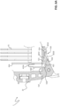
- FIGS 7-10 show the behaviour of the switch pole 1 during an opening manoeuvre of the switching device 100.
- Figure 7 shows the switch pole with the movable contacts 321 coupled to the fixed contacts 311 (closed condition of the switching device). In this situation, a current can flow along the switch pole between the pole terminals 7, 8 and no electric arcs develop between the electric contacts 311, 321.
- the movable contacts 321 are moved away from the fixed contacts 311.
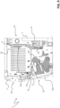
- the high energy ionization effects of the air (dielectric medium) between the electric contacts leads to the generation of high-pressure hot gases, which cross the arc-extinguishing area 4 mainly moving towards the top wall 25 (the path of the hot gases at this stage of the opening manoeuvre is schematically represented by the solid arrows of figure 8 ).
- the additional arc-breaking element 42 has the terminal edge 421A and the protruding tab 421D of the first portion 421, which are located in proximity of contact area 3, so that the movable contacts 321 pass at a very short distance from these latter, while moving away from the fixed contacts 311. Electric arcs are thus forced to pass through the first and second plate portions 421, 422 of the additional arc-breaking element 42.
- hot gases are progressively conveyed to the front wall 23 and, subsequently, to the top wall 25 of the insulating gases 2, which additionally favors the stripping the electric arcs towards the additional arc-breaking element 42 (the path of the hot gases at this stage of the opening manoeuvre is schematically represented by the solid arrows of figure 9 ).
- substantially all arc breaking plates are involved in the quenching action of electric arcs, thereby allowing a more uniform utilization of the arc chamber. Less mechanical and thermal stresses are therefore generated into the arc chamber with a consequent prolonged lifetime of this latter.
- the fluid of the hot gases through the switch pole is greatly improved, thus further contributing to stripping the electric arcs throughout the arc chamber and improving the cooling of the movable contacts of the switch pole.
- the present invention relates also to a low voltage switching device 100 comprising at least one low voltage switch pole 1 as previously described.
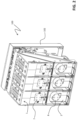
- a three-pole low voltage circuit breaker 100 comprising three low voltage switch poles 1 (i.e. circuit breaker poles) is shown.
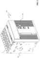
- the insulating casing 2 of each switch pole 1 is made of two half shells, and the poles 1 are positioned side by side in a supporting a containing structure having rigid flanks 102, as well as a cover 101. From suitable windows in the front wall 23 of the insulating casing 2 of each switch pole 1, connecting elements 323 protrude outside for connection with a driving mechanism (not shown).
- the general structure of such low voltage circuit breaker 100 is, in general, well known in the art and therefore it will be not described in more details, for the sake of brevity.
Landscapes
- Arc-Extinguishing Devices That Are Switches (AREA)
Claims (14)
- Schaltpol (1) für eine Niederspannungs-Schaltvorrichtung (100), umfassend:- ein isolierendes Gehäuse (2), das einen Innenraum mit einem Kontaktbereich (3) und einem Lichtbogen-Löschbereich (4) des Schaltpols definiert,- eine Anordnung fester Kontakte (31) und eine Anordnung beweglicher Kontakte (32), die in dem Kontaktbereich (3) positioniert sind und einen oder mehrere feste Kontakte (311) beziehungsweise einen oder mehrere bewegliche Kontakte (321) beinhalten, die miteinander gekoppelt oder ungekoppelt sein können,- eine Lichtbogenkammer (40), die in dem Lichtbogen-Löschbereich (4) positioniert ist und eine Mehrzahl von lichtbogenunterbrechenden Platten (41, 41A) umfasst,wobei das isolierende Gehäuse (2) eine isolierende Wand (5) umfasst, die den Kontaktbereich (3) teilweise von dem Lichtbogen-Löschbereich (4) trennt, wobei die isolierende Wand in dem Innenraum in einer gegenüberliegenden Position in Bezug auf die Anordnung fester Kontakte (31) angeordnet ist und sich von einer Außenwand (23) des isolierenden Gehäuses (2) zu der Anordnung fester Kontakte (31) hin erstreckt,wobei die isolierende Wand (5) einen Kanal (51) beinhaltet, der durch die isolierende Wand verläuft und den Kontaktbereich (3) mit dem Lichtbogen-Löschbereich (4) verbindet, dadurch gekennzeichnet, dass er ein zusätzliches lichtbogenunterbrechendes Element (42) umfasst, das an der isolierenden Wand (5) verankert und teilweise in den Kanal (51) eingesetzt ist, wobei das zusätzliche lichtbogenunterbrechende Element (42) in elektrischer Verbindung mit einer endständigen lichtbogenunterbrechenden Platte (41A) steht, die an einer von der Anordnung fester Kontakte (31) entfernten Position im Vergleich zu den anderen lichtbogenunterbrechenden Platten (41) der Lichtbogenkammer angeordnet ist.
- Schaltpol nach Anspruch 1, dadurch gekennzeichnet, dass das zusätzliche lichtbogenunterbrechende Element (42) einen ersten Plattenabschnitt (421) umfasst, der in den Kanal (51) eingesetzt ist und sich entlang der isolierenden Wand (5) erstreckt.
- Schaltpol nach Anspruch 2, dadurch gekennzeichnet, dass der erste Plattenabschnitt (421) einen endständigen Rand (421A) umfasst, der zu dem Kontaktbereich (3) hin freiliegt.
- Schaltpol nach einem der Ansprüche 2 bis 3, dadurch gekennzeichnet, dass der erste Plattenabschnitt (421) eine Öffnung (421C) umfasst, um den Durchtritt heißer Gase durch den Kanal (51) zu begünstigen.
- Schaltpol nach einem der Ansprüche 2 bis 4, dadurch gekennzeichnet, dass der erste Plattenabschnitt (421) eine hervorstehende Nase (421D) aufweist, die zu dem Kontaktbereich (3) hin ausgerichtet ist und zu dem Kontaktbereich hin freiliegt.
- Schaltpol nach einem der Ansprüche 2 bis 5, dadurch gekennzeichnet, dass der erste Plattenabschnitt (421) ein Paar seitlicher Vorsprünge (421B) aufweist, die zu entsprechenden Verankerungsoberflächen des Kanals (51) passen.
- Schaltpol nach einem der vorhergehenden Ansprüche, dadurch gekennzeichnet, dass das zusätzliche lichtbogenunterbrechende Element (42) einen zweiten Plattenabschnitt (422) umfasst, der durch den Kanal (51) verläuft und von der isolierenden Wand (51) hervorsteht, sich über den Lichtbogen-Löschbereich (4) erstreckend.
- Schaltpol nach Anspruch 7, dadurch gekennzeichnet, dass der zweite Plattenabschnitt (422) ein gefalztes Ende (422A) umfasst, das mit dem endständigen lichtbogenunterbrechenden Element (41A) gekoppelt ist.
- Schaltpol nach Anspruch 8, dadurch gekennzeichnet, dass das gefalzte Ende (422A) ein umgekehrtes U-Profil aufweist.
- Schaltpol nach einem der vorhergehenden Ansprüche, dadurch gekennzeichnet, dass das isolierende Gehäuse (2) eine vordere und eine gegenüberliegende hintere Wand (23, 24) aufweist, wobei die endständige lichtbogenunterbrechende Platte (41A) an der vorderen Wand (23) angeordnet ist, wobei die Anordnung fester Kontakte (31) an der hinteren Wand (24) angeordnet ist.
- Schaltpol nach einem der vorhergehenden Ansprüche, dadurch gekennzeichnet, dass das endständige lichtbogenunterbrechende Element (41A) an einer zu dem Kontaktbereich (3) nahen Position im Vergleich zu den anderen lichtbogenunterbrechenden Platten (41) der Lichtbogenkammer angeordnet ist.
- Schaltpol nach einem der vorhergehenden Ansprüche, dadurch gekennzeichnet, dass die Lichtbogenkammer (4) eine isolierende Kapselung (43) umfasst, die entnehmbar an dem isolierenden Gehäuse (2) befestigt sein kann, wobei die lichtbogenunterbrechenden Platten (41, 41A) an der isolierenden Kapselung (43) befestigt sind.
- Schaltpol nach einem der vorhergehenden Ansprüche, dadurch gekennzeichnet, dass die isolierende Wand (5) integral mit einer vorderen Wand (23) und einander gegenüberliegenden Seitenwänden (21, 22) des isolierenden Gehäuses (2) ist und sich von der vorderen Wand (23) zu der Anordnung fester Kontakte (31) hin erstreckt.
- Niederspannungs-Schaltvorrichtung (100), dadurch gekennzeichnet, dass sie einen Schaltpol (1) nach einem der vorhergehenden Ansprüche umfasst.
Priority Applications (4)
| Application Number | Priority Date | Filing Date | Title |
|---|---|---|---|
| ES21206994T ES2991365T3 (es) | 2021-11-08 | 2021-11-08 | Polo de conmutación de baja tensión |
| EP21206994.2A EP4177920B1 (de) | 2021-11-08 | 2021-11-08 | Niederspannungsschalterpol |
| CN202211394092.7A CN116092844A (zh) | 2021-11-08 | 2022-11-08 | 低压开关极 |
| US17/982,640 US12087525B2 (en) | 2021-11-08 | 2022-11-08 | Low voltage switch pole |
Applications Claiming Priority (1)
| Application Number | Priority Date | Filing Date | Title |
|---|---|---|---|
| EP21206994.2A EP4177920B1 (de) | 2021-11-08 | 2021-11-08 | Niederspannungsschalterpol |
Publications (2)
| Publication Number | Publication Date |
|---|---|
| EP4177920A1 EP4177920A1 (de) | 2023-05-10 |
| EP4177920B1 true EP4177920B1 (de) | 2024-06-26 |
Family
ID=78592532
Family Applications (1)
| Application Number | Title | Priority Date | Filing Date |
|---|---|---|---|
| EP21206994.2A Active EP4177920B1 (de) | 2021-11-08 | 2021-11-08 | Niederspannungsschalterpol |
Country Status (4)
| Country | Link |
|---|---|
| US (1) | US12087525B2 (de) |
| EP (1) | EP4177920B1 (de) |
| CN (1) | CN116092844A (de) |
| ES (1) | ES2991365T3 (de) |
Family Cites Families (15)
| Publication number | Priority date | Publication date | Assignee | Title |
|---|---|---|---|---|
| FR2624650B1 (fr) | 1987-12-10 | 1990-04-06 | Merlin Gerin | Disjoncteur multipolaire a boitier moule de calibre eleve |
| US5899323A (en) | 1998-05-07 | 1999-05-04 | Eaton Corporation | Electrical switching apparatus with contact finger guide |
| FR2778788B1 (fr) | 1998-05-12 | 2000-07-13 | Schneider Electric Ind Sa | Disjoncteur dont une phase au moins est constituee par plusieurs compartiments polaires connectes en parallele |
| DE10219558B4 (de) | 2002-04-26 | 2004-08-26 | Siemens Ag | Elektrischer Leistungsschalter mit einer Anschlussschiene und einem Lichtbogenhorn |
| AT509277A1 (de) * | 2008-03-05 | 2011-07-15 | Moeller Gebaeudeautomation Gmbh | Schaltgerät |
| US8817443B2 (en) * | 2010-04-14 | 2014-08-26 | Abb Spa | Residual current protection device |
| EP2463878A1 (de) * | 2010-12-07 | 2012-06-13 | Eaton Industries GmbH | Schalter mit Löschkammer |
| JP5568049B2 (ja) | 2011-04-07 | 2014-08-06 | 株式会社日立産機システム | 回路遮断器 |
| US9124090B2 (en) | 2013-08-29 | 2015-09-01 | Siemens Industry, Inc. | Combined circuit breaker and DC power supply apparatus, systems, and methods |
| KR101521545B1 (ko) | 2013-10-07 | 2015-05-19 | 한국전기연구원 | 고압 직류 전류 차단 장치 및 방법 |
| ES2645855T3 (es) * | 2015-01-23 | 2017-12-11 | Abb S.P.A. | Polo interruptor de bajo voltaje |
| KR101733276B1 (ko) | 2015-03-13 | 2017-05-24 | 공주대학교 산학협력단 | 직류용 회로 차단 장치 |
| KR20170108657A (ko) | 2016-03-18 | 2017-09-27 | 엘에스산전 주식회사 | 직류 차단기 |
| US10211003B1 (en) * | 2017-11-22 | 2019-02-19 | Carling Technologies, Inc. | Single pole DC circuit breaker with bi-directional arc chamber |
| KR102108146B1 (ko) * | 2017-12-27 | 2020-05-11 | 엘에스일렉트릭(주) | 직류 차단기 |
-
2021
- 2021-11-08 ES ES21206994T patent/ES2991365T3/es active Active
- 2021-11-08 EP EP21206994.2A patent/EP4177920B1/de active Active
-
2022
- 2022-11-08 CN CN202211394092.7A patent/CN116092844A/zh active Pending
- 2022-11-08 US US17/982,640 patent/US12087525B2/en active Active
Also Published As
| Publication number | Publication date |
|---|---|
| CN116092844A (zh) | 2023-05-09 |
| EP4177920A1 (de) | 2023-05-10 |
| ES2991365T3 (es) | 2024-12-03 |
| US12087525B2 (en) | 2024-09-10 |
| US20230145656A1 (en) | 2023-05-11 |
Similar Documents
| Publication | Publication Date | Title |
|---|---|---|
| US9715979B2 (en) | Low voltage switch pole | |
| CN1770351A (zh) | 用于模制外壳的电路断路器的灭弧器组件 | |
| CN1235364A (zh) | 至少有一相是由几个电极隔室并联连接形成的电路断路器 | |
| KR200393296Y1 (ko) | 배선용 차단기의 소호장치 | |
| CN117334539A (zh) | 一种低压塑壳断路器的触头灭弧系统 | |
| US12237131B2 (en) | Device for door and phase segregation in molded case circuit breakers | |
| US12087525B2 (en) | Low voltage switch pole | |
| US12362113B2 (en) | Low voltage switch pole | |
| EP4336531B1 (de) | Niederspannungsschaltpol mit einem lichtbogenunterbrechungselement mit einer abdeckung für heisse gase mit einem plattenelement und einem durchbruch | |
| EP4489047A1 (de) | Druckluftschalter | |
| CN112017924A (zh) | 一种断路器的灭弧系统 | |
| CN213304049U (zh) | 一种断路器的触头灭弧装置 | |
| CN213184178U (zh) | 触头机构和开关电器 | |
| EP3872826B1 (de) | Verbesserte schaltvorrichtung | |
| EP4439603A1 (de) | Niederspannungsschaltpol mit schutzplattenanordnung | |
| US20240266127A1 (en) | Low-voltage switch pole | |
| CN219203078U (zh) | 一种用于塑壳断路器的零飞弧罩 | |
| EP4435815A1 (de) | Schaltvorrichtung für elektrische mittelspannungssysteme | |
| CN213026022U (zh) | 一种优化的灭弧装置 | |
| CN217485324U (zh) | 一种开关 | |
| CN120833986A (zh) | 用于电气系统的开关设备 | |
| KR100926646B1 (ko) | 분전반용 과전류 차단기 | |
| CN113972116A (zh) | 触头机构和开关电器 | |
| CN110098095A (zh) | 气吹式低压灭弧装置及断路器 |
Legal Events
| Date | Code | Title | Description |
|---|---|---|---|
| PUAI | Public reference made under article 153(3) epc to a published international application that has entered the european phase |
Free format text: ORIGINAL CODE: 0009012 |
|
| STAA | Information on the status of an ep patent application or granted ep patent |
Free format text: STATUS: THE APPLICATION HAS BEEN PUBLISHED |
|
| AK | Designated contracting states |
Kind code of ref document: A1 Designated state(s): AL AT BE BG CH CY CZ DE DK EE ES FI FR GB GR HR HU IE IS IT LI LT LU LV MC MK MT NL NO PL PT RO RS SE SI SK SM TR |
|
| STAA | Information on the status of an ep patent application or granted ep patent |
Free format text: STATUS: REQUEST FOR EXAMINATION WAS MADE |
|
| 17P | Request for examination filed |
Effective date: 20231017 |
|
| RBV | Designated contracting states (corrected) |
Designated state(s): AL AT BE BG CH CY CZ DE DK EE ES FI FR GB GR HR HU IE IS IT LI LT LU LV MC MK MT NL NO PL PT RO RS SE SI SK SM TR |
|
| GRAP | Despatch of communication of intention to grant a patent |
Free format text: ORIGINAL CODE: EPIDOSNIGR1 |
|
| STAA | Information on the status of an ep patent application or granted ep patent |
Free format text: STATUS: GRANT OF PATENT IS INTENDED |
|
| INTG | Intention to grant announced |
Effective date: 20240321 |
|
| GRAS | Grant fee paid |
Free format text: ORIGINAL CODE: EPIDOSNIGR3 |
|
| GRAA | (expected) grant |
Free format text: ORIGINAL CODE: 0009210 |
|
| STAA | Information on the status of an ep patent application or granted ep patent |
Free format text: STATUS: THE PATENT HAS BEEN GRANTED |
|
| AK | Designated contracting states |
Kind code of ref document: B1 Designated state(s): AL AT BE BG CH CY CZ DE DK EE ES FI FR GB GR HR HU IE IS IT LI LT LU LV MC MK MT NL NO PL PT RO RS SE SI SK SM TR |
|
| REG | Reference to a national code |
Ref country code: GB Ref legal event code: FG4D |
|
| REG | Reference to a national code |
Ref country code: CH Ref legal event code: EP |
|
| REG | Reference to a national code |
Ref country code: DE Ref legal event code: R096 Ref document number: 602021014776 Country of ref document: DE |
|
| PG25 | Lapsed in a contracting state [announced via postgrant information from national office to epo] |
Ref country code: BG Free format text: LAPSE BECAUSE OF FAILURE TO SUBMIT A TRANSLATION OF THE DESCRIPTION OR TO PAY THE FEE WITHIN THE PRESCRIBED TIME-LIMIT Effective date: 20240626 |
|
| PG25 | Lapsed in a contracting state [announced via postgrant information from national office to epo] |
Ref country code: FI Free format text: LAPSE BECAUSE OF FAILURE TO SUBMIT A TRANSLATION OF THE DESCRIPTION OR TO PAY THE FEE WITHIN THE PRESCRIBED TIME-LIMIT Effective date: 20240626 Ref country code: HR Free format text: LAPSE BECAUSE OF FAILURE TO SUBMIT A TRANSLATION OF THE DESCRIPTION OR TO PAY THE FEE WITHIN THE PRESCRIBED TIME-LIMIT Effective date: 20240626 |
|
| REG | Reference to a national code |
Ref country code: LT Ref legal event code: MG9D |
|
| PG25 | Lapsed in a contracting state [announced via postgrant information from national office to epo] |
Ref country code: GR Free format text: LAPSE BECAUSE OF FAILURE TO SUBMIT A TRANSLATION OF THE DESCRIPTION OR TO PAY THE FEE WITHIN THE PRESCRIBED TIME-LIMIT Effective date: 20240927 |
|
| PG25 | Lapsed in a contracting state [announced via postgrant information from national office to epo] |
Ref country code: LV Free format text: LAPSE BECAUSE OF FAILURE TO SUBMIT A TRANSLATION OF THE DESCRIPTION OR TO PAY THE FEE WITHIN THE PRESCRIBED TIME-LIMIT Effective date: 20240626 |
|
| REG | Reference to a national code |
Ref country code: NL Ref legal event code: MP Effective date: 20240626 |
|
| PG25 | Lapsed in a contracting state [announced via postgrant information from national office to epo] |
Ref country code: NO Free format text: LAPSE BECAUSE OF FAILURE TO SUBMIT A TRANSLATION OF THE DESCRIPTION OR TO PAY THE FEE WITHIN THE PRESCRIBED TIME-LIMIT Effective date: 20240926 Ref country code: LV Free format text: LAPSE BECAUSE OF FAILURE TO SUBMIT A TRANSLATION OF THE DESCRIPTION OR TO PAY THE FEE WITHIN THE PRESCRIBED TIME-LIMIT Effective date: 20240626 Ref country code: HR Free format text: LAPSE BECAUSE OF FAILURE TO SUBMIT A TRANSLATION OF THE DESCRIPTION OR TO PAY THE FEE WITHIN THE PRESCRIBED TIME-LIMIT Effective date: 20240626 Ref country code: GR Free format text: LAPSE BECAUSE OF FAILURE TO SUBMIT A TRANSLATION OF THE DESCRIPTION OR TO PAY THE FEE WITHIN THE PRESCRIBED TIME-LIMIT Effective date: 20240927 Ref country code: FI Free format text: LAPSE BECAUSE OF FAILURE TO SUBMIT A TRANSLATION OF THE DESCRIPTION OR TO PAY THE FEE WITHIN THE PRESCRIBED TIME-LIMIT Effective date: 20240626 Ref country code: BG Free format text: LAPSE BECAUSE OF FAILURE TO SUBMIT A TRANSLATION OF THE DESCRIPTION OR TO PAY THE FEE WITHIN THE PRESCRIBED TIME-LIMIT Effective date: 20240626 Ref country code: RS Free format text: LAPSE BECAUSE OF FAILURE TO SUBMIT A TRANSLATION OF THE DESCRIPTION OR TO PAY THE FEE WITHIN THE PRESCRIBED TIME-LIMIT Effective date: 20240926 |
|
| PG25 | Lapsed in a contracting state [announced via postgrant information from national office to epo] |
Ref country code: NL Free format text: LAPSE BECAUSE OF FAILURE TO SUBMIT A TRANSLATION OF THE DESCRIPTION OR TO PAY THE FEE WITHIN THE PRESCRIBED TIME-LIMIT Effective date: 20240626 |
|
| REG | Reference to a national code |
Ref country code: AT Ref legal event code: MK05 Ref document number: 1698421 Country of ref document: AT Kind code of ref document: T Effective date: 20240626 |
|
| PG25 | Lapsed in a contracting state [announced via postgrant information from national office to epo] |
Ref country code: NL Free format text: LAPSE BECAUSE OF FAILURE TO SUBMIT A TRANSLATION OF THE DESCRIPTION OR TO PAY THE FEE WITHIN THE PRESCRIBED TIME-LIMIT Effective date: 20240626 |
|
| REG | Reference to a national code |
Ref country code: ES Ref legal event code: FG2A Ref document number: 2991365 Country of ref document: ES Kind code of ref document: T3 Effective date: 20241203 |
|
| PG25 | Lapsed in a contracting state [announced via postgrant information from national office to epo] |
Ref country code: PT Free format text: LAPSE BECAUSE OF FAILURE TO SUBMIT A TRANSLATION OF THE DESCRIPTION OR TO PAY THE FEE WITHIN THE PRESCRIBED TIME-LIMIT Effective date: 20241028 |
|
| PG25 | Lapsed in a contracting state [announced via postgrant information from national office to epo] |
Ref country code: PT Free format text: LAPSE BECAUSE OF FAILURE TO SUBMIT A TRANSLATION OF THE DESCRIPTION OR TO PAY THE FEE WITHIN THE PRESCRIBED TIME-LIMIT Effective date: 20241028 |
|
| PG25 | Lapsed in a contracting state [announced via postgrant information from national office to epo] |
Ref country code: PL Free format text: LAPSE BECAUSE OF FAILURE TO SUBMIT A TRANSLATION OF THE DESCRIPTION OR TO PAY THE FEE WITHIN THE PRESCRIBED TIME-LIMIT Effective date: 20240626 |
|
| PG25 | Lapsed in a contracting state [announced via postgrant information from national office to epo] |
Ref country code: EE Free format text: LAPSE BECAUSE OF FAILURE TO SUBMIT A TRANSLATION OF THE DESCRIPTION OR TO PAY THE FEE WITHIN THE PRESCRIBED TIME-LIMIT Effective date: 20240626 |
|
| PG25 | Lapsed in a contracting state [announced via postgrant information from national office to epo] |
Ref country code: IS Free format text: LAPSE BECAUSE OF FAILURE TO SUBMIT A TRANSLATION OF THE DESCRIPTION OR TO PAY THE FEE WITHIN THE PRESCRIBED TIME-LIMIT Effective date: 20241026 Ref country code: AT Free format text: LAPSE BECAUSE OF FAILURE TO SUBMIT A TRANSLATION OF THE DESCRIPTION OR TO PAY THE FEE WITHIN THE PRESCRIBED TIME-LIMIT Effective date: 20240626 |
|
| PG25 | Lapsed in a contracting state [announced via postgrant information from national office to epo] |
Ref country code: CZ Free format text: LAPSE BECAUSE OF FAILURE TO SUBMIT A TRANSLATION OF THE DESCRIPTION OR TO PAY THE FEE WITHIN THE PRESCRIBED TIME-LIMIT Effective date: 20240626 |
|
| PG25 | Lapsed in a contracting state [announced via postgrant information from national office to epo] |
Ref country code: RO Free format text: LAPSE BECAUSE OF FAILURE TO SUBMIT A TRANSLATION OF THE DESCRIPTION OR TO PAY THE FEE WITHIN THE PRESCRIBED TIME-LIMIT Effective date: 20240626 Ref country code: SK Free format text: LAPSE BECAUSE OF FAILURE TO SUBMIT A TRANSLATION OF THE DESCRIPTION OR TO PAY THE FEE WITHIN THE PRESCRIBED TIME-LIMIT Effective date: 20240626 |
|
| PG25 | Lapsed in a contracting state [announced via postgrant information from national office to epo] |
Ref country code: SM Free format text: LAPSE BECAUSE OF FAILURE TO SUBMIT A TRANSLATION OF THE DESCRIPTION OR TO PAY THE FEE WITHIN THE PRESCRIBED TIME-LIMIT Effective date: 20240626 |
|
| PG25 | Lapsed in a contracting state [announced via postgrant information from national office to epo] |
Ref country code: SM Free format text: LAPSE BECAUSE OF FAILURE TO SUBMIT A TRANSLATION OF THE DESCRIPTION OR TO PAY THE FEE WITHIN THE PRESCRIBED TIME-LIMIT Effective date: 20240626 Ref country code: SK Free format text: LAPSE BECAUSE OF FAILURE TO SUBMIT A TRANSLATION OF THE DESCRIPTION OR TO PAY THE FEE WITHIN THE PRESCRIBED TIME-LIMIT Effective date: 20240626 Ref country code: RO Free format text: LAPSE BECAUSE OF FAILURE TO SUBMIT A TRANSLATION OF THE DESCRIPTION OR TO PAY THE FEE WITHIN THE PRESCRIBED TIME-LIMIT Effective date: 20240626 Ref country code: PL Free format text: LAPSE BECAUSE OF FAILURE TO SUBMIT A TRANSLATION OF THE DESCRIPTION OR TO PAY THE FEE WITHIN THE PRESCRIBED TIME-LIMIT Effective date: 20240626 Ref country code: IS Free format text: LAPSE BECAUSE OF FAILURE TO SUBMIT A TRANSLATION OF THE DESCRIPTION OR TO PAY THE FEE WITHIN THE PRESCRIBED TIME-LIMIT Effective date: 20241026 Ref country code: EE Free format text: LAPSE BECAUSE OF FAILURE TO SUBMIT A TRANSLATION OF THE DESCRIPTION OR TO PAY THE FEE WITHIN THE PRESCRIBED TIME-LIMIT Effective date: 20240626 Ref country code: CZ Free format text: LAPSE BECAUSE OF FAILURE TO SUBMIT A TRANSLATION OF THE DESCRIPTION OR TO PAY THE FEE WITHIN THE PRESCRIBED TIME-LIMIT Effective date: 20240626 Ref country code: AT Free format text: LAPSE BECAUSE OF FAILURE TO SUBMIT A TRANSLATION OF THE DESCRIPTION OR TO PAY THE FEE WITHIN THE PRESCRIBED TIME-LIMIT Effective date: 20240626 |
|
| REG | Reference to a national code |
Ref country code: DE Ref legal event code: R097 Ref document number: 602021014776 Country of ref document: DE |
|
| PG25 | Lapsed in a contracting state [announced via postgrant information from national office to epo] |
Ref country code: DK Free format text: LAPSE BECAUSE OF FAILURE TO SUBMIT A TRANSLATION OF THE DESCRIPTION OR TO PAY THE FEE WITHIN THE PRESCRIBED TIME-LIMIT Effective date: 20240626 |
|
| PLBE | No opposition filed within time limit |
Free format text: ORIGINAL CODE: 0009261 |
|
| STAA | Information on the status of an ep patent application or granted ep patent |
Free format text: STATUS: NO OPPOSITION FILED WITHIN TIME LIMIT |
|
| 26N | No opposition filed |
Effective date: 20250327 |
|
| REG | Reference to a national code |
Ref country code: CH Ref legal event code: PL |
|
| PG25 | Lapsed in a contracting state [announced via postgrant information from national office to epo] |
Ref country code: MC Free format text: LAPSE BECAUSE OF FAILURE TO SUBMIT A TRANSLATION OF THE DESCRIPTION OR TO PAY THE FEE WITHIN THE PRESCRIBED TIME-LIMIT Effective date: 20240626 |
|
| PG25 | Lapsed in a contracting state [announced via postgrant information from national office to epo] |
Ref country code: LU Free format text: LAPSE BECAUSE OF NON-PAYMENT OF DUE FEES Effective date: 20241108 |
|
| REG | Reference to a national code |
Ref country code: CH Ref legal event code: PL |
|
| PG25 | Lapsed in a contracting state [announced via postgrant information from national office to epo] |
Ref country code: CH Free format text: LAPSE BECAUSE OF NON-PAYMENT OF DUE FEES Effective date: 20241130 |
|
| REG | Reference to a national code |
Ref country code: BE Ref legal event code: MM Effective date: 20241130 |
|
| PG25 | Lapsed in a contracting state [announced via postgrant information from national office to epo] |
Ref country code: SE Free format text: LAPSE BECAUSE OF FAILURE TO SUBMIT A TRANSLATION OF THE DESCRIPTION OR TO PAY THE FEE WITHIN THE PRESCRIBED TIME-LIMIT Effective date: 20240626 |
|
| PG25 | Lapsed in a contracting state [announced via postgrant information from national office to epo] |
Ref country code: BE Free format text: LAPSE BECAUSE OF NON-PAYMENT OF DUE FEES Effective date: 20241130 |
|
| PG25 | Lapsed in a contracting state [announced via postgrant information from national office to epo] |
Ref country code: IE Free format text: LAPSE BECAUSE OF NON-PAYMENT OF DUE FEES Effective date: 20241108 |
|
| PGFP | Annual fee paid to national office [announced via postgrant information from national office to epo] |
Ref country code: DE Payment date: 20251119 Year of fee payment: 5 |
|
| PGFP | Annual fee paid to national office [announced via postgrant information from national office to epo] |
Ref country code: GB Payment date: 20251121 Year of fee payment: 5 |
|
| PGFP | Annual fee paid to national office [announced via postgrant information from national office to epo] |
Ref country code: IT Payment date: 20251125 Year of fee payment: 5 |
|
| PGFP | Annual fee paid to national office [announced via postgrant information from national office to epo] |
Ref country code: FR Payment date: 20251126 Year of fee payment: 5 |
|
| PGFP | Annual fee paid to national office [announced via postgrant information from national office to epo] |
Ref country code: ES Payment date: 20251229 Year of fee payment: 5 |
|
| PG25 | Lapsed in a contracting state [announced via postgrant information from national office to epo] |
Ref country code: HU Free format text: LAPSE BECAUSE OF FAILURE TO SUBMIT A TRANSLATION OF THE DESCRIPTION OR TO PAY THE FEE WITHIN THE PRESCRIBED TIME-LIMIT; INVALID AB INITIO Effective date: 20211108 |
|
| PG25 | Lapsed in a contracting state [announced via postgrant information from national office to epo] |
Ref country code: CY Free format text: LAPSE BECAUSE OF FAILURE TO SUBMIT A TRANSLATION OF THE DESCRIPTION OR TO PAY THE FEE WITHIN THE PRESCRIBED TIME-LIMIT; INVALID AB INITIO Effective date: 20211108 |