EP4178010A1 - Empilement d'éléments de batterie et son procédé de fabrication - Google Patents
Empilement d'éléments de batterie et son procédé de fabrication Download PDFInfo
- Publication number
- EP4178010A1 EP4178010A1 EP22206208.5A EP22206208A EP4178010A1 EP 4178010 A1 EP4178010 A1 EP 4178010A1 EP 22206208 A EP22206208 A EP 22206208A EP 4178010 A1 EP4178010 A1 EP 4178010A1
- Authority
- EP
- European Patent Office
- Prior art keywords
- battery cell
- resin layer
- cell stack
- resin
- fibers
- Prior art date
- Legal status (The legal status is an assumption and is not a legal conclusion. Google has not performed a legal analysis and makes no representation as to the accuracy of the status listed.)
- Pending
Links
Images

Classifications
-
- H—ELECTRICITY
- H01—ELECTRIC ELEMENTS
- H01M—PROCESSES OR MEANS, e.g. BATTERIES, FOR THE DIRECT CONVERSION OF CHEMICAL ENERGY INTO ELECTRICAL ENERGY
- H01M50/00—Constructional details or processes of manufacture of the non-active parts of electrochemical cells other than fuel cells, e.g. hybrid cells
- H01M50/20—Mountings; Secondary casings or frames; Racks, modules or packs; Suspension devices; Shock absorbers; Transport or carrying devices; Holders
- H01M50/289—Mountings; Secondary casings or frames; Racks, modules or packs; Suspension devices; Shock absorbers; Transport or carrying devices; Holders characterised by spacing elements or positioning means within frames, racks or packs
- H01M50/293—Mountings; Secondary casings or frames; Racks, modules or packs; Suspension devices; Shock absorbers; Transport or carrying devices; Holders characterised by spacing elements or positioning means within frames, racks or packs characterised by the material
-
- H—ELECTRICITY
- H01—ELECTRIC ELEMENTS
- H01M—PROCESSES OR MEANS, e.g. BATTERIES, FOR THE DIRECT CONVERSION OF CHEMICAL ENERGY INTO ELECTRICAL ENERGY
- H01M50/00—Constructional details or processes of manufacture of the non-active parts of electrochemical cells other than fuel cells, e.g. hybrid cells
- H01M50/20—Mountings; Secondary casings or frames; Racks, modules or packs; Suspension devices; Shock absorbers; Transport or carrying devices; Holders
- H01M50/204—Racks, modules or packs for multiple batteries or multiple cells
-
- C—CHEMISTRY; METALLURGY
- C08—ORGANIC MACROMOLECULAR COMPOUNDS; THEIR PREPARATION OR CHEMICAL WORKING-UP; COMPOSITIONS BASED THEREON
- C08J—WORKING-UP; GENERAL PROCESSES OF COMPOUNDING; AFTER-TREATMENT NOT COVERED BY SUBCLASSES C08B, C08C, C08F, C08G or C08H
- C08J5/00—Manufacture of articles or shaped materials containing macromolecular substances
- C08J5/12—Bonding of a preformed macromolecular material to the same or other solid material such as metal, glass, leather, e.g. using adhesives
-
- C—CHEMISTRY; METALLURGY
- C09—DYES; PAINTS; POLISHES; NATURAL RESINS; ADHESIVES; COMPOSITIONS NOT OTHERWISE PROVIDED FOR; APPLICATIONS OF MATERIALS NOT OTHERWISE PROVIDED FOR
- C09J—ADHESIVES; NON-MECHANICAL ASPECTS OF ADHESIVE PROCESSES IN GENERAL; ADHESIVE PROCESSES NOT PROVIDED FOR ELSEWHERE; USE OF MATERIALS AS ADHESIVES
- C09J5/00—Adhesive processes in general; Adhesive processes not provided for elsewhere, e.g. relating to primers
-
- H—ELECTRICITY
- H01—ELECTRIC ELEMENTS
- H01M—PROCESSES OR MEANS, e.g. BATTERIES, FOR THE DIRECT CONVERSION OF CHEMICAL ENERGY INTO ELECTRICAL ENERGY
- H01M10/00—Secondary cells; Manufacture thereof
- H01M10/04—Construction or manufacture in general
-
- H—ELECTRICITY
- H01—ELECTRIC ELEMENTS
- H01M—PROCESSES OR MEANS, e.g. BATTERIES, FOR THE DIRECT CONVERSION OF CHEMICAL ENERGY INTO ELECTRICAL ENERGY
- H01M10/00—Secondary cells; Manufacture thereof
- H01M10/05—Accumulators with non-aqueous electrolyte
- H01M10/052—Li-accumulators
-
- H—ELECTRICITY
- H01—ELECTRIC ELEMENTS
- H01M—PROCESSES OR MEANS, e.g. BATTERIES, FOR THE DIRECT CONVERSION OF CHEMICAL ENERGY INTO ELECTRICAL ENERGY
- H01M10/00—Secondary cells; Manufacture thereof
- H01M10/60—Heating or cooling; Temperature control
- H01M10/65—Means for temperature control structurally associated with the cells
- H01M10/658—Means for temperature control structurally associated with the cells by thermal insulation or shielding
-
- H—ELECTRICITY
- H01—ELECTRIC ELEMENTS
- H01M—PROCESSES OR MEANS, e.g. BATTERIES, FOR THE DIRECT CONVERSION OF CHEMICAL ENERGY INTO ELECTRICAL ENERGY
- H01M4/00—Electrodes
- H01M4/02—Electrodes composed of, or comprising, active material
- H01M4/13—Electrodes for accumulators with non-aqueous electrolyte, e.g. for lithium-accumulators; Processes of manufacture thereof
- H01M4/133—Electrodes based on carbonaceous material, e.g. graphite-intercalation compounds or CFx
-
- H—ELECTRICITY
- H01—ELECTRIC ELEMENTS
- H01M—PROCESSES OR MEANS, e.g. BATTERIES, FOR THE DIRECT CONVERSION OF CHEMICAL ENERGY INTO ELECTRICAL ENERGY
- H01M50/00—Constructional details or processes of manufacture of the non-active parts of electrochemical cells other than fuel cells, e.g. hybrid cells
- H01M50/10—Primary casings; Jackets or wrappings
- H01M50/102—Primary casings; Jackets or wrappings characterised by their shape or physical structure
- H01M50/103—Primary casings; Jackets or wrappings characterised by their shape or physical structure prismatic or rectangular
-
- H—ELECTRICITY
- H01—ELECTRIC ELEMENTS
- H01M—PROCESSES OR MEANS, e.g. BATTERIES, FOR THE DIRECT CONVERSION OF CHEMICAL ENERGY INTO ELECTRICAL ENERGY
- H01M50/00—Constructional details or processes of manufacture of the non-active parts of electrochemical cells other than fuel cells, e.g. hybrid cells
- H01M50/10—Primary casings; Jackets or wrappings
- H01M50/102—Primary casings; Jackets or wrappings characterised by their shape or physical structure
- H01M50/105—Pouches or flexible bags
-
- H—ELECTRICITY
- H01—ELECTRIC ELEMENTS
- H01M—PROCESSES OR MEANS, e.g. BATTERIES, FOR THE DIRECT CONVERSION OF CHEMICAL ENERGY INTO ELECTRICAL ENERGY
- H01M50/00—Constructional details or processes of manufacture of the non-active parts of electrochemical cells other than fuel cells, e.g. hybrid cells
- H01M50/10—Primary casings; Jackets or wrappings
- H01M50/116—Primary casings; Jackets or wrappings characterised by the material
- H01M50/124—Primary casings; Jackets or wrappings characterised by the material having a layered structure
- H01M50/1245—Primary casings; Jackets or wrappings characterised by the material having a layered structure characterised by the external coating on the casing
-
- H—ELECTRICITY
- H01—ELECTRIC ELEMENTS
- H01M—PROCESSES OR MEANS, e.g. BATTERIES, FOR THE DIRECT CONVERSION OF CHEMICAL ENERGY INTO ELECTRICAL ENERGY
- H01M50/00—Constructional details or processes of manufacture of the non-active parts of electrochemical cells other than fuel cells, e.g. hybrid cells
- H01M50/10—Primary casings; Jackets or wrappings
- H01M50/14—Primary casings; Jackets or wrappings for protecting against damage caused by external factors
- H01M50/143—Fireproof; Explosion-proof
-
- H—ELECTRICITY
- H01—ELECTRIC ELEMENTS
- H01M—PROCESSES OR MEANS, e.g. BATTERIES, FOR THE DIRECT CONVERSION OF CHEMICAL ENERGY INTO ELECTRICAL ENERGY
- H01M50/00—Constructional details or processes of manufacture of the non-active parts of electrochemical cells other than fuel cells, e.g. hybrid cells
- H01M50/20—Mountings; Secondary casings or frames; Racks, modules or packs; Suspension devices; Shock absorbers; Transport or carrying devices; Holders
- H01M50/204—Racks, modules or packs for multiple batteries or multiple cells
- H01M50/207—Racks, modules or packs for multiple batteries or multiple cells characterised by their shape
- H01M50/211—Racks, modules or packs for multiple batteries or multiple cells characterised by their shape adapted for pouch cells
-
- H—ELECTRICITY
- H01—ELECTRIC ELEMENTS
- H01M—PROCESSES OR MEANS, e.g. BATTERIES, FOR THE DIRECT CONVERSION OF CHEMICAL ENERGY INTO ELECTRICAL ENERGY
- H01M50/00—Constructional details or processes of manufacture of the non-active parts of electrochemical cells other than fuel cells, e.g. hybrid cells
- H01M50/20—Mountings; Secondary casings or frames; Racks, modules or packs; Suspension devices; Shock absorbers; Transport or carrying devices; Holders
- H01M50/233—Mountings; Secondary casings or frames; Racks, modules or packs; Suspension devices; Shock absorbers; Transport or carrying devices; Holders characterised by physical properties of casings or racks, e.g. dimensions
- H01M50/24—Mountings; Secondary casings or frames; Racks, modules or packs; Suspension devices; Shock absorbers; Transport or carrying devices; Holders characterised by physical properties of casings or racks, e.g. dimensions adapted for protecting batteries from their environment, e.g. from corrosion
-
- H—ELECTRICITY
- H01—ELECTRIC ELEMENTS
- H01M—PROCESSES OR MEANS, e.g. BATTERIES, FOR THE DIRECT CONVERSION OF CHEMICAL ENERGY INTO ELECTRICAL ENERGY
- H01M50/00—Constructional details or processes of manufacture of the non-active parts of electrochemical cells other than fuel cells, e.g. hybrid cells
- H01M50/20—Mountings; Secondary casings or frames; Racks, modules or packs; Suspension devices; Shock absorbers; Transport or carrying devices; Holders
- H01M50/233—Mountings; Secondary casings or frames; Racks, modules or packs; Suspension devices; Shock absorbers; Transport or carrying devices; Holders characterised by physical properties of casings or racks, e.g. dimensions
- H01M50/242—Mountings; Secondary casings or frames; Racks, modules or packs; Suspension devices; Shock absorbers; Transport or carrying devices; Holders characterised by physical properties of casings or racks, e.g. dimensions adapted for protecting batteries against vibrations, collision impact or swelling
-
- H—ELECTRICITY
- H01—ELECTRIC ELEMENTS
- H01M—PROCESSES OR MEANS, e.g. BATTERIES, FOR THE DIRECT CONVERSION OF CHEMICAL ENERGY INTO ELECTRICAL ENERGY
- H01M50/00—Constructional details or processes of manufacture of the non-active parts of electrochemical cells other than fuel cells, e.g. hybrid cells
- H01M50/20—Mountings; Secondary casings or frames; Racks, modules or packs; Suspension devices; Shock absorbers; Transport or carrying devices; Holders
- H01M50/262—Mountings; Secondary casings or frames; Racks, modules or packs; Suspension devices; Shock absorbers; Transport or carrying devices; Holders with fastening means, e.g. locks
- H01M50/264—Mountings; Secondary casings or frames; Racks, modules or packs; Suspension devices; Shock absorbers; Transport or carrying devices; Holders with fastening means, e.g. locks for cells or batteries, e.g. straps, tie rods or peripheral frames
-
- H—ELECTRICITY
- H01—ELECTRIC ELEMENTS
- H01M—PROCESSES OR MEANS, e.g. BATTERIES, FOR THE DIRECT CONVERSION OF CHEMICAL ENERGY INTO ELECTRICAL ENERGY
- H01M50/00—Constructional details or processes of manufacture of the non-active parts of electrochemical cells other than fuel cells, e.g. hybrid cells
- H01M50/50—Current conducting connections for cells or batteries
- H01M50/543—Terminals
- H01M50/547—Terminals characterised by the disposition of the terminals on the cells
- H01M50/55—Terminals characterised by the disposition of the terminals on the cells on the same side of the cell
-
- C—CHEMISTRY; METALLURGY
- C09—DYES; PAINTS; POLISHES; NATURAL RESINS; ADHESIVES; COMPOSITIONS NOT OTHERWISE PROVIDED FOR; APPLICATIONS OF MATERIALS NOT OTHERWISE PROVIDED FOR
- C09J—ADHESIVES; NON-MECHANICAL ASPECTS OF ADHESIVE PROCESSES IN GENERAL; ADHESIVE PROCESSES NOT PROVIDED FOR ELSEWHERE; USE OF MATERIALS AS ADHESIVES
- C09J2203/00—Applications of adhesives in processes or use of adhesives in the form of films or foils
- C09J2203/33—Applications of adhesives in processes or use of adhesives in the form of films or foils for batteries or fuel cells
-
- C—CHEMISTRY; METALLURGY
- C09—DYES; PAINTS; POLISHES; NATURAL RESINS; ADHESIVES; COMPOSITIONS NOT OTHERWISE PROVIDED FOR; APPLICATIONS OF MATERIALS NOT OTHERWISE PROVIDED FOR
- C09J—ADHESIVES; NON-MECHANICAL ASPECTS OF ADHESIVE PROCESSES IN GENERAL; ADHESIVE PROCESSES NOT PROVIDED FOR ELSEWHERE; USE OF MATERIALS AS ADHESIVES
- C09J2301/00—Additional features of adhesives in the form of films or foils
- C09J2301/30—Additional features of adhesives in the form of films or foils characterized by the chemical, physicochemical or physical properties of the adhesive or the carrier
- C09J2301/302—Additional features of adhesives in the form of films or foils characterized by the chemical, physicochemical or physical properties of the adhesive or the carrier the adhesive being pressure-sensitive, i.e. tacky at temperatures inferior to 30°C
-
- C—CHEMISTRY; METALLURGY
- C09—DYES; PAINTS; POLISHES; NATURAL RESINS; ADHESIVES; COMPOSITIONS NOT OTHERWISE PROVIDED FOR; APPLICATIONS OF MATERIALS NOT OTHERWISE PROVIDED FOR
- C09J—ADHESIVES; NON-MECHANICAL ASPECTS OF ADHESIVE PROCESSES IN GENERAL; ADHESIVE PROCESSES NOT PROVIDED FOR ELSEWHERE; USE OF MATERIALS AS ADHESIVES
- C09J2421/00—Presence of unspecified rubber
-
- Y—GENERAL TAGGING OF NEW TECHNOLOGICAL DEVELOPMENTS; GENERAL TAGGING OF CROSS-SECTIONAL TECHNOLOGIES SPANNING OVER SEVERAL SECTIONS OF THE IPC; TECHNICAL SUBJECTS COVERED BY FORMER USPC CROSS-REFERENCE ART COLLECTIONS [XRACs] AND DIGESTS
- Y02—TECHNOLOGIES OR APPLICATIONS FOR MITIGATION OR ADAPTATION AGAINST CLIMATE CHANGE
- Y02E—REDUCTION OF GREENHOUSE GAS [GHG] EMISSIONS, RELATED TO ENERGY GENERATION, TRANSMISSION OR DISTRIBUTION
- Y02E60/00—Enabling technologies; Technologies with a potential or indirect contribution to GHG emissions mitigation
- Y02E60/10—Energy storage using batteries
Definitions
- the present invention relates to a battery cell stack and a method of manufacturing the same.
- the secondary battery may include a nickel-cadmium battery, a nickel-metal hydride battery, a nickel-hydrogen battery, and a lithium secondary battery.
- the lithium secondary batteries have a high operating voltage and excellent energy density characteristics per unit weight, they are used as a power source for portable electronic devices. Alternately, a plurality of lithium secondary batteries are connected in series, and then used in a high-output hybrid vehicle or an electric vehicle.
- a plurality of secondary batteries When used in the high-output hybrid vehicle or electric vehicle, in order to increase capacity and output of the secondary battery, a plurality of secondary batteries may be connected and used in a form of one battery module and a battery pack.
- various fastening parts or cooling equipment are required. However, these fastening parts or cooling equipment cause an increase in manufacturing costs while increasing volume and weight thereof, and also lead to a decrease in output in proportion to the increased volume and weight.
- a method of manufacturing a cell stack forming a battery module by attaching a tape type adhesive to cell surfaces is also used.
- processes and equipment for inputting the tape and removing a release paper are complicated, and waste such as release paper may be generated in large quantities during manufacturing the battery module.
- An object of embodiments of the present invention is to provide a battery cell stack, to which a resin layer including a solvent-free adhesive suitable for improving structural stability, reliability and reworkability is applied, while simplifying materials and processes necessary to manufacture the cell stack, and a method of manufacturing the same.
- a battery cell stack including: a plurality of battery cells; and a resin layer which is wholly or partially in contact with an outer surface of at least one of the plurality of battery cells.
- the resin layer may be formed of a resin layer composition including a solvent-free adhesive.
- the resin layer may have a peel strength of 1,000 gf/in to 3,000 gf/in measured according to ASTM D3330.
- the resin layer may have a shear strength of 20 kgf/sq-in to 100 kgf/sq-in measured according to ASTM D1002.
- the solvent-free adhesive may include one or more selected from the group consisting of an ethylene vinyl acetate resin, polyamide resin, fatty acid polyamide resin, polyester resin, polyurethane resin, polyolefin resin, styrene resin and rubber resin.
- the solvent-free adhesive may be a pressure sensitive adhesive (PSA).
- PSA pressure sensitive adhesive
- the resin layer may have a viscosity of 2,000 cps to 18,500 cps at 160 °C.
- the resin layer may have a softening point of 60 °C to 140 °C.
- the resin layer may have a withstand voltage of 10.0 to 30.0 kV/mm measured according to ASTM D149.
- the battery cell stack may further include a functional layer disposed between the plurality of battery cells, and the resin layer may be wholly or partially in contact with the functional layer.
- the functional layer may include one or more selected from the group consisting of aerogel, talc, kaolin, alumina, feldspar, pyrophyllite, sericite, mica, elvan, bentonite, sepiolite, diatomite, perlite, fumed silica, silica, glass bubble, glass bead, magnesium hydroxide, calcium carbide, glass fibers, glass wool, rock wool, ceramic wool, nylon, aramid fibers, carbon fibers, polypropylene fibers, polyethylene fibers, polyester fibers, polyurethane fibers, acrylic fibers, polyvinyl chloride acetate fibers, and rayon fibers.
- a method of manufacturing a battery cell stack which includes: applying a resin layer including a solvent-free adhesive to an outer surface of a battery cell so as to bring it wholly or partially into contact therewith; and stacking an additional battery cell on the resin layer.
- the resin layer may have a peel strength of 1,000 gf/in to 3,000 gf/in measured according to ASTM D3330.
- the resin layer may have a shear strength of 20 kgf/sq-in to 100 kgf/sq-in measured according to ASTM D1002.
- the resin layer may be applied by spray coating or slot die coating.
- the application of the resin layer may be performed at 140 to 180 °C.
- the resin layer may have a thickness of 0.01 to 0.10 mm.
- a resin layer including a solvent-free adhesive by applying a resin layer including a solvent-free adhesive, it is possible to manufacture a battery cell stack with improved structural stability and reliability, while simplifying the required materials and processes.
- resin layer refers to a layer including a resin component.
- the resin layer may be an adhesion layer or an adhesive layer.
- solvent-free adhesive refers to a thermoplastic adhesive which is made of a thermoplastic resin without using a solvent or other solvents, and is capable of being melted at a melting point or more, and then solidified by cooling.
- the solvent-free adhesive is a hot-melt adhesive which is applied to a material to be adhered in a liquid state at a high temperature, and exhibits an adhesive force by dissipating heat to the surface of the material to be adhered and surroundings after compression, thus to be cooled and solidified within a few seconds.
- PSA pressure sensitive adhesive
- a battery cell stack according to an embodiment of the present invention may be widely used in various devices requiring electricity storage, such as an energy storage system (ESS) as well as a vehicle.
- ESS energy storage system
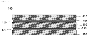
- FIGS. 1 to 3 are schematic views of a battery cell stack according to exemplary embodiments, respectively.
- a battery cell stack 100 may include a plurality of battery cells 110 and a resin layer 120 wholly or partially in contact with an outer surface of at least one of the plurality of battery cells.
- the battery cell stack 100 is configured by stacking the plurality of battery cells 110.
- the battery cells 110 may be vertically erected and stacked in a left-and-right direction (i.e., in a horizontal direction), but may be horizontally laid down and stacked in an up- and-down direction (i.e., in a vertical direction) as necessary.
- the battery cell 110 is a general battery cell.
- the battery cell 110 according to an embodiment of the present invention may be configured in a form in which an electrode assembly and an electrolyte are accommodated in a pouch.
- the electrode assembly includes a plurality of electrode plates and electrode tabs, and is accommodated in the pouch.
- the electrode plate includes a cathode plate and an anode plate, and the electrode assembly may be configured in a stacked form so that the cathode plate and the anode plate have wide surfaces facing each other with a separator interposed therebetween.
- the battery cells 110 may be fixed to each other by the resin layer 120.
- the resin layer 120 may be formed on the outer surfaces of the battery cells 110 to be mutually fixed to the battery cells 110 adjacent thereto. That is, the battery cells 110 may be fixed to each other due to the resin layer 120 formed between the battery cell 110 and the battery cell 110.
- the resin layer 120 may be formed as an adhesive layer.
- the resin layer 120 may be wholly or partially applied to the surface of the battery cell 110. As the battery cells 110 and the resin layers 120 are repeatedly disposed, the battery cells 110 may be wholly or partially fixed to each other through the resin layer 120.
- the resin layer 120 includes a solvent-free adhesive material, preferably a pressure sensitive adhesive (PSA) material, and more preferably a solvent-free or hot-melt coatable pressure sensitive adhesive.
- PSA pressure sensitive adhesive
- the solvent-free adhesive may include one or more selected from the group consisting of an ethylene vinyl acetate resin, polyamide resin, fatty acid polyamide resin, polyester resin, polyurethane resin, polyolefin resin, styrene resin and rubber resin.
- the resin layer may include a flame retardant. Since the resin layer including the solvent-free adhesive may be applied by spray coating or slot die coating, in order to exhibit effective flame retardancy while simultaneously exhibiting suitable properties, the flame retardant preferably includes at least one of a phosphorus-based flame retardant and a nitrogen-based flame retardant.
- the phosphorus-based flame retardant may include a phosphate compound, a phosphonate compound, a phosphinate compound, a phosphine oxide compound, a phosphazene compound, or metal salts thereof and the like. These compounds may be used alone or in combination of two or more thereof.
- the phosphorus-based flame retardant may include diphenyl phosphate, diaryl phosphate, triphenyl phosphate, tricresyl phosphate, trizyrenyl phosphate, tri(2,6-dimethylphenyl)phosphate, tri(2,4,6-trimethylphenyl)phosphate, tri(2,4-di-tert-butylphenyl)phosphate, tri(2,6-dimethylphenyl)phosphate, bisphenol-A bis(diphenylphosphate), resorcinol bis(diphenylphosphate), resorcinol bis[bis(2,6-dimethylphenyl)phosphate], resorcinol bis[bis(2,4-di-tert-butylphenyl)phosphate], hydroquinone bis[bis(2,6-dimethylphenyl)phosphate], hydroquinone bis[bis(2,4-di-tert-butylphenyl)phosphate], an oli
- the nitrogen-based flame retardant may include melamine and melamine derivatives. These may be used alone or in combination of two or more thereof.
- the nitrogen-based flame retardant may include melamine, melamine phosphate, melamine cyanurate, etc., but it is not limited thereto. These may be applied alone or in a form of a mixture of two or more thereof.
- the flame retardant may be included in an amount of 10 to 50 parts by weight (“wt. parts") based on 100 wt. parts of the resin layer.
- wt. parts 10 to 50 parts by weight
- the contents of the above-described phosphorus-based flame retardant and the nitrogen-based flame retardant are preferably added and used alone or in the same proportion as each other in a sum of both retardants. If the proportion of the flame retardant is less than 10 wt. parts, the flame retardancy is insufficient, whereas if it exceeds 50 wt. parts, physical properties such as an adhesive force or workability when applying the resin layer may be deteriorated.
- the resin layer 120 preferably has a peel strength of about 1,000 gf/in to 3,000 gf/in measured according to ASTM D3330.
- the peel strength is 1,000 gf/in or more, excellent adhesive force to various materials forming the battery cell stack 100 may be exhibited, and the relative flow of the battery cells 110 may be prevented, thus to improve the stability of the battery module, whereas if it is less than 1,000 gf/in, there may be problems in that adhesion to the cell stack is deteriorated in the process of stacking the cells or an alignment between the cells is misaligned due to micro-vibrations in the process or micro-vibrations and accelerations in the shuttle process.
- the application workability of the resin layer 120 may be maintained at an appropriate temperature, whereas if it exceeds 3,000 gf/in, reworkability may be reduced, and it becomes difficult to disassemble the battery cell stack when recycling, as well as, when a composition of the resin layer 120 ("resin layer 120 composition") is used in a solvent-free adhesive method, since the application should be performed at a high temperature, a damage due to heat may be induced on the surface of the battery cell.
- the resin layer 120 may have a shear strength of about 20 kgf/sq-in to 100 kgf/sq-in measured according to ASTM D1002.
- the shear strength is 20 kgf/sq-in or more, impact resistance of the battery cell stack 100 may be improved, whereas if it is less than 20 kgf/sq-in, there may be problems in that adhesion to the cell stack is deteriorated in the process of stacking the cells or the alignment between the cells is misaligned due to micro-vibrations in the process or micro-vibrations and accelerations in the shuttle process.
- the application workability of the resin layer 120 may be maintained at an appropriate temperature, whereas if it exceeds 100 kgf/sq-in, reworkability may be reduced, and it becomes difficult to disassemble the battery cell stack when recycling, as well as, when the resin layer 120 composition is used in a solvent-free adhesive method, since the application should be performed at a high temperature, a damage due to heat may be induced on the surface of the battery cell.
- the resin layer 120 may have a viscosity of about 2,000 to 18,500 cps at 160 °C. In the above viscosity range, when applying the resin layer 120 to the battery cell 110 before curing, workability necessary for the process may be improved, and the stability and reliability of the battery cell stack 100 may be secured after curing.
- the resin layer 120 may have a softening point of about 60 to 140 °C, and preferably about 80 to 105 °C. In the above softening point range, when a defect occurs during manufacturing the battery cell stack 100, a rework is easily performed and a damage to the cell may be minimized, as well as the resin layer 120 may be easily removed when recycling the battery cell stack 100. Whereas, if the softening point is less than 60°C, the viscosity of the resin layer 120 composition is low, and re-liquefaction may occur in the resin layer 120 due to heat generated from the battery cell 110, and thereby causing the impact resistance of the battery cell stack 100 to be deteriorated.
- the softening point exceeds 140°C, when applying the resin layer, nozzle clogging of an applicator or scattering of the resin layer 120 composition may occur, and a damage due to heat may occur in the battery cell 110 when the resin layer 120 is re-liquefied.
- the resin layer 120 may have a withstand voltage of 10.0 kV/mm to 30 kV/mm or less measured according to ASTM D149.
- the withstand voltage is 10.0 kV/mm or more, performances of the battery cell stack 100 may be maintained and stability may be secured.
- the resin layer 120 exhibits excellent insulation, and it is not particularly limited, but considering the adhesive force of the resin layer 120 including the solvent-free adhesive, it is preferable that the withstand voltage is 30 kV/mm or less.
- the resin layer 120 may be formed in a form of a relatively thin layer compared to the battery cell 110.
- the resin layer 120 may have a thickness within a range of 0.01 to 0.10 mm, or 0.02 to 0.08 mm, or about 0.03 to 0.05 mm, for example. If the resin layer 120 is less than 0.01 mm, a fixing force between the battery cells 110 is weakened to cause a reduction in the stability of the battery cell stack 100, whereas if it exceeds 0.10 mm, the thickness of the battery cell stack 100 may be increased, which may be disadvantageous in terms of battery module design.
- the thickness may be a thickness of the thinnest portion, a thickness of the thickest portion, or an average thickness of the resin layer 120.
- the resin layer 120 may also be formed in a form of filling an inner space of a battery case including the battery cell stack 100.
- the battery cell 110 may exist in a state of being inserted into the resin layer 120.
- the battery cell stack 100 may further include a functional layer 130 disposed between the plurality of battery cells 110, wherein the resin layer 120 may be wholly or partially in contact with the functional layer 130.
- the functional layer 130 may be an insulation layer for improving electrical insulation, or may be an insulation layer for improving thermal insulation.
- the functional layer 130 may include a binder resin and/or particles.
- the functional layer 130 may be formed by applying it to the surface of the battery cell 110, or may be formed separately in the resin layer 120.
- the functional layer 130 may be intended to block heat generated from the battery cell 110, or may be intended to prevent ignition of the battery.
- the functional layer 130 may include one or more selected from the group consisting of aerogel, talc, kaolin, alumina, feldspar, pyrophyllite, sericite, mica, elvan, bentonite, sepiolite, diatomite, perlite, fumed silica, silica, glass bubble, glass bead, magnesium hydroxide, calcium carbide, glass fibers, glass wool, rock wool, ceramic wool, nylon, aramid fibers, carbon fibers, polypropylene fibers, polyethylene fibers, polyester fibers, polyurethane fibers, acrylic fibers, polyvinyl chloride acetate fibers, and rayon fibers.
- a method of manufacturing a battery cell stack according to exemplary embodiments of the present invention may include: applying a resin layer including a solvent-free adhesive to an outer surface of a battery cell so as to bring it wholly or partially into contact therewith; and stacking an additional battery cell on the resin layer.
- the battery cell, the resin layer, and the solvent-free adhesive are the same as those described above, and therefore will not be described in detail.
- the resin layer may be heated inside a tank of the applicator and pumped to a nozzle to be applied to the outer surface of the battery cell.
- the resin layer according to the present invention includes the solvent-free adhesive, it may be applied by a spray coating or slot die coating.
- the application of the resin layer may be performed at 140 °C to 180 °C.
- an additional battery cell is stacked on the resin layer.
- the stacking of the additional battery cells may be continuously performed after the application of the resin layer.
- the method of manufacturing a battery cell stack significantly reduces the process steps and time compared to the conventional process using the tape method, and thus productivity of the battery cell stack may be greatly increased.
- An aluminum pouch (material to be adhered) used for manufacturing the battery cell was cut into a width of about 10 mm, then a heated resin layer composition was applied to a PET surface of the pouch washed with acetone to a thickness of 0.03 mm using an applicator, thus to form a resin layer.
- rubber resin as a basic resin paraffin wax as a wax component, terpene resin as a tackifier resin, polybdenum as a plasticizer, calcium carbonate as a filler, and phenyl- ⁇ -naphthylamine as an antioxidant were used, and physical properties of the resin layers were controlled by varying addition amounts of these components (Examples 1 to 5 and Comparative Examples 1 to 4).
- the resin layers of Examples 1 to 5 and Comparative Examples 1 to 5 were applied to a battery cell whose surface was washed with acetone to a thickness of 0.03 mm, respectively. After stacking another battery cell on the applied resin layer, the resin layer was cured to prepare a battery cell stack.
- Comparative Example 5 which contains a water-soluble adhesive, it was found that the application state was good, but reworkability was lowered, and insulation properties of the resin layer was easily destroyed when applying a certain impact.
Landscapes
- Chemical & Material Sciences (AREA)
- Chemical Kinetics & Catalysis (AREA)
- Electrochemistry (AREA)
- General Chemical & Material Sciences (AREA)
- Engineering & Computer Science (AREA)
- Manufacturing & Machinery (AREA)
- Organic Chemistry (AREA)
- Materials Engineering (AREA)
- Health & Medical Sciences (AREA)
- Medicinal Chemistry (AREA)
- Polymers & Plastics (AREA)
- Laminated Bodies (AREA)
- Sealing Battery Cases Or Jackets (AREA)
Applications Claiming Priority (2)
| Application Number | Priority Date | Filing Date | Title |
|---|---|---|---|
| KR20210153335 | 2021-11-09 | ||
| KR1020220128041A KR102831591B1 (ko) | 2021-11-09 | 2022-10-06 | 배터리 셀 적층체 및 이의 제조방법 |
Publications (1)
| Publication Number | Publication Date |
|---|---|
| EP4178010A1 true EP4178010A1 (fr) | 2023-05-10 |
Family
ID=84332304
Family Applications (1)
| Application Number | Title | Priority Date | Filing Date |
|---|---|---|---|
| EP22206208.5A Pending EP4178010A1 (fr) | 2021-11-09 | 2022-11-08 | Empilement d'éléments de batterie et son procédé de fabrication |
Country Status (4)
| Country | Link |
|---|---|
| US (1) | US20230143120A1 (fr) |
| EP (1) | EP4178010A1 (fr) |
| KR (1) | KR20250105596A (fr) |
| CN (1) | CN116111248A (fr) |
Citations (2)
| Publication number | Priority date | Publication date | Assignee | Title |
|---|---|---|---|---|
| US20200006726A1 (en) * | 2018-06-29 | 2020-01-02 | Lg Chem, Ltd. | Battery Module Including Unit Body |
| KR20210020665A (ko) * | 2019-08-16 | 2021-02-24 | 주식회사 엘지화학 | 배터리 모듈 |
Family Cites Families (4)
| Publication number | Priority date | Publication date | Assignee | Title |
|---|---|---|---|---|
| EP3419082B1 (fr) * | 2016-04-01 | 2021-06-16 | LG Chem, Ltd. | Module de batterie |
| KR20210000551A (ko) * | 2019-06-25 | 2021-01-05 | 주식회사 엘지화학 | 전지 팩 및 이를 포함하는 디바이스 |
| WO2021183493A1 (fr) * | 2020-03-12 | 2021-09-16 | Rogers Corporation | Feuille multicouche de gestion thermique destinée à une batterie |
| KR20230118078A (ko) * | 2020-12-04 | 2023-08-10 | 로저스코포레이션 | 열 폭주 방지용 다층 시트 |
-
2022
- 2022-11-08 EP EP22206208.5A patent/EP4178010A1/fr active Pending
- 2022-11-08 US US17/982,593 patent/US20230143120A1/en active Pending
- 2022-11-09 CN CN202211399619.5A patent/CN116111248A/zh active Pending
-
2025
- 2025-06-30 KR KR1020250087277A patent/KR20250105596A/ko active Pending
Patent Citations (3)
| Publication number | Priority date | Publication date | Assignee | Title |
|---|---|---|---|---|
| US20200006726A1 (en) * | 2018-06-29 | 2020-01-02 | Lg Chem, Ltd. | Battery Module Including Unit Body |
| KR20200002349A (ko) | 2018-06-29 | 2020-01-08 | 주식회사 엘지화학 | 단위체를 포함하는 배터리 모듈 |
| KR20210020665A (ko) * | 2019-08-16 | 2021-02-24 | 주식회사 엘지화학 | 배터리 모듈 |
Also Published As
| Publication number | Publication date |
|---|---|
| CN116111248A (zh) | 2023-05-12 |
| KR20250105596A (ko) | 2025-07-08 |
| US20230143120A1 (en) | 2023-05-11 |
Similar Documents
| Publication | Publication Date | Title |
|---|---|---|
| KR20230067506A (ko) | 배터리 셀 적층체 및 이의 제조방법 | |
| JP7412417B2 (ja) | リチウムイオン電池スタック | |
| JP4771003B1 (ja) | 電池パックおよび電池パックの製造方法 | |
| KR102831591B1 (ko) | 배터리 셀 적층체 및 이의 제조방법 | |
| WO2016080696A1 (fr) | Plaque de refroidissement pour batterie secondaire et module de batterie secondaire muni de celle-ci | |
| CN111757915A (zh) | 树脂组合物和包含其的电池模块 | |
| KR101772800B1 (ko) | 이차전지 | |
| CN115799738A (zh) | 用于具有改进的热性能的电池组外壳的杂化复合材料系统 | |
| US20260094921A1 (en) | Method for Manufacturing Battery Cell Stack | |
| EP4178012B1 (fr) | Empilement d'éléments de batterie et son procédé de fabrication | |
| EP4178010A1 (fr) | Empilement d'éléments de batterie et son procédé de fabrication | |
| KR20130024596A (ko) | 안전성이 향상된 이차전지 | |
| WO2021025443A1 (fr) | Compartiment de batterie pour batterie secondaire et batterie secondaire de type poche | |
| CN117239324A (zh) | 用于具有改进的热性能的电池外壳和盖的复合材料系统 | |
| EP4183851A1 (fr) | Film adhésif pour bornes métalliques, borne métallique comportant le film adhésif pour bornes métalliques, dispositif de stockage d'électricité utilisant ledit film adhésif pour bornes métalliques et procédé de fabrication de dispositif de stockage d'électricité | |
| KR102818014B1 (ko) | 전기차용 파우치형 배터리 셀 간 접착테이프 | |
| KR101834561B1 (ko) | 유체 반응형 마감 테이프 | |
| KR102659188B1 (ko) | 배터리 모듈용 점착 조성물 및 이를 포함하는 배터리 모듈용 외곽 커버 필름 | |
| KR20220107606A (ko) | 배터리 셀 점착용 양면 테이프 및 상기 테이프에 의하여 부착된 복수의 배터리 셀을 포함하는 배터리 모듈 | |
| WO2021206306A1 (fr) | Fil d'électrode, son procédé de production, et batterie secondaire de type poche | |
| US20250323351A1 (en) | Thermal runaway prevention film and method for manufacturing the same | |
| JP7827817B2 (ja) | 電池パック及び電動車両 | |
| EP4293797B1 (fr) | Batterie secondaire de type poche ayant d'excellentes propriétés d'isolation et de dissipation de chaleur | |
| US20240304917A1 (en) | Method of manufacturing battery module | |
| KR102940426B1 (ko) | 전극 리드, 그의 제조 방법 및 파우치 형 이차 전지 |
Legal Events
| Date | Code | Title | Description |
|---|---|---|---|
| PUAI | Public reference made under article 153(3) epc to a published international application that has entered the european phase |
Free format text: ORIGINAL CODE: 0009012 |
|
| STAA | Information on the status of an ep patent application or granted ep patent |
Free format text: STATUS: REQUEST FOR EXAMINATION WAS MADE |
|
| 17P | Request for examination filed |
Effective date: 20221108 |
|
| AK | Designated contracting states |
Kind code of ref document: A1 Designated state(s): AL AT BE BG CH CY CZ DE DK EE ES FI FR GB GR HR HU IE IS IT LI LT LU LV MC ME MK MT NL NO PL PT RO RS SE SI SK SM TR |
|
| STAA | Information on the status of an ep patent application or granted ep patent |
Free format text: STATUS: EXAMINATION IS IN PROGRESS |
|
| 17Q | First examination report despatched |
Effective date: 20250102 |
|
| REG | Reference to a national code |
Ref country code: DE Ref legal event code: R079 Free format text: PREVIOUS MAIN CLASS: H01M0010653000 Ipc: C08J0005120000 Ref country code: DE Ref legal event code: R079 Ref document number: 602022036778 Country of ref document: DE Free format text: PREVIOUS MAIN CLASS: H01M0010653000 Ipc: C08J0005120000 |
|
| GRAP | Despatch of communication of intention to grant a patent |
Free format text: ORIGINAL CODE: EPIDOSNIGR1 |
|
| STAA | Information on the status of an ep patent application or granted ep patent |
Free format text: STATUS: GRANT OF PATENT IS INTENDED |
|
| RIC1 | Information provided on ipc code assigned before grant |
Ipc: C08J 5/12 20060101AFI20251201BHEP Ipc: C09J 5/00 20060101ALI20251201BHEP Ipc: H01M 50/124 20210101ALI20251201BHEP Ipc: H01M 50/14 20210101ALI20251201BHEP Ipc: H01M 50/143 20210101ALI20251201BHEP Ipc: H01M 50/105 20210101ALI20251201BHEP Ipc: H01M 50/211 20210101ALI20251201BHEP Ipc: H01M 50/24 20210101ALI20251201BHEP Ipc: H01M 10/658 20140101ALI20251201BHEP Ipc: H01M 50/242 20210101ALI20251201BHEP Ipc: H01M 50/264 20210101ALI20251201BHEP |
|
| INTG | Intention to grant announced |
Effective date: 20251210 |
|
| GRAS | Grant fee paid |
Free format text: ORIGINAL CODE: EPIDOSNIGR3 |
|
| GRAA | (expected) grant |
Free format text: ORIGINAL CODE: 0009210 |
|
| STAA | Information on the status of an ep patent application or granted ep patent |
Free format text: STATUS: THE PATENT HAS BEEN GRANTED |