EP4178055A1 - Hochspannungsgleichstromsysteme - Google Patents
Hochspannungsgleichstromsysteme Download PDFInfo
- Publication number
- EP4178055A1 EP4178055A1 EP22205870.3A EP22205870A EP4178055A1 EP 4178055 A1 EP4178055 A1 EP 4178055A1 EP 22205870 A EP22205870 A EP 22205870A EP 4178055 A1 EP4178055 A1 EP 4178055A1
- Authority
- EP
- European Patent Office
- Prior art keywords
- generator
- switch module
- rectifier
- sense
- overcurrent
- Prior art date
- Legal status (The legal status is an assumption and is not a legal conclusion. Google has not performed a legal analysis and makes no representation as to the accuracy of the status listed.)
- Pending
Links
Images
Classifications
-
- H—ELECTRICITY
- H02—GENERATION; CONVERSION OR DISTRIBUTION OF ELECTRIC POWER
- H02H—EMERGENCY PROTECTIVE CIRCUIT ARRANGEMENTS
- H02H7/00—Emergency protective circuit arrangements specially adapted for specific types of electric machines or apparatus or for sectionalised protection of cable or line systems, and effecting automatic switching in the event of an undesired change from normal working conditions
- H02H7/10—Emergency protective circuit arrangements specially adapted for specific types of electric machines or apparatus or for sectionalised protection of cable or line systems, and effecting automatic switching in the event of an undesired change from normal working conditions for converters; for rectifiers
- H02H7/12—Emergency protective circuit arrangements specially adapted for specific types of electric machines or apparatus or for sectionalised protection of cable or line systems, and effecting automatic switching in the event of an undesired change from normal working conditions for converters; for rectifiers for static converters or rectifiers
- H02H7/125—Emergency protective circuit arrangements specially adapted for specific types of electric machines or apparatus or for sectionalised protection of cable or line systems, and effecting automatic switching in the event of an undesired change from normal working conditions for converters; for rectifiers for static converters or rectifiers for rectifiers
- H02H7/1257—Emergency protective circuit arrangements specially adapted for specific types of electric machines or apparatus or for sectionalised protection of cable or line systems, and effecting automatic switching in the event of an undesired change from normal working conditions for converters; for rectifiers for static converters or rectifiers for rectifiers responsive to short circuit or wrong polarity in output circuit
-
- H—ELECTRICITY
- H02—GENERATION; CONVERSION OR DISTRIBUTION OF ELECTRIC POWER
- H02H—EMERGENCY PROTECTIVE CIRCUIT ARRANGEMENTS
- H02H7/00—Emergency protective circuit arrangements specially adapted for specific types of electric machines or apparatus or for sectionalised protection of cable or line systems, and effecting automatic switching in the event of an undesired change from normal working conditions
- H02H7/10—Emergency protective circuit arrangements specially adapted for specific types of electric machines or apparatus or for sectionalised protection of cable or line systems, and effecting automatic switching in the event of an undesired change from normal working conditions for converters; for rectifiers
- H02H7/12—Emergency protective circuit arrangements specially adapted for specific types of electric machines or apparatus or for sectionalised protection of cable or line systems, and effecting automatic switching in the event of an undesired change from normal working conditions for converters; for rectifiers for static converters or rectifiers
- H02H7/125—Emergency protective circuit arrangements specially adapted for specific types of electric machines or apparatus or for sectionalised protection of cable or line systems, and effecting automatic switching in the event of an undesired change from normal working conditions for converters; for rectifiers for static converters or rectifiers for rectifiers
-
- B—PERFORMING OPERATIONS; TRANSPORTING
- B64—AIRCRAFT; AVIATION; COSMONAUTICS
- B64D—EQUIPMENT FOR FITTING IN OR TO AIRCRAFT; FLIGHT SUITS; PARACHUTES; ARRANGEMENT OR MOUNTING OF POWER PLANTS OR PROPULSION TRANSMISSIONS IN AIRCRAFT
- B64D41/00—Power installations for auxiliary purposes
-
- H—ELECTRICITY
- H02—GENERATION; CONVERSION OR DISTRIBUTION OF ELECTRIC POWER
- H02H—EMERGENCY PROTECTIVE CIRCUIT ARRANGEMENTS
- H02H1/00—Details of emergency protective circuit arrangements
- H02H1/0007—Details of emergency protective circuit arrangements concerning the detecting means
-
- H—ELECTRICITY
- H02—GENERATION; CONVERSION OR DISTRIBUTION OF ELECTRIC POWER
- H02H—EMERGENCY PROTECTIVE CIRCUIT ARRANGEMENTS
- H02H3/00—Emergency protective circuit arrangements for automatic disconnection directly responsive to an undesired change from normal electric working condition with or without subsequent reconnection ; integrated protection
- H02H3/02—Details
- H02H3/021—Details concerning the disconnection itself, e.g. at a particular instant, particularly at zero value of current, disconnection in a predetermined order
- H02H3/023—Details concerning the disconnection itself, e.g. at a particular instant, particularly at zero value of current, disconnection in a predetermined order by short-circuiting
-
- H—ELECTRICITY
- H02—GENERATION; CONVERSION OR DISTRIBUTION OF ELECTRIC POWER
- H02H—EMERGENCY PROTECTIVE CIRCUIT ARRANGEMENTS
- H02H7/00—Emergency protective circuit arrangements specially adapted for specific types of electric machines or apparatus or for sectionalised protection of cable or line systems, and effecting automatic switching in the event of an undesired change from normal working conditions
- H02H7/06—Emergency protective circuit arrangements specially adapted for specific types of electric machines or apparatus or for sectionalised protection of cable or line systems, and effecting automatic switching in the event of an undesired change from normal working conditions for dynamo-electric generators; for synchronous capacitors
-
- H—ELECTRICITY
- H02—GENERATION; CONVERSION OR DISTRIBUTION OF ELECTRIC POWER
- H02H—EMERGENCY PROTECTIVE CIRCUIT ARRANGEMENTS
- H02H7/00—Emergency protective circuit arrangements specially adapted for specific types of electric machines or apparatus or for sectionalised protection of cable or line systems, and effecting automatic switching in the event of an undesired change from normal working conditions
- H02H7/10—Emergency protective circuit arrangements specially adapted for specific types of electric machines or apparatus or for sectionalised protection of cable or line systems, and effecting automatic switching in the event of an undesired change from normal working conditions for converters; for rectifiers
- H02H7/12—Emergency protective circuit arrangements specially adapted for specific types of electric machines or apparatus or for sectionalised protection of cable or line systems, and effecting automatic switching in the event of an undesired change from normal working conditions for converters; for rectifiers for static converters or rectifiers
- H02H7/125—Emergency protective circuit arrangements specially adapted for specific types of electric machines or apparatus or for sectionalised protection of cable or line systems, and effecting automatic switching in the event of an undesired change from normal working conditions for converters; for rectifiers for static converters or rectifiers for rectifiers
- H02H7/1252—Emergency protective circuit arrangements specially adapted for specific types of electric machines or apparatus or for sectionalised protection of cable or line systems, and effecting automatic switching in the event of an undesired change from normal working conditions for converters; for rectifiers for static converters or rectifiers for rectifiers responsive to overvoltage in input or output, e.g. by load dump
-
- H—ELECTRICITY
- H02—GENERATION; CONVERSION OR DISTRIBUTION OF ELECTRIC POWER
- H02J—ELECTRIC POWER NETWORKS; CIRCUIT ARRANGEMENTS OR SYSTEMS FOR SUPPLYING OR DISTRIBUTING ELECTRIC POWER; SYSTEMS FOR STORING ELECTRIC ENERGY
- H02J3/00—Circuit arrangements for AC mains or AC distribution networks
- H02J3/36—Arrangements for transfer of electric power between AC networks via high-voltage DC [HVDC] links; Arrangements for transfer of electric power between generators and networks via HVDC links
-
- H—ELECTRICITY
- H02—GENERATION; CONVERSION OR DISTRIBUTION OF ELECTRIC POWER
- H02M—APPARATUS FOR CONVERSION BETWEEN AC AND AC, BETWEEN AC AND DC, OR BETWEEN DC AND DC, AND FOR USE WITH MAINS OR SIMILAR POWER SUPPLY SYSTEMS; CONVERSION OF DC OR AC INPUT POWER INTO SURGE OUTPUT POWER; CONTROL OR REGULATION THEREOF
- H02M1/00—Details of apparatus for conversion
- H02M1/32—Means for protecting converters other than automatic disconnection
-
- H—ELECTRICITY
- H02—GENERATION; CONVERSION OR DISTRIBUTION OF ELECTRIC POWER
- H02H—EMERGENCY PROTECTIVE CIRCUIT ARRANGEMENTS
- H02H1/00—Details of emergency protective circuit arrangements
- H02H1/0007—Details of emergency protective circuit arrangements concerning the detecting means
- H02H1/0015—Using arc detectors
-
- H—ELECTRICITY
- H02—GENERATION; CONVERSION OR DISTRIBUTION OF ELECTRIC POWER
- H02H—EMERGENCY PROTECTIVE CIRCUIT ARRANGEMENTS
- H02H3/00—Emergency protective circuit arrangements for automatic disconnection directly responsive to an undesired change from normal electric working condition with or without subsequent reconnection ; integrated protection
- H02H3/08—Emergency protective circuit arrangements for automatic disconnection directly responsive to an undesired change from normal electric working condition with or without subsequent reconnection ; integrated protection responsive to excess current
-
- H—ELECTRICITY
- H02—GENERATION; CONVERSION OR DISTRIBUTION OF ELECTRIC POWER
- H02H—EMERGENCY PROTECTIVE CIRCUIT ARRANGEMENTS
- H02H9/00—Emergency protective circuit arrangements for limiting excess current or voltage without disconnection
- H02H9/04—Emergency protective circuit arrangements for limiting excess current or voltage without disconnection responsive to excess voltage
- H02H9/041—Emergency protective circuit arrangements for limiting excess current or voltage without disconnection responsive to excess voltage using a short-circuiting device
Definitions
- This disclosure relates to high voltage DC systems.
- HVDC high voltage DC
- fault conditions such as feeder short circuits or arc fault require fast protection response to limit structure, panel, and equipment damage. Additionally, contactors required to open and isolate for the anomalous short circuit or arc fault condition can become significantly degraded after performing function to break the anomalous condition.
- Existing designs can leverage a crowbar system to short the source generator three phase output for fast protection response to limit AC voltage levels. However, overcurrent conditions, DC overvoltage conditions, and arc fault conditions can become more of a damage and safety issue at higher system voltage levels.
- a high voltage DC (HVDC) system can include a generator configured to output alternating current (AC), a rectifier connected to the generator via AC phase lines, the rectifier configured to convert the AC to DC to output the DC to DC feeder lines, and a crowbar system.
- the crowbar system can include a switch module operatively connected to the AC lines to prevent AC from flowing to the rectifier in a cutoff state.
- the crowbar system can be configured to determine whether at least one cutoff condition exists.
- the cutoff condition can be or include one or more of a DC overcurrent downstream of the rectifier, DC overvoltage downstream of the rectifier, an AC overcurrent from the generator, an AC overvoltage from the generator, or an arc fault.
- the crowbar system can be configured to control the switch module to the cutoff state if the at least one cutoff condition exists.
- the crowbar system can include a DC overcurrent sense module operatively connected to the rectifier and/or the DC feeder lines to sense a DC side current on the one or more DC lines.
- the DC side overcurrent sense module can be configured to control the switch module to activate the switch module to short each AC line together in the cutoff state when the DC side current is above a DC side overcurrent threshold.
- the crowbar system can include an AC side overcurrent sense module operatively connected to the generator and/or the AC phase lines to sense an AC side current on the AC phase lines.
- the AC side overcurrent sense module can be configured to control the switch module to activate the switch module to short each AC line together in the cutoff state when an AC side current is above an AC side overcurrent threshold.
- the crowbar system can include an arc sense module configured to sense an arc fault in the system.
- the arc sense module can be configured to control the switch module to activate the switch module to short each AC line together in the cutoff state when an arc fault is detected.
- the system can include a generator control unit (GCU) operatively connected to the crowbar system to receive one or more signals from the crowbar system.
- the GCU can be operatively connected to the generator to control generator output.
- the crowbar system can be configured to send a fault signal to the GCU in the cutoff state to cause the GCU to reduce generator voltage output and/or to shut down the generator to cease generator voltage output.
- an aircraft can include a high voltage DC (HVDC) system.
- HVDC high voltage DC
- the HVDC system can be any suitable embodiment of a system disclosed herein, e.g., as described above.
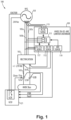
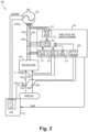
- a high voltage DC (HVDC) system 100 can include a generator 101 configured to output alternating current (AC).
- the system 100 can include a rectifier 103 connected to the generator 101 via AC phase lines 105a, 105b, 105c (e.g., 3 phase or 6 phase).
- the rectifier 103 can be configured to convert the AC to DC to output the DC to DC feeder lines 107a, 107b.
- the system 100 can include a crowbar system 109.
- the crowbar system 109 can include a switch module 111 operatively connected to the AC phase lines 105a, 105b, 105c (or additional phase sets) to prevent AC from flowing to the rectifier 103 in a cutoff state.
- the crowbar system 109 can be configured to determine whether at least one cutoff condition exists.
- the at least one cutoff condition can be or include one or more of (e.g., any combination of, all of) an AC overcurrent from the generator 101, a DC overcurrent downstream of the rectifier 103, a DC overvoltage downstream of the rectifier, an arc fault (e.g., anywhere in the system 100). Any other suitable condition, (e.g., AC overvoltage) is also contemplated herein has a cutoff condition.
- the crowbar system 109 can be configured to control the switch module 111 to the cutoff state if the at least one cutoff condition exists.
- the crowbar system 109 can include a DC overcurrent sense module 113 operatively connected to the rectifier 103 and/or the DC feeder lines 107a, 107b to sense a DC side current on the DC feeder lines 107a, b.
- the DC side overcurrent sense module 113 can be configured to control the switch module 111 to activate the switch module 111 to short each AC line 105a, b, c together in the cutoff state when the DC side current is above a DC side overcurrent threshold.
- the crowbar system 109 can include a DC overvoltage sense module 220 operatively connected to the system DC Point of Regulation (POR) and/or the DC lines 107a, 107b to sense a DC side voltage on the DC feeder lines 107a, b.
- the DC side overvoltage sense module 220 can be configured to control the switch module 111 to activate the switch module 111 to short each AC line 105a, b, c together in the cutoff state when the DC side voltage is above a DC side overvoltage threshold.
- the crowbar system 109 can include an AC side overcurrent sense module 115 operatively connected to the generator 101 and/or the AC phase lines 105a, b, c (e.g., via the same number of respective sense lines, e.g., as shown) to sense an AC side current on the AC phase lines 105a, b, c (e.g., individually or as a group).
- the AC side overcurrent sense module 115 can be configured to control the switch module 111 to activate the switch module 111 to short each AC line 105a, b, c together in the cutoff state when an AC side current is above an AC side overcurrent threshold.
- the crowbar system 109 can include an AC side overvoltage sense module 117 operatively connected to the AC phase lines 105a, b, c (e.g., via the same number of respective sense lines, e.g., as shown) to sense an AC side voltage on the AC phase lines 105a, b, c (e.g., individually or as a group).
- the AC side overvoltage sense module 117 can be configured to control the switch module 111 to activate the switch module 111 to short each AC line together 105a, b, c in the cutoff state when the AC side voltage is above an AC side overvoltage threshold.
- the AC side overvoltage sense module 117 can be connected to the AC phase lines 105a, b, c between the switch module 111 and the rectifier 103.
- the AC overcurrent sense module 115 is connected to the AC phase lines 105a, b, c between the generator 101 and the switch module 111. Any other suitable connection is contemplated herein.
- the crowbar system 109 can include an arc sense module 119 configured to sense an arc fault in the system 100 (e.g., at utilization equipment or damaged wire).
- the arc sense module 119 can be configured to control the switch module 111 to activate the switch module 111 to short each AC line 105a, b, c together in the cutoff state when an arc fault is detected.
- the arc sense module 119 can include arc sense logic (e.g., using current sensing, voltage sensing, visual sensors, etc.) at any suitable location (e.g., the DC side of the rectifier 103).
- the system 100 can include a generator control unit (GCU) 121 operatively connected to the crowbar system 109 to receive one or more signals from the crowbar system 109.
- the GCU 121 can be operatively connected to the generator 101 to control generator output.
- the crowbar system 109 can be configured to send a fault signal to the GCU 121 in the cutoff state to cause the GCU 121 to reduce generator voltage output and/or to shut down the generator 101 to cease generator voltage output.
- the generator 101 is a variable frequency generator (VFG), and the GCU 121 can be configured to control excitation energy input to the generator 101 to control the generator output.
- the system 100 can include one or more contactors 123a, 123b on each DC line between the rectifier 103 and a DC bus 125.
- the GCU 121 can be configured to control the contactors 123a, b to allow or prevent DC voltage to the DC bus 125.
- Any suitable module(s) of this disclosure can include any suitable hardware and/or software module(s) configured to perform the disclosed function.
- modules e.g., modules 111, 113, 115, 117, 119, 220
- can be configured to react quickly enough e.g., such as sub 50ms response time
- embodiments can include one or more analog circuit modules configured to react quickly enough, or the modules can include suitable fast reacting firmware.
- a method can include sensing whether an overcurrent exists in a high voltage generator system, and shorting multiple phases together in response to an overcurrent in order to cancel current output to protect downstream equipment.
- the method can include any other suitable method(s) and/or portion(s) thereof.
- Embodiments can include a crowbar system (e.g., a solid state limiter) that reacts quick to overcurrent in one or more locations.
- Embodiments can include a high voltage DC (HVDC) system overvoltage, overcurrent, and arc fault (OV-OC-Arc) limiter crowbar system.
- HVDC high voltage DC
- OV-OC-Arc arc fault limiter crowbar system.
- Embodiments can utilize the crowbar method for dissipating HVDC generator/rectifier system high voltage, current and/or arc fault conditions.
- generator current and/or rectifier current output current can be monitored by the HVDC current/arc limiter crowbar, and if defined abnormal levels for a given system are detected, the HVDC OV-OC-Arc Limiter Crowbar can trigger to short the generator power feeds and additionally coordinate GCU de-excitation of the channel.
- Reset can be automated with dedicated customer preference rules (e.g., such as once per flight cycle), or manually via a flight deck switch.
- Voltage levels illustrated are for a 230 Vac VFG and +/- 270 Vdc rectifier example, but the embodiments can be scaled for other architecture power levels such as 270 Vdc to ground systems and +/- 540V for electric propulsion. Any suitable voltage system for application of embodiments is contemplated herein.
- Embodiments provide a method for managing HVDC fault voltage/current/arc conditions, for example.
- Embodiments can provide benefits that include fast overvoltage, overcurrent, and arc fault response for HVDC to limit structure, panel, equipment damage, independent functionality to support any potential safety requirements, and extended contactor life thru reduce energy isolation coordination. Any other suitable benefits are contemplated herein.
- aspects of the present disclosure may be embodied as a system, method or computer program product. Accordingly, aspects of this disclosure may take the form of an entirely hardware embodiment, an entirely software embodiment (including firmware, resident software, micro-code, etc.), or an embodiment combining software and hardware aspects, all possibilities of which can be referred to herein as a "circuit,” “module,” or “system.”
- a “circuit,” “module,” or “system” can include one or more portions of one or more separate physical hardware and/or software components that can together perform the disclosed function of the "circuit,” “module,” or “system”, or a “circuit,” “module,” or “system” can be a single self-contained unit (e.g., of hardware and/or software).
- aspects of this disclosure may take the form of a computer program product embodied in one or more computer readable medium(s) having computer readable program code embodied thereon.
- a computer readable storage medium may be any tangible medium that can contain, or store a program for use by or in connection with an instruction execution system, apparatus, or device.
- Computer program code for carrying out operations for aspects of this disclosure may be written in any combination of one or more programming languages, including an object oriented programming language such as Java, Smalltalk, C++ or the like and conventional procedural programming languages, such as the "C" programming language or similar programming languages.
- the program code may execute entirely on the user's computer, partly on the user's computer, as a stand-alone software package, partly on the user's computer and partly on a remote computer or entirely on the remote computer or server.
- the remote computer may be connected to the user's computer through any type of network, including a local area network (LAN) or a wide area network (WAN), or the connection may be made to an external computer (for example, through the Internet using an Internet Service Provider).
- LAN local area network
- WAN wide area network
- Internet Service Provider for example, AT&T, MCI, Sprint, EarthLink, MSN, GTE, etc.
- a reference to "A and/or B", when used in conjunction with open-ended language such as “comprising” can refer, in one embodiment, to A only (optionally including elements other than B); in another embodiment, to B only (optionally including elements other than A); in yet another embodiment, to both A and B (optionally including other elements); etc.
Landscapes
- Engineering & Computer Science (AREA)
- Power Engineering (AREA)
- Aviation & Aerospace Engineering (AREA)
- Emergency Protection Circuit Devices (AREA)
Applications Claiming Priority (1)
| Application Number | Priority Date | Filing Date | Title |
|---|---|---|---|
| US17/521,411 US20230144976A1 (en) | 2021-11-08 | 2021-11-08 | High voltage dc systems |
Publications (1)
| Publication Number | Publication Date |
|---|---|
| EP4178055A1 true EP4178055A1 (de) | 2023-05-10 |
Family
ID=84329828
Family Applications (1)
| Application Number | Title | Priority Date | Filing Date |
|---|---|---|---|
| EP22205870.3A Pending EP4178055A1 (de) | 2021-11-08 | 2022-11-07 | Hochspannungsgleichstromsysteme |
Country Status (2)
| Country | Link |
|---|---|
| US (1) | US20230144976A1 (de) |
| EP (1) | EP4178055A1 (de) |
Families Citing this family (4)
| Publication number | Priority date | Publication date | Assignee | Title |
|---|---|---|---|---|
| US12081014B2 (en) | 2020-12-23 | 2024-09-03 | Hamilton Sundstrand Corporation | Fault clearing in midpoint grounded systems |
| EP4376240A1 (de) * | 2022-11-23 | 2024-05-29 | Abb Schweiz Ag | Antriebssystem mit schutzmöglichkeit |
| CN118659429B (zh) * | 2024-05-27 | 2025-10-24 | 中国电力科学研究院有限公司 | 一种控制故障后直流送端工频暂时过电压的方法和装置 |
| WO2026067952A1 (en) | 2024-09-30 | 2026-04-02 | Vestas Wind Systems A/S | Arc quenching in wind turbines |
Citations (4)
| Publication number | Priority date | Publication date | Assignee | Title |
|---|---|---|---|---|
| DE1119985B (de) * | 1959-10-09 | 1961-12-21 | Siemens Ag | UEberstromschutz fuer Gleichrichteranlagen |
| US9407083B1 (en) * | 2012-04-26 | 2016-08-02 | The Boeing Company | Combined subtransient current suppression and overvoltage transient protection |
| WO2016146086A2 (en) * | 2015-03-19 | 2016-09-22 | Ripd Research And Ip Development Ltd. | Devices for overvoltage, overcurrent and arc flash protection |
| WO2017027563A1 (en) * | 2015-08-13 | 2017-02-16 | Abb Schweiz Ag | Dc output wind turbine with power dissipation |
Family Cites Families (3)
| Publication number | Priority date | Publication date | Assignee | Title |
|---|---|---|---|---|
| US8492979B2 (en) * | 2010-03-25 | 2013-07-23 | General Electric Company | Plasma generation apparatus |
| EP3414819B1 (de) * | 2016-02-12 | 2020-01-08 | ABB Schweiz AG | Konverter-modul für ein hgü-kraftwerk |
| US11456677B2 (en) * | 2020-12-10 | 2022-09-27 | Rolls-Royce Corporation | Power converter protection circuit |
-
2021
- 2021-11-08 US US17/521,411 patent/US20230144976A1/en not_active Abandoned
-
2022
- 2022-11-07 EP EP22205870.3A patent/EP4178055A1/de active Pending
Patent Citations (4)
| Publication number | Priority date | Publication date | Assignee | Title |
|---|---|---|---|---|
| DE1119985B (de) * | 1959-10-09 | 1961-12-21 | Siemens Ag | UEberstromschutz fuer Gleichrichteranlagen |
| US9407083B1 (en) * | 2012-04-26 | 2016-08-02 | The Boeing Company | Combined subtransient current suppression and overvoltage transient protection |
| WO2016146086A2 (en) * | 2015-03-19 | 2016-09-22 | Ripd Research And Ip Development Ltd. | Devices for overvoltage, overcurrent and arc flash protection |
| WO2017027563A1 (en) * | 2015-08-13 | 2017-02-16 | Abb Schweiz Ag | Dc output wind turbine with power dissipation |
Also Published As
| Publication number | Publication date |
|---|---|
| US20230144976A1 (en) | 2023-05-11 |
Similar Documents
| Publication | Publication Date | Title |
|---|---|---|
| EP4178055A1 (de) | Hochspannungsgleichstromsysteme | |
| EP2602893B1 (de) | Energieversorgungssystemschutz | |
| JP6234647B1 (ja) | 直流電気回路保護装置およびアーク検出方法 | |
| US20140361621A1 (en) | DC-Power System With System Protection Capabilities | |
| EP3258563B1 (de) | Schutzvorrichtung und schutzsystem | |
| US9071051B2 (en) | Overvoltage protection unit with AC input current sensors | |
| WO2017221493A1 (ja) | 直流電気回路保護装置およびアーク検出方法 | |
| US10476258B2 (en) | Method of operating a protection device, associated computer program product, protection device and electrical installation | |
| US9722408B2 (en) | ARC-free capacitor trip device | |
| US8699188B2 (en) | Shunt regulator for overvoltage protection at transformer rectifier unit of electrical generating system | |
| CN105099134B (zh) | 电力电子变换系统中直流母线电容电压的泄放方法及装置 | |
| CN108134372A (zh) | 电抗器电流互感器断线识别方法、差动保护方法及装置 | |
| US11349299B2 (en) | Transformer rectifier unit power quality protection | |
| US20220166210A1 (en) | Solid state circuit breaker, method for operating same, and control apparatus of solid state circuit breaker | |
| CN105098717B (zh) | 接触器保护方法及装置 | |
| Bapat et al. | Advanced concepts in high resistance grounding | |
| EP2503658A1 (de) | Kurzschlussschutz für Systeme mit elektrischen Maschinen | |
| Panetta | Hybrid grounding of electrical systems | |
| EP3667850A1 (de) | Elektrisches system für fahrzeuge mit überspannungsschutz | |
| EP3780373A1 (de) | Stromumwandlungsvorrichtung | |
| CN113678336B (zh) | 控制固态断路器的方法、装置和固态断路器 | |
| US11641101B2 (en) | Arc fault induced differential protection isolation | |
| EP4523952A1 (de) | Systeme für versorgungsausrüstungen für elektrische gruppenfahrzeuge | |
| WO2020121466A1 (ja) | 電力供給システムおよび電力供給方法 | |
| JP4836663B2 (ja) | ループ系統保護装置と方法 |
Legal Events
| Date | Code | Title | Description |
|---|---|---|---|
| PUAI | Public reference made under article 153(3) epc to a published international application that has entered the european phase |
Free format text: ORIGINAL CODE: 0009012 |
|
| STAA | Information on the status of an ep patent application or granted ep patent |
Free format text: STATUS: THE APPLICATION HAS BEEN PUBLISHED |
|
| AK | Designated contracting states |
Kind code of ref document: A1 Designated state(s): AL AT BE BG CH CY CZ DE DK EE ES FI FR GB GR HR HU IE IS IT LI LT LU LV MC ME MK MT NL NO PL PT RO RS SE SI SK SM TR |
|
| STAA | Information on the status of an ep patent application or granted ep patent |
Free format text: STATUS: REQUEST FOR EXAMINATION WAS MADE |
|
| 17P | Request for examination filed |
Effective date: 20231110 |
|
| RBV | Designated contracting states (corrected) |
Designated state(s): AL AT BE BG CH CY CZ DE DK EE ES FI FR GB GR HR HU IE IS IT LI LT LU LV MC ME MK MT NL NO PL PT RO RS SE SI SK SM TR |