EP4178073A1 - System und verfahren zur überwachung und steuerung eines stromversorgungssystems - Google Patents
System und verfahren zur überwachung und steuerung eines stromversorgungssystems Download PDFInfo
- Publication number
- EP4178073A1 EP4178073A1 EP21834669.0A EP21834669A EP4178073A1 EP 4178073 A1 EP4178073 A1 EP 4178073A1 EP 21834669 A EP21834669 A EP 21834669A EP 4178073 A1 EP4178073 A1 EP 4178073A1
- Authority
- EP
- European Patent Office
- Prior art keywords
- contingency
- power
- power system
- data
- disaster
- Prior art date
- Legal status (The legal status is an assumption and is not a legal conclusion. Google has not performed a legal analysis and makes no representation as to the accuracy of the status listed.)
- Pending
Links
Images








Classifications
-
- G—PHYSICS
- G05—CONTROLLING; REGULATING
- G05B—CONTROL OR REGULATING SYSTEMS IN GENERAL; FUNCTIONAL ELEMENTS OF SUCH SYSTEMS; MONITORING OR TESTING ARRANGEMENTS FOR SUCH SYSTEMS OR ELEMENTS
- G05B23/00—Testing or monitoring of control systems or parts thereof
- G05B23/02—Electric testing or monitoring
- G05B23/0205—Electric testing or monitoring by means of a monitoring system capable of detecting and responding to faults
- G05B23/0259—Electric testing or monitoring by means of a monitoring system capable of detecting and responding to faults characterized by the response to fault detection
- G05B23/0286—Modifications to the monitored process, e.g. stopping operation or adapting control
- G05B23/0291—Switching into safety or degraded mode, e.g. protection and supervision after failure
-
- G—PHYSICS
- G06—COMPUTING OR CALCULATING; COUNTING
- G06Q—INFORMATION AND COMMUNICATION TECHNOLOGY [ICT] SPECIALLY ADAPTED FOR ADMINISTRATIVE, COMMERCIAL, FINANCIAL, MANAGERIAL OR SUPERVISORY PURPOSES; SYSTEMS OR METHODS SPECIALLY ADAPTED FOR ADMINISTRATIVE, COMMERCIAL, FINANCIAL, MANAGERIAL OR SUPERVISORY PURPOSES, NOT OTHERWISE PROVIDED FOR
- G06Q50/00—Information and communication technology [ICT] specially adapted for implementation of business processes of specific business sectors, e.g. utilities or tourism
- G06Q50/06—Energy or water supply
-
- G—PHYSICS
- G06—COMPUTING OR CALCULATING; COUNTING
- G06Q—INFORMATION AND COMMUNICATION TECHNOLOGY [ICT] SPECIALLY ADAPTED FOR ADMINISTRATIVE, COMMERCIAL, FINANCIAL, MANAGERIAL OR SUPERVISORY PURPOSES; SYSTEMS OR METHODS SPECIALLY ADAPTED FOR ADMINISTRATIVE, COMMERCIAL, FINANCIAL, MANAGERIAL OR SUPERVISORY PURPOSES, NOT OTHERWISE PROVIDED FOR
- G06Q10/00—Administration; Management
- G06Q10/06—Resources, workflows, human or project management; Enterprise or organisation planning; Enterprise or organisation modelling
- G06Q10/063—Operations research, analysis or management
- G06Q10/0635—Risk analysis of enterprise or organisation activities
-
- G—PHYSICS
- G06—COMPUTING OR CALCULATING; COUNTING
- G06Q—INFORMATION AND COMMUNICATION TECHNOLOGY [ICT] SPECIALLY ADAPTED FOR ADMINISTRATIVE, COMMERCIAL, FINANCIAL, MANAGERIAL OR SUPERVISORY PURPOSES; SYSTEMS OR METHODS SPECIALLY ADAPTED FOR ADMINISTRATIVE, COMMERCIAL, FINANCIAL, MANAGERIAL OR SUPERVISORY PURPOSES, NOT OTHERWISE PROVIDED FOR
- G06Q10/00—Administration; Management
- G06Q10/20—Administration of product repair or maintenance
-
- H—ELECTRICITY
- H02—GENERATION; CONVERSION OR DISTRIBUTION OF ELECTRIC POWER
- H02J—ELECTRIC POWER NETWORKS; CIRCUIT ARRANGEMENTS OR SYSTEMS FOR SUPPLYING OR DISTRIBUTING ELECTRIC POWER; SYSTEMS FOR STORING ELECTRIC ENERGY
- H02J13/00—Circuit arrangements for providing remote monitoring or remote control of equipment in a power distribution network
- H02J13/10—Circuit arrangements for providing remote monitoring or remote control of equipment in a power distribution network characterised by displaying of information or by user interaction, e.g. supervisory control and data acquisition [SCADA] systems
-
- H—ELECTRICITY
- H02—GENERATION; CONVERSION OR DISTRIBUTION OF ELECTRIC POWER
- H02J—ELECTRIC POWER NETWORKS; CIRCUIT ARRANGEMENTS OR SYSTEMS FOR SUPPLYING OR DISTRIBUTING ELECTRIC POWER; SYSTEMS FOR STORING ELECTRIC ENERGY
- H02J13/00—Circuit arrangements for providing remote monitoring or remote control of equipment in a power distribution network
- H02J13/12—Monitoring network conditions, e.g. electrical magnitudes or operational status
-
- H—ELECTRICITY
- H02—GENERATION; CONVERSION OR DISTRIBUTION OF ELECTRIC POWER
- H02J—ELECTRIC POWER NETWORKS; CIRCUIT ARRANGEMENTS OR SYSTEMS FOR SUPPLYING OR DISTRIBUTING ELECTRIC POWER; SYSTEMS FOR STORING ELECTRIC ENERGY
- H02J3/00—Circuit arrangements for AC mains or AC distribution networks
- H02J3/001—Arrangements for handling faults or abnormalities, e.g. emergencies or contingencies
- H02J3/0012—Arrangements for handling faults or abnormalities, e.g. emergencies or contingencies characterised by the contingency detection means in AC networks, e.g. using phasor measurement units [PMU], synchrophasors or contingency analysis
-
- G—PHYSICS
- G05—CONTROLLING; REGULATING
- G05B—CONTROL OR REGULATING SYSTEMS IN GENERAL; FUNCTIONAL ELEMENTS OF SUCH SYSTEMS; MONITORING OR TESTING ARRANGEMENTS FOR SUCH SYSTEMS OR ELEMENTS
- G05B2223/00—Indexing scheme associated with group G05B23/00
- G05B2223/06—Remote monitoring
Definitions
- the present invention relates to a power system monitoring control system and method and is particularly suitable for application to a power system monitoring control system including a system stabilization system.
- the generated power is supplied to consumers via transmission lines, but the upper limit of the amount of power that can flow through each transmission line is determined by the operation standard of the transmission line.
- the operator of the power system calculates a thermal capacity for each transmission line, a power capacity of which stability (transient stability, voltage stability, frequency, and the like) during the occurrence of the failure can be maintained, or the like based on the results of preliminary simulations and desk studies and sets the lowest value (that is, the strictest value) among the values as the operation standard for the transmission line.
- the “system stabilization system” refers to a power system that, has a function of preventing, in advance, proceeding into a situation that the influence is likely to spread and cause a large-scale blackout in the case of occurrence of a failure in the power system due to an earthquake, lightning strike, tsunami, or the like.
- the system stabilization system retains a control table in which each of the generators (power-supply-constrained target) to be constrained in power supply and the target (load-constrained target) to be load-constrained target is registered in advance so as to maintain the stability of the power system. Then, when the failure actually occurs in the power system, the system stabilization system determines the power-supply-constrained target or load-constrained target according to the failure content with reference to the control table and maintains the stability of the power system by disconnecting the determined power-supply-constrained target or load-constrained target from the power system. Since the stability can be maintained at the time of a failure by the function of the system stabilization system, the amount of power flowing through the transmission line can be increased, and the operation standard can be relaxed.
- JP-A-2019-71710 discloses "system constraints which are technical constraints in various sites of the power system and plan information which is a plan for power procurement are acquired from a market management system, post-change system constraints which are results of reviewing the system constraints are generated, and the generated post-change system constraints are output to the market management system". It is noted that, the "system constraint" in this PTL 1 corresponds to the "operation standard" in this application.
- the system stabilization system is a protection power system
- the accountability for the creation and updating of the control table is required to be fulfilled.
- the accountability can be fulfilled by disclosing the conditions and results of preliminary simulations and desk studies, but when the contingency assumed at the time of generating the control table is allowed to be dynamically changed according to a situation, the transparency of change conditions and results is required to be ensured.
- the present invention is to propose a power system monitoring control system and method that can improve supply reliability and resiliency of a power system while fulfilling the accountability.
- a power system monitoring control system that retains a control table in which a control target to be controlled to maintain stability of a power system when a failure occurs for each type of the failure is registered and, when the failure occurs in the power system, controls the control target according to the type of the failure according to the control table
- the power system monitoring control system including: an contingency point estimation unit that estimates an contingency point which is an occurrence point of the failure assumed in the power system based on predetermined disaster information; an assumed disaster content estimation unit that estimates, for each contingency point, an assumed disaster content which is a content of a disaster assumed to occur at the contingency point based on the disaster information and an estimation result of the contingency point estimation unit; a contingency changing unit that changes the contingency data based on an estimation result of the assumed disaster content estimation unit, contingency data including an occurrence site and an aspect of each of the failures assumed to occuur in the power system, and an contingency change rule including
- a power system monitoring control method executed by a power system monitoring control system that retains a control table in which a control target to be controlled to maintain stability of a power system when a failure occurs for each type of the failure is registered and, when the failure occurs in the power system, controls the control target according to the type of the failure according to the control table
- the power system monitoring control method including: estimating an contingency point which is an occurrence point of the failure assumed in the power system based on predetermined disaster information; estimating, for each contingency point, an assumed disaster content which is a content of the disaster that is assumed to occur at the contingency point based on the disaster information and an estimation result of the contingency point; changing the contingency data based on an estimation result of the assumed disaster content at each contingency point, contingency data including an occurrence site and an aspect of each of the failures assumed to occur in the power system, and an contingency change rule including an contingency data change rule; and updating the control table based on changed cont
- the accountability for the control table can be sufficiently fulfilled.
- numerical reference 1 generally indicates a power system monitoring control system according to the present embodiment.
- the power system monitoring control system 1 is configured to include a system stabilization system 3 and a power system monitoring control apparatus 4 which are connected via a network 2.
- the system stabilization system 3 is a computer device having functions of retaining a control table 76 ( Fig. 9A ) in which a power-supply-constrained target or a load-constrained target for each failure (hereinafter, referred to as a contingency) that is assumed to occur in a target power system (hereinafter, referred to as a target power system) is registered and disconnecting the required power-supply-constrained target or the required load-constrained target from the target power system or performing output control based on the control table 76 when a contingency occurs in the target power system.
- a control table 76 Fig. 9A
- a contingency a power-supply-constrained target or a load-constrained target for each failure
- the system stabilization system 3 is configured to include information processing resources such as a CPU (Central Processing Unit) 10, a memory 11, and a storage device 12.
- the CPU 10 is a processor that controls operations of the system stabilization system 3 as a whole.
- the memory 11 is configured with a RAM (Random Access Memory) or the like, and is used as a work memory for the CPU 10.
- the storage device 12 is configured with a non-volatile storage device such as a hard disk device or an SSD (Solid State Drive) and is used to store data and programs to be retained for a long period of time.
- the power system monitoring control apparatus 4 is a computer device having a function of updating the control table 76 retained by the system stabilization system 3 and is configured to include a CPU 20, a memory 21, a storage device 22, a communication device 23, an input device 24, and a display device 25.
- the communication device 23 is a communication device that performs protocol control during communication with the system stabilization system 3 via the network 2 and is configured with an NIC (Network Interface Card) or the like.
- the input device 24 is used by an operator (hereafter, simply referred to as an operator) of the power system monitoring control apparatus 4 to input required information and instruction to the power system monitoring control apparatus 4 and is configured with, for example, a pointing device such as a keyboard and a mouse, a touch panel, a voice instruction device, and/or the like.
- the display device 25 is used to display a necessary screen and information and is configured with a display device such as a liquid crystal display or an organic EL (Electro Luminescence) display.
- a printer device or an audio output device may be applied instead of or in addition to the display device.
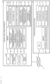
- Fig. 2 illustrates a logical configuration of the power system monitoring control apparatus 4 and the system stabilization system 3 according to the present embodiment.
- the power system monitoring control apparatus 4 is configured to include a contingency change input database group 30, a contingency changing unit 31, and a contingency change result database group 32.
- the contingency change input database group 30 is configured with a disaster information database 40, an contingency database 42, and an contingency change rule database 44.
- the disaster information database 40 is a database that stores disaster information 41 created in advance, for example, for each 30-minute time zone (hereinafter, simply referred to as a time zone).
- the "disaster information" in the present embodiment is information of a combination of an occurrence point ("disaster point") and a content ("disaster content”) of a disaster that is likely to occur in the target power system in the corresponding time zone or that has occurred in the past.
- the disaster information 41 for each time zone is registered. For example, in the case of the example in Fig.
- the disaster information 41 at "0:00" in “YYYY/MM/DD” represents a content that a disaster due to "typhoon” occurs in an "area A”, “landslide” occurs in an “area B”, and “tsunami” occurs in an "area C” in the time zone starting from the date and time ("0:00" in "YYYY/MM/DD").
- the "disaster point" in the disaster information 41 is not limited to the "area”, but the “disaster point” may be a power line, a substation, or the like within the area or may be other point information.
- the "disaster content” in the disaster information database 40 is not limited to large-scale disasters such as typhoons, earthquakes, landslides, and tsunamis, but the “disaster content” may also be a content about a weather condition such as heavy snow, heavy rain, strong winds, or drought. The same applies to the following.
- the "time zone" in the disaster information 41 may be either past or future date and time.
- the "disaster point” and “disaster content” of the disaster information 41 become actual results, and when the time zone is a future date and time, the "disaster Point” and “disaster content” become predictions.
- the disaster information 41 of the past time zone may be disaster information of a virtual disaster that is not an actual result. By doing so, the contingencies described later can be changed according to various disasters in each time zone.
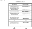
- the contingency database 42 is a database in which data (hereinafter, referred to as contingency data) 43 related to a plurality of fixed contingencies created in advance for the target power system is registered. As illustrated in Fig. 4 , the contingency data 43 has a table configuration with a failure site column 43A and a failure aspect column 43B. In the contingency data 43, one row corresponds to one contingency related to the target power system.
- the failure site column 43A stores the occurrence location of the corresponding contingency
- the failure aspect column 43B stores the aspect (the failure aspect) of the contingency.
- the "failure aspect” is a combination of a phase, the number of lines, the failure aspect, and the like of a failure line, and for example, in Fig. 4 , "3 ⁇ 6LG (ABCA'B'C')" denotes a 3-phase 6-line ground failure and denotes that there are ground failures between an A phase, a B phase, and a C phase and an A' phase, a B' phase, and a C' phase.
- the contingency change rule database 44 is a database in which data (hereinafter, referred to as an contingency change rule data) 45 of a rule (hereinafter, referred to as an contingency change rule) for changing a contengency registered in the contingency database 42 is stored and is created in advance by the operator.
- the contingency change rule data 45 has a table configuration including a disaster point column 45A, a disaster content column 45B, and a contingency change content column 45C. In the contingency change rule data 45, one row corresponds to one contingency change rule.
- the disaster point column 45A stores all points ("disaster points") where disaster is assumed to occur
- the disaster content column 45B stores contents ("disaster contents") of all the disasters which are assumed to occur at the corresponding disaster points.
- the contingency change content column 45C stores a change content (hereinafter, referred to as a contingency change content) of a contingency which is assumed to occur when the corresponding disaster content occurs at the corresponding disaster point. Since the contingency change contents differ according to the combination of the disaster point and the disaster content, each contingency change content is a content according to the combination of the disaster point and the disaster content.
- Fig. 5 for example in “area A”, it is illustrated that disasters such as “typhoon”, “landslide”, and “tsunami” are assumed to occur, and when the "typhoon” approaches, the “4-line ground failure in the area A (4-line ground failure in the area A)" is to be added to the original contingency, and when the "landslide” occurs, the “dropout on the power supply 1 site in the area A (dropout on the power supply 1 site in the area A)” is to be added to the original contingency. It is noted that Fig. 5 also illustrates that there is no contingency even when "tsunami" occurs in the "area A".
- the contingencies can be changed according to various disasters at various points.
- the content of change in the contingency with respect to the disaster point and disaster content is clarified, transparency is ensured when the contingency is changed, and the accountability to third parties can be fulfilled.
- the contingency changing unit 31 is configured to include an contingency point estimation unit 50, an assumed disaster content estimation unit 51, a contingency changing unit 52, a post-change contingency transmission unit 53, and a display unit 54.
- the contingency point estimation unit 50 is a functional unit that is realized by the CPU 20 ( Fig. 1 ) of the power system monitoring control apparatus 4 executing an contingency point estimation program 50P ( Fig. 1 ) stored in the memory 21 ( Fig. 1 ).
- the contingency point estimation unit 50 has a function of estimating each of all the points (hereinafter, referred to as contingency points) in the target power system where a contingency may occur due to some disaster for each time zone based on each disaster information 41 registered in the disaster information database 40.
- the contingency point estimation unit 50 registers the data representing each estimated contingency point for each time zone as contingency point estimation result data 61 in an contingency point estimation result database 60 of the contingency change result database group 32 described later and outputs the contingency point estimation result data 61 to the assumed disaster content estimation unit 51.
- the assumed disaster content estimation unit 51 is a functional unit that is realized by the CPU 20 of the power system monitoring control apparatus 4 executing an assumed disaster content estimation program 51P ( Fig. 1 ) stored in the memory 21.
- the assumed disaster content estimation unit 51 has a function of estimating the content (hereinafter, referred to as an assumed disaster content) of the disaster that is assumed to occur at each contingency point for each time zone based on the contingency point estimation result data 61 for each time zone provided from the contingency point estimation unit 50 and each disaster information 41 registered in the disaster information database 40.
- the assumed disaster content estimation unit 51 registers the data representing a combination of each contingency point for each time zone and the assumed disaster content estimated for the contingency point as assumed disaster content estimation result data 63 in an assumed disaster content estimation result database 62 of the contingency change result database group 32 described later and outputs the assumed disaster content estimation result data 63 to the contingency changing unit 52.
- the contingency changing unit 52 is a functional unit that is realized by the CPU 20 of the power system monitoring control apparatus 4 executing a contingency changing program 52P ( Fig. 1 ) stored in the memory 21.
- the contingency changing unit 52 has a function of calculating all contingencies for each time zone based on the assumed disaster content estimation result data 63 for each time zone provided from the assumed disaster content estimation unit 51, the contingency data 43 stored in the contingency database 42, and the contingency change rule data 45 stored in the contingency change rule database 44.
- the contingency changing unit 52 registers the calculated contingency data for each time zone as contingency change result data 65 in a contingency change result database 64 of the contingency change result database group 32 described later and outputs the contingency change result data 65 to the transmission unit 53.
- the post-change contingency transmission unit 53 is a functional unit that is realized by the CPU 20 of the power system monitoring control apparatus 4 executing a post-change contingency transmission program 53P stored in the memory 21.
- the post-change contingency transmission unit 53 transmits the contingency change result data 65 for each time zone provided from the contingency changing unit 52 to the system stabilization system 3 via the communication device 23 ( Fig. 1 ).
- the display unit 54 is a functional unit that is realized by the CPU 20 of the power system monitoring control apparatus 4 executing a display program 54P stored in the memory 21.
- the display unit 54 generates an contingency change result display screen 80, which will be described later with reference to Fig. 10 based on the contingency point estimation result data 61 for each time zone stored in the contingency point estimation result database 60, the assumed disaster content estimation result data 63 for each time zone registered in the assumed disaster content estimation result database 62, and the contingency change result data 65 for each time zone stored in the contingency change result database 64.
- the display unit 54 outputs screen data of the generated contingency change result display screen 80 to the display device 25 ( Fig. 1 ) to display the contingency change result display screen 80 on the display device 25.
- the contingency change result database group 32 is configured with the contingency point estimation result database 60, the assumed disaster content estimation result database 62, and the contingency change result database 64.
- the contingency point estimation result database 60 is a database used for managing the contingency point estimated by the contingency point estimation unit 50 of the contingency changing unit 31 as described above. As illustrated in Fig. 6 , the contingency point estimation result database 60 stores the contingency point estimation result data 61 for each time zone. Each contingency point estimation result data 61 includes data representing all contingency time points in the corresponding time zone. Therefore, in the case of the example of Fig. 6 , the occurrence points (contingency points) of some failure assumed at "0:00" of "YYYY/MM/DD" estimated by the contingency point estimation unit 50 are indicated by three sites of the "area A", the "area B" and the "area C".
- the assumed disaster content estimation result database 62 is a database used for managing the contingency content for each contingency point for each time zone estimated by the assumed disaster content estimation unit 51. As illustrated in Fig. 7 , the assumed disaster content estimation result database 62 stores the assumed disaster content for each contingency point for each time zone. Therefore, in the case of the example of Fig. 7 , it is illustrated that the assumed disaster content of the "area A" which is the contingency point of "0:00" of "YYYY/MM/DD" estimated by the assumed disaster content estimation unit 51 is "typhoon", the assumed disaster content of the "area B” is "landslide”, and the assumed disaster content of the "area C” is "tsunami".
- the contingency change result database 64 is a database used for managing the contingency change results changed by the contingency changing unit 52. As illustrated in Fig. 8 , the contingency change result database 64 stores the contingency change result data 65 that is configured with the updated contingency data 43 ( Fig. 4 ) for each time zone. Therefore, in the case of the example of Fig. 8 , with respect to each contingency illustrated in Fig.
- the contingency point estimation result database 60, the assumed disaster content estimation result database 62, and the contingency change result database 64 include and store the result data at the time of an intermediate process so as to be used in an appropriate situation in addition to the contingency point estimation result data 61, the assumed disaster content estimation result data 63, or the contingency change result data 65 as respective calculation results.
- system stabilization system 3 is configured to include an contingency database 70, a system data database 72, a control table generation unit 74, and a control table database 75, as illustrated in Fig. 2 .
- the contingency database 70 of the system stabilization system 3 is a database having the same configuration as the contingency database 42 ( Fig. 4 ) of the power system monitoring control apparatus 4.
- the contingency database 70 stores the same contingency data 71 as the contingency data 43 stored in the contingency database 42, and when the contingency data 43 is updated, the contingency data 71 is also similarly updated in synchronization with the updating.
- the system data database 72 is a database used for managing system data 73 required for power flow calculation, state estimation, and time series change calculation of the power system.
- the system data database 72 includes data such as system configuration of the power system, line impedance (R + jX), ground capacitance (susceptance: jB), system configuration and threshold value of pad data required for state estimation, generator data, and other required data are stored in advance as the system data 73.
- the control table generation unit 74 is a functional unit that is realized by the CPU 10 ( Fig. 1 ) of the system stabilization system 3 executing a control table generation program 74P ( Fig. 1 ) stored in the memory 11 ( Fig. 1 ).
- the control table generation unit 74 generates the control table 76 based on the contingency data 71 stored in the contingency database 70 and the system data 73 stored in the system data database 72 and stores the generated control table 76 in the table database 75.
- the control table generation unit 74 when the contingency change result data 65 which is the contingency data 43 updated by the contingency changing unit 52 of the power system monitoring control apparatus 4 is transmitted, the control table generation unit 74 generates the new control table 76 for each time zone based on the contingency change result data 65, the contingency data 71 stored in the contingency database 70, and the system data 73 stored in the system data database 72. It is noted that the control table 76 created at this time is a relaxed control table on the premise of using the system stabilization system 3.
- control table generation unit 74 overwrites the data of the control table 76 stored in the control table database 75 with the data of the new control table 76 generated for each time zone. Therefore, the control table 76 stored in the control table database 75 is updated to the new control table 76.
- the control table database 75 is a database used for managing the control table 76 generated by the control table generation unit 74 for each time zone. As illustrated in Fig. 9A , the control table database 75 stores the data of the control table 76 for each time zone.
- Each control table 76 includes information on the failure types and control targets of all the failures (contingencies) that are assumed to occur in the respective corresponding time zones.
- the "failure type” is configured with information on a "failure site” representing the occurrence site of a failure (contingency) that is assumed to occur in the corresponding time zone and information on a "failure aspect” representing the aspect of the failure assumed at that failure point.
- the "control target” stores information representing the power-supply-constrained target or the load-constrained target (hereinafter collectively referred to as a control target) to be disconnected in the case where the contingency corresponding to the corresponding time zone occurs.
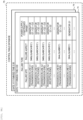
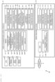
- Fig. 10 illustrates a configuration example of the contingency change result display screen 80 displayed on the display device 25 ( Fig. 1 ) by the display unit 54 ( Fig. 2 ) of the power system monitoring control apparatus 4 as described above.
- the contingency change result display screen 80 is configured to include a time zone designation area 81, a disaster information display area 82, an contingency change rule display area 83, an assumed disaster estimation result display area 84, a contingency change result display area 85, a system diagram display area 86, and a model display area 87.
- the time zone designation area 81 is provided with a date designation column 81A and a time zone designation column 81B, a date on which the content of the post-change contingency data 43 is desired to be checked can be selected in a pull-down method to be displayed in the date designation column 81A, and a start time of the time zone within the date on which the post-change contingency data 43 is desired to be checked can be selected in a pull-down method to be displayed in the time zone designation column 81B. It is noted that, in the following description, the time zone designated by the time zone designation area 81 will be referred to as an designated time zone.
- a list of disaster information 41 registered in the disaster information database 40 ( Fig. 3 ) for a designated time zone is displayed on the disaster information display area 82, and a list of the contingency change rules registered as the contingency change rule data 45 in the contingency change rule database 44 ( Fig. 2 ) is displayed on the contingency change rule display area 83.
- a list of the assumed disaster content for each contingency site in the designated time zone stored in the assumed disaster content estimation result database 62 is displayed on the assumed disaster estimation result display area 84, and a list of each contingency (the failure point and failure aspect) in the post-change designated time zone changed by the contingency changing unit 52 ( Fig. 2 ) is displayed on the contingency change result display area 85.
- a change column 85A corresponding to each post-change contingency is provided on the "list of the contingencies in the post-change designated time zone", and a check mark 85B is displayed in the change column 85A corresponding to the contingency (added in Fig. 10 ) changed from the original content.
- the operator can immediately recognize which contingency has been changed based on the check mark 85B.
- system diagram of the target power system is displayed on the system diagram display area 86, and models such as symbols in the system diagram are displayed on the model display area 87.
- the operator can easily recognize the positions of the disaster occurrence points and the contingency points based on system diagrams and models.
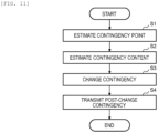
- Fig. 11 illustrates a flow of a series of processes (hereinafter, referred to as first power system monitoring control processes) executed by the power system monitoring control apparatus 4 to update the control table 76 retained by the system stabilization system 3 as described above.
- first power system monitoring control processes executed by the power system monitoring control apparatus 4 to update the control table 76 retained by the system stabilization system 3 as described above.
- the contingency point estimation unit 50 ( Fig. 2 ) estimates the occurrence point (contingency point) of the failure assumed to occur in the target power system for each time zone, registers the estimation result as the contingency point estimation result data 61 in the contingency point estimation result database 60 ( Fig. 6 ), and outputs the contingency point estimation result data 61 to the assumed disaster content estimation unit 51 ( Fig. 2 ) (S1).
- the contingency point estimation unit 50 extracts all the "disaster points" included in the disaster information 41 based on the disaster information 41 ( Fig. 3 ) for each time zone stored in the disaster information database 40 ( Fig. 1 ), registers the contingency point estimation result data 61 in which each extracted "disaster point” is designated as the contingency point in the contingency point estimation result database 60, and outputs the contingency point estimation result data 61 to the assumed disaster content estimation unit 51.
- the assumed disaster content estimation unit 51 ( Fig. 2 ) estimates the assumed disaster content at each contingency point for each time zone, registers the estimation result as the estimated disaster content estimation result data 63 in the assumed disaster content estimation result database 62, and outputs the estimated disaster content estimation result data 63 to the contingency changing unit 52 (S2).
- the assumed disaster content estimation unit 51 acquires the "disaster content" of each "disaster point" in the disaster information 41 for each time zone as the assumed disaster content of the corresponding contingency point based on the disaster information 41 ( Fig. 3 ) for each time zone stored in the disaster information database 40 ( Fig. 1 ). Then, the assumed disaster content estimation unit 51 generates the assumed disaster content estimation result data 63 described above with reference to Fig. 7 based on the acquired assumed disaster content of each contingency point, registers the generated assumed disaster content estimation result data 63 in the assumed disaster content estimation result database 62, and outputs the generated assumed disaster content estimation result data 63 to the contingency changing unit 52.
- the contingency changing unit 52 updates the contingency data 43 registered in the contingency database 42 based on the assumed disaster content estimation result data 63 provided from the assumed disaster content estimation unit 51 and each contingency change rule registered as the contingency change rule data 45 in the contingency change rule database 44 (S3).
- the contingency changing unit 52 sequentially compares each combination of the contingency point and the contingency content in the assumed disaster content estimation result data 63 with the combination of the disaster point and the disaster content of each contingency change rule for each time zone and extracts the contingency change content ("contingency change content" in Fig. 5 ) of the contingency change rule in which the combination of the contingency point and the contingency content match the combination of the disaster point and the disaster content.
- the contingency changing unit 52 extracts "4-line ground failure in the area A" as the contingency change content of the contingency change rule.
- the contingency changing unit 52 extracts "dropout of power supply 1 site in the area B", which is the contingency change content of the contingency change rule corresponding to the combination of the "area B" and “landslide” in Fig. 5 and "dropout of power supply 1 site in the area BC” which is the contingency change content of the contingency change rule corresponding to the combination of the "area C” and “tsunami".
- the contingency changing unit 52 generates the contingency change result data 65 by adding each contingency change content extracted as described above to the original contingency data 43 ( Fig. 4 ).
- the contingency change result data 65 is generated so as to add, to contingency data 43, simultaneous occurrence of 3-phase 6-line ground failures at the transmission ends of the transmission lines A1 and A2 (the failure site is "transmission line A1 (transmission end) + Transmission line A2 (transmission end)", and the row has a failure aspect of "3 ⁇ 6LG (ABCA'B'C' )" + “3 ⁇ 6LG (ABCA'B'C' ) "), dropout of power supply site B1 (the failure site is "power supply site B1", and the row has a failure aspect of "dropout”), and simultaneous dropout of power supply sites B1 and B2 (the failure site is "power supply site B1 + B2", and the row has a failure aspect of "drop
- the contingency changing unit 52 registers the contingency change result data 65 for each time zone generated as described above in the contingency change result database 64 and outputs the contingency change result data 65 to the post-change contingency transmission unit 53.
- the post-change contingency transmission unit 53 outputs the contingency change result data 65 to the system stabilization system 3 (S4), and a series of the first power system monitoring control process ends.
- the new updated control table 76 for each time zone is generated based on the contingency change result data 65 by the control table generation unit 74 ( Fig. 2 ) of the system stabilization system 3.
- control table 76 for each time zone generated in this manner overwrites the data of the control table 76 stored in the control table database 75, so that the control table 76 is updated.
- the contingency data 43 is changed according to the contingency change rule created by the operator (general power transmission and distribution business operator), and the contingency data (contingency change result data 65) including failures other than fixed failures is generated based on the post-change contingency data 43 to update the control table 76, and the control table 76 can be updated based on this contingency data.
- control table 76 can be created for a 4-equipment failure (N-4 failure) and a power supply 1 site dropout due to the occurrence of large-scale disasters such as earthquakes and tsunamis and rare frequent disasters as a target, a large-scale blackout can be prevented from occurring even during the occurrence of such a disaster.
- the supply reliability and resiliency of the power system can be improved while fulfilling the accountability.
- Fig. 12 in which components corresponding to those in Fig. 1 are denoted by the same reference numerals, illustrates a power system monitoring control system 90 according to a second embodiment.
- the power system monitoring control system 90 is configured to include a power system monitoring control apparatus 91 and a market management system 92 that are connected via the network 2 and a system stabilization system (not illustrated).
- the power system monitoring control apparatus 91 is a computer device having a function of updating the control table for each time zone in the same manner as in the first embodiment and calculating the state of the power system for each time zone based on the updated control table.
- the power system monitoring control apparatus 91 transmits the data of the updated control table for each time zone and the data (hereinafter, referred to as system state data) representing the calculated state of the power system for each time zone to the market management system 92.
- the power system monitoring control apparatus 91 is configured with a computer device having the CPU 20, the memory 21, the storage device 22, the communication device 23, the input device 24, and the display device 25.
- the memory 21 stores a control table generation program 100P, a system state calculation program 101P, a transmission program 102P, and a display program 103P in addition to the contingency point estimation program 50P, the assumed disaster content estimation program 51P, and the contingency changing program 52P.
- the storage device 22 of the power system monitoring control apparatus 91 stores a system data database 104, a control table database 105, and a system state data database 106 in addition to the disaster information database 40, the contingency database 42, the contingency change rule database 44, the contingency point estimation result database 60, the assumed disaster content estimation result database 62, and the contingency change result database 64.
- the market management system 92 is a computer system that is installed in the power trading market and has a function of managing trading of a power product (hereinafter, referred to as a market product) in the power trading market.
- the market management system 92 is also provided with a function of calculating the adjustment capability to be procured from the power trading market for each time zone by the operator (general power transmission and distribution business operator) who owns the power system monitoring control apparatus 91 as a procurement plan (hereinafter, referred to as an adjustment capability procurement plan) based on the updated control table for each time zone provided from the power system monitoring control apparatus 91, the system state data for each time zone, and the like and providing the calculated adjustment capability procurement plan to the operator.
- the market management system 92 is configured to include information processing resources such as a CPU 110, a memory 111 and a storage device 112. Since the configurations and functions of the CPU 110, the memory 111 and the storage device 112 are the same as the corresponding components (the CPU 10, the memory 11, and the storage device 12) of the system stabilization system 3 of the first embodiment described above with reference to Fig 1 , the description thereof will be omitted herein.
- information processing resources such as a CPU 110, a memory 111 and a storage device 112. Since the configurations and functions of the CPU 110, the memory 111 and the storage device 112 are the same as the corresponding components (the CPU 10, the memory 11, and the storage device 12) of the system stabilization system 3 of the first embodiment described above with reference to Fig 1 , the description thereof will be omitted herein.
- the memory 111 of the market management system 92 stores an adjustment capability procurement plan creation program 113P which will be described later.
- the storage device 112 of the market management system 92 stores a system data database 114, a control table database 115, a system state data database 116, a market data database 117, and an adjustment capability procurement plan database 118.
- Fig. 13 in which components corresponding to those in Fig. 2 are denoted by the same reference numerals, illustrates logical configurations of the power system monitoring control apparatus 91 and the market management system 92 according to the present embodiment.
- the power system monitoring control apparatus 91 is configured to include a contingency change input database group 120, a contingency changing unit 121, and a contingency change result database group 122.
- the contingency change input database group 120 is configured with the disaster information database 40, the contingency database 42, the contingency change rule database 44, and the system data database 104. Since the disaster information database 40, the contingency database 42, and the contingency change rule database 44 are databases having the configurations and contents as described above with reference to Figs. 3 to 5 , the description thereof will be omitted herein.
- system data database 104 is a database having the same configuration and contents as the system data database 72 ( Fig. 2 ) of the first embodiment, the description thereof will be omitted herein. It is noted that the system data 130 stored in the system data database 104 is data having the same content as the system data 73 stored in the system data database 72 of the first embodiment.
- the contingency changing unit 121 is configured with the contingency point estimation unit 50, the assumed disaster content estimation unit 51, the contingency changing unit 52, the control table generation unit 100, the system state calculation unit 101, the transmission unit 102, and the display unit 103.
- the contingency point estimation unit 50, the assumed disaster content estimation unit 51, and the contingency changing unit 52 are functional units having the respective functions described above.
- the control table generation unit 100 is a functional unit that is realized by the CPU 20 ( Fig. 12 ) of the power system monitoring control apparatus 91 executing the control table generation program 100P ( Fig. 12 ) stored in the memory 21 ( Fig. 12 ).
- the control table generation unit 100 generates the control table 131 for each time zone in the same manner as the control table generation unit 74 ( Fig. 2 ) of the first embodiment based on the contingency change result data 65 for each time zone provided from the contingency changing unit 52 and the system data 130 stored in the system data database 104. Then, the control table generation unit 100 stores the generated control table 131 in the control table database 105 and outputs the generated control table 131 to the system state calculation unit 101.
- control table 131 is a control table that is relaxed on the premise of using the system stabilization system.
- control table 131 is already stored in the control table database 105, and the control table generation unit 100 is assumed to generate a new updated control table 131 based on the contingency change result data 65 for each time zone provided from the contingency changing unit 52, to store the generated new control table 131 in the control table database 105 so as to overwrite the original control table 131, and to output the generated new control table 131 to the system state calculation unit 101.
- the system state calculation unit 101 is a functional unit that is realized by the CPU 20 of the power system monitoring control apparatus 91 executing the system state calculation program 101P ( Fig. 12 ) stored in the memory 21.
- the system state calculation unit 101 calculates the power for each time zone to be procured as the adjustment capability from the power trading market and the new operation standard for each transmission line at that time on the premise that the control of the corresponding control target registered in the updated control table 131 is executed during the occurrence of each contingency.
- the system state calculation unit 101 stores the calculated power to be procured for each time zone and the operation standard as the system state data 132 for each time zone in the system state data database 106 and outputs the system state data 132 and the data of the control table 131 for each time zone provided from the control table generation unit 100 to the transmission unit 102.
- the transmission unit 102 is a functional unit that is realized by the CPU 20 of the power system monitoring control apparatus 91 executing the transmission program 102P ( Fig. 12 ) stored in the memory 21.
- the transmission unit 102 transmits the system state data 132 for each time zone provided from the system state calculation unit 101 and the data of the control table 131 for each time zone to the market management system 92 via the communication device 23 ( Fig. 12 ).
- the display unit 103 is a functional unit that is realized by the CPU 20 of the power system monitoring control apparatus 91 executing the display program 103P ( Fig. 16 ) stored in the memory 21.
- the display unit 103 displays a predetermined screen including various information included in the contingency change result display screen 80 described above with reference to, for example Fig.
- the contingency change result database group 122 is configured with the contingency point estimation result database 60, the assumed disaster content estimation result database 62, the contingency change result database 64, the control table database 105, and the system state data database 106.
- each of the contingency point estimation result database 60, the assumed disaster content estimation result database 62, and the contingency change result database 64 has the configuration and contents as described above with reference to Figs. 6 to 8 , the description thereof will be omitted herein.
- the control table database 105 has the same configuration and contents as the control table database 76 ( Fig. 9A ) of the first embodiment, the description thereof will be omitted herein.
- the system state data database 106 is a database used for managing the system state data 132 for each time zone calculated by the system state calculation unit 101 as described above.
- the system state data 132 includes information (hereinafter, referred to as adjustment capability procurement power information) 132A on power for each time zone to be procured as the adjustment capability from the power trading market calculated by the system state calculation unit 101 as described above and information (hereinafter, referred to as transmission line information) 132B on a new operation standard for each time zone of each transmission line.
- adjustment capability procurement power information information
- transmission line information information
- the adjustment capability procurement power information 132A includes name information 132AA which is information on a name of a market product to be procured from the power trading market as adjustment capability in the corresponding time zone, procurement power information 132AB which is information on an amount of the market product to be procured, and unit price information 132AC which is information on a bid unit price of the corresponding market product.
- the transmission line information 132B includes transmission line name information 132BA which is information on a name of each transmission line and operation standard information 132BB which is information on a new relaxed operation standard for the transmission line.
- the market management system 92 includes the system data database 114, the control table database 115, the system state data database 116, the market data database 117, an adjustment capability procurement plan creation unit 113, and the adjustment capability procurement plan database 118.
- the system data database 114 is a database having the same configuration as the system data database 104 of the power system monitoring control apparatus 91.
- the system data database 114 stores the same system data 140 as the system data 130 stored in the system data database 104, and when the system data 130 of the system data database 104 is updated, the system data 140 of the system data database 114 is similarly updated in synchronization with the updating.
- the control table database 115 and the system state data database 116 also have the same configurations as the control table database 105 and the system state data database 106 of the power system monitoring control apparatus 91, respectively, and store the control table 141 and the system state data 142 transmitted from the power system monitoring control apparatus 91, respectively.
- the market data database 117 stores bid information for each market product for each time zone as market data 143.
- the adjustment capability procurement plan creation unit 113 is a functional unit that is realized by the CPU 110 ( Fig. 12 ) of the market management system 92 executing the adjustment capability procurement plan creation program 113P ( Fig. 12 ) stored in the memory 111 ( Fig. 2 ).
- the adjustment capability procurement plan creation unit 113 creates a power procurement plan (hereinafter, referred to as an adjustment capability procurement plan) 144 for each time zone to be procured from the power trading market as an adjustment capability based on system data 140 stored in the system data database 114, a control table 141 for each time zone stored in the control table database 115, system state data 142 for each time zone stored in the system state data database 116, and market data 143 stored in the market data database 117 and stores the created adjustment capability procurement plan 144 for each time zone in the adjustment capability procurement plan database 118.
- an adjustment capability procurement plan 144 for each time zone to be procured from the power trading market as an adjustment capability based on system data 140 stored in the system data database 114, a control table 141 for each time zone stored in the control table database 115, system state data 142 for each time zone stored in the system state data database 116, and market data 143 stored in the market data database 117 and stores the created adjustment capability procurement plan 144 for each time zone in the adjustment capability procurement plan
- the adjustment capability procurement plan database 118 is a database used for managing the adjustment capability procurement plan 144 for each time zone created by the adjustment capability procurement plan creation unit 113.
- the adjustment capability procurement plan 144 registered in the adjustment capability procurement plan database 118 is notified to the business operator (general power transmission and distribution business operator) who owns the power system monitoring control apparatus 91.
- the business operator procures power as an adjustment capability from the power trading market for each time zone according to this adjustment capability procurement plan 144.
- Fig. 15 illustrates a flow of a series of processes (hereinafter, referred to as second power system monitoring control processes) executed by the power system monitoring control apparatus 91 to generate or calculate the updated control table 131 for each time zone and the system state data 132 for each time zone as described above.
- second power system monitoring control processes executed by the power system monitoring control apparatus 91 to generate or calculate the updated control table 131 for each time zone and the system state data 132 for each time zone as described above.
- steps S10 to S12 are executed in the same manner as steps S1 to S3 of the first power system monitoring control process described above with reference to Fig. 11 by the contingency point estimation unit 50, the assumed disaster content estimation unit 51, and the contingency changing unit 52.
- control table generation unit 100 generates a new control table 131 for each time zone based on the contingency change result data 65 for each time zone provided from the contingency changing unit 52 and the system data 130 stored in the system data database 104, stores the generated control table 131 in the control table database 105, and outputs the generated control table 131 to the system state calculation unit 101 (S13).
- the system state calculation unit 101 calculates the power for each time zone to be procured from the power trading market as adjustment capability and the new operational standard of each transmission line on the premise that the control of the corresponding control target registered in the new control table 131 is executed when each contingency occurs, based on the new control table 131 for each time zone provided from the control table generation unit 100 and the system data 130 stored in the system data database 104.
- the "power for each time zone to be procured from the power market as an adjustment capability" can be calculated by using the amount of power procured from the power market as an objective function and using methods such as security constrained optimal power flow and security constrained economic dispatch which is an optimization calculation with system constraints during normal times and contingencies as constraints.
- system state calculation unit 101 stores the calculated power (procurement capacity) for each time zone and the new operation standard of each transmission line as the system state data 132 for each time zone in the system state data database 106 and outputs the system state data 132 for each time zone and the data of the control table 131 for each time zone provided from the control table generation unit 100 to the transmission unit 102 (S14).
- the transmission unit 102 outputs the system state data 132 for each time zone provided from the system state calculation unit 101 and the data of the control table 131 to the market management system 92 (S15), and the power system monitoring control process ends.
- the market management system 92 calculates the procurement plan for the adjustment capability based on the new relaxed control table 131, the system stability can be maintained by the system stabilization system even during the occurrence of a failure due to a disaster, and an inexpensive adjustment capability can be procured by using the new relaxed control table 131, so that the operation cost of the power system operator can be reduced.
- the operation standard information 132BB of the transmission line information 132B represents the relaxed operation standard calculated based on the relaxed control table and the procured power information 132AB of the adjustment capability procurement power information 132A represents the procured power that satisfies relaxed operation standard.
- the market management system 92 can calculate the procurement plan from an initial point with low procurement costs under relaxed conditions by using the operation standard of each transmission line and the procurement power of the market product as constraints and initial values and evaluating the system stability based on the new updated control table 131, more inexpensive adjustment capability can be procured.
- Fig. 16 in which components corresponding to those in Fig. 12 are denoted by the same reference numerals, illustrates a power system monitoring control system 150 according to the third embodiment.
- the power system monitoring control system 150 is configured to include a power system monitoring control apparatus 151 and a central power supply command system 152 which are connected via the network 2 and a system stabilization system (not illustrated).
- the power system monitoring control apparatus 151 is a computer device having functions of updating the control table and calculating the state of the power system for each time zone based on the updated control table.
- the power system monitoring control apparatus 151 transmits the data of the updated control table for each time zone and data (hereinafter, referred to as system state data) representing the calculated state of the power system for each time zone to the central power supply command system 152.
- the central power supply command system 152 is a system that has a function of formulating a supply/demand plan of a future power based on a past power demand, weather forecasts, or the like, adjusting the output of the generator according to the formulated supply/demand plan, and the like.
- the central power supply command system 152 of the present embodiment generates an adjustment capability triggering command for each time zone, for example, as to what degree of adjustment capability is triggered by using which generator based on the updated control table and the system state data for each time zone provided from the power system monitoring control apparatus 151 and triggers the required adjustment capability by adjusting the necessary output of the generator based on the generated adjustment capability triggering command.
- Fig. 17 in which components corresponding to those in Fig. 13 are denoted by the same reference numerals, illustrates logical configurations of the power system monitoring control apparatus 151 and the central power supply command system 152.
- the power system monitoring control apparatus 151 has the same configuration as the power system monitoring control apparatus 91 ( Fig. 13 ) of the second embodiment except for the contents of a system state calculation unit 161 of a contingency changing unit 160 and system state data 164 stored in a system state data database 163 of a contingency change result database group 162.
- the system state calculation unit 161 is a functional unit that is realized by the CPU 20 ( Fig. 16 ) of the power system monitoring control apparatus 151 executing a system state calculation program 161P ( Fig. 16 ) stored in the memory 21 ( Fig. 16 ).
- the system state calculation unit 161 calculates the generated power of each generator to be output as the adjustment capability for each time zone and the new operation standard of each transmission line for each time zone on the premise that the control of the corresponding control target registered in the updated control table 131 ( Fig. 17 ) is executed during the occurrence of each contingency.
- the system state calculation unit 161 stores the calculated six powers for each time zone and operation standard as the system state data 164 for each time zone in the system state data database 163 and outputs the system state data 164 for each time zone and the data of the control table 131 for each time zone provided from the control table generation unit 100 to the transmission unit 102.
- the data of the control table 131 for each time zone and the system state data 154 for each time zone are transmitted from the transmission unit 102 to the central power supply command system 152.
- the display unit 165 is a functional unit that is realized by the CPU 20 of the power system monitoring control apparatus 151 executing a display program 165P ( Fig. 16 ) stored in the memory 21.
- the display unit 165 displays a predetermined screen including various information included in the contingency change result display screen 80 described above with reference to, for example Fig.
- the configuration of the system state data 164 of the present embodiment is illustrated in Fig. 18 .
- the system state data 164 of the present embodiment includes information (hereinafter, referred to as generator information) 164A on the output power of each generator to be output as the adjustment capability for each time zone calculated by the system state calculation unit 161 and transmission line information 164B.
- the generator information 164A includes name information 164AA which is information on the name of the generator of which output is to be controlled so as to generate the adjustment capability in the corresponding time zone, and output information 164AB which is to be output as the procurement power from the generator, and price information 164AC which is information on the fuel cost (fuel cost per unit power) required to output the power of 1 kWh from the corresponding generator.
- the transmission line information 164B includes transmission line name information 164BA which is information on the name of each transmission line, and operation standard information 164BB which is information on the new relaxed operation standard for the transmission line.
- the central power supply command system 152 is configured to include a system data database 114, a control table database 115, a system state data database 170, a demand forecast data database 171, a power generation/demand plan data database 172, an adjustment capability procurement result data database 173, a supply/demand plan creation unit 174, an adjustment capability triggering command value calculation unit 175, a supply/demand plan database 176, and an adjustment capability triggering command value database 177.
- the system data database 114 is a database having the same configuration as the system data database 104 of the power system monitoring control apparatus 151.
- the system data database 114 stores the same system data 140 as the system data 130 stored in the system data database 104, and when the system data 130 of the system data database 104 is updated, the system data 140 of the system data database 114 is also similarly updated in synchronization with the updating.
- the control table database 115 and the system state data database 170 are also databases having the same configurations as the control table database 105 and the system state data database 163 of the power system monitoring control apparatus 151, respectively, and the control table 141 and system state data 180 transmitted from the power system monitoring control apparatus 151 are stored, respectively.
- the demand forecast data database 171 stores demand forecast data 181 which is a power demand prediction result calculated in advance in each future time zone based on past performance and weather forecasts.
- the power generation/demand plan data database 172 stores a power generation plan and a demand plan for each future time zone submitted by a power generation company, a power retailer, a balancing group, a resource aggregator, or the like as power generation/demand plan data 182.
- the adjustment capability procurement result data database 173 stores adjustment capability procurement result data 183 representing the procurement result of the adjustment capability so far.
- the supply/demand plan creation unit 174 is a functional unit that is realized by the CPU 110 ( Fig. 16 ) of the central power supply command system 152 executing a supply/demand plan creation program 174P stored in the memory 111 ( Fig. 16 ).
- the supply/demand plan creation unit 174 creates a supply/demand plan 178 that is a plan of demand and supply for each future time zone based on the system data 140 stored in the system data database 114, the control tables 141 for each time zone stored in the control table database 115, the system state data 180 for each time zone stored in the system state data database 170, and the demand forecast data 181 stored in the demand forecast data database 171, stores the created supply/demand plan 178 in the supply/demand plan database 176.
- the adjustment capability triggering command value calculation unit 175 is a functional unit that is realized by the CPU 110 ( Fig. 16 ) of the central power supply command system 152 executing an adjustment capability triggering command value calculation program 175P stored in the memory 111 ( Fig. 16 ).
- the adjustment capability triggering command value calculation unit 175 calculates an adjustment capability command value (hereinafter, referred to as an adjustment capability triggering command value) 179 to be actually triggered for each future time zone based on the supply/demand plan 178 for each time zone created by the supply/demand plan creation unit 174, the power generation/demand plan data 182 stored in the power generation/demand plan data database 172, and the adjustment capability procurement result data 183 stored in the adjustment capability procurement result data database 173 and stores the calculated adjustment capability triggering command value 179 in the adjustment capability triggering command value database 177 for each time zone.
- an adjustment capability triggering command value (hereinafter, referred to as an adjustment capability triggering command value) 179 to be actually triggered for each future time zone based on the supply/demand plan 178 for each time zone created by the supply/demand plan creation unit 174, the power generation/demand plan data 182 stored in the power generation/demand plan data database 172, and the adjustment capability procurement result data 183 stored in the adjustment capability procurement result data database 173 and stores the calculated adjustment
- the supply/demand plan database 176 is a database used for managing the supply/demand plan for each time zone created by the supply/demand plan creation unit 174 as described above. After that, the supply/demand plan 178 stored in the supply/demand plan database 176 is used for controlling the output power of each generator.
- the adjustment capability triggering command value database 177 is a database used for managing the adjustment capability triggering command value 179 for each future time zone calculated by the adjustment capability triggering command value calculation unit 175 as described above. In accordance with the adjustment capability triggering command value 179 stored in the adjustment capability triggering command value database 177, output control of the corresponding generator for triggering the adjustment capability for each future time zone is performed by the central power supply command system 152.
- the system stability can be maintained by the system stabilization system during the occurrence of a system failure due to a disaster so as to calculate the supply plan and the adjustment capability triggering command value for each generator based on the control table stored in the control table database of the power system monitoring control apparatus, and also, the supply plan can be formulated and the adjustment capability can be triggered by using more inexpensive generators, so that the operation costs can be reduced.
- the operation standard information 164BB for each transmission line represents the operation standard relaxed by the updated control table 131 ( Fig. 17 ), and the output information 164AB of the generator information 164A represents the state of the generator that satisfies the operation standard relaxed by the updated control table 131.
- the central power supply command system 152 sets the operation standard and the generator state as constraints and initial values and evaluates the system stability based on the relaxed control table 131, so that the supply/demand plan 178 ( Fig. 17 ) and the adjustment capability triggering command value 179 ( Fig. 17 ) can be calculated from the initial point with a low fuel cost under the relaxed constraints, and thus, the supply/demand plan can be formulated and the adjustment capability can be triggered by using more inexpensive generator.
- the power system monitoring control apparatus 4 is allowed to be provided separately from the system stabilization system 3, the market management system 92, or the central power supply command system 152 has been described, but the present invention is not limited thereto. All the functions of the power system monitoring control apparatus 4 may be allowed to be installed in the system stabilization system 3, the market management system 92, or the power supply command system 152, and a portion of the functions of the power system monitoring control apparatus 4 may be allowed to be installed in the system stabilization system, the market management system 92, or a power supply command system 1523.
- the disaster information 41 is allowed to include information on both the occurrence point and content of the disaster has been described, but the present invention is not limited thereto, and only one of the information of the occurrence point and content of the disaster may be allowed to be included.
- the contingency change rule is allowed to include information on both the disaster point and disaster content and information on the contingency change content has been described, but the present invention is not limited thereto, only one information on the disaster point and the disaster content may be allowed to include the information on the contingency change content.
- the adjustment capability procurement plan creation unit 113 of the market management system 92 is allowed to procure the adjustment capability only from the power trading market
- the present invention is limited thereto, and in addition to procurement of adjustment capability from the power trading market, the adjustment capability may be allowed to be procured by controlling the output of the generator.
- the adjustment capability triggering command value calculation unit 175 of the central power supply command system 152 is allowed to procure the adjustment capability by controlling the output of the generator.
- the present invention is not limited thereto, and in addition to the output control of the generator, the adjustment capability may be allowed to be procured from the power trading market.
- the present invention can be widely applied to power system monitoring control systems of various configurations including system stabilization systems.
Landscapes
- Engineering & Computer Science (AREA)
- Business, Economics & Management (AREA)
- Human Resources & Organizations (AREA)
- Economics (AREA)
- General Physics & Mathematics (AREA)
- Physics & Mathematics (AREA)
- Strategic Management (AREA)
- Tourism & Hospitality (AREA)
- Power Engineering (AREA)
- Entrepreneurship & Innovation (AREA)
- Theoretical Computer Science (AREA)
- Marketing (AREA)
- General Business, Economics & Management (AREA)
- Health & Medical Sciences (AREA)
- Quality & Reliability (AREA)
- Operations Research (AREA)
- Automation & Control Theory (AREA)
- Game Theory and Decision Science (AREA)
- Educational Administration (AREA)
- Development Economics (AREA)
- Public Health (AREA)
- Water Supply & Treatment (AREA)
- General Health & Medical Sciences (AREA)
- Primary Health Care (AREA)
- Supply And Distribution Of Alternating Current (AREA)
- Remote Monitoring And Control Of Power-Distribution Networks (AREA)
- Management, Administration, Business Operations System, And Electronic Commerce (AREA)
Applications Claiming Priority (2)
| Application Number | Priority Date | Filing Date | Title |
|---|---|---|---|
| JP2020114285A JP7544518B2 (ja) | 2020-07-01 | 2020-07-01 | 電力系統監視制御システム及び方法 |
| PCT/JP2021/017170 WO2022004116A1 (ja) | 2020-07-01 | 2021-04-30 | 電力系統監視制御システム及び方法 |
Publications (2)
| Publication Number | Publication Date |
|---|---|
| EP4178073A1 true EP4178073A1 (de) | 2023-05-10 |
| EP4178073A4 EP4178073A4 (de) | 2024-07-24 |
Family
ID=79315767
Family Applications (1)
| Application Number | Title | Priority Date | Filing Date |
|---|---|---|---|
| EP21834669.0A Pending EP4178073A4 (de) | 2020-07-01 | 2021-04-30 | System und verfahren zur überwachung und steuerung eines stromversorgungssystems |
Country Status (4)
| Country | Link |
|---|---|
| US (1) | US12613519B2 (de) |
| EP (1) | EP4178073A4 (de) |
| JP (1) | JP7544518B2 (de) |
| WO (1) | WO2022004116A1 (de) |
Families Citing this family (2)
| Publication number | Priority date | Publication date | Assignee | Title |
|---|---|---|---|---|
| WO2025231049A1 (en) * | 2024-04-30 | 2025-11-06 | Resilient Entanglement, Inc. | Systems and methods for quantum-ai-based energy management in power systems |
| WO2026084203A1 (ko) * | 2024-10-18 | 2026-04-23 | 에이치디한국조선해양 주식회사 | Mvdc전기추진선박의 전력계통 보호 방법 및 그 장치 |
Family Cites Families (20)
| Publication number | Priority date | Publication date | Assignee | Title |
|---|---|---|---|---|
| JP5088628B2 (ja) | 2008-07-09 | 2012-12-05 | 清水建設株式会社 | 停電評価装置 |
| JP5501700B2 (ja) * | 2009-09-09 | 2014-05-28 | 三菱重工業株式会社 | 被災範囲推定装置及びプログラム |
| KR101030593B1 (ko) | 2009-09-29 | 2011-04-21 | 한국전력공사 | 거리 계전 장치, 거리 계전 처리 시스템 및 거리 계전 처리 방법 |
| JP5542398B2 (ja) * | 2009-09-30 | 2014-07-09 | 株式会社日立製作所 | 障害の根本原因解析結果表示方法、装置、及びシステム |
| KR20120058617A (ko) * | 2009-11-04 | 2012-06-07 | 가부시키가이샤 엔.티.티.도코모 | 재해 정보 제공 시스템 및 재해 정보 제공 방법 |
| JP5616311B2 (ja) | 2011-10-31 | 2014-10-29 | 株式会社日立製作所 | 系統安定化システム及び系統安定化方法 |
| US20150169024A1 (en) | 2012-06-17 | 2015-06-18 | Nation-E Ltd | Disaster recovery system and method |
| JP6129719B2 (ja) | 2013-11-13 | 2017-05-17 | 東北電力株式会社 | 送電線雷故障位置標定方法及びシステム |
| JP6173946B2 (ja) | 2014-02-28 | 2017-08-02 | 株式会社日立製作所 | 電力系統監視装置、電力系統制御装置及び電力系統監視方法 |
| CN103942729A (zh) * | 2014-04-15 | 2014-07-23 | 国网辽宁省电力有限公司沈阳供电公司 | 一种基于最小配电区域的城市配电网灾害风险评估方法 |
| AU2014404749A1 (en) * | 2014-08-26 | 2017-01-12 | Swiss Reinsurance Company Ltd. | Disaster risk management and financing system, and corresponding method thereof |
| JP6498894B2 (ja) * | 2014-09-16 | 2019-04-10 | 株式会社東芝 | 系統安定化システム |
| WO2016051958A1 (ja) * | 2014-09-30 | 2016-04-07 | 日本電気株式会社 | 電力管理装置、電力管理方法、電力管理システム、及び、プログラム |
| CN104915787A (zh) | 2015-06-23 | 2015-09-16 | 广州供电局有限公司 | 设备故障率修正及配电网可靠性评估的方法及系统 |
| JP6967364B2 (ja) * | 2017-04-07 | 2021-11-17 | 株式会社日立製作所 | 電力系統安定化装置および電力系統安定化方法 |
| JP6779171B2 (ja) * | 2017-04-27 | 2020-11-04 | 株式会社日立製作所 | 運用支援装置及び運用支援方法 |
| JP7018287B2 (ja) | 2017-10-06 | 2022-02-10 | 株式会社日立製作所 | 市場対応信頼度管理装置及び市場対応信頼度管理システム |
| WO2019143386A1 (en) * | 2018-01-17 | 2019-07-25 | Siemens Aktiengesellschaft | Autonomous restoration of power systems after natural disasters |
| CN109919409B (zh) | 2019-01-08 | 2020-09-25 | 中国南方电网有限责任公司超高压输电公司检修试验中心 | 一种变电站或换流站耦连回路地震风险评估方法 |
| JP7514748B2 (ja) * | 2020-12-04 | 2024-07-11 | 株式会社日立製作所 | 電力系統運用計画作成支援装置および方法 |
-
2020
- 2020-07-01 JP JP2020114285A patent/JP7544518B2/ja active Active
-
2021
- 2021-04-30 EP EP21834669.0A patent/EP4178073A4/de active Pending
- 2021-04-30 WO PCT/JP2021/017170 patent/WO2022004116A1/ja not_active Ceased
- 2021-04-30 US US17/998,312 patent/US12613519B2/en active Active
Also Published As
| Publication number | Publication date |
|---|---|
| US20230221716A1 (en) | 2023-07-13 |
| EP4178073A4 (de) | 2024-07-24 |
| JP7544518B2 (ja) | 2024-09-03 |
| WO2022004116A1 (ja) | 2022-01-06 |
| US12613519B2 (en) | 2026-04-28 |
| JP2022012452A (ja) | 2022-01-17 |
Similar Documents
| Publication | Publication Date | Title |
|---|---|---|
| US9293920B2 (en) | Systems and methods for synchronizing switching within a power distribution network | |
| Li et al. | Probability-based seismic resilience assessment method for substation systems | |
| Golari et al. | Two-stage stochastic optimal islanding operations under severe multiple contingencies in power grids | |
| EP4178073A1 (de) | System und verfahren zur überwachung und steuerung eines stromversorgungssystems | |
| Qorbani et al. | Long term transmission expansion planning to improve power system resilience against cascading outages | |
| EP3136530A1 (de) | Vorrichtung und verfahren zur überwachung der spannungsstabilität | |
| Ameli et al. | Reliability analysis and role of energy storage in resiliency of energy systems | |
| JP2023171430A (ja) | 優先度算出装置および優先度算出プログラム | |
| Kizito et al. | Stochastic optimization of distributed generator location and sizing in an islanded utility microgrid during a large-scale grid disturbance | |
| JP2025001037A (ja) | 停電リスク評価システムおよび停電リスク評価方法 | |
| Baca et al. | Use of advanced microgrids to support community resilience | |
| WO2026056425A1 (zh) | 一种电力系统弹性规划方案多要素效益分析方法及系统 | |
| Jardim et al. | Brazilian system operator online security assessment system | |
| Iakubovskii et al. | A model for power shortage minimization in electric power systems given constraints on controlled sections | |
| Khadka et al. | Agglomerative hierarchical clustering methodology to restore power system considering reactive power balance and stability factor analysis | |
| Du et al. | Resilience optimization analysis of smart mining cluster cyber-physical systems based on the NK model | |
| Li et al. | On‐line voltage security assessment and control | |
| Hong et al. | Enhancement of operational resilience with the online weather look-ahead study | |
| Song et al. | Method for assessing the functionality of substations subjected to earthquakes based on network power flow analysis | |
| Öner et al. | Improving resiliency of power grids during extreme events | |
| Bhatt et al. | Dynamic scheduling of operating energy and reserve in electricity market with ramp rate constraints | |
| Ahmad et al. | Contingency analysis and reliability evaluation of Bangladesh power system | |
| US20250286373A1 (en) | Planned power system operation device and planned power system operation method | |
| Monken | Interdependency Effects on the Electricity Grid Following a “Black Sky” Hazard | |
| Zhou et al. | A Function-Based Simulation Generalized Framework to Model Seismic Resilience of Interdependent Critical Infrastructure Systems |
Legal Events
| Date | Code | Title | Description |
|---|---|---|---|
| STAA | Information on the status of an ep patent application or granted ep patent |
Free format text: STATUS: THE INTERNATIONAL PUBLICATION HAS BEEN MADE |
|
| PUAI | Public reference made under article 153(3) epc to a published international application that has entered the european phase |
Free format text: ORIGINAL CODE: 0009012 |
|
| STAA | Information on the status of an ep patent application or granted ep patent |
Free format text: STATUS: REQUEST FOR EXAMINATION WAS MADE |
|
| 17P | Request for examination filed |
Effective date: 20221115 |
|
| AK | Designated contracting states |
Kind code of ref document: A1 Designated state(s): AL AT BE BG CH CY CZ DE DK EE ES FI FR GB GR HR HU IE IS IT LI LT LU LV MC MK MT NL NO PL PT RO RS SE SI SK SM TR |
|
| DAV | Request for validation of the european patent (deleted) | ||
| DAX | Request for extension of the european patent (deleted) | ||
| A4 | Supplementary search report drawn up and despatched |
Effective date: 20240624 |
|
| RIC1 | Information provided on ipc code assigned before grant |
Ipc: G06Q 10/20 20230101ALI20240618BHEP Ipc: G06Q 10/06 20230101ALI20240618BHEP Ipc: H02J 3/00 20060101ALI20240618BHEP Ipc: G06Q 50/06 20120101ALI20240618BHEP Ipc: H02J 13/00 20060101AFI20240618BHEP |