EP4178113A1 - Fahrzeugverkleidungsplatte mit einer schaltfunktion - Google Patents
Fahrzeugverkleidungsplatte mit einer schaltfunktion Download PDFInfo
- Publication number
- EP4178113A1 EP4178113A1 EP21383002.9A EP21383002A EP4178113A1 EP 4178113 A1 EP4178113 A1 EP 4178113A1 EP 21383002 A EP21383002 A EP 21383002A EP 4178113 A1 EP4178113 A1 EP 4178113A1
- Authority
- EP
- European Patent Office
- Prior art keywords
- light transmitting
- front panel
- light
- vehicle trim
- switching function
- Prior art date
- Legal status (The legal status is an assumption and is not a legal conclusion. Google has not performed a legal analysis and makes no representation as to the accuracy of the status listed.)
- Granted
Links
Images

Classifications
-
- B—PERFORMING OPERATIONS; TRANSPORTING
- B60—VEHICLES IN GENERAL
- B60Q—ARRANGEMENT OF SIGNALLING OR LIGHTING DEVICES, THE MOUNTING OR SUPPORTING THEREOF OR CIRCUITS THEREFOR, FOR VEHICLES IN GENERAL
- B60Q3/00—Arrangement of lighting devices for vehicle interiors; Lighting devices specially adapted for vehicle interiors
- B60Q3/80—Circuits; Control arrangements
- B60Q3/82—Switches specially adapted for vehicle interior lighting, e.g. switching by tilting the lens
-
- B—PERFORMING OPERATIONS; TRANSPORTING
- B60—VEHICLES IN GENERAL
- B60R—VEHICLES, VEHICLE FITTINGS, OR VEHICLE PARTS, NOT OTHERWISE PROVIDED FOR
- B60R13/00—Elements for body-finishing, identifying, or decorating; Arrangements or adaptations for advertising purposes
- B60R13/02—Internal Trim mouldings ; Internal Ledges; Wall liners for passenger compartments; Roof liners
-
- H—ELECTRICITY
- H03—ELECTRONIC CIRCUITRY
- H03K—PULSE TECHNIQUE
- H03K17/00—Electronic switching or gating, i.e. not by contact-making and –breaking
- H03K17/94—Electronic switching or gating, i.e. not by contact-making and –breaking characterised by the way in which the control signals are generated
- H03K17/96—Touch switches
- H03K17/962—Capacitive touch switches
-
- B—PERFORMING OPERATIONS; TRANSPORTING
- B60—VEHICLES IN GENERAL
- B60Q—ARRANGEMENT OF SIGNALLING OR LIGHTING DEVICES, THE MOUNTING OR SUPPORTING THEREOF OR CIRCUITS THEREFOR, FOR VEHICLES IN GENERAL
- B60Q3/00—Arrangement of lighting devices for vehicle interiors; Lighting devices specially adapted for vehicle interiors
- B60Q3/20—Arrangement of lighting devices for vehicle interiors; Lighting devices specially adapted for vehicle interiors for lighting specific fittings of passenger or driving compartments; mounted on specific fittings of passenger or driving compartments
- B60Q3/233—Seats; Arm rests; Head rests
-
- B—PERFORMING OPERATIONS; TRANSPORTING
- B60—VEHICLES IN GENERAL
- B60Q—ARRANGEMENT OF SIGNALLING OR LIGHTING DEVICES, THE MOUNTING OR SUPPORTING THEREOF OR CIRCUITS THEREFOR, FOR VEHICLES IN GENERAL
- B60Q3/00—Arrangement of lighting devices for vehicle interiors; Lighting devices specially adapted for vehicle interiors
- B60Q3/60—Arrangement of lighting devices for vehicle interiors; Lighting devices specially adapted for vehicle interiors characterised by optical aspects
- B60Q3/62—Arrangement of lighting devices for vehicle interiors; Lighting devices specially adapted for vehicle interiors characterised by optical aspects using light guides
-
- B—PERFORMING OPERATIONS; TRANSPORTING
- B60—VEHICLES IN GENERAL
- B60R—VEHICLES, VEHICLE FITTINGS, OR VEHICLE PARTS, NOT OTHERWISE PROVIDED FOR
- B60R13/00—Elements for body-finishing, identifying, or decorating; Arrangements or adaptations for advertising purposes
- B60R13/02—Internal Trim mouldings ; Internal Ledges; Wall liners for passenger compartments; Roof liners
- B60R13/0237—Side or rear panels
-
- F—MECHANICAL ENGINEERING; LIGHTING; HEATING; WEAPONS; BLASTING
- F21—LIGHTING
- F21S—NON-PORTABLE LIGHTING DEVICES; SYSTEMS THEREOF; VEHICLE LIGHTING DEVICES SPECIALLY ADAPTED FOR VEHICLE EXTERIORS
- F21S41/00—Illuminating devices specially adapted for vehicle exteriors, e.g. headlamps
- F21S41/20—Illuminating devices specially adapted for vehicle exteriors, e.g. headlamps characterised by refractors, transparent cover plates, light guides or filters
- F21S41/24—Light guides
-
- F—MECHANICAL ENGINEERING; LIGHTING; HEATING; WEAPONS; BLASTING
- F21—LIGHTING
- F21S—NON-PORTABLE LIGHTING DEVICES; SYSTEMS THEREOF; VEHICLE LIGHTING DEVICES SPECIALLY ADAPTED FOR VEHICLE EXTERIORS
- F21S41/00—Illuminating devices specially adapted for vehicle exteriors, e.g. headlamps
- F21S41/50—Illuminating devices specially adapted for vehicle exteriors, e.g. headlamps characterised by aesthetic components not otherwise provided for, e.g. decorative trim, partition walls or covers
-
- H—ELECTRICITY
- H01—ELECTRIC ELEMENTS
- H01Q—ANTENNAS, i.e. RADIO AERIALS
- H01Q1/00—Details of, or arrangements associated with, antennas
- H01Q1/12—Supports; Mounting means
- H01Q1/22—Supports; Mounting means by structural association with other equipment or articles
-
- H—ELECTRICITY
- H01—ELECTRIC ELEMENTS
- H01Q—ANTENNAS, i.e. RADIO AERIALS
- H01Q1/00—Details of, or arrangements associated with, antennas
- H01Q1/36—Structural form of radiating elements, e.g. cone, spiral, umbrella; Particular materials used therewith
- H01Q1/38—Structural form of radiating elements, e.g. cone, spiral, umbrella; Particular materials used therewith formed by a conductive layer on an insulating support
-
- B—PERFORMING OPERATIONS; TRANSPORTING
- B60—VEHICLES IN GENERAL
- B60R—VEHICLES, VEHICLE FITTINGS, OR VEHICLE PARTS, NOT OTHERWISE PROVIDED FOR
- B60R13/00—Elements for body-finishing, identifying, or decorating; Arrangements or adaptations for advertising purposes
- B60R13/02—Internal Trim mouldings ; Internal Ledges; Wall liners for passenger compartments; Roof liners
- B60R2013/0287—Internal Trim mouldings ; Internal Ledges; Wall liners for passenger compartments; Roof liners integrating other functions or accessories
-
- F—MECHANICAL ENGINEERING; LIGHTING; HEATING; WEAPONS; BLASTING
- F21—LIGHTING
- F21Y—INDEXING SCHEME ASSOCIATED WITH SUBCLASSES F21K, F21L, F21S and F21V, RELATING TO THE FORM OR THE KIND OF THE LIGHT SOURCES OR OF THE COLOUR OF THE LIGHT EMITTED
- F21Y2115/00—Light-generating elements of semiconductor light sources
- F21Y2115/10—Light-emitting diodes [LED]
-
- H—ELECTRICITY
- H03—ELECTRONIC CIRCUITRY
- H03K—PULSE TECHNIQUE
- H03K2217/00—Indexing scheme related to electronic switching or gating, i.e. not by contact-making or -breaking covered by H03K17/00
- H03K2217/94—Indexing scheme related to electronic switching or gating, i.e. not by contact-making or -breaking covered by H03K17/00 characterised by the way in which the control signal is generated
- H03K2217/96—Touch switches
- H03K2217/9607—Capacitive touch switches
-
- H—ELECTRICITY
- H03—ELECTRONIC CIRCUITRY
- H03K—PULSE TECHNIQUE
- H03K2217/00—Indexing scheme related to electronic switching or gating, i.e. not by contact-making or -breaking covered by H03K17/00
- H03K2217/94—Indexing scheme related to electronic switching or gating, i.e. not by contact-making or -breaking covered by H03K17/00 characterised by the way in which the control signal is generated
- H03K2217/96—Touch switches
- H03K2217/9607—Capacitive touch switches
- H03K2217/960755—Constructional details of capacitive touch and proximity switches
-
- H—ELECTRICITY
- H03—ELECTRONIC CIRCUITRY
- H03K—PULSE TECHNIQUE
- H03K2217/00—Indexing scheme related to electronic switching or gating, i.e. not by contact-making or -breaking covered by H03K17/00
- H03K2217/94—Indexing scheme related to electronic switching or gating, i.e. not by contact-making or -breaking covered by H03K17/00 characterised by the way in which the control signal is generated
- H03K2217/96—Touch switches
- H03K2217/9607—Capacitive touch switches
- H03K2217/960785—Capacitive touch switches with illumination
- H03K2217/96079—Capacitive touch switches with illumination using a single or more light guides
Definitions
- the present invention relates to a vehicle trim panel having a switching function comprising a decorative front panel which conceals a switching device having switching areas defined on the decorative front panel for controlling vehicle functions and a lighting device for backlighting said switching areas.
- the switching device comprises capacitive sensors.
- Proximity switches are proximity sensitive, that is they do not require mechanical movement. Therefore, the mere act of touching a switching area which function as touch sensor, effects the switch operation of the corresponding function associated to said switching area.
- the proximity switches do not require mechanical movement, they occupy a reduced space and they are easily integrated into vehicle trims.
- the decorative front panel forming the external surface of the vehicle trim conceals the switching device and at the same time acts as an actuating surface by the different switching areas defined on it.
- One way to do this is to provide a lighting device concealed by the front decorative panel in order to backlight said switching areas.
- switching areas commonly comprise light transmitting portions forming pictograms which the vehicle occupant can identify and touch in order to control the corresponding vehicle function associated to the corresponding switching area.
- the lighting device can comprise a light guide structure having individual light guiding channels which allow independently lighting each switching area.
- Said capacitive proximity switches comprise a plurality of antennas electrically connected to a corresponding capacitive sensor provided on a printed circuit board.
- Each antenna forms a sensing area which detects the proximity of a human body part, such as a finger, by the corresponding switching area provided on the decorative front panel, and generates a signal due to a change in capacitance value which is transmitted to the corresponding capacitive sensor configured to perform the corresponding switching function.
- each antenna has enough sensitivity to provide the switching operation when the vehicle occupant touches the corresponding switching area and the different signals affecting the different antennas do not interfere between them.
- both the centering and the proximity of the antennas avoiding the presence of air-gaps in relation to the corresponding switching area is important, the closer the antennas are to the switching areas configured in the decorative front panel, the better is the sensitivity of the antennas.
- Patent KR101985374 discloses a vehicle trim panel having a switching function comprising a decorative front panel having several switching areas and a touch sensor film forming an integral part of the decorative front panel.
- the touch sensor film forms an integral part of the decorative front panel where the switching areas are defined, both the centering and the proximity of the antennas regarding the switching areas are ensured during its manufacturing process. Thus, a correct operation of the different switching areas in terms of sensitivity can be ensured.
- a disadvantage of this configuration is derived from the difficulty or inability to separate the film and the decorative front panel.
- the integration of the film with the vehicle front panel increases the complexity of its manufacturing process and it is detrimental to the standardization of components.
- the film comprising the antennas could be provided as an independent component from the decorative front panel as for example JP4218660 discloses.
- each of the switching areas controls a particular vehicle function
- the object of the invention is a vehicle trim panel having a switching function comprising a decorative front panel which conceals a switching device for controlling vehicle functions and a lighting device for backlighting the switching areas defined on the decorative front panel wherein the switching device comprises several antennas printed on a common sensor film ensuring the relative position of the antennas regarding the decorative front panel and regarding the lighting device, and ensuring a permanent contact free of air-gaps between the sensor film and the decorative front panel in order to maximize its sensitivity, being the film and the decorative front panel easily separable from each other.
- the decorative front panel conceals a switching device comprising switching areas defined on the decorative front panel for controlling different vehicle functions and a lighting device for backlighting the switching areas.
- the vehicle trim provides a continuous external surface which improves its appearance, offering the vehicle occupant a more pleasant and harmonious environment inside the vehicle.
- the vehicle trim comprises a lighting device for individually illuminating each switching area.
- the vehicle occupant can interact with every single switching area in order to control the corresponding vehicle function associated to said switching area although the switching device is completely hidden by the front decorative panel.
- the switching device comprises several antennas provided on a common light transmitting film.
- the light can be transmitted to the decorative front panel in order to backlight the switching areas although said film is provided between the lighting device and the decorative front panel.
- the sensor foil further comprises an elastic rubber-like portion configured to be compressed between the back side of the decorative front panel and the front side of the light guide in order to keep the sensor foil in tight contact free of air-gaps with the back side of the decorative front panel.
- said elastic rubber-like portion comprises first attaching means configured to tightly and removably fit the sensor foil due to the elasticity of the elastic rubber-like portion either to the light guide according to a first main embodiment of the invention or to the decorative front panel according to a second main embodiment of the invention.
- the rubber-like portion allows reinforcing the sensor foil which makes easier its handling during the assembly process. In turn, said easy handling contributes to achieve an accurate assembly of the sensor foil.
- the particular configuration of the first attaching means allowing a press fitting type attachment due to the elasticity of the material they are formed, makes possible a quick and removable assembly process of the sensor foil.
- the sensor foil can be easily exchanged or repaired during the service life of the vehicle trim without damaging any component forming the assembly, and at the end of the service life of the vehicle trim, it improves the recycling of the whole assembly.
- this type of attachment avoids using adhesive as attaching means simplifying the tooling used during the assembly process of the whole assembly and avoiding the scrap produced due to errors during the gluing step.
- the manufacturing process of the decorative front panel is simplified, and the standardization of the sensor foil for different decorative front panel finishes, especially in the case in which the light transmitting film forms an integral part of the decorative front panel, is possible.
- the particular configuration of the attaching means together with the easy handling of the sensor foil allow an accurate assembly of the sensor foil either regarding the light guide according to a first main embodiment or regarding the decorative front panel according to a second main embodiment.
- the first main embodiment it is directly ensured the relative position between the sensing areas provided on the light transmitting film, including the printed antennas and the second light transmitting portions, and the corresponding light guiding channels, which makes it possible to ensure the individual illumination through each sensing area.
- the second main embodiment it is directly ensured the relative position between the sensing areas provided on the light transmitting film and the switching areas provided on the decorative front panel, which makes it possible to center the position of each antenna regarding the corresponding switching area which favours the sensitivity of each antenna.
- the elastic rubber-like portion is compressed between the back side of the decorative front panel and the front side of the light guide.
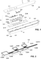
- Figure 1 shows an exploded view of the vehicle trim panel (10) having a switching function wherein the main parts forming the whole assembly can be distinguished, namely a decorative front panel (1), a lighting device (2) and a switching device (3).
- the decorative front panel (1) conceals the other parts forming the assembly. Thus, when the vehicle trim panel (10) is mounted in the vehicle, the vehicle occupant only can see the decorative front panel (1).
- the decorative front panel (1) comprises several switching areas (1.1), represented in figure 1 as windows delimited by dotted lines, through which the vehicle occupant can interact in order to control the particular vehicle function associated to each switching area (1.1).
- Every switching area (1.1) comprises a first light transmitting portion (1.11) defining a pictogram.
- the pictogram can be any figurative or symbolic drawing used for communication purposes, including alphanumeric characters.
- the first light transmitting portions (1.11) are positioned according to positions well-defined during the manufacturing process of the decorative front panel (1).
- the decorative front panel (1) has a front side (1.2) facing the vehicle interior cabin VC, and a back side (1.3), opposite to the front side (1.2).
- a light transmitting support (1.5) made of a transparent plastic material such as polycarbonate or Polymethyl methacrylate, which forms the main body of the decorative front panel (1) and provides the particular shape thereof.
- the decorative front panel (1) can further comprise a decorative film (1.7) mainly translucent which provides a decorative effect to the vehicle front panel (1) such as woody effect, a metallic effect or other decorative effects.
- a decorative film (1.7) mainly translucent which provides a decorative effect to the vehicle front panel (1) such as woody effect, a metallic effect or other decorative effects.
- the decorative front panel (1) further can comprise second attachment means (1.4) configured to connect it to the rest of the components forming the vehicle trim panel (1).
- second attachment means (1.4) provides a connection between the front decorative panel (1) and a back housing (4) described in detail below.
- the second attachment means (1.4) can comprise clips distributed around an edge (1.8) of the decorative front panel (1).
- Said edge (1.8) preferably comprises an opaque material in order to prevent light leakages outside the vehicle trim panel (10).
- the second attachment means (1.4) can be configured as a prolongation of said opaque edge (1.8) .
- the decorative front panel (1) can be manufactured for example by an injection molding process.
- the second main part forming the vehicle trim part (10) is the lighting device (2). It illuminates the pictograms through the first light transmitting portions (1.11) in order to inform the vehicle occupant on the possibilities of interaction with the individual switching areas (1.1).
- the lighting device (2) comprises in turn a printed circuit board (2.1) having several LEDs (2.2) configured each of them to illuminate a corresponding switching area (1.1).
- the LEDs (2.2) are positioned on a printed circuit board (2.1) according to positions well-defined during the manufacturing process of the printed circuit board (2.1).
- the printed circuit board (2.1) can comprise forth attachment means (2.11) in order to attach the printed circuit board (2.1) to a back housing (4) described in detail below, or to other vehicle component or other vehicle trim panel component which allows supporting the whole assembly.
- the lighting device (2) further comprises a light guide (2.3) defining individual light guiding channels (2.31) which allow independently lighting each switching area (1.1).
- the light guiding channels (2.31) comprise peripheral walls (2.311) which extend perpendicularly to the printed circuit board (2.1) delimiting said light guiding channels (2.31).
- the inner side of the peripheral walls (2.311) acts as a reflector guiding the light from each corresponding LED (2.2) to the corresponding sensing area (3.22) provided in the sensor foil (3.2) described below which in turn, is in correspondence with a switching area (1.1) provided in the decorative front panel (1).
- every light guiding channel (2.31) is in correspondence with a LED (2.2) at a first end (2.312), and in correspondence with a sensing area (3.22) at a second end (2.313).
- a light guiding channel (2.31) in turn can be divided into sub-channels (2.310).
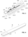
- the particular light guiding channel (2.31) in addition to having the peripheral walls (2.311) delimiting its outer contour, it also comprises dividing walls (2.312) defining the sub-channels (2.310) as figure 3 shows. According to this particular case, each sub-channel (2.310) is in correspondence with a corresponding LED (2.2).
- This particular case can be appropriate to define capacitive proximity switches activated by a sliding movement.
- the light guiding channels (2.31) forming the light guide (2.3) can be connected between them by first bridges (2.36), in order to configure the light guide (2.3) as a single part.
- the particular structure of the light guide (2.3) will depend on the particular distribution of the switching areas (1.1) over the decorative front panel (1) and their particular working.
- the light guide (2.3) has a front side (2.32) facing the decorative front panel (1) and a back side (2.33) facing the printed circuit board (2.1).
- the light guide (2.3) can comprise third attachment means (2.34) in order to attach the light guide (2.3) to the printed circuit board (2.1).
- said third attachment means can comprise clips.
- the light guide (2.3) can comprise a plastic part manufactured for example by an injection molding process.
- the last part forming the assembly is the switching device (3).
- It comprises several capacitive sensors (3.1), each of them affecting a particular switching area (1.1) provided in the decorative front panel (1). They can be provided in the same printed circuit board (2.1) as the LEDs (2.2) or in a further printed circuit board.
- the switching device (3) also comprises a sensor foil (3.2) having several independent sensing areas (3.22) configured on a light transmitting film (3.21).
- Each sensing area (3.22) comprises in turn, a printed antenna (3.221) on the light transmitting film (3.21) and electrically connected to a corresponding capacitive sensor (3.1), and a second light transmitting portion (3.222) formed by a portion of said light transmitting film (3.21).
- the light transmitting film (3.21) can comprise a tab (3.211) which receives the different electrical tracks (3.223) connected to the printed antennas (3.221).
- the free end (3.2111) of the tab (3.211) can comprise a plastic connector (3.25) part in order to provide both the electrical and the mechanical connection with the printed circuit board comprising the capacitive sensors (3.1).
- the printed antennas (3.221) are arranged surrounding the corresponding sensing area (3.22) in such a way that they enclose the second light transmitting portions (3.222).
- the light can pass through the sensing areas (3.22) even if the material forming the printed antennas (3.221) is opaque.
- the material forming the printed antennas (3.221) can be any conductive printable material such as a conductive ink.
- the conductive ink can be opaque or transparent.
- the material forming the light transmitting film (3.21) can be a plastic material such as polyethylene terephthalate (PET)or polyethylene (PE).
- PET polyethylene terephthalate
- PE polyethylene
- the light transmitting film (3.21) is milky white in order to diffuse the light passing through it.
- the light homogenization is improved.
- the light transmitting film (3.21) has a front side (3.212) facing the back side (1.3) of the front decorative panel (1) and a back side (3.213) facing the front side (2.33) of the light guide (3.2).
- the sensor foil (3.2) further comprises an elastic rubber-like portion (3.23) configured to be compressed between the back side (1.3) of the decorative front panel (1) and the front side (2.32) of the light guide (2.3) in the mounting position in order to keep the sensor foil (3.2) in tight contact free of air-gaps with the back side (1.3) of the decorative front panel (1) .
- the compression of the elastic rubber-like portion (3.23) when the sensor foil (3.2) is assembled is only intended to keep the sensor foil (2.3) in tight contact free of air-gaps with the decorative front panel (1), which means that said elastic rubber-like portion (3.23) does not have to compress when the vehicle occupant touches or presses the decorative panel (1) to activate the switching device (3).
- said elastic rubber-like portion (3.23) comprises first attaching means (3.231) configured to tightly and removably attach the sensor foil (2.3), due to the elasticity of the elastic rubber-like portion material, to either the light guide (2.3) or to the decorative front panel (1).
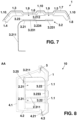
- the present invention defines two main embodiments, a first main embodiment represented in figures 1, 2 , 3 , 5 and 6 , in which the elastic rubber-like portion (3.23) is at the back side (3.213) of the light transmitting film (3.21) and the sensor foil (3.2) comprising said elastic rubber-like portion (3.23) is assembled on the light guide (2.3) and a second main embodiment represented in figures 7, and 8 , in which the elastic rubber-like portion (3.23) is at the front side (3.212) of the light transmitting film (3.21) and the sensor foil (3.2) comprising said elastic rubber-like portion (3.23) is assembled on the decorative front panel (1).
- the elastic rubber-like portion (3.23) and the light transmitting film (3.21) can be configured by over-moulding, or can be connected by any other attaching means such as an adhesive.
- both components configure a single part as figures 2 or 7 show, namely the sensor foil (3.2), which acts as a single part during the assembly process of the vehicle trim part (10) of the invention.
- the material forming the elastic rubber-like portion (3.23) can be silicone rubber.
- the main functions of the elastic rubber-like portion (3.23) in both embodiments are the same, namely it makes easier the handling of the sensor foil (3.2) during the assembly process, thereby contributing to achieve an accurate assembly of the sensor foil (2.3) in which the relative position of each sensing area (3.22) regarding either the corresponding light guiding channel (2.31) in the case of the first main embodiment or the corresponding switching area (1.1) in the case of the second main embodiment, is directly ensured.
- the elastic rubber-like portion (3.23) is at the back side (3.213) of the light transmitting film (3.21) and the sensor foil (3.2) comprising said elastic rubber-like portion (3.23) is assembled on the light guide (2.3).
- the elastic rubber-like portion (3.23) is made of an opaque material and it comprises a strip having a shape according to the outline of the light guide (2.3) in order to tightly attach the sensor foil (3.2) to the light guide (2.3). Said strip, configures the first attaching means (3.231).
- the outline of the light guide (2.3) is defined as the outer contour forming the light guide (2.3) and particularly, the peripheral walls (2.311) forming the light guiding channels (2.31). It means that the dividing walls (2.312) forming the sub-channels (2.310), if any, do not form part of the outline of the light guide (2.3). That is, the elastic rubber-like portion (3.23) by the first attaching means (3.231), is adapted to the outer contour forming the light guide (2.3) as figure 3 shows.
- the strip comprises a base portion (3.2311) contacting the front side (2.33) of the light guide (2.3) and the back side (3.213) of the light transmitting film (3.21) and a wing (3.2312) extended downwards and perpendicularly to the base portion (3.2311), in the direction of the peripheral walls (2.311) .
- Said wing (3.2312) being adjusted to the peripheral walls (2.311) forming the outline of the light guide (2.3)
- the strip further can comprise a light leakage prevention portion (3.2313) extended upwards and perpendicularly to the base portion (3.2311) as a prolongation of the wing (3.2312), wherein said light leakage prevention portion (3.2313) surrounds the edge of the light transmitting film (3.21) . In this way any possible light leakage occurring by the edge of the light transmitting film (3.21) is also prevented.
- the strip further comprises centering means which makes even easier the assembly of the sensor foil (3.2) in the light guide (2.3) according to the correct position of the sensing areas (3.22).
- the centering means can comprise an opening (3.232) provided in the strip, fitting a corresponding nose (2.3111) provided in a peripheral wall (2.311) forming the outline of the light guide (2.3).
- each light guiding channel (2.31) comprises at least a nose (2.3111) and the strip comprises the corresponding opening (3.232) for configuring the centering means.
- the elastic rubber-like portion (3.24) as figure 5 shows can comprise second bridges (3.233) connecting portions of the strip which affect to different light guiding channels (2.31) in order to configure the elastic rubber-like portion (3.24) as a single part.
- the elastic rubber-like portion (3.23) is at the front side (3.212) of the light transmitting film (3.21) and the sensor foil (3.2) comprising said elastic rubber-like portion (3.2) is assembled on the decorative front panel (1), particularly at its back side (1.3).
- the elastic rubber-like portion (3.23) is made of a light transmitting material and it comprises a main base (3.234) extended over the front side (3.212) of the light transmitting film (3.21) and several light transmitting protuberances (3.231), which form the first attaching means (3.231) in this case, emerging from said main base (3.234) and being in correspondence with the sensing areas (3.22).
- the light transmitting protuberances (3.231) collaborate with a corresponding attaching window (1.9) provided at the back side (1.3) of the decorative front panel (1) in order to attach the sensor foil (2.3) to the decorative front panel (1).
- the attaching windows (1.9) are configured according to the shape of said light transmitting protuberances (3.231) in order to tightly attach the sensor foil (3.2) to the decorative front panel (1), that is, the collaboration between the attaching windows (1.9) and the light transmitting protuberances (3.231) provides a press fitting type attachment due to the elasticity of the material of the elastic rubber-like portion (3.23). Therefore, each light transmitting protuberance (3.231) is deformed and compressed within the cavity formed by the corresponding attaching window (1.9).
- each light transmitting protuberance (3.231) is configured as an elevation to the vehicle interior cabin VC in relation to each sensing area (3.22), they allow the light passage from the light guiding channels (2.31) to the vehicle interior cabin VC through the decorative front panel (1).
- the light transmitting material forming the protuberances (3.231) can comprise additives that diffuse the light.
- the elastic rubber-like portion (3.24) as figure 8 shows can comprise second bridges (3.233) connecting portions of the elastic rubber-like portion (3.24) which affect to different light guiding channels (2.31) in order to configure the elastic rubber-like portion (3.24) as a single part.
- the attaching windows (1.9) are configured at the back side (1.3) of the decorative front panel (1).
- the decorative front panel (1) can comprise a light transmitting support (1.5) made of a transparent plastic material such as polycarbonate or Polymethyl methacrylate, which forms the main body of the decorative front panel (1) and provides the particular shape thereof and a mask (1.6) which defines the pictograms.
- a light transmitting support (1.5) made of a transparent plastic material such as polycarbonate or Polymethyl methacrylate, which forms the main body of the decorative front panel (1) and provides the particular shape thereof and a mask (1.6) which defines the pictograms.
- the attaching windows (1.9) are provided at the back side of the light transmitting support (1.5).
- they are formed as empty spaces provided in an opaque layer (1.10) configured at the back side of the light transmitting support (1.5).
- the decorative front panel (1) can further comprise a decorative film (1.7) mainly translucent which provides a decorative effect to the vehicle front panel (1) such as woody effect, a metallic effect or other decorative effects.
- a decorative film (1.7) mainly translucent which provides a decorative effect to the vehicle front panel (1) such as woody effect, a metallic effect or other decorative effects.
- the decorative front panel (1) further can comprise second attachment means (1.4) configured to connect it to the rest of the components forming the vehicle trim panel (1).
- the second attachment means (1.4) can comprise clips distributed around an edge (1.8) of the decorative front panel (1).
- Said edge (1.8) preferably comprises an opaque material in order to prevent light leakages outside the vehicle trim panel (10).
- the second attachment means (1.4) can be configured as a prolongation of said opaque edge (1.8).
- the front side (1.2) of the decorative front panel (1) can be a continuous surface or as figures 7 and 8 show, it can comprise recessed areas in correspondence with the switching areas (1.1)
- each switching area (1.1) is associated to the corresponding sensing area (3.22), the corresponding light guiding channel (2.31), the corresponding LED (2.2) and the corresponding capacitive sensor (3.1).
- the different switching areas (1.1) provided on the decorative front panel (1) can be firstly identified by the vehicle occupant and secondly they can be individually actuated in order to control the corresponding vehicle function associated to the corresponding switching area (1.1).
- the vehicle trim panel (10) further comprises a back housing (4) as for example figures 5 and 8 show.
- the back housing (4) can comprise a base (4.1) and a peripheral wing (4.2) extended upwards the base (4.1) .
- the peripheral wing (4.2) can comprise a supporting area (4.21) wherein an elastic sealing ring (4.3) rests in order to seal the whole assembly against dust and moisture.
- Said back housing (4) can comprise fifth attachment means (4.4) in order to attach the vehicle trim panel (1) to the vehicle.
- the elastic sealing ring (4.3) can comprise several force sensors (5) distributed along it and electrically connected to the capacitive sensors (3.1), for activating the switching device and in this way avoiding unintentional activation of the capacitive sensors (3.1) .
Landscapes
- Engineering & Computer Science (AREA)
- Mechanical Engineering (AREA)
- General Engineering & Computer Science (AREA)
- Switches That Are Operated By Magnetic Or Electric Fields (AREA)
- Arrangements Of Lighting Devices For Vehicle Interiors, Mounting And Supporting Thereof, Circuits Therefore (AREA)
Priority Applications (4)
| Application Number | Priority Date | Filing Date | Title |
|---|---|---|---|
| ES21383002T ES3019610T3 (en) | 2021-11-05 | 2021-11-05 | Vehicle trim panel having a switching function |
| EP21383002.9A EP4178113B1 (de) | 2021-11-05 | 2021-11-05 | Fahrzeugverkleidungsplatte mit einer schaltfunktion |
| CN202210898889.4A CN116080544B (zh) | 2021-11-05 | 2022-07-28 | 具有开关功能的车辆装饰面板 |
| US17/895,930 US12291146B2 (en) | 2021-11-05 | 2022-08-25 | Vehicle trim panel having a switching function |
Applications Claiming Priority (1)
| Application Number | Priority Date | Filing Date | Title |
|---|---|---|---|
| EP21383002.9A EP4178113B1 (de) | 2021-11-05 | 2021-11-05 | Fahrzeugverkleidungsplatte mit einer schaltfunktion |
Publications (2)
| Publication Number | Publication Date |
|---|---|
| EP4178113A1 true EP4178113A1 (de) | 2023-05-10 |
| EP4178113B1 EP4178113B1 (de) | 2025-01-22 |
Family
ID=78789931
Family Applications (1)
| Application Number | Title | Priority Date | Filing Date |
|---|---|---|---|
| EP21383002.9A Active EP4178113B1 (de) | 2021-11-05 | 2021-11-05 | Fahrzeugverkleidungsplatte mit einer schaltfunktion |
Country Status (4)
| Country | Link |
|---|---|
| US (1) | US12291146B2 (de) |
| EP (1) | EP4178113B1 (de) |
| CN (1) | CN116080544B (de) |
| ES (1) | ES3019610T3 (de) |
Citations (5)
| Publication number | Priority date | Publication date | Assignee | Title |
|---|---|---|---|---|
| JP4218660B2 (ja) | 2005-05-18 | 2009-02-04 | トヨタ紡織株式会社 | 車両用スイッチ装置 |
| US20110025643A1 (en) * | 2009-07-28 | 2011-02-03 | E.G.O. Elektro-Geraetebau Gmbh | Sensor element device |
| DE102016201861A1 (de) * | 2016-02-08 | 2017-08-10 | BSH Hausgeräte GmbH | Haushaltsgerät mit einer Bedienblende |
| KR101985374B1 (ko) | 2019-01-07 | 2019-06-03 | 주식회사 서연이화 | 자동차용 스마트 가니쉬 및 그 양산방법 |
| WO2020106573A1 (en) * | 2018-11-23 | 2020-05-28 | Yanfeng Global Automotive Interior Systems Co. Ltd | Vehicle interior component |
Family Cites Families (10)
| Publication number | Priority date | Publication date | Assignee | Title |
|---|---|---|---|---|
| WO2009036233A1 (en) * | 2007-09-12 | 2009-03-19 | Continental Automotive Systems Us, Inc. | Reconfigurable switch array using multi-layered film |
| US8330385B2 (en) * | 2010-02-15 | 2012-12-11 | Ford Global Technologies, Llc | Light bar |
| US20120280528A1 (en) * | 2011-05-06 | 2012-11-08 | Ford Global Technologies, Llc | Vehicle accent molding with puddle light |
| ES2759723T3 (es) * | 2015-02-04 | 2020-05-12 | Antolin Grupo Ing Sa | Conjunto decorativo luminoso para interior de vehículo |
| US9738219B1 (en) * | 2016-05-11 | 2017-08-22 | Ford Global Technologies, Llc | Illuminated vehicle trim |
| CN110267807A (zh) * | 2017-01-06 | 2019-09-20 | 上海延锋金桥汽车饰件系统有限公司 | 车辆内部部件 |
| DE102017217162A1 (de) * | 2017-09-27 | 2019-03-28 | Bayerische Motoren Werke Aktiengesellschaft | Interieurbaugruppe für ein Kraftfahrzeug und Verfahren zur Herstellung einer Interieurbaugruppe |
| US10427622B2 (en) * | 2017-12-28 | 2019-10-01 | Ford Global Technologies, Llc | Console with grounded trim ring |
| US10778223B2 (en) * | 2018-04-23 | 2020-09-15 | Ford Global Technologies, Llc | Hidden switch assembly |
| US10868532B2 (en) * | 2018-09-12 | 2020-12-15 | Ford Global Technologies, Llc | Vehicle trim assembly having sensor and grounded trim component |
-
2021
- 2021-11-05 ES ES21383002T patent/ES3019610T3/es active Active
- 2021-11-05 EP EP21383002.9A patent/EP4178113B1/de active Active
-
2022
- 2022-07-28 CN CN202210898889.4A patent/CN116080544B/zh active Active
- 2022-08-25 US US17/895,930 patent/US12291146B2/en active Active
Patent Citations (5)
| Publication number | Priority date | Publication date | Assignee | Title |
|---|---|---|---|---|
| JP4218660B2 (ja) | 2005-05-18 | 2009-02-04 | トヨタ紡織株式会社 | 車両用スイッチ装置 |
| US20110025643A1 (en) * | 2009-07-28 | 2011-02-03 | E.G.O. Elektro-Geraetebau Gmbh | Sensor element device |
| DE102016201861A1 (de) * | 2016-02-08 | 2017-08-10 | BSH Hausgeräte GmbH | Haushaltsgerät mit einer Bedienblende |
| WO2020106573A1 (en) * | 2018-11-23 | 2020-05-28 | Yanfeng Global Automotive Interior Systems Co. Ltd | Vehicle interior component |
| KR101985374B1 (ko) | 2019-01-07 | 2019-06-03 | 주식회사 서연이화 | 자동차용 스마트 가니쉬 및 그 양산방법 |
Also Published As
| Publication number | Publication date |
|---|---|
| ES3019610T3 (en) | 2025-05-20 |
| US20230145906A1 (en) | 2023-05-11 |
| CN116080544A (zh) | 2023-05-09 |
| US12291146B2 (en) | 2025-05-06 |
| CN116080544B (zh) | 2025-08-19 |
| EP4178113B1 (de) | 2025-01-22 |
Similar Documents
| Publication | Publication Date | Title |
|---|---|---|
| US5491313A (en) | Halo lighting for keypad switch assemblies | |
| US8648832B2 (en) | Touch sensor system and method | |
| US5718326A (en) | Backlit button/switchpad assembly | |
| CN105027036B (zh) | 用于方向盘的具有光学手指导航模块的操作装置 | |
| US10017977B2 (en) | Keyless entry assembly having capacitance sensor operative for detecting objects | |
| US20090301852A1 (en) | Integrated Switch or Integrated Button | |
| US20110057773A1 (en) | Keyless Entry Assembly Having Capacitance Sensor Operative for Detecting Objects | |
| US20170269774A1 (en) | Vehicle control device and manufacturing method | |
| CN208128217U (zh) | 接近开关组件 | |
| US12291146B2 (en) | Vehicle trim panel having a switching function | |
| CN112356786A (zh) | 触控软质内饰包覆产品及车辆 | |
| JP2001074358A (ja) | 冷蔵庫 | |
| CN113168982A (zh) | 装置以及操作装置 | |
| CN212213582U (zh) | 一种外壳一体化成型的料理机底座 | |
| US7434949B2 (en) | Illumination device | |
| KR102463695B1 (ko) | 차량용 입력기구 | |
| JP2004235037A (ja) | スイッチモジュール | |
| CN211118881U (zh) | 一种汽车氛围灯 | |
| KR200445702Y1 (ko) | 차량용 스위치 유니트 | |
| JP7579700B2 (ja) | スイッチ装置 | |
| CN217402377U (zh) | 一种车内阅读灯及汽车 | |
| CN220506569U (zh) | 用于车辆的灯装置 | |
| CN223237377U (zh) | 用于车辆的控制面板和具有该控制面板的车辆系统 | |
| US12600298B2 (en) | Conveyance interior part | |
| JP2004276876A (ja) | 照明ユニット |
Legal Events
| Date | Code | Title | Description |
|---|---|---|---|
| PUAI | Public reference made under article 153(3) epc to a published international application that has entered the european phase |
Free format text: ORIGINAL CODE: 0009012 |
|
| STAA | Information on the status of an ep patent application or granted ep patent |
Free format text: STATUS: THE APPLICATION HAS BEEN PUBLISHED |
|
| AK | Designated contracting states |
Kind code of ref document: A1 Designated state(s): AL AT BE BG CH CY CZ DE DK EE ES FI FR GB GR HR HU IE IS IT LI LT LU LV MC MK MT NL NO PL PT RO RS SE SI SK SM TR |
|
| STAA | Information on the status of an ep patent application or granted ep patent |
Free format text: STATUS: REQUEST FOR EXAMINATION WAS MADE |
|
| 17P | Request for examination filed |
Effective date: 20231102 |
|
| RBV | Designated contracting states (corrected) |
Designated state(s): AL AT BE BG CH CY CZ DE DK EE ES FI FR GB GR HR HU IE IS IT LI LT LU LV MC MK MT NL NO PL PT RO RS SE SI SK SM TR |
|
| GRAP | Despatch of communication of intention to grant a patent |
Free format text: ORIGINAL CODE: EPIDOSNIGR1 |
|
| STAA | Information on the status of an ep patent application or granted ep patent |
Free format text: STATUS: GRANT OF PATENT IS INTENDED |
|
| RIC1 | Information provided on ipc code assigned before grant |
Ipc: H03K 17/96 20060101AFI20240902BHEP |
|
| INTG | Intention to grant announced |
Effective date: 20240918 |
|
| GRAS | Grant fee paid |
Free format text: ORIGINAL CODE: EPIDOSNIGR3 |
|
| GRAA | (expected) grant |
Free format text: ORIGINAL CODE: 0009210 |
|
| STAA | Information on the status of an ep patent application or granted ep patent |
Free format text: STATUS: THE PATENT HAS BEEN GRANTED |
|
| AK | Designated contracting states |
Kind code of ref document: B1 Designated state(s): AL AT BE BG CH CY CZ DE DK EE ES FI FR GB GR HR HU IE IS IT LI LT LU LV MC MK MT NL NO PL PT RO RS SE SI SK SM TR |
|
| REG | Reference to a national code |
Ref country code: GB Ref legal event code: FG4D |
|
| REG | Reference to a national code |
Ref country code: CH Ref legal event code: EP |
|
| REG | Reference to a national code |
Ref country code: IE Ref legal event code: FG4D |
|
| REG | Reference to a national code |
Ref country code: DE Ref legal event code: R096 Ref document number: 602021025123 Country of ref document: DE |
|
| REG | Reference to a national code |
Ref country code: ES Ref legal event code: FG2A Ref document number: 3019610 Country of ref document: ES Kind code of ref document: T3 Effective date: 20250520 |
|
| REG | Reference to a national code |
Ref country code: NL Ref legal event code: MP Effective date: 20250122 |
|
| PG25 | Lapsed in a contracting state [announced via postgrant information from national office to epo] |
Ref country code: NL Free format text: LAPSE BECAUSE OF FAILURE TO SUBMIT A TRANSLATION OF THE DESCRIPTION OR TO PAY THE FEE WITHIN THE PRESCRIBED TIME-LIMIT Effective date: 20250122 |
|
| PG25 | Lapsed in a contracting state [announced via postgrant information from national office to epo] |
Ref country code: RS Free format text: LAPSE BECAUSE OF FAILURE TO SUBMIT A TRANSLATION OF THE DESCRIPTION OR TO PAY THE FEE WITHIN THE PRESCRIBED TIME-LIMIT Effective date: 20250422 |
|
| PG25 | Lapsed in a contracting state [announced via postgrant information from national office to epo] |
Ref country code: FI Free format text: LAPSE BECAUSE OF FAILURE TO SUBMIT A TRANSLATION OF THE DESCRIPTION OR TO PAY THE FEE WITHIN THE PRESCRIBED TIME-LIMIT Effective date: 20250122 |
|
| PG25 | Lapsed in a contracting state [announced via postgrant information from national office to epo] |
Ref country code: PL Free format text: LAPSE BECAUSE OF FAILURE TO SUBMIT A TRANSLATION OF THE DESCRIPTION OR TO PAY THE FEE WITHIN THE PRESCRIBED TIME-LIMIT Effective date: 20250122 |
|
| REG | Reference to a national code |
Ref country code: LT Ref legal event code: MG9D |
|
| PG25 | Lapsed in a contracting state [announced via postgrant information from national office to epo] |
Ref country code: IS Free format text: LAPSE BECAUSE OF FAILURE TO SUBMIT A TRANSLATION OF THE DESCRIPTION OR TO PAY THE FEE WITHIN THE PRESCRIBED TIME-LIMIT Effective date: 20250522 Ref country code: NO Free format text: LAPSE BECAUSE OF FAILURE TO SUBMIT A TRANSLATION OF THE DESCRIPTION OR TO PAY THE FEE WITHIN THE PRESCRIBED TIME-LIMIT Effective date: 20250422 |
|
| REG | Reference to a national code |
Ref country code: AT Ref legal event code: MK05 Ref document number: 1762227 Country of ref document: AT Kind code of ref document: T Effective date: 20250122 |
|
| PG25 | Lapsed in a contracting state [announced via postgrant information from national office to epo] |
Ref country code: HR Free format text: LAPSE BECAUSE OF FAILURE TO SUBMIT A TRANSLATION OF THE DESCRIPTION OR TO PAY THE FEE WITHIN THE PRESCRIBED TIME-LIMIT Effective date: 20250122 |
|
| PG25 | Lapsed in a contracting state [announced via postgrant information from national office to epo] |
Ref country code: LV Free format text: LAPSE BECAUSE OF FAILURE TO SUBMIT A TRANSLATION OF THE DESCRIPTION OR TO PAY THE FEE WITHIN THE PRESCRIBED TIME-LIMIT Effective date: 20250122 Ref country code: PT Free format text: LAPSE BECAUSE OF FAILURE TO SUBMIT A TRANSLATION OF THE DESCRIPTION OR TO PAY THE FEE WITHIN THE PRESCRIBED TIME-LIMIT Effective date: 20250522 |
|
| PG25 | Lapsed in a contracting state [announced via postgrant information from national office to epo] |
Ref country code: BG Free format text: LAPSE BECAUSE OF FAILURE TO SUBMIT A TRANSLATION OF THE DESCRIPTION OR TO PAY THE FEE WITHIN THE PRESCRIBED TIME-LIMIT Effective date: 20250122 Ref country code: GR Free format text: LAPSE BECAUSE OF FAILURE TO SUBMIT A TRANSLATION OF THE DESCRIPTION OR TO PAY THE FEE WITHIN THE PRESCRIBED TIME-LIMIT Effective date: 20250423 |
|
| PG25 | Lapsed in a contracting state [announced via postgrant information from national office to epo] |
Ref country code: AT Free format text: LAPSE BECAUSE OF FAILURE TO SUBMIT A TRANSLATION OF THE DESCRIPTION OR TO PAY THE FEE WITHIN THE PRESCRIBED TIME-LIMIT Effective date: 20250122 |
|
| P01 | Opt-out of the competence of the unified patent court (upc) registered |
Free format text: CASE NUMBER: UPC_APP_0960_4178113/2025 Effective date: 20250724 |
|
| PG25 | Lapsed in a contracting state [announced via postgrant information from national office to epo] |
Ref country code: SE Free format text: LAPSE BECAUSE OF FAILURE TO SUBMIT A TRANSLATION OF THE DESCRIPTION OR TO PAY THE FEE WITHIN THE PRESCRIBED TIME-LIMIT Effective date: 20250122 |
|
| PG25 | Lapsed in a contracting state [announced via postgrant information from national office to epo] |
Ref country code: SM Free format text: LAPSE BECAUSE OF FAILURE TO SUBMIT A TRANSLATION OF THE DESCRIPTION OR TO PAY THE FEE WITHIN THE PRESCRIBED TIME-LIMIT Effective date: 20250122 |
|
| PG25 | Lapsed in a contracting state [announced via postgrant information from national office to epo] |
Ref country code: DK Free format text: LAPSE BECAUSE OF FAILURE TO SUBMIT A TRANSLATION OF THE DESCRIPTION OR TO PAY THE FEE WITHIN THE PRESCRIBED TIME-LIMIT Effective date: 20250122 |
|
| PG25 | Lapsed in a contracting state [announced via postgrant information from national office to epo] |
Ref country code: IT Free format text: LAPSE BECAUSE OF FAILURE TO SUBMIT A TRANSLATION OF THE DESCRIPTION OR TO PAY THE FEE WITHIN THE PRESCRIBED TIME-LIMIT Effective date: 20250122 |
|
| PG25 | Lapsed in a contracting state [announced via postgrant information from national office to epo] |
Ref country code: EE Free format text: LAPSE BECAUSE OF FAILURE TO SUBMIT A TRANSLATION OF THE DESCRIPTION OR TO PAY THE FEE WITHIN THE PRESCRIBED TIME-LIMIT Effective date: 20250122 Ref country code: CZ Free format text: LAPSE BECAUSE OF FAILURE TO SUBMIT A TRANSLATION OF THE DESCRIPTION OR TO PAY THE FEE WITHIN THE PRESCRIBED TIME-LIMIT Effective date: 20250122 |
|
| REG | Reference to a national code |
Ref country code: DE Ref legal event code: R097 Ref document number: 602021025123 Country of ref document: DE |
|
| PG25 | Lapsed in a contracting state [announced via postgrant information from national office to epo] |
Ref country code: RO Free format text: LAPSE BECAUSE OF FAILURE TO SUBMIT A TRANSLATION OF THE DESCRIPTION OR TO PAY THE FEE WITHIN THE PRESCRIBED TIME-LIMIT Effective date: 20250122 |
|
| PG25 | Lapsed in a contracting state [announced via postgrant information from national office to epo] |
Ref country code: SK Free format text: LAPSE BECAUSE OF FAILURE TO SUBMIT A TRANSLATION OF THE DESCRIPTION OR TO PAY THE FEE WITHIN THE PRESCRIBED TIME-LIMIT Effective date: 20250122 |
|
| PLBE | No opposition filed within time limit |
Free format text: ORIGINAL CODE: 0009261 |
|
| STAA | Information on the status of an ep patent application or granted ep patent |
Free format text: STATUS: NO OPPOSITION FILED WITHIN TIME LIMIT |
|
| 26N | No opposition filed |
Effective date: 20251023 |
|
| PGFP | Annual fee paid to national office [announced via postgrant information from national office to epo] |
Ref country code: DE Payment date: 20251126 Year of fee payment: 5 |
|
| PGFP | Annual fee paid to national office [announced via postgrant information from national office to epo] |
Ref country code: FR Payment date: 20251124 Year of fee payment: 5 |
|
| PGFP | Annual fee paid to national office [announced via postgrant information from national office to epo] |
Ref country code: ES Payment date: 20251202 Year of fee payment: 5 |