EP4178165A1 - Passerelle pour un système sanitaire - Google Patents
Passerelle pour un système sanitaire Download PDFInfo
- Publication number
- EP4178165A1 EP4178165A1 EP21206550.2A EP21206550A EP4178165A1 EP 4178165 A1 EP4178165 A1 EP 4178165A1 EP 21206550 A EP21206550 A EP 21206550A EP 4178165 A1 EP4178165 A1 EP 4178165A1
- Authority
- EP
- European Patent Office
- Prior art keywords
- interface
- gateway
- data
- processor
- sanitary
- Prior art date
- Legal status (The legal status is an assumption and is not a legal conclusion. Google has not performed a legal analysis and makes no representation as to the accuracy of the status listed.)
- Pending
Links
Images
Classifications
-
- H—ELECTRICITY
- H04—ELECTRIC COMMUNICATION TECHNIQUE
- H04L—TRANSMISSION OF DIGITAL INFORMATION, e.g. TELEGRAPHIC COMMUNICATION
- H04L12/00—Data switching networks
- H04L12/28—Data switching networks characterised by path configuration, e.g. LAN [Local Area Networks] or WAN [Wide Area Networks]
- H04L12/2803—Home automation networks
- H04L12/283—Processing of data at an internetworking point of a home automation network
-
- G—PHYSICS
- G05—CONTROLLING; REGULATING
- G05D—SYSTEMS FOR CONTROLLING OR REGULATING NON-ELECTRIC VARIABLES
- G05D27/00—Simultaneous control of variables covered by two or more of main groups G05D1/00 - G05D25/00
- G05D27/02—Simultaneous control of variables covered by two or more of main groups G05D1/00 - G05D25/00 characterised by the use of electric means
Definitions
- the present invention relates to a gateway for a sanitary system according to claim 1.
- One object of the present invention is to specify a gateway which is designed for versatile use in sanitary systems.
- the gateway for a sanitary system comprises an electronic circuit with a processor, a power supply interface for supplying power to the gateway, in particular the electronic circuit, at least one Ethernet interface, at least one USB interface, at least one bus interface, and at least one wireless air interface.
- the at least one Ethernet interface, the at least one USB interface, the at least one bus interface and the at least one wireless radio interface are operatively connected to the electronic circuit.
- the at least one bus interface is configured for operative connection with a sanitary article control of at least one sanitary article.
- the electronic circuit with the processor is configured such that data between said interfaces via the Processor are interchangeable and / or that data between said interfaces and the processor of the electronic circuit are interchangeable.
- the gateway has a large number of interfaces, which enable modular and versatile use of the gateway.
- the gateway can be used as a stand-alone control element for several sanitary items.
- the gateway can be connected to a higher-level control system, such as a building management system or a cloud, as a control element for several sanitary items, so that the several sanitary items are effectively connected to the higher-level.
- the gateway can be connected to an Ethernet network and connected to the higher-level control system via the at least one Ethernet interface.
- Precisely one Ethernet interface is preferably arranged on the gateway.
- the Ethernet interface preferably has an Ethernet socket into which an Ethernet cable can be plugged.
- the Ethernet interface can also be in the form of a wireless WiFi interface.
- the gateway can be connected to an adapter and/or a data carrier via the at least one USB interface.
- the functionality of the gateway can be expanded with the adapter.
- the data carrier can be used to read or import data from the gateway. Such data are, for example, status data for the sanitary articles or update data for updating the software on the gateway.
- the data carrier can be a USB stick or a computer, for example.
- the bus interface is designed for connection to at least one sanitary article.
- a plurality of sanitary articles can preferably be operatively connected, each with a sanitary article controller, to a single bus interface.
- a gateway can thus be operatively connected to a number of sanitary articles.
- the at least one wireless radio interface is used to connect to a computer or a mobile computer, such as a notebook, tablet or mobile phone.
- the bus interface preferably has a data interface.
- the data interface is preferably an RS-485 interface.
- the data interface is configured in such a way that data is exchanged between a sanitary article controller connected to the data interface of a sanitary item and the data interface are interchangeable.
- a cable can be connected to the bus interface, which cable can be connected to the sanitary article control of the sanitary article.
- the cable comprises at least one data bus conductor arrangement for the transmission of data between the sanitary article and the bus interface.
- the bus interface preferably also has a power supply interface, which is configured in such a way that a sanitary item connected to the bus interface can be supplied with electrical energy or that a sanitary item controller connected to the bus interface can be supplied with electrical energy.
- the sanitary item control can be fed directly from the feed interface or other electrotechnical elements, such as a converter, can be connected upstream of the sanitary item control.
- the feed interface is preferably arranged parallel to the interface areas that are provided for data exchange.
- a cable can be connected to the bus interface, which cable can be connected to the sanitary article control of the sanitary article.
- the cable comprises at least one data bus conductor arrangement for the transmission of data between the sanitary article and the bus interface and a feed conductor arrangement for the transmission of electrical energy between the feed interface and the sanitary article.
- the bus interface and the cable can be connected to one another via a plug and socket arrangement.
- the power supply interface is preceded by a load-shedding switch with a current measuring unit, which load-shedding switch is designed in such a way that the load-shedding switch carries out a switching operation when an overcurrent is measured by the current measuring unit or when a short circuit is detected, so that the power supply interface can be switched off at least briefly.
- the load-shedding switch is designed in such a way that the load-shedding switch carries out a switching operation when an overcurrent is measured by the current measuring unit or when a short circuit is detected, so that the power supply interface can be switched off at least briefly.
- the power supply interface is preferably designed to receive mains voltage, with the mains voltage preferably being 230 volts alternating current.
- the gateway preferably comprises a converter which converts the mains voltage into a lower voltage and direct current.
- the lower voltage is preferably in the range of 18 to 48 volts.
- the converter provides the power for the power interface in the bus interface.
- a voltage converter is preferably arranged between the converter and the processor, which is designed in such a way that said lower voltage can be further reduced, so that the processor can be supplied with a reduced voltage.
- the reduced voltage is in the range of 1.5 to 24 volts.
- a linear DC voltage regulator is preferably arranged between the voltage converter and the processor.
- the linear DC voltage regulator ensures a constant voltage supply for the processor.
- a USB interface of the USB interfaces mentioned is preferably designed to accommodate a data carrier, the USB interface and the processor of the electronic circuit being configured in such a way that data can be exchanged between the processor and the data carrier via the USB interface.
- the data are, for example, update data which can be made available to the processor itself and to the sanitary article controls via the processor.
- the data can also be status data for the sanitary item controls, which can be read out on the data carrier for further processing.
- a USB interface of the USB interfaces mentioned is preferably for receiving an adapter with an expansion interface, the USB interface and the processor of the electronic circuit being configured in such a way that data can be exchanged between the processor and the expansion interface of the adapter via the USB interface.
- the modularity and functionality of the gateway can be expanded or further increased.
- the gateway preferably has both of the USB interfaces mentioned.
- the gateway preferably has two USB interfaces, one of the USB interfaces being configured to accommodate the data carrier and the other of the USB interfaces being configured to accommodate the adapter.
- the wireless radio interface is preferably a WIFI interface and/or a Bluetooth interface and/or a ZigBee interface.
- the electronic circuit of the gateway preferably has a memory which is designed to store the data.
- the gateway preferably also has at least one status light, which is configured in such a way that a status can be displayed to a user.
- the status can be the function of an interface.
- a status light is preferably assigned to each of the interfaces.
- a use of the gateway described herein is characterized in that the gateway is used in a sanitary system, the gateway being operatively connected to a sanitary article controller of a sanitary article via the bus interface.
- One gateway is preferably provided for each sanitary room. It is also possible that there are several gateways in one sanitary room or that there is one gateway for several sanitary rooms.
- sanitary items means all the elements to be placed in a sanitary room.
- the phrase “sanitary article” means a urinal, a toilet bowl, a washbasin, an actuating panel, a sanitary fitting, a mounting frame with an integrated sanitary article actuator, a shower toilet and/or a shower-toilet attachment.
- the sanitary article can also be a sensor which is arranged in a sanitary room or which is arranged outside the sanitary room.
- environmental data such as air temperature, humidity, user frequency, etc. can be recorded by the sensor and evaluated accordingly in the sanitary system.
- a large number of sanitary articles are preferably arranged in a sanitary system.
- the sanitary item control can work actively and/or passively with the sanitary item. If the sanitary article includes an actuator, such as a valve, the sanitary article control can actively control the actuator. If the sanitary article includes a sensor, the sanitary article controller can receive sensor data.
- an actuator such as a valve
- the sanitary article control can actively control the actuator.
- the sanitary article controller can receive sensor data.
- the data are preferably control data and/or status data and/or measurement data and/or parameter data.
- the gateway, the control system and/or the mobile computer is preferably configured in such a way that the data can be processed further.
- the data can form the basis for controlled hygienic flushing and/or for condition-based maintenance work.
- mobile computer means a mobile personal computer, notebook, mobile phone, tablet, smartphone, smartwatch or similar device.
- the computer is configured in such a way that the computer can perform the functions described.
- processor means a processing element which is configured in such a way that the described steps can be carried out.
- the expression "communication interface” means an interface via which data is exchanged between the individual elements. In particular, between the processor of the computer and the processor of the sanitary ware controller. The communication interfaces are operated with appropriate protocols.
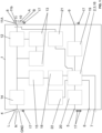
- the at least one Ethernet interface 5, the at least one USB interface 6, 7, the at least one bus interface 8 and the at least one wireless radio interface 9 are operatively connected to the electronic circuit 2.
- the electronic circuit with the processor 3 is configured in such a way that data can be exchanged between the named interfaces 5, 6, 7, 8, 9 via the processor 3 and/or that data can be exchanged between the named interfaces 5, 6, 7, 8, 9 and the processor 3 of the electronic circuit 2 are interchangeable.
- the power supply interface 4, the at least one Ethernet interface 5, the at least one USB interface 6, 7, the at least one bus interface 8 are each designed as physical sockets into which a cable with a plug can be plugged in.
- the power supply interface 4 is designed to receive mains voltage, with the mains voltage preferably being 230 volts alternating current.
- the energy supply interface 4 here comprises three conductors, namely a phase conductor L, a neutral conductor N and a ground conductor GND.
- the converter 14 Downstream of the energy supply interface 4 is a converter 14.
- the converter 14 converts the mains voltage into a lower voltage and direct current.
- the lower voltage is preferably in the range of 18 to 24 volts.
- the bus interface also has a power supply interface 11 in addition to the data interface.
- the feed interface 11 is configured in such a way that a sanitary item connected to the bus interface 8 can be supplied with electrical energy or that a sanitary item controller connected to the bus interface 8 can be supplied with electrical energy.
- the feed interface 11 is in conductive connection with the converter 14 and is accordingly fed by it.
- a load shedding switch 12 with a current measuring unit 13 is connected upstream of the feed interface 11 .
- the load shedding switch 12 is designed such that when an overcurrent is measured by the current measuring unit 13 or a short circuit is detected, the load shedding switch 12 performs a switching operation so that the supply interface 10 can be switched off at least briefly.
- the feed interface has two electrical contacts 11a and 11b to which a cable leading to the sanitary article can be connected.
- the converter 14 also feeds the electronic circuit 2 with the processor 3.
- a voltage converter 15 and a DC voltage regulator 18 are arranged between the converter 14 and the electronic circuit 2.
- the reduced voltage after the voltage converter is preferably in the range from 1.5 to 12 volts.
- the DC voltage regulator 18 a constant voltage can be provided for the processor.
- the at least one bus interface 5 is preferably connected to a sanitary article control of at least one sanitary article by a cable.
- a number of sanitary articles are preferably connected to the bus interface 5 with their respective sanitary article controls.
- Data such as control data and/or status data can be exchanged between the bus interface 5 and the processor 3 via this connection.
- the at least one Ethernet interface 5, the at least one USB interface 6, 7, the at least one bus interface 8 and the at least one wireless radio interface 9 are connected to the processor 3 of the electronic circuit 2 via data connections. Data can be exchanged between the interfaces 5, 6, 7, 8 and 9 and the processor 3 via these data connections.
- the electronic circuit 2 preferably also has a memory 16 which is designed to store the data.
- the memory 16 is operatively connected via the processor 3 to the interfaces 5, 6, 7, 8 and 9 in such a way that data can be exchanged between the interfaces 5, 6, 7, 8 and 9 and the processor 3.
- the bus interface 8 has a data interface 10, which is preferably an RS-485 interface.
- the data interface 10 is configured in such a way that data can be exchanged between a sanitary article control of a sanitary article connected to the bus interface 8 and the RS-485 interface.
- the RS-485 interface has two conductors A and B.
- a driver module 21 is assigned to the RS-485 interface here.
- a USB interface 6 of said USB interfaces is designed to accommodate a data carrier, the USB interface 6 and the processor 3 of the electronic circuit 2 are configured such that via the USB interface 6 data between the processor 3 and the data carrier are interchangeable.
- the other of the two USB interfaces 7 of said USB interfaces is designed to accommodate an adapter with an extension interface, the USB interface 7 and the processor 3 of the electronic circuit 2 being configured such that the USB interface 7 data are interchangeable between the processor 3 and the expansion interface of the adapter.
- the wireless radio interface 9 is a WIFI interface and/or a Bluetooth interface.
- a corresponding WIFI Bluetooth module 19 is arranged for this purpose.
- An Ethernet module 20 is also assigned to the Ethernet interface 5 .
- the gateway 1 preferably also has at least one status light 17, which is configured in such a way that a status can be displayed to a user.
- one status light 17 is arranged for each interface 4, 5, 6, 7, 8 and 9.
- the gateway 1 is used in a sanitary system, the gateway 1 being operatively connected via the bus interface to at least one sanitary article controller of at least one sanitary article.
- the gateway can have a "trusted platform module" in which security elements are stored.
- the corresponding module bears the reference number 22.
Landscapes
- Engineering & Computer Science (AREA)
- Automation & Control Theory (AREA)
- Physics & Mathematics (AREA)
- General Physics & Mathematics (AREA)
- Computing Systems (AREA)
- Computer Networks & Wireless Communication (AREA)
- Signal Processing (AREA)
- Selective Calling Equipment (AREA)
Priority Applications (1)
| Application Number | Priority Date | Filing Date | Title |
|---|---|---|---|
| EP21206550.2A EP4178165A1 (fr) | 2021-11-04 | 2021-11-04 | Passerelle pour un système sanitaire |
Applications Claiming Priority (1)
| Application Number | Priority Date | Filing Date | Title |
|---|---|---|---|
| EP21206550.2A EP4178165A1 (fr) | 2021-11-04 | 2021-11-04 | Passerelle pour un système sanitaire |
Publications (1)
| Publication Number | Publication Date |
|---|---|
| EP4178165A1 true EP4178165A1 (fr) | 2023-05-10 |
Family
ID=78528763
Family Applications (1)
| Application Number | Title | Priority Date | Filing Date |
|---|---|---|---|
| EP21206550.2A Pending EP4178165A1 (fr) | 2021-11-04 | 2021-11-04 | Passerelle pour un système sanitaire |
Country Status (1)
| Country | Link |
|---|---|
| EP (1) | EP4178165A1 (fr) |
Citations (6)
| Publication number | Priority date | Publication date | Assignee | Title |
|---|---|---|---|---|
| DE9313983U1 (de) | 1993-09-15 | 1993-11-25 | Aqua Butzke-Werke AG, 10969 Berlin | Konfiguration zur komplexen Steuerung sanitärer Anlagen |
| EP1309760B1 (fr) * | 2000-08-17 | 2005-03-23 | AQUA Rotter GmbH | Systeme de commande et de surveillance de robinetterie sanitaire |
| WO2009061857A2 (fr) | 2007-11-05 | 2009-05-14 | Sloan Valve Company | Supérette de toilettes publiques |
| US20150194039A1 (en) * | 2014-01-03 | 2015-07-09 | Intwine Energy | Connected gateway |
| EP3343314A1 (fr) * | 2017-01-02 | 2018-07-04 | Verisure Sàrl | Procédé et dispositif de gestion des coupures d'alimentation dans des systèmes domestiques sans fil |
| CN212541067U (zh) * | 2020-07-22 | 2021-02-12 | 武汉万象奥科电子有限公司 | 一种基于sam9x60的物联网人机界面系统 |
-
2021
- 2021-11-04 EP EP21206550.2A patent/EP4178165A1/fr active Pending
Patent Citations (6)
| Publication number | Priority date | Publication date | Assignee | Title |
|---|---|---|---|---|
| DE9313983U1 (de) | 1993-09-15 | 1993-11-25 | Aqua Butzke-Werke AG, 10969 Berlin | Konfiguration zur komplexen Steuerung sanitärer Anlagen |
| EP1309760B1 (fr) * | 2000-08-17 | 2005-03-23 | AQUA Rotter GmbH | Systeme de commande et de surveillance de robinetterie sanitaire |
| WO2009061857A2 (fr) | 2007-11-05 | 2009-05-14 | Sloan Valve Company | Supérette de toilettes publiques |
| US20150194039A1 (en) * | 2014-01-03 | 2015-07-09 | Intwine Energy | Connected gateway |
| EP3343314A1 (fr) * | 2017-01-02 | 2018-07-04 | Verisure Sàrl | Procédé et dispositif de gestion des coupures d'alimentation dans des systèmes domestiques sans fil |
| CN212541067U (zh) * | 2020-07-22 | 2021-02-12 | 武汉万象奥科电子有限公司 | 一种基于sam9x60的物联网人机界面系统 |
Similar Documents
| Publication | Publication Date | Title |
|---|---|---|
| EP1258957B1 (fr) | Ensemble d'interrupteurs | |
| DE112013001642T5 (de) | Stromverbrauchsüberwachung von Strom-Einspeisungs-Kreisen unter Verwendung von Stromverteilungs-Einheiten | |
| DE102019211222B4 (de) | Programmierbares Multisensor-Mess- und Steuerungssystem zum Adressieren von Erweiterungsmodulen | |
| EP3700066B1 (fr) | Installation de transport permettant de transporter des marchandises de détail pourvue de système de raccordement électrique amélioré | |
| DE102009043455A1 (de) | Anordnung zum Installieren von Geräten der Gebäudesystemtechnik | |
| WO2009100762A1 (fr) | Appareil de commande d’éclairage | |
| EP3186862B1 (fr) | Module d'automatisation pour la domotique | |
| EP2258153B1 (fr) | Système modulaire électrique comprenant un module de bus de terrain à utilisation variable | |
| EP2424075B1 (fr) | Participants pour un système d'installation de bâtiment et système d'installation de bâtiment doté de tels participants | |
| EP4178165A1 (fr) | Passerelle pour un système sanitaire | |
| DE102004007260B4 (de) | Elektrifiziereinrichtung für einen Schaltschrank oder ein Rack | |
| EP3180822A1 (fr) | Prise électrique multiple et système de table à positionnement électrique | |
| DE202013012791U1 (de) | Anordnung zum Installieren von Geräten der Gebäudesystemtechnik | |
| EP2960664A1 (fr) | Module, unité de fonctionnement et système d'enregistrement de puissances et de quantités d'énergie dans des conducteurs | |
| EP2658180A1 (fr) | Système modulaire d'appareils d'installation électriques encastrés | |
| EP1993010B1 (fr) | Unité de détection | |
| WO2009030243A1 (fr) | Module de base ou d'extension pour appareil de commutation modulaire, appareil de commutation modulaire et dispositif concevoir ou pour configurer un appareil de commutation modulaire | |
| DE102007063590A1 (de) | Elektrisches Installationsgerät | |
| WO2008154755A2 (fr) | Gestion de puissance | |
| DE102007022906B3 (de) | Vorrichtung zur elektrischen Energieversorgung von mehreren Geräten und Verfahren zum Betreiben | |
| EP2073321B1 (fr) | Appareil d'installation | |
| EP4177409B1 (fr) | Système sanitaire | |
| DE102019202921B4 (de) | Lichtverteilervorrichtung für eine Fertigungsinfrastruktur, Verfahren zum Bestücken einer Lichtverteilervorrichtung | |
| DE102012103252A1 (de) | Steuervorrichtung für Niederspannungs-Schaltanlagen | |
| DE202014000549U1 (de) | Netzwerkzugangsvorrichtung |
Legal Events
| Date | Code | Title | Description |
|---|---|---|---|
| PUAI | Public reference made under article 153(3) epc to a published international application that has entered the european phase |
Free format text: ORIGINAL CODE: 0009012 |
|
| STAA | Information on the status of an ep patent application or granted ep patent |
Free format text: STATUS: THE APPLICATION HAS BEEN PUBLISHED |
|
| AK | Designated contracting states |
Kind code of ref document: A1 Designated state(s): AL AT BE BG CH CY CZ DE DK EE ES FI FR GB GR HR HU IE IS IT LI LT LU LV MC MK MT NL NO PL PT RO RS SE SI SK SM TR |
|
| STAA | Information on the status of an ep patent application or granted ep patent |
Free format text: STATUS: REQUEST FOR EXAMINATION WAS MADE |
|
| 17P | Request for examination filed |
Effective date: 20231025 |
|
| RBV | Designated contracting states (corrected) |
Designated state(s): AL AT BE BG CH CY CZ DE DK EE ES FI FR GB GR HR HU IE IS IT LI LT LU LV MC MK MT NL NO PL PT RO RS SE SI SK SM TR |
|
| RAP1 | Party data changed (applicant data changed or rights of an application transferred) |
Owner name: GEBERIT INTERNATIONAL AG |
|
| STAA | Information on the status of an ep patent application or granted ep patent |
Free format text: STATUS: EXAMINATION IS IN PROGRESS |
|
| 17Q | First examination report despatched |
Effective date: 20250723 |