EP4178699B1 - Rail à treillis et ensemble de montagnes russes équipé de celui-ci - Google Patents
Rail à treillis et ensemble de montagnes russes équipé de celui-ci Download PDFInfo
- Publication number
- EP4178699B1 EP4178699B1 EP21732867.3A EP21732867A EP4178699B1 EP 4178699 B1 EP4178699 B1 EP 4178699B1 EP 21732867 A EP21732867 A EP 21732867A EP 4178699 B1 EP4178699 B1 EP 4178699B1
- Authority
- EP
- European Patent Office
- Prior art keywords
- rail
- profiles
- truss
- tube
- vertical
- Prior art date
- Legal status (The legal status is an assumption and is not a legal conclusion. Google has not performed a legal analysis and makes no representation as to the accuracy of the status listed.)
- Active
Links
Images


Classifications
-
- A—HUMAN NECESSITIES
- A63—SPORTS; GAMES; AMUSEMENTS
- A63G—MERRY-GO-ROUNDS; SWINGS; ROCKING-HORSES; CHUTES; SWITCHBACKS; SIMILAR DEVICES FOR PUBLIC AMUSEMENT
- A63G7/00—Up-and-down hill tracks; Switchbacks
Definitions
- the present invention relates to a lattice rail for a roller coaster or similar ride, with two rail tubes that can be directly driven on by a carriage arrangement and a non-driven belt tube, and vertical lattice profiles that connect the rail tubes and the belt tube to one another in a stiffening manner and which comprise vertical diagonal profiles that run diagonally between the belt tube and the respective rail tube, alternating between rising and falling.
- the invention relates to a roller coaster arrangement, comprising a carriage arrangement and at least one lattice rail of the aforementioned type.
- Such rails and arrangements are known from the state of the art.
- These rail systems include, for example, rails made of wood or steel, with one or more rail profiles of any shape, whereby the load-bearing capacity of the rail or the individual rail profiles, also referred to below as rail tubes, can be improved by stiffening them using lattice profiles.
- the present invention relates to a common embodiment of a rail, which is designed as such a lattice rail and usually consists of two rail tubes that can be driven on directly and a third, non-driven belt tube.
- the rail tubes and the belt tubes are usually designed with the same diameter and, moreover, are usually designed as tubes or similar round profiles.
- lattice profiles are used that run between the individual tubes and stiffen them. In this context, it is relevant that the lattice profiles are arranged in such a way that they do not hinder the free movement of the wheels or other parts of the train along the rail and in particular the rail tubes.
- lattice profiles include vertical lattice profiles with vertical diagonal profiles and post profiles, as well as horizontal lattice profiles with horizontal diagonal profiles and cross profiles.
- the infill on such truss rails has the posts and/or cross-sections in the normal section of the rail, i.e. in the bulkhead plane, and the vertical diagonal profiles and horizontal diagonal profiles in the fields between these "bulkheads".
- 3-belt truss rails there are also 4-belt truss rails with two directly accessible Rail tubes and two non-driveable belt tubes, which are also connected to one another in a stiffening manner via lattice profiles, the statics and driving dynamics of which are not comparable to a 3-belt lattice rail.
- the invention is directed to a 3-belt lattice rail, in particular to a lattice rail consisting of two directly driveable rail tubes and a third, single or only non-driveable belt tube, i.e. to a lattice rail with a total of three rail tubes.
- a right and a left rail tube are connected by means of cross profiles for reinforcement.
- a belt tube is coupled to the rail tubes via post profiles, with the post profiles connecting to the above-mentioned cross profiles.
- vertical diagonal profiles run diagonally between the individual post profiles.
- Horizontal diagonal profiles run in the rail plane between the individual cross profiles.
- a further disadvantage of these designs is the large number of welded joints overall as well as the large number of vertical truss profiles, such as post profiles, in detail.
- the object of the present invention is therefore to provide an improved truss rail which can be manufactured with a comparable global load-bearing behavior, a low welding volume and reduced material expenditure as well as an improved joint situation.
- this object is achieved by a lattice rail for a ride, with two rail tubes that can be directly driven on with a carriage arrangement, a non-driven belt tube, and vertical lattice profiles that connect the rail tubes and the belt tube to one another in a stiffening manner and comprise the vertical diagonal profiles that run diagonally between the belt tube and the respective rail tube, alternating between rising and falling, wherein in at least one connection area or lattice node of the vertical diagonal profiles on the belt tube, no further vertical lattice profile and in particular no post profile is connected to it.
- roller coaster arrangement comprising a carriage arrangement and at least one lattice rail according to the type mentioned above and described in more detail below.
- a steel lattice rail is understood to mean any lattice rail that is made of a metallic material or similar statically effective material.
- the invention is not intended to be limited to steel lattice rails; the use of materials that have similar material properties to steel is also conceivable, such as aluminum, fiber composites based on carbon fibers, glass fibers, nylon fibers, ceramic fibers, aramid fibers, or natural fibers. Wood composites are also conceivable for use in lattice rails.
- a lattice rail is understood to mean a rail whose rail tubes and belt tubes are connected by means of lattice profiles, such as the vertical lattice profiles described above.
- lattice profiles are preferably mainly loaded as normal bars.
- rail tube or tube is understood to mean any type of tube with a cross-sectional geometry that is suitable for load transfer. This preferably refers to closed-walled beams and above all tubes with a circular cross-section.
- tube in the scope of the invention. This includes rectangular profiles, box profiles or similar closed profiles, but also open profiles such as T-profiles, I-profiles, multi-layer or multi-element profiles, etc.
- no further vertical truss profile is connected to it in at least one connection area of the vertical diagonal profiles on the chord tube.
- At least one means in particular that at least one connection area of the truss rail must meet this condition.
- post profiles are dispensed with in at least one connection area.
- the number of connections in at least one connection area on the chord tube is reduced. This reduces, for example, the welding volume, which is proportional to the square of the wall thickness of the welded profiles.
- the material costs are reduced because additional vertical lattice profiles such as post profiles are dispensed with. The result is therefore reduced material costs and a reduced overall weight of the rail.
- connection area in the at least one connection area, preferably only four vertical diagonal profiles are connected to the chord tube as vertical lattice profiles.
- a ratio of pipe diameter (D) to wall thickness (thickness t), hereinafter referred to as D/t ratio, can be greater than 6, or greater than 7, or greater than 8, or greater than 9, or greater than 10, or greater than 11, or greater than 12 in the structure according to the invention with in particular only four vertical lattice profiles which open into a connection area.
- the connecting seams of the vertical diagonal profiles connected to the belt tube can have a minimum distance from each other, which is always smaller than the diameter of the vertical diagonal profiles in the connection area. This can reduce the occurrence of additional bending moments at the connecting seams when a load is taken up, thus enabling improved load-bearing and bending behavior of the undercarriage rail.
- the truss rail can be made of steel and the connecting seam can be a weld.
- a field section of the lattice rail in all connection areas of the vertical diagonal profiles on the chord tube, no further vertical lattice profile, in particular a post profile, is connected to it.
- the field section can have two connection areas on the chord tube.
- post profiles can be provided which run essentially orthogonally between the chord tube and the respective rail tube and are connected directly to the chord tube and the rail tube.
- Orthogonal means in particular in the scope of the invention that the post profiles on at least one tube of the lattice rail, viewed in the side view of the lattice rail, are essentially are connected vertically.
- Orthogonal preferably also means that the post profiles are essentially guided in the bulkhead plane of the truss rail.
- the post profiles can reduce the span of the rail tubes.
- the post profiles can improve load transfer from the rail tubes to the support pillars in the support section.
- no vertical truss profile and in particular no post profile can be connected to the respective rail tube.
- the post profile By omitting the post profile at a joint, the occurrence of transverse forces, bending moments and torsional forces can be reduced, since the joint is no longer located at a truss node. This makes it possible to further improve the joint situation.
- no further vertical lattice profile or in particular a post profile is connected to the respective rail tube in at least one connection area of the vertical diagonal profiles.
- a post profile is therefore dispensed with, which further reduces the material and welding costs and also improves the overall impression of the lattice rail.
- the rail tubes are connected to each other via horizontal lattice profiles for stiffening.
- the horizontal lattice profiles include cross profiles that run essentially orthogonally between the rail tubes, with the cross profiles being connected directly to the rail tubes.
- the cross profiles preferably run into the rail tubes in the area of the connection points of the vertical diagonal profiles.
- the vertical diagonal profiles can therefore be connected directly to a cross profile in the connection area to the respective rail tube.
- the horizontal lattice profiles may preferably further comprise horizontal diagonal profiles which run diagonally between the rail tubes and which are directly connected to at least one transverse profile, preferably two transverse profiles, near the rail tubes.
- the vertical lattice profiles are connected to the rail tubes or coupled to them, for example via the cross profiles, in such a way that a chassis clearance is formed on the top, bottom and outside of the rail tube for a chassis of the carriage arrangement.
- the top is defined here as the space above a plane formed by the rail tubes that points away from the chord tube.
- an influence can be exerted on the chassis clearance when vertical diagonal profiles are connected directly to the rail tubes.
- the invention also relates to a roller coaster arrangement comprising a carriage arrangement and at least one lattice rail according to the type mentioned above and described in more detail below.
- the carriage arrangement preferably has at least one chassis which surrounds at least one rail tube of the steel lattice rail on the top, bottom and outside. All of the embodiments, special features and advantages of the steel lattice rail according to the invention mentioned here can be transferred to such a roller coaster arrangement and vice versa.
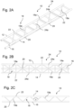
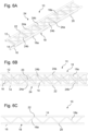
- a steel lattice rail 100 known from the prior art is shown in isometric view and side view.
- This steel lattice rail 100 has vertical post profiles 118b in connection areas 120 of vertical diagonal profiles 118a on a chord tube 116.
- a prevailing assumption in the prior art is that these vertical post profiles 118b are statically necessary at least in the connection area 120 on the chord tube 116.
- a steel lattice rail 100' according to the invention which dispenses with these post profiles 118b, as in Fig.9 illustrated, and as described with reference to the following embodiments of the truss rail 10 according to the invention, several advantages in terms of manufacturing costs, material costs, or material weights.
- connection area 120 the connection area 120
- the omission of the post profiles shown the possibility of attaching the vertical diagonal profiles 118a in the connection area 120 to the chord tube 116 with a small distance from each other on the chord tube 116, so that the four vertical diagonal profiles 118a can converge almost point-like in the connection area 120, as in Fig. 2C and Fig.3 in the further truss rail 10 according to the invention in the connection area 20.
- a roller coaster arrangement 30 or a similar ride is shown, which comprises at least one truss rail 10 according to the invention, which with reference to Fig. 2 to Fig. 7 will be described in detail later.
- a carriage arrangement 32 can have a chassis 33 with running wheels, which surrounds at least one rail tube of the framework 10 on the top, bottom and outside.
- the chassis is in Fig.1 shown schematically and can have different designs.
- the chassis rail 10 is stabilized by support pillars 34.
- the roller coaster arrangement 30 is usually made of a material that enables a high level of operational reliability in order to ensure that passengers can ride safely.
- Steel, for example, can be an advantageous material for the roller coaster arrangement 30, but wood can also be used.
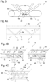
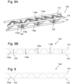
- Fig. 2A shows an isometric view of an embodiment of the lattice rail 10.
- the lattice rail 10 comprises two rail tubes 12, 14 that can be directly driven over with the carriage arrangement 32 and a non-driven belt tube 16.
- the lattice rail 10 has vertical lattice profiles 18 that connect the rail tubes 12, 14 and the belt tube 16 to one another in a stiffening manner.
- the vertical lattice profiles 18 are connected to the rail tubes 12, 14 in such a way that a chassis clearance for the chassis 33 of the carriage arrangement 32 is formed on the top, bottom and outside of the rail tube 12, 14.
- the vertical lattice profiles 18 comprise vertical diagonal profiles 18a that run diagonally between the belt tube 16 and the respective rail tube 12, 14, alternating between rising and falling.
- An angle ⁇ between the vertical diagonal profiles 18a can be in a range of 30° to 60°, preferably 45° or lower. In this way, loads introduced into the rail tubes 12, 14 are safely introduced into the chord tube 16 by activating the vertical diagonal profiles 18a.
- connection area 20 of the vertical diagonal profiles 18a on the chord tube 16 no further vertical lattice profile 18 is connected thereto.
- further vertical lattice profiles 18, such as vertical post profiles 18b ( Fig. 4B ) which is particularly evident in the Fig. 2C
- the welded joints in the connection area 20 on the chord tube 16 are reduced and material costs are saved.
- the lattice rail 10 is not limited to the above embodiment.
- a further embodiment of the lattice rail 10 for a ride with two rail tubes 12, 14 that can be directly driven on by a carriage arrangement, a non-driven belt tube 16, and vertical lattice profiles 18 that connect the rail tubes 12, 14 and the belt tube 16 to one another in a stiffening manner and comprise the vertical diagonal profiles 18a that run diagonally between the belt tube 16 and the respective rail tube 12, 14, alternately rising and falling, can be provided according to the invention in a No vertical truss profile 18 may be connected to the joint section SA of the truss rail.
- Fig. 2B shown top view of the truss rail 10.
- the vertical diagonal profiles 18a can be connected directly to the chord tube 16 and to the rail tube 12, 14.
- no further vertical lattice profile 18 can be connected to it.
- no post profile 18b (as in Fig. 4B shown) which runs essentially orthogonally between the chord tube 16 and the respective rail tube 12, 14.
- only two vertical diagonal profiles 18a are connected as vertical lattice profiles 18 to a respective rail tube 12, 14.
- the direct connection to the rail tubes 12, 14 enables load transfer by the vertical diagonal profiles 18a without additional post profiles 18b.
- the lattice rail 10 can therefore have sections without post profiles 18b in the connection areas 20 on the chord tube 16 and in the connection areas 22 on the rail tubes 12, 14.
- the rail tubes 12, 14 can be connected to one another in a stiffening manner via horizontal lattice profiles 24.
- the horizontal lattice profiles 24 comprise cross profiles 24a which run essentially orthogonally between the rail tubes 12, 14, as in Fig. 2A illustrated.
- the cross profiles 24a are preferably connected directly to the rail tubes 12, 14.
- the rail tube profiles 12, 14, the vertical diagonal profiles 18a, the belt tube 16 and the cross profiles 24a are designed as round profiles. It is of course also possible to choose other cross-sectional shapes, although the round cross-section is preferable to a square cross-section.
- a pipe diameter of the respective profiles can be in a range of 130 to 190 mm, or in a range of 110 to 170 mm.
- the wall thickness of the profiles can be in a range of 12 to 25 mm.
- a ratio of pipe diameter D to wall thickness t (D/t ratio) is usually in a range of 5 to 20.
- D/t ratio is 7.
- the D/t ratio is approximately 17.
- the rule here is that the wall thickness can decrease as the pipe diameter increases, i.e.
- the larger the pipe diameter the larger the D/t ratio can be.
- An advantage of the roller coaster arrangement 30 according to the invention and the lattice rail 10 is that more space is created in the lattice junction due to the reduced number of connected lattice profiles and thus the lattice profiles can be designed with a larger diameter and a smaller wall thickness. This saves weight and further reduces the amount of welding required.
- the D/t ratio may be greater than 6, or greater than 7, or greater than 8, or greater than 9, or greater than 10, or greater than 11, or greater than 12.
- Fig.3 a detailed view of the truss rail 10, in particular of the connection area 20 on the chord tube 16, is shown.
- connecting seams which are illustrated by the hatched areas, can have a respective minimum distance d from each other, which is always less than three times, twice or once the diameter of the vertical diagonal profiles 18a in the connection area 20.
- an eccentricity of the vertical diagonal profiles 18a on the chord tube 16 can be kept low in relation to a line of action of a force acting through load bearing. This can reduce the occurrence of additional bending moments at the connecting seams and thus increase the load-bearing capacity of the truss rail 10.
- this line of action can, for example, refer to the center of the minimum distance d between the connecting seams.
- a span or support width of the truss rail 10, in which the truss rail 10 must withstand a load applied by a carriage arrangement 32 can be increased.
- the occurrence of secondary bending moments at the connecting seams can be prevented by a low eccentricity, ie by the minimal distance between the attached truss profiles in a truss node, at least partially compensated.
- the reduced local load-bearing behavior resulting from the elimination of the post profiles 18b is at least partially compensated due to the increased stiffening by the vertical diagonal profiles 18a connected to the chord tube 16 with a minimal distance d from each other.
- This stiffening is made easier according to the invention in that, due to the reduced number of connected truss profiles in the truss node, more space is available for the connection of the four truss diagonal profiles in particular and these can therefore be designed with a larger diameter and a larger D/t ratio.
- the connecting seams of the vertical diagonal profiles 18a connected to the belt tube 16 or the peripheral outer edge region of the vertical diagonal profiles 18a in the connection region 20 can have a respective minimum distance d which is always less than three times, twice or once the maximum diameter of the vertical diagonal profiles 18a in the connection region 20 and which is in particular less than 90%, or less than 80%, or less than 70%, or less than 60%, or less than 50%, or less than 40% of the maximum diameter of the vertical diagonal profiles 18a.
- the minimum distance d can be less than 500 mm, or less than 400 mm, or less than 300 mm, or less than 200 mm, or less than 150 mm, or less than 100 mm, or less than 50 mm.
- the mutual distance between the pipe centers in the connection area 20 of the four vertical diagonal profiles 18a in particular can always be less than 800 mm, or less than 700 mm, or less than 600 mm, or less than 500 mm, or less than 400 mm, or less than 300 mm, or less than 200 mm.
- the mutual distance between the pipe centers in the connection area 20 of the four vertical diagonal profiles 18a in particular can always be less than four times, or less than 3.5 times, or less than three times, or less than 2.5 times, or less than twice, or less than 1.5 times, or less than once the maximum diameter of the vertical diagonal profiles 18a.
- the truss rail 10 can be made of steel and the connecting seam can be a weld seam.
- other connecting seams are also conceivable, such as an adhesive bead or adhesive track in the case of a non-metallic composite or fiber composite.
- a field section FA of the truss rail 10 in all Connection areas 20 of the vertical diagonal profiles 18a on the belt tube 16 no further vertical truss profile 18 is connected to it.
- the field section FA here refers to a self-supporting section in which no supporting pillars or similar supports support a rail section of the truss rail 10.
- the field section FA also does not contain any rail connection area or butt ends of the truss rail.
- the field section FA therefore refers to a section of the truss rail 10 of the roller coaster arrangement 30 that does not have a support section AA and no butt section SA, which are described in detail below.
- Fig. 4A shown, with the field area FA being illustrated by an arrow.
- the field area FA comprises two connection areas 20 on the belt tube 16 in which no post profiles 18b are connected to the belt tube 16.
- connection areas 20 on the belt tube 16 in the entire lattice rail track of the roller coaster arrangement 30 may have no further vertical lattice profile 18 and in particular no post profile 18b.
- a schematic view of the truss rail 10 is shown, which represents a support section AA of the truss rail 10 in the connection area 20 of the vertical diagonal profiles 18a on the chord tube 16 or on the respective rail tube 12, 14.
- the truss rail 10 is shown in the Fig. 4B and 4C shown in a highly simplified manner, whereby the vertical diagonal profiles 18a connected to the rail tube 12 have been omitted for reasons of clarity.
- post profiles 18b are provided, which run essentially orthogonally between the chord tube 16 and the respective rail tube 12, 14 and are connected directly to the chord tube 16 and the rail tube 12, 14.
- the post profiles 18b can be connected to the respective rail tube 12, 14 at the connection area 22 of the vertical diagonal profiles 18a. However, the post profiles 18b can also be connected to the connection area 20 of the vertical diagonal profiles 18a at the belt tube 16, which can be seen in the right detailed view in Fig. 4B
- the post profiles 18b are supported by the support pillars 34 ( Fig.1 ) and supported by a floor surface (not shown).
- no further vertical lattice profile 18 and in particular no post profile 18b may be connected to it.
- the extent of the support section AA in the rail direction of the lattice rail 10 corresponds at least to the width of the supporting support or pillar 34.
- the support section AA can also extend symmetrically to the support point of the pillar 34 on both sides of the pillar 34 by 100 mm, 200 mm, 300 mm, 400 mm or 500 mm along the lattice rail 10 away from the support point.
- the crucial point is that the support section AA covers a rail area of the lattice rail 10 which is directly adjacent to the support or pillar 34.
- a joint section SA described below can also coincide with a support section AA.
- a span section FA does not contain a splice section SA or a support section AA.
- Fig. 4C is an isometric detailed view of the lattice rail 10, which illustrates the joint section SA of the lattice rail 10.
- the joint section SA is shown in this example by a circle.
- the joint section SA of the lattice rail 10 is to be interpreted as an area of the lattice rail 10 that is immediately adjacent to a joint end SE and extends in particular by a distance a away from the joint end SE.
- the distance a can be ten times, five times, three times or twice the maximum diameter of the rail tube 12, 14.
- the distance a can be equal to 500 mm, 1000 mm or 1500 mm. It is pointed out that the in Fig. 2A to Fig. 9 with the exception of Fig.
- a chassis clearance can be formed, which enables optimal accommodation of the chassis 33.
- a transverse profile 24a is also shown which is spaced from the joint section SA.
- the transverse profile 24a can also be arranged at the joint section SA.
- the connection area 20 of the vertical diagonal profiles 10 to the chord tube 16 can be located in the joint section SA, in which case no further vertical lattice profile 18 and in particular no post profile 18b is connected to the connection area 20 of the two vertical diagonal profiles 18a on the chord tube 16.
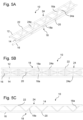
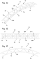
- Fig. 5A to Fig. 5C show an embodiment of the lattice rail 10 with vertical diagonal profiles 18a, which are directly connected to the cross profiles 24a. Due to the direct connection to the cross profiles 24a, a small eccentricity can be realized on the respective rail tube 12, 14, whereby additional bending and torques at the connection areas 22 are reduced. This is particularly advantageous if the lattice rail 10 has a curved shape, as in Fig. 5D to Fig. 5F illustrated.
- the truss rail 10 is shown with horizontal diagonal profiles 24b, which run diagonally between the rail tubes 12, 14 and which are connected directly to at least one cross profile 24a, preferably two cross profiles 24a, near the rail tubes 12, 14.
- the vertical diagonal profiles 18a are connected directly to the respective rail tube 12, 14.
- the horizontal diagonal profiles 24b can be used to additionally stabilize the truss rail 10 with regard to horizontal loads and torsional loads.
- the direct connection of the vertical diagonal profiles 18a to the respective rail tube 12, 14 and belt tube 16 means that further post profiles 18b can be dispensed with. This reduces the increase in wall thickness, since no intermediate step via post profiles 18b or cross profiles 24a has to be carried out and, as described above, the vertical lattice profiles can be designed with a larger diameter and smaller wall thickness.
- a preferred embodiment of the lattice rail 10 is shown with horizontal diagonal profiles 24b, which are connected to the respective rail tubes 12, 14, and which has vertical diagonal profiles 18a, which are connected to the cross profiles 24a.
- a small eccentricity can be achieved on the respective rail tube 12, 14 by directly connecting the vertical diagonal profiles 18a to the cross profiles 24a. Locally occurring bending moments can thus be further reduced.
- the resulting reduction of local secondary stresses can enable an improved global load-bearing behavior.
- a locally vertical load direction is understood to mean the vertical load into or out of the seat in the local vehicle reference system of the carriage arrangement 32.
- This load direction represents the main load direction in the roller coaster arrangement 30 in the sense of the invention. This means that the largest load components are to be expected in this direction.
- the invention relates to a roller coaster arrangement 30 in which the locally vertical load direction is essentially perpendicular to a straight line in the bulkhead plane through the left and right rail tubes 12, 14.
- the belt tube 16 is therefore located between the two rail tubes 12, 14 in the local vertical direction or main load direction.
- a lattice rail 10 designed as a three-belt rail is provided for a ride which has only two rail tubes 12, 14 that can be directly driven over by a carriage arrangement 32 and only one non-driven belt tube 16, wherein the local vertical load or main load exerted on the lattice rail 10 by the carriage arrangement 32 driving over the rail tubes 12, 14 always has a direction that is substantially perpendicular or perpendicular to the rail plane and/or substantially parallel or parallel to the bulkhead plane of the rail tubes 12, 14.
- the belt tube 16 is always located below or behind (in the case of load direction into the seat) the rail plane of the rail tubes 12, 14.
- the belt tube 16 is always located below or behind (in the case of load direction into the seat) both the one and the other rail tube 12, 14. Furthermore, in the local vertical load direction or main load direction, the belt tube 16 is always located below or behind (in the case of load direction into the seat) and between both rail tubes 12, 14.
- a roller coaster arrangement 30 which has a carriage arrangement 32 and at least one truss rail 10, wherein the at least one truss rail 10 has the above-described rail tube-belt tube arrangement corresponding to the locally vertical load direction.
Landscapes
- Rod-Shaped Construction Members (AREA)
Claims (16)
- Rail à treillis (10) pour un manège, avec- avec deux tubes de rail (12, 14), pouvant être parcourus directement par un ensemble de chariots,- un tube de ceinture ne pouvant pas être parcouru (16), et- des profilés à treillis verticaux (18) qui relient entre eux les tubes de rail (12, 14) et le le tube de ceinture (16) en les rigidifiant et qui comprennent les profilés diagonaux verticaux (18a) qui s'étendent en diagonale entre le tube de ceinture (16) et le tube de rail (12, 14) respectif en montant et en descendant en alternance, caractérisé en ce que dans au moins une zone de raccordement (20) des profilés diagonaux verticaux (18a) sur le tube de ceinture (16), aucun autre profilé de treillis vertical (18) n'y est raccordé.
- Rail à treillis (10) selon la revendication 1, caractérisé en ce que dans l'au moins une zone de raccordement (20), seuls quatre profilés diagonaux verticaux (18a) sont raccordés au tube de ceinture (16) en tant que profilés de treillis verticaux (18).
- Rail à treillis (10) selon la revendication 1 ou 2, caractérisé en ce que dans au moins une zone de raccordement (20), les joints de liaison des profilés diagonaux verticaux (18a) reliés au tube de ceinture (16) présentent entre eux une distance minimale respective (d) qui est toujours inférieure au triple du diamètre des profilés diagonaux verticaux (18a) dans la zone de raccordement (20).
- Rail à treillis (10) selon l'une des revendications précédentes, caractérisé en ce que, dans une section de travée (FA) du rail à treillis (10), dans toutes les zones de raccordement (20) des profilés diagonaux verticaux (18a) au niveau du tube de ceinture (16), respectivement aucun autre profilé de treillis vertical (18) n'est raccordé à celui-ci.
- Rail à treillis (10) selon l'une des revendications précédentes, caractérisé en ce que dans une section d'appui (AA) du rail à treillis (10), dans la zone de raccordement (20) des profilés diagonaux verticaux (18a) au niveau du tube de ceinture (16) ou au niveau du tube de rail respectif (12, 14), il est prévu des profilés de montant (18b) qui s'étendent sensiblement orthogonalement entre le tube de ceinture (16) et le tube de rail respectif (12, 14) et qui sont raccordés directement au tube de ceinture (16) et au tube de rail (12, 14).
- Rail à treillis (10) selon l'une quelconque des revendications précédentes, caractérisé en ce que, dans une section de joint (SA) du rail à treillis (10) au niveau du tube de rail respectif (12, 14), aucun profilé de treillis vertical (18) n'est raccordé à celui-ci.
- Rail à treillis (10) selon l'une des revendications précédentes, caractérisé en ce que les profilés diagonaux verticaux (18a) sont raccordés directement au tube de ceinture (16) et directement au tube de rail (12, 14).
- Rail à treillis (10) selon l'une des revendications précédentes, caractérisé en ce que dans au moins une zone de raccordement (22) des profilés diagonaux verticaux (18a) au niveau du tube de rail respectif (12, 14), aucun autre profilé de treillis vertical (18,) n'est raccordé à celui-ci.
- Rail à treillis (10) selon l'une des revendications précédentes, caractérisé en ce que les tubes de rail (12, 14) sont reliés entre eux par des profilés de treillis horizontaux (24) en les rigidifiant.
- Rail à treillis (10) selon la revendication 9, caractérisé en ce que les profilés de treillis horizontaux (24) comprennent des profilés
transversaux (24a) qui s'étendent de manière sensiblement orthogonale entre les tubes de rail (12, 14), les profilés transversaux (24a) étant directement raccordés aux tubes de rail (12, 14). - Rail à treillis (10) selon la revendication 10, caractérisé en ce que les profilés diagonaux verticaux (18a) sont raccordés directement à un profilé transversal (24a) dans la zone de raccordement (20) au tube de rail respectif (12, 14).
- Rail à treillis (10) selon l'une quelconque des revendications précédentes, caractérisé en ce que les profilés de treillis horizontaux (24) comprennent des profilés diagonaux horizontaux (24b) qui s'étendent en diagonale entre les tubes de rail (12, 14) et qui sont raccordés directement à au moins un profilé transversal (24a), de préférence deux profilés transversaux (24a), à proximité des tubes de rail (12, 14).
- Rail à treillis (10) selon l'une quelconque des revendications précédentes, caractérisé en ce que les profilés de treillis verticaux (18) sont, en utilisation, raccordés ou couplés aux tubes de rail (12, 14) de telle sorte que, sur le côté supérieur, sur le côté inférieur et sur le côté extérieur du tube de rail (12, 14), un espace libre de train de roulement est formé pour un train de roulement (33) de l'ensemble de chariots (32).
- Rail à treillis (10) selon l'une quelconque des revendications précédentes, caractérisé en ce que la charge verticale locale exercée sur le rail à treillis (10) par le passage de l'ensemble de chariots (32) sur les tubes de rail (12, 14) en cours d'utilisation présente toujours une direction sensiblement perpendiculaire au plan des rails des tubes de rail (12, 14).
- Ensemble de montagnes russes (30) comprenant un ensemble de chariots (32) et au moins un rail à treillis (10) selon l'une des revendications précédentes.
- Ensemble de montagnes russes (30) selon la revendication 15, caractérisé en ce que l'ensemble de chariots (32) présente au moins un train de roulement (33) qui entoure au moins un tube de rail (12, 14) du rail à treillis (10) sur le côté supérieur, sur le côté inférieur et sur le côté extérieur.
Priority Applications (1)
| Application Number | Priority Date | Filing Date | Title |
|---|---|---|---|
| EP24192965.2A EP4477287B1 (fr) | 2020-07-08 | 2021-06-10 | Rail à treillis et ensemble de montagnes russes équipé de celui-ci |
Applications Claiming Priority (2)
| Application Number | Priority Date | Filing Date | Title |
|---|---|---|---|
| DE102020118049.7A DE102020118049A1 (de) | 2020-07-08 | 2020-07-08 | Fachwerkschiene, sowie Achterbahnanordnung mit derselben |
| PCT/EP2021/065682 WO2022008161A1 (fr) | 2020-07-08 | 2021-06-10 | Rail à treillis et ensemble de montagnes russes équipé de celui-ci |
Related Child Applications (1)
| Application Number | Title | Priority Date | Filing Date |
|---|---|---|---|
| EP24192965.2A Division EP4477287B1 (fr) | 2020-07-08 | 2021-06-10 | Rail à treillis et ensemble de montagnes russes équipé de celui-ci |
Publications (2)
| Publication Number | Publication Date |
|---|---|
| EP4178699A1 EP4178699A1 (fr) | 2023-05-17 |
| EP4178699B1 true EP4178699B1 (fr) | 2024-08-07 |
Family
ID=76483311
Family Applications (2)
| Application Number | Title | Priority Date | Filing Date |
|---|---|---|---|
| EP24192965.2A Active EP4477287B1 (fr) | 2020-07-08 | 2021-06-10 | Rail à treillis et ensemble de montagnes russes équipé de celui-ci |
| EP21732867.3A Active EP4178699B1 (fr) | 2020-07-08 | 2021-06-10 | Rail à treillis et ensemble de montagnes russes équipé de celui-ci |
Family Applications Before (1)
| Application Number | Title | Priority Date | Filing Date |
|---|---|---|---|
| EP24192965.2A Active EP4477287B1 (fr) | 2020-07-08 | 2021-06-10 | Rail à treillis et ensemble de montagnes russes équipé de celui-ci |
Country Status (7)
| Country | Link |
|---|---|
| US (1) | US20230249089A1 (fr) |
| EP (2) | EP4477287B1 (fr) |
| DE (1) | DE102020118049A1 (fr) |
| DK (1) | DK4178699T3 (fr) |
| ES (1) | ES3001939T3 (fr) |
| PL (1) | PL4178699T3 (fr) |
| WO (1) | WO2022008161A1 (fr) |
Citations (9)
| Publication number | Priority date | Publication date | Assignee | Title |
|---|---|---|---|---|
| DE1919256U (de) | 1961-05-19 | 1965-07-08 | Alusuisse | Laufkranbruecke aus leichtmetall. |
| DE69407106T2 (de) | 1993-06-22 | 1998-03-26 | Potain Ecully | Verfahren und Vorrichtung zum Montieren der Ausleger von Turmkränen |
| US6047645A (en) | 1998-06-26 | 2000-04-11 | Setpoint Engineered Systems, Inc. | Truss track assembly and side mount roller coaster vehicle |
| US20040083922A1 (en) | 2001-04-28 | 2004-05-06 | Gnezdilov Vladimir A. | Guideway for transport means |
| WO2006127446A1 (fr) | 2005-05-20 | 2006-11-30 | Kitchen William J | Systeme de transport de personnes equipe d'un moyeu de roue |
| DE202015001425U1 (de) | 2015-02-23 | 2015-03-12 | Ingenieurbüro Stengel Gmbh | Stahlfachwerkschiene |
| CN207838271U (zh) | 2017-12-22 | 2018-09-11 | 北京中冶设备研究设计总院有限公司 | 一种自驱互动悬挂式过山车的轨道结构 |
| DE102018108182A1 (de) | 2018-04-06 | 2019-10-10 | Ingenieurbüro Stengel Gmbh | Fahrrohrstück, Schienenstück, sowie Achterbahnanordnung mit denselben |
| CN110528342A (zh) | 2019-07-30 | 2019-12-03 | 东莞开道科技有限公司 | 悬挂式联合轨道 |
Family Cites Families (10)
| Publication number | Priority date | Publication date | Assignee | Title |
|---|---|---|---|---|
| DE19958923A1 (de) * | 1999-12-07 | 2001-07-12 | Werner Stengel | Holzschiene für ein Fahrgeschäft sowie Verfahren zur Herstellung und zum Montieren einer solchen Holzschiene |
| US6755749B2 (en) * | 2000-09-08 | 2004-06-29 | Werner Stengel | Free-fall tower for a roller coaster |
| WO2002088469A1 (fr) * | 2001-04-28 | 2002-11-07 | Gnezdilov Vladimir A | Voie de guidage pour moyen de transport |
| DE20217754U1 (de) * | 2002-11-16 | 2003-02-13 | Schäfer, Peter, 57629 Linden | Motorrad/Zweirad Achterbahn Fahrzeug |
| ATE495802T1 (de) * | 2008-08-22 | 2011-02-15 | Mack Rides Gmbh & Co Kg | Achterbahn mit fachwerkartigen gleiselementen |
| DE202009008256U1 (de) * | 2009-06-16 | 2010-01-07 | Schumacher, Sascha | Schienenelemente |
| DE102013220067B4 (de) * | 2013-10-02 | 2018-10-11 | Mack Rides Gmbh & Co Kg | Gleissystem für ein Fahrgeschäft, insbesondere für eine Achter- oder Hängebahn |
| DE102016123928B4 (de) * | 2016-12-09 | 2019-05-29 | Ingenieurbüro Stengel Gmbh | Backboneschiene für eine Achterbahn und Achterbahnanordnung |
| USD976354S1 (en) * | 2020-03-13 | 2023-01-24 | Ingenieurbuero Stengel Gimbh | Roller coaster track section |
| IT202000005761A1 (it) * | 2020-03-18 | 2021-09-18 | S B F S R L | Un apparato di divertimento a montagne russe |
-
2020
- 2020-07-08 DE DE102020118049.7A patent/DE102020118049A1/de active Pending
-
2021
- 2021-06-10 PL PL21732867.3T patent/PL4178699T3/pl unknown
- 2021-06-10 EP EP24192965.2A patent/EP4477287B1/fr active Active
- 2021-06-10 EP EP21732867.3A patent/EP4178699B1/fr active Active
- 2021-06-10 DK DK21732867.3T patent/DK4178699T3/da active
- 2021-06-10 ES ES21732867T patent/ES3001939T3/es active Active
- 2021-06-10 US US18/014,909 patent/US20230249089A1/en active Pending
- 2021-06-10 WO PCT/EP2021/065682 patent/WO2022008161A1/fr not_active Ceased
Patent Citations (9)
| Publication number | Priority date | Publication date | Assignee | Title |
|---|---|---|---|---|
| DE1919256U (de) | 1961-05-19 | 1965-07-08 | Alusuisse | Laufkranbruecke aus leichtmetall. |
| DE69407106T2 (de) | 1993-06-22 | 1998-03-26 | Potain Ecully | Verfahren und Vorrichtung zum Montieren der Ausleger von Turmkränen |
| US6047645A (en) | 1998-06-26 | 2000-04-11 | Setpoint Engineered Systems, Inc. | Truss track assembly and side mount roller coaster vehicle |
| US20040083922A1 (en) | 2001-04-28 | 2004-05-06 | Gnezdilov Vladimir A. | Guideway for transport means |
| WO2006127446A1 (fr) | 2005-05-20 | 2006-11-30 | Kitchen William J | Systeme de transport de personnes equipe d'un moyeu de roue |
| DE202015001425U1 (de) | 2015-02-23 | 2015-03-12 | Ingenieurbüro Stengel Gmbh | Stahlfachwerkschiene |
| CN207838271U (zh) | 2017-12-22 | 2018-09-11 | 北京中冶设备研究设计总院有限公司 | 一种自驱互动悬挂式过山车的轨道结构 |
| DE102018108182A1 (de) | 2018-04-06 | 2019-10-10 | Ingenieurbüro Stengel Gmbh | Fahrrohrstück, Schienenstück, sowie Achterbahnanordnung mit denselben |
| CN110528342A (zh) | 2019-07-30 | 2019-12-03 | 东莞开道科技有限公司 | 悬挂式联合轨道 |
Non-Patent Citations (4)
Also Published As
| Publication number | Publication date |
|---|---|
| EP4477287A3 (fr) | 2025-03-19 |
| EP4477287B1 (fr) | 2026-04-22 |
| WO2022008161A1 (fr) | 2022-01-13 |
| DE102020118049A1 (de) | 2022-01-13 |
| EP4477287A2 (fr) | 2024-12-18 |
| EP4178699A1 (fr) | 2023-05-17 |
| PL4178699T3 (pl) | 2024-12-23 |
| DK4178699T3 (da) | 2024-11-11 |
| ES3001939T3 (en) | 2025-03-06 |
| US20230249089A1 (en) | 2023-08-10 |
Similar Documents
| Publication | Publication Date | Title |
|---|---|---|
| EP3630573B2 (fr) | Châssis pour un chariot à plate-forme | |
| DE2702243C2 (fr) | ||
| EP3931142B1 (fr) | Zone de raccordement de la section de treillis | |
| DE102016123928B4 (de) | Backboneschiene für eine Achterbahn und Achterbahnanordnung | |
| DE69222266T2 (de) | Eisenbahnwagenkasten-Struktur | |
| EP2882634B1 (fr) | Structure de convoyeur aerien au-dessus d'un portique | |
| DE102008048083A1 (de) | Schienenfahrzeug-Wagenkasten und Verfahren zu dessen Herstellung | |
| DE1530153B2 (de) | Drehgestell fuer eisenbahnfahrzeuge, insbesondere fuer waggons | |
| DE2806578C2 (de) | Dreigurtträger in Fachwerkbauweise für Portalkrane | |
| DE202015001425U1 (de) | Stahlfachwerkschiene | |
| EP4178699B1 (fr) | Rail à treillis et ensemble de montagnes russes équipé de celui-ci | |
| DE4109052A1 (de) | Leichtbauprofil | |
| DE102010012381A1 (de) | Knotenverbindung für ebene und/oder räumliche Tragwerke als Stahl- oder Stahlverbundkonstruktion auf dem Gebiet des Brückenbaus sowie im Hoch- und Wasserbau | |
| EP2607565A1 (fr) | Poutre de toit transversale avec bourrelet et dispositif de support de toit avec bourrelet | |
| DE202011004948U1 (de) | Gitterträger für einen Gitterträgerausbaurahmen | |
| DE904418C (de) | Selbsttragender Wagenkasten, insbesondere fuer Schienenfahrzeuge | |
| DE1259927C2 (de) | Wagengestellbrust fuer Schienenfahrzeuge | |
| EP2431247B1 (fr) | Structure de châssis de véhicule et véhicule | |
| DE102008002899A1 (de) | Bauelement mit Edelstahlträger | |
| AT408334B (de) | Untergestell für ein schienenfahrzeug | |
| DE1530153C3 (de) | Drehgestell für Eisenbahnfahrzeuge, insbesondere für Waggons | |
| DE723374C (de) | Verwindungsfaehiger Wagen fuer Lasten mit einem Tragrahmen aus Holz | |
| DE964836C (de) | Fahrgestell fuer Kraftfahrzeuge, insbesondere fuer Lastkraftfahrzeuge | |
| DE60100073T2 (de) | Lastbodenstruktur für einen Eisenbahngüterwagen | |
| DE2047507C3 (de) | Brückenträger für Drehgestell-Schienenfahrzeuge, insbesondere für Triebfahrzeuge |
Legal Events
| Date | Code | Title | Description |
|---|---|---|---|
| STAA | Information on the status of an ep patent application or granted ep patent |
Free format text: STATUS: UNKNOWN |
|
| STAA | Information on the status of an ep patent application or granted ep patent |
Free format text: STATUS: THE INTERNATIONAL PUBLICATION HAS BEEN MADE |
|
| PUAI | Public reference made under article 153(3) epc to a published international application that has entered the european phase |
Free format text: ORIGINAL CODE: 0009012 |
|
| STAA | Information on the status of an ep patent application or granted ep patent |
Free format text: STATUS: REQUEST FOR EXAMINATION WAS MADE |
|
| 17P | Request for examination filed |
Effective date: 20221219 |
|
| AK | Designated contracting states |
Kind code of ref document: A1 Designated state(s): AL AT BE BG CH CY CZ DE DK EE ES FI FR GB GR HR HU IE IS IT LI LT LU LV MC MK MT NL NO PL PT RO RS SE SI SK SM TR |
|
| TPAC | Observations filed by third parties |
Free format text: ORIGINAL CODE: EPIDOSNTIPA |
|
| DAV | Request for validation of the european patent (deleted) | ||
| DAX | Request for extension of the european patent (deleted) | ||
| GRAP | Despatch of communication of intention to grant a patent |
Free format text: ORIGINAL CODE: EPIDOSNIGR1 |
|
| STAA | Information on the status of an ep patent application or granted ep patent |
Free format text: STATUS: GRANT OF PATENT IS INTENDED |
|
| INTG | Intention to grant announced |
Effective date: 20240229 |
|
| GRAS | Grant fee paid |
Free format text: ORIGINAL CODE: EPIDOSNIGR3 |
|
| GRAA | (expected) grant |
Free format text: ORIGINAL CODE: 0009210 |
|
| STAA | Information on the status of an ep patent application or granted ep patent |
Free format text: STATUS: THE PATENT HAS BEEN GRANTED |
|
| AK | Designated contracting states |
Kind code of ref document: B1 Designated state(s): AL AT BE BG CH CY CZ DE DK EE ES FI FR GB GR HR HU IE IS IT LI LT LU LV MC MK MT NL NO PL PT RO RS SE SI SK SM TR |
|
| REG | Reference to a national code |
Ref country code: GB Ref legal event code: FG4D Free format text: NOT ENGLISH |
|
| REG | Reference to a national code |
Ref country code: CH Ref legal event code: EP |
|
| REG | Reference to a national code |
Ref country code: IE Ref legal event code: FG4D Free format text: LANGUAGE OF EP DOCUMENT: GERMAN |
|
| REG | Reference to a national code |
Ref country code: DE Ref legal event code: R096 Ref document number: 502021004698 Country of ref document: DE |
|
| REG | Reference to a national code |
Ref country code: DK Ref legal event code: T3 Effective date: 20241104 |
|
| REG | Reference to a national code |
Ref country code: NL Ref legal event code: FP |
|
| REG | Reference to a national code |
Ref country code: LT Ref legal event code: MG9D |
|
| REG | Reference to a national code |
Ref country code: SE Ref legal event code: TRGR |
|
| PG25 | Lapsed in a contracting state [announced via postgrant information from national office to epo] |
Ref country code: NO Free format text: LAPSE BECAUSE OF FAILURE TO SUBMIT A TRANSLATION OF THE DESCRIPTION OR TO PAY THE FEE WITHIN THE PRESCRIBED TIME-LIMIT Effective date: 20241107 |
|
| PG25 | Lapsed in a contracting state [announced via postgrant information from national office to epo] |
Ref country code: GR Free format text: LAPSE BECAUSE OF FAILURE TO SUBMIT A TRANSLATION OF THE DESCRIPTION OR TO PAY THE FEE WITHIN THE PRESCRIBED TIME-LIMIT Effective date: 20241108 Ref country code: FI Free format text: LAPSE BECAUSE OF FAILURE TO SUBMIT A TRANSLATION OF THE DESCRIPTION OR TO PAY THE FEE WITHIN THE PRESCRIBED TIME-LIMIT Effective date: 20240807 Ref country code: PT Free format text: LAPSE BECAUSE OF FAILURE TO SUBMIT A TRANSLATION OF THE DESCRIPTION OR TO PAY THE FEE WITHIN THE PRESCRIBED TIME-LIMIT Effective date: 20241209 |
|
| PG25 | Lapsed in a contracting state [announced via postgrant information from national office to epo] |
Ref country code: BG Free format text: LAPSE BECAUSE OF FAILURE TO SUBMIT A TRANSLATION OF THE DESCRIPTION OR TO PAY THE FEE WITHIN THE PRESCRIBED TIME-LIMIT Effective date: 20240807 |
|
| PG25 | Lapsed in a contracting state [announced via postgrant information from national office to epo] |
Ref country code: LV Free format text: LAPSE BECAUSE OF FAILURE TO SUBMIT A TRANSLATION OF THE DESCRIPTION OR TO PAY THE FEE WITHIN THE PRESCRIBED TIME-LIMIT Effective date: 20240807 |
|
| PG25 | Lapsed in a contracting state [announced via postgrant information from national office to epo] |
Ref country code: IS Free format text: LAPSE BECAUSE OF FAILURE TO SUBMIT A TRANSLATION OF THE DESCRIPTION OR TO PAY THE FEE WITHIN THE PRESCRIBED TIME-LIMIT Effective date: 20241207 |
|
| PG25 | Lapsed in a contracting state [announced via postgrant information from national office to epo] |
Ref country code: HR Free format text: LAPSE BECAUSE OF FAILURE TO SUBMIT A TRANSLATION OF THE DESCRIPTION OR TO PAY THE FEE WITHIN THE PRESCRIBED TIME-LIMIT Effective date: 20240807 |
|
| PG25 | Lapsed in a contracting state [announced via postgrant information from national office to epo] |
Ref country code: RS Free format text: LAPSE BECAUSE OF FAILURE TO SUBMIT A TRANSLATION OF THE DESCRIPTION OR TO PAY THE FEE WITHIN THE PRESCRIBED TIME-LIMIT Effective date: 20241107 |
|
| PG25 | Lapsed in a contracting state [announced via postgrant information from national office to epo] |
Ref country code: RS Free format text: LAPSE BECAUSE OF FAILURE TO SUBMIT A TRANSLATION OF THE DESCRIPTION OR TO PAY THE FEE WITHIN THE PRESCRIBED TIME-LIMIT Effective date: 20241107 Ref country code: PT Free format text: LAPSE BECAUSE OF FAILURE TO SUBMIT A TRANSLATION OF THE DESCRIPTION OR TO PAY THE FEE WITHIN THE PRESCRIBED TIME-LIMIT Effective date: 20241209 Ref country code: NO Free format text: LAPSE BECAUSE OF FAILURE TO SUBMIT A TRANSLATION OF THE DESCRIPTION OR TO PAY THE FEE WITHIN THE PRESCRIBED TIME-LIMIT Effective date: 20241107 Ref country code: LV Free format text: LAPSE BECAUSE OF FAILURE TO SUBMIT A TRANSLATION OF THE DESCRIPTION OR TO PAY THE FEE WITHIN THE PRESCRIBED TIME-LIMIT Effective date: 20240807 Ref country code: IS Free format text: LAPSE BECAUSE OF FAILURE TO SUBMIT A TRANSLATION OF THE DESCRIPTION OR TO PAY THE FEE WITHIN THE PRESCRIBED TIME-LIMIT Effective date: 20241207 Ref country code: HR Free format text: LAPSE BECAUSE OF FAILURE TO SUBMIT A TRANSLATION OF THE DESCRIPTION OR TO PAY THE FEE WITHIN THE PRESCRIBED TIME-LIMIT Effective date: 20240807 Ref country code: GR Free format text: LAPSE BECAUSE OF FAILURE TO SUBMIT A TRANSLATION OF THE DESCRIPTION OR TO PAY THE FEE WITHIN THE PRESCRIBED TIME-LIMIT Effective date: 20241108 Ref country code: FI Free format text: LAPSE BECAUSE OF FAILURE TO SUBMIT A TRANSLATION OF THE DESCRIPTION OR TO PAY THE FEE WITHIN THE PRESCRIBED TIME-LIMIT Effective date: 20240807 Ref country code: BG Free format text: LAPSE BECAUSE OF FAILURE TO SUBMIT A TRANSLATION OF THE DESCRIPTION OR TO PAY THE FEE WITHIN THE PRESCRIBED TIME-LIMIT Effective date: 20240807 |
|
| REG | Reference to a national code |
Ref country code: ES Ref legal event code: FG2A Ref document number: 3001939 Country of ref document: ES Kind code of ref document: T3 Effective date: 20250306 |
|
| PG25 | Lapsed in a contracting state [announced via postgrant information from national office to epo] |
Ref country code: SM Free format text: LAPSE BECAUSE OF FAILURE TO SUBMIT A TRANSLATION OF THE DESCRIPTION OR TO PAY THE FEE WITHIN THE PRESCRIBED TIME-LIMIT Effective date: 20240807 |
|
| PG25 | Lapsed in a contracting state [announced via postgrant information from national office to epo] |
Ref country code: EE Free format text: LAPSE BECAUSE OF FAILURE TO SUBMIT A TRANSLATION OF THE DESCRIPTION OR TO PAY THE FEE WITHIN THE PRESCRIBED TIME-LIMIT Effective date: 20240807 |
|
| PG25 | Lapsed in a contracting state [announced via postgrant information from national office to epo] |
Ref country code: CZ Free format text: LAPSE BECAUSE OF FAILURE TO SUBMIT A TRANSLATION OF THE DESCRIPTION OR TO PAY THE FEE WITHIN THE PRESCRIBED TIME-LIMIT Effective date: 20240807 |
|
| PG25 | Lapsed in a contracting state [announced via postgrant information from national office to epo] |
Ref country code: SK Free format text: LAPSE BECAUSE OF FAILURE TO SUBMIT A TRANSLATION OF THE DESCRIPTION OR TO PAY THE FEE WITHIN THE PRESCRIBED TIME-LIMIT Effective date: 20240807 |
|
| REG | Reference to a national code |
Ref country code: DE Ref legal event code: R026 Ref document number: 502021004698 Country of ref document: DE |
|
| PLBI | Opposition filed |
Free format text: ORIGINAL CODE: 0009260 |
|
| PLAX | Notice of opposition and request to file observation + time limit sent |
Free format text: ORIGINAL CODE: EPIDOSNOBS2 |
|
| PLAB | Opposition data, opponent's data or that of the opponent's representative modified |
Free format text: ORIGINAL CODE: 0009299OPPO |
|
| 26 | Opposition filed |
Opponent name: WALTHER BAYER FABER PATENTANWAELTE PARTGMBB Effective date: 20250507 |
|
| R26 | Opposition filed (corrected) |
Opponent name: WALTHER BAYER FABER PATENTANWAELTE PARTGMBB Effective date: 20250507 |
|
| P01 | Opt-out of the competence of the unified patent court (upc) registered |
Free format text: CASE NUMBER: APP_23396/2025 Effective date: 20250515 |
|
| PGFP | Annual fee paid to national office [announced via postgrant information from national office to epo] |
Ref country code: DE Payment date: 20250605 Year of fee payment: 5 |
|
| PGFP | Annual fee paid to national office [announced via postgrant information from national office to epo] |
Ref country code: GB Payment date: 20250627 Year of fee payment: 5 Ref country code: DK Payment date: 20250612 Year of fee payment: 5 |
|
| PGFP | Annual fee paid to national office [announced via postgrant information from national office to epo] |
Ref country code: NL Payment date: 20250605 Year of fee payment: 5 Ref country code: BE Payment date: 20250605 Year of fee payment: 5 |
|
| PGFP | Annual fee paid to national office [announced via postgrant information from national office to epo] |
Ref country code: FR Payment date: 20250612 Year of fee payment: 5 |
|
| PGFP | Annual fee paid to national office [announced via postgrant information from national office to epo] |
Ref country code: AT Payment date: 20250721 Year of fee payment: 5 |
|
| PGFP | Annual fee paid to national office [announced via postgrant information from national office to epo] |
Ref country code: TR Payment date: 20250605 Year of fee payment: 5 |
|
| PGFP | Annual fee paid to national office [announced via postgrant information from national office to epo] |
Ref country code: SE Payment date: 20250610 Year of fee payment: 5 |
|
| PLBB | Reply of patent proprietor to notice(s) of opposition received |
Free format text: ORIGINAL CODE: EPIDOSNOBS3 |
|
| PGFP | Annual fee paid to national office [announced via postgrant information from national office to epo] |
Ref country code: ES Payment date: 20250714 Year of fee payment: 5 |
|
| PGFP | Annual fee paid to national office [announced via postgrant information from national office to epo] |
Ref country code: PL Payment date: 20250607 Year of fee payment: 5 |
|
| PGFP | Annual fee paid to national office [announced via postgrant information from national office to epo] |
Ref country code: CH Payment date: 20250701 Year of fee payment: 5 |
|
| PG25 | Lapsed in a contracting state [announced via postgrant information from national office to epo] |
Ref country code: MC Free format text: LAPSE BECAUSE OF FAILURE TO SUBMIT A TRANSLATION OF THE DESCRIPTION OR TO PAY THE FEE WITHIN THE PRESCRIBED TIME-LIMIT Effective date: 20240807 |
|
| PG25 | Lapsed in a contracting state [announced via postgrant information from national office to epo] |
Ref country code: LU Free format text: LAPSE BECAUSE OF NON-PAYMENT OF DUE FEES Effective date: 20250610 |
|
| PG25 | Lapsed in a contracting state [announced via postgrant information from national office to epo] |
Ref country code: IE Free format text: LAPSE BECAUSE OF NON-PAYMENT OF DUE FEES Effective date: 20250610 |
|
| PG25 | Lapsed in a contracting state [announced via postgrant information from national office to epo] |
Ref country code: RO Free format text: LAPSE BECAUSE OF FAILURE TO SUBMIT A TRANSLATION OF THE DESCRIPTION OR TO PAY THE FEE WITHIN THE PRESCRIBED TIME-LIMIT Effective date: 20240807 |
|
| PGFP | Annual fee paid to national office [announced via postgrant information from national office to epo] |
Ref country code: IT Payment date: 20250606 Year of fee payment: 5 |