EP4179610B1 - Getriebemotor mit einem zylindergehäuse und entsprechender rohrmotor - Google Patents
Getriebemotor mit einem zylindergehäuse und entsprechender rohrmotor Download PDFInfo
- Publication number
- EP4179610B1 EP4179610B1 EP21746524.4A EP21746524A EP4179610B1 EP 4179610 B1 EP4179610 B1 EP 4179610B1 EP 21746524 A EP21746524 A EP 21746524A EP 4179610 B1 EP4179610 B1 EP 4179610B1
- Authority
- EP
- European Patent Office
- Prior art keywords
- motor
- flanges
- geared motor
- rotation
- hollow cylinder
- Prior art date
- Legal status (The legal status is an assumption and is not a legal conclusion. Google has not performed a legal analysis and makes no representation as to the accuracy of the status listed.)
- Active
Links
Images


Classifications
-
- F—MECHANICAL ENGINEERING; LIGHTING; HEATING; WEAPONS; BLASTING
- F16—ENGINEERING ELEMENTS AND UNITS; GENERAL MEASURES FOR PRODUCING AND MAINTAINING EFFECTIVE FUNCTIONING OF MACHINES OR INSTALLATIONS; THERMAL INSULATION IN GENERAL
- F16H—GEARING
- F16H57/00—General details of gearing
- F16H57/08—General details of gearing of gearings with members having orbital motion
- F16H57/082—Planet carriers
-
- B—PERFORMING OPERATIONS; TRANSPORTING
- B65—CONVEYING; PACKING; STORING; HANDLING THIN OR FILAMENTARY MATERIAL
- B65G—TRANSPORT OR STORAGE DEVICES, e.g. CONVEYORS FOR LOADING OR TIPPING, SHOP CONVEYOR SYSTEMS OR PNEUMATIC TUBE CONVEYORS
- B65G23/00—Driving gear for endless conveyors; Belt- or chain-tensioning arrangements
- B65G23/02—Belt- or chain-engaging elements
- B65G23/04—Drums, rollers, or wheels
- B65G23/08—Drums, rollers, or wheels with self-contained driving mechanisms, e.g. motors and associated gearing
-
- F—MECHANICAL ENGINEERING; LIGHTING; HEATING; WEAPONS; BLASTING
- F16—ENGINEERING ELEMENTS AND UNITS; GENERAL MEASURES FOR PRODUCING AND MAINTAINING EFFECTIVE FUNCTIONING OF MACHINES OR INSTALLATIONS; THERMAL INSULATION IN GENERAL
- F16H—GEARING
- F16H1/00—Toothed gearings for conveying rotary motion
- F16H1/28—Toothed gearings for conveying rotary motion with gears having orbital motion
-
- H—ELECTRICITY
- H02—GENERATION; CONVERSION OR DISTRIBUTION OF ELECTRIC POWER
- H02K—DYNAMO-ELECTRIC MACHINES
- H02K7/00—Arrangements for handling mechanical energy structurally associated with dynamo-electric machines, e.g. structural association with mechanical driving motors or auxiliary dynamo-electric machines
- H02K7/10—Structural association with clutches, brakes, gears, pulleys or mechanical starters
- H02K7/116—Structural association with clutches, brakes, gears, pulleys or mechanical starters with gears
-
- H—ELECTRICITY
- H02—GENERATION; CONVERSION OR DISTRIBUTION OF ELECTRIC POWER
- H02K—DYNAMO-ELECTRIC MACHINES
- H02K2207/00—Specific aspects not provided for in the other groups of this subclass relating to arrangements for handling mechanical energy
- H02K2207/03—Tubular motors, i.e. rotary motors mounted inside a tube, e.g. for blinds
Definitions
- the technical field of the invention is geared motors, and more particularly tubular motors equipped with such geared motors.
- the document US2019305629 discloses a drum motor.
- the document FR3016013 discloses a drum brake actuator and its motorization.
- the document US2008/197733 discloses an electric motor and a transmission unit for actuators in a motor vehicle. Also known is the document JP 2002276742 illustrating the technological background.
- the rear flanges are provided with lights, which can accommodate the hollow shaft.
- the front flanges are provided with lights, which can accommodate the output shaft of the epicyclic gear train.
- Each flange may include five shoulders, the hollow cylinder including a corresponding number of sets of radial and axial cutouts.
- Each shoulder may be provided with a groove so that the hollow cylinder engages in the groove upon relative rotation of the shoulder and the hollow cylinder.
- the motor can be an electric, hydraulic, pneumatic or oleopneumatic motor.
- the hollow shaft may include a lumen through which power and motor control pass through the cylindrical housing.
- the invention also relates to a tubular motor comprising a geared motor as defined above, connected to a rotating drum extending around the cylindrical casing, a front flange secured to the output shaft of the epicyclic gear train of the geared motor and a rear flange resting freely in rotation on the hollow shaft (5) of the geared motor, the flanges being secured to the drum of such that the rotation of the output shaft of the epicyclic gear train is transmitted to the drum and the axis of rotation of the rotating drum is coaxial with the axis of rotation of the geared motor extending through the hollow shaft and the output shaft of the epicyclic gear train.
- the rear flange may be provided with a bearing cooperating with the hollow shaft so as to decorrelate the geared motor from the rotation of the rotating drum.
- Another object of the invention is an actuation system comprising a tubular motor as described above, arranged in a casing, the actuation system further comprising a fixing of the hollow axis of the rear flange on the casing, and a drive assembly coupled to the front flange and capable of receiving a crank, the fixing being adapted to be opened when the actuation system is actuated with the crank.
- the tubular motor may be provided with quick disconnect connectors so as to isolate the tubular motor from its energy source when the actuation system is operated with the crank.
- FIG. 1 illustrates a geared motor 1 comprising an epicyclic gear train 2 mounted via a flange on the periphery of the output shaft of a motor 3, the assembly being contained in a cylindrical casing 4a, 4b, 4c.
- the cylindrical casing 4a, 4b, 4c is fixed and comprises a hollow cylinder 4a closed at its two ends by front flanges 4b and rear flanges 4c.
- the geared motor 1 is also provided with a hollow shaft 5 fixed to the stator supported by a rear flange 6c, the geared motor 1 also being provided with a front flange 6b linked to the output shaft of the epicyclic gear train 2.
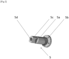
- FIG. 2 illustrates the hollow shaft 5. It can be seen that it comprises a cylindrical body 5a, provided at one end with a flat 5b and at the other end with a base 5c also cylindrical, this base being provided with perforations designed to cooperate with a fixing system of the rod and bolt type so as to secure the hollow shaft 5 to the stator of the motor 3.
- the hollow shaft 5 is pierced through and through so as to obtain a slot 5d, through which control cables and power supply cables or hoses of the motor 3 can pass.
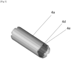
- FIG 3 illustrates a hollow cylinder 4a comprising, near each of its ends, a set of peripheral cutouts 4d associated with axial cutouts 4e each extending from one end of the hollow cylinder 4a to a peripheral cutout 4d.
- the set formed by an axial cutout 4e and a peripheral cutout 4d is designed so that a shoulder 4f provided in a flange 4b,4c can be inserted in translation into the axial cutout 4e and then locked in the peripheral cutout 4d by relative rotation of the flange 4b,4c relative to the hollow cylinder 4a.
- each flange 4b,4c comprises at least two 4f shoulders, arranged in particular diametrically opposite. In order to have better support, a higher number of 4f shoulders is considered, for example five shoulders, arranged with a substantially constant angular distance between them.
- each shoulder 4f is provided with a groove 4g on the ends coming into abutment with the hollow cylinder 4a during rotation of the flange 4b, 4c, so that the hollow cylinder 4a engages in the groove 4g during rotation.
- a groove 4g makes it possible to limit the radial translation of the flange 4b, 4c.
- a rear flange 4c includes an axial opening 4h and is secured to the hollow shaft 5 and the stator of the motor 3 by means of removable securing means, for example screw/bolt assemblies or blind rivets. Once secured, the axial opening 4h of the rear flange 4c corresponds with the outside diameter of the body of the hollow shaft 5 so that the control cables and power cables or hoses of the motor can be connected to the outside of the cylindrical casing 4a,4b,4c.
- two rear flanges 4c are used to prevent possible loosening of the hollow cylinder 4a due to vibrations of the system. They are then locked in opposite directions of rotation.
- the use of two flanges 4c thus fixed to the hollow cylinder 4a and secured together by means of the removable securing means with the hollow shaft 5 makes it possible to eliminate the risk of disengagement of a flange 4c due to a rotation opposite to the direction of engagement of the shoulders 4f.
- a front flange 4b also comprises an axial opening 4i, allowing, unlike the rear flanges 4c, the output shaft of the epicyclic gear train 2 to pass through.
- a front flange 4b also comprises at least two shoulders 4f each capable of cooperating with an assembly formed by an axial cutout 4e and a cutout peripheral 4d near one end of the hollow cylinder 4a.
- a groove 4g is also present at the end of each shoulder 4f intended to come into contact with the cylinder 4a.
- a front flange 4b is secured to the housing of the epicyclic gear train 2 by means of removable securing means, for example screw/bolt assemblies or blind rivets. Once secured, the axial opening of the rear flange 4c corresponds with the output shaft of the epicyclic gear train 2 so that the cylindrical casing 4a,4b,4c is not subjected to the rotation of the output shaft.
- two front flanges 4b are used. They are then locked in rotation in opposite directions.
- the use of two flanges 4b thus fixed to the first outer casing and secured together by means of the removable securing means with the hollow shaft 5 makes it possible to eliminate the disengagement of a flange due to a rotation opposite to the direction of engagement of the shoulders in the hollow cylinder 4a.
- the cylindrical casing 4a, 4b, 4c thus formed insulates the geared motor 1 from the outside while providing an outlet on the one hand for control cables and power supply cables or hoses of the motor 3 and on the other hand for the output shaft of the epicyclic gear train 2.
- the cylindrical casing 4a, 4b, 4c makes it possible to perfectly isolate the motor from the outside, thus protecting it from possible damage.
- the hollow shaft 5 and the epicyclic output shaft 2 define the axis of rotation of the geared motor 1, so that it can be easily integrated into a mechanical system without inducing eccentricity of movement. Indeed, it is easier to center an axis relative to the mechanism than to center an axis linked to the rotor of a motor and a stator having a spatial extension.
- the cylindrical casing 4a, 4b, 4c has the additional advantage of being able to be easily dismantled for the maintenance of the motor or epicyclic gear train. The state of the art shows sealed geared motors on this point, the maintenance of which involves destructive dismantling of the casing, thus implying that a new casing must be recreated afterwards.
- the cylindrical casing 4a, 4b, 4c also has insulation from dust and/or water by adding sealing means at the junction between the flanges 4b, 4c and the cylinder 4a, between the rear flanges 4c and the hollow shaft 5 and/or between the front flanges 4b and the output shaft of the epicyclic gear train 2.
- the geared motor 1 thus formed is arranged in a drum held at its two ends by flanges 6b, 6c, making it possible to transfer the rotational movement of the output shaft of the epicyclic gear train 2 to the drum.
- the front flange 6b illustrated by the figure 6 , is fixed on the output shaft of the epicyclic gear train 2 and on the drum. It comprises an axis of rotation 6e as well as external fixing means 6f.
- the 6c rear flange illustrated by the figure 7 , comprises a light 6g provided with a bearing 6h through which the hollow shaft 5 is inserted.
- the bearing 6h can be a ball bearing or a mechanical seal. It allows the decoupling of the rotation of the drum relative to the hollow shaft 5.
- the rear flange 6c comprises external fixing means 6i.
- flanges 6b,6c ensure that the cylindrical casing 4a,4b,4b and the drum are coaxial, so as to avoid the formation of a reactive moment resulting from an eccentricity of the drum which could lead to variations in the speed of unwinding or winding of the rope.
- the drum provides a contact or fixing surface for a larger rotating element. This is particularly the case when the tubular motor is used in a winding/unwinding system, such as that of a removable cover.
- the drum may be cylindrical or prismatic. Examples include square or hexagonal prisms providing bearing surfaces for the drum to improve torque communication to a rotating surface.
- the tubular motor thus defined can accept indifferently any motor with dimensions compatible with the cylindrical casing, arranged axially with respect to the epicyclic gear train. Thus, even if it is common to have electric geared motors with such a configuration, the latter have a low rotation speed and/or a low torque.
- Axial hydraulic or pneumatic geared motors are not currently available. Such axial hydraulic or pneumatic geared motors provide high torque from hydraulic or pneumatic circuits on board a vehicle, particularly heavy goods vehicles or railway vehicles, while maintaining a small footprint.
- an actuation system 10 comprises a tubular motor as described above arranged in a casing 11, provided with a fixing 11a, 11b of the hollow axis 5 of the rear flange 6c, and a drive assembly 12b, 12c coupled to the front flange 6b.
- the casing 11 is in particular fixed to the chassis of a vehicle or a building so as to limit the return reaction of the actuation.
- the fastener 11a, 11b forms a clamp cooperating with the flats 5b formed on the hollow shaft 5 so as to prevent rotation thereof.
- the rotation of the motor is then transmitted to the drum 7.
- the drum 7 allows you to roll up or unroll any canvas, fabric, blanket, conveyor belt, cable or rope.
- the actuation system 10 is rendered inoperable.
- the attachment 11a, 11b can be opened so that the hollow shaft 5 is free to rotate, while being held in position by the rear flange 6c.
- the motor connections, in particular hydraulic or pneumatic, are disconnected using quick connectors, so as to reduce their inertia.
- a crank 12a can then be connected to the drive assembly 12b, 12c so as to be able to impart rotation to the drum via the axis of the front flange 6b.
- the functions of the actuation system are restored in a manual operating mode.
- the drive assembly 12b, 12c may include gear wheels, pinions and/or crown gears.
- the judicious choice of the gear ratios of the selected elements allows the manual operation of the actuation system with a restricted force.
- the drive assembly includes an element, not illustrated, arranged integrally with the axis 6e and meshed with the other elements.
- fixing 11a, 11b and the drive assembly 12b, 12c are integral with the casing and the tubular motor by means of the flanges. They then contribute to maintaining the tubular motor in axial position.
- a gasket illustrated on the figure 8 secured to the covering 11, keeps the hollow axis aligned when the fixing 11a, 11b is open.
- Such an actuation system avoids the need for an expensive, bulky and high-maintenance clutch to switch from engine actuation to manual actuation.
- maintenance of an actuation system according to the invention allows removal of the tubular motor for exchange or repair while the drum remains in place in the system. This is particularly advantageous in that it is not necessary to remove the canvas, fabric, cover, conveyor belt, cable or rope wound on the drum. The duration and cost of maintenance are thus greatly reduced.
Landscapes
- Engineering & Computer Science (AREA)
- General Engineering & Computer Science (AREA)
- Mechanical Engineering (AREA)
- Power Engineering (AREA)
- Connection Of Motors, Electrical Generators, Mechanical Devices, And The Like (AREA)
- Retarders (AREA)
Claims (11)
- Getriebemotor, der einen Planetenradsatz (2) umfasst, der mit einer Abtriebswelle eines Motors (3) gekoppelt ist, der eine zylindrische Umhüllung (4a, 4b, 4c), die den Getriebemotor (1) von der Außenseite isoliert, und eine Hohlwelle (5) umfasst, die mit dem Stator des Motors (3) verbunden und mit der Abtriebswelle des Planetenradsatzes (2) ausgerichtet ist, wobei die zylindrische Umhüllung (4a, 4b, 4c) einen Hohlzylinder (4a) umfasst, dadurch gekennzeichnet, dass die zylindrische Umhüllung (4a, 4b, 4c) ferner zwei vordere Flansche (4b) und zwei hintere Flansche (4c) umfasst,wobei die beiden vorderen Flansche (4b) fest mit dem Gehäuse des Planetenradsatzes (2) verbunden sind, wobei die beiden hinteren Flansche (4c) fest mit der Hohlwelle (5) verbunden sind,wobei der Hohlzylinder (4a) in der Nähe jedes seiner Enden mit einer Anordnung von peripheren Aussparungen (4d) versehen ist, die mit axialen Aussparungen (4e) verbunden sind, die sich jeweils von einem Ende des Hohlzylinders (4a) bis zu einer peripheren Aussparung (4d) erstrecken, wobei die vorderen Flansche (4b) und die hinteren Flansche (4c) jeweils mit axialen Öffnungen und mindestens zwei Schultern (4f) versehen sind, wobei jede Schulter (4f) dazu ausgelegt ist, mit einer Anordnung zusammenzuwirken, die aus einer axialen Aussparung (4e) und einer peripheren Aussparung (4d) in der Nähe eines Endes des Hohlzylinders (4a) gebildet ist, um die zylindrische Umhüllung (4a, 4b, 4c) zu bilden und diese durch Drehung der Flansche (4b, 4c) im Verhältnis zum Hohlzylinder (4a) zu verriegeln,wobei jeder der beiden vorderen Flansche (4b) und jeder der beiden hinteren Flansche (4c) in entgegengesetzten Drehrichtungen verriegelt sind.
- Getriebemotor nach Anspruch 1, wobei die Öffnungen der hinteren Flansche (4c) es gestatten, die Hohlwelle (5) aufzunehmen.
- Getriebemotor nach einem der Ansprüche 1 oder 2, wobei die Öffnungen der vorderen Flansche (4b) es gestatten, die Abtriebswelle des Planetenradsatzes aufzunehmen.
- Getriebemotor nach einem der vorhergehenden Ansprüche, wobei jeder Flansch fünf Schultern umfasst und der Hohlzylinder (4a) eine entsprechende Anzahl von Anordnungen aus radialen und axialen Aussparungen umfasst.
- Getriebemotor nach einem der vorhergehenden Ansprüche, wobei jede Schulter (4f) mit einer Nut (4g) versehen ist, so dass der Hohlzylinder (4a) bei der Relativdrehung der Schulter (4f) und des Hohlzylinders (4a) in die Nut (4g) in Eingriff gelangt.
- Getriebemotor nach einem der vorhergehenden Ansprüche, wobei der Motor (3) ein elektrischer, hydraulischer, pneumatischer oder ölpneumatischer Motor ist.
- Getriebemotor nach einem der vorhergehenden Ansprüche, wobei die Hohlwelle (5) eine Öffnung (5d) umfasst, durch die die Stromversorgung und Steuerung des Motors (3) durch die zylindrische Umhüllung (4a, 4b, 4c) verläuft.
- Rohrmotor, der einen Getriebemotor 1 nach einem der Ansprüche 1 bis 7 umfasst, dadurch gekennzeichnet, dass er eine Drehtrommel, die sich um die zylindrische Umhüllung (4a, 4b, 4c) erstreckt, eine vordere Schutzabdeckung (6b), die fest mit der Abtriebsachse des Planetenradsatzes des Getriebemotors verbunden ist, und eine hintere Schutzabdeckung (6c) umfasst, die frei drehbar auf der Hohlwelle (5) des Getriebemotors anliegt, wobei die Schutzabdeckungen fest mit der Trommel verbunden sind, so dass die Drehung der Abtriebsachse des Planetenradsatzes auf die Trommel übertragen wird und die Drehachse der Drehtrommel koaxial mit der Drehachse des Getriebemotors (1) ist, die sich durch die Hohlwelle (5) und die Abtriebswelle des Planetenradsatzes (2) erstreckt.
- Rohrmotor nach Anspruch 8, wobei die hintere Schutzabdeckung (6c) mit einem Lager (6h) versehen ist, das mit der Hohlwelle (5) zusammenwirkt, um den Getriebemotor (1) von der Drehung der Drehtrommel zu dekorrelieren.
- Betätigungssystem, das einen Rohrmotor nach einem der Ansprüche 8 oder 9 umfasst, der in einer Verkleidung (11) angeordnet ist, wobei das Betätigungssystem ferner eine Befestigung (11a, 11b) der Hohlachse der hinteren Schutzabdeckung (6c) an der Verkleidung (11) und eine Antriebsanordnung (12b, 12c) umfasst, die mit der vorderen Schutzabdeckung (6b) gekoppelt und dazu ausgelegt ist, eine Kurbelvorrichtung (12a) aufzunehmen, wobei die Befestigung (11a, 11b) so ausgestaltet ist, dass sie geöffnet wird, wenn das Betätigungssystem mit der Kurbelvorrichtung (12a) betätigt wird.
- Betätigungssystem nach Anspruch 10, wobei der Rohrmotor mit schnell trennbaren Steckverbindungen versehen ist, um den Rohrmotor von seiner Stromquelle zu isolieren, wenn das Betätigungssystem mit der Kurbelvorrichtung (12a) betätigt wird.
Applications Claiming Priority (3)
| Application Number | Priority Date | Filing Date | Title |
|---|---|---|---|
| FR2007238A FR3112373B1 (fr) | 2020-07-08 | 2020-07-08 | Motoréducteur à enveloppe cylindrique et moteur tubulaire correspondant. |
| FR2009887A FR3112374B1 (fr) | 2020-07-08 | 2020-09-29 | Motoréducteur à enveloppe cylindrique et moteur tubulaire correspondant. |
| PCT/FR2021/051248 WO2022008840A1 (fr) | 2020-07-08 | 2021-07-06 | Motoréducteur à enveloppe cylindrique et moteur tubulaire correspondant |
Publications (3)
| Publication Number | Publication Date |
|---|---|
| EP4179610A1 EP4179610A1 (de) | 2023-05-17 |
| EP4179610B1 true EP4179610B1 (de) | 2024-10-16 |
| EP4179610C0 EP4179610C0 (de) | 2024-10-16 |
Family
ID=72801690
Family Applications (1)
| Application Number | Title | Priority Date | Filing Date |
|---|---|---|---|
| EP21746524.4A Active EP4179610B1 (de) | 2020-07-08 | 2021-07-06 | Getriebemotor mit einem zylindergehäuse und entsprechender rohrmotor |
Country Status (8)
| Country | Link |
|---|---|
| US (1) | US12352351B2 (de) |
| EP (1) | EP4179610B1 (de) |
| CN (1) | CN116250168A (de) |
| CA (1) | CA3183964A1 (de) |
| ES (1) | ES3001907T3 (de) |
| FR (2) | FR3112373B1 (de) |
| PL (1) | PL4179610T3 (de) |
| WO (1) | WO2022008840A1 (de) |
Families Citing this family (1)
| Publication number | Priority date | Publication date | Assignee | Title |
|---|---|---|---|---|
| USD1124071S1 (en) * | 2024-10-16 | 2026-04-28 | Guangdong Maijie Industrial Co., Ltd. | Gear motor |
Family Cites Families (8)
| Publication number | Priority date | Publication date | Assignee | Title |
|---|---|---|---|---|
| JP2002276742A (ja) * | 2001-03-09 | 2002-09-25 | Shunho Kyo | 内歯車が外方旋回するドラム式モータ |
| US6672402B2 (en) * | 2001-12-27 | 2004-01-06 | Black & Decker Inc. | Combined fastenerless motor end cap and output device mounting |
| DE102005030217A1 (de) * | 2005-06-29 | 2007-01-04 | Robert Bosch Gmbh | Elektromotor und Getriebe-Antriebseinheit für Stellantriebe im Kraftfahrzeug |
| JP5604338B2 (ja) * | 2011-03-07 | 2014-10-08 | Ntn株式会社 | 電気自動車用駆動装置 |
| FR3016013B1 (fr) * | 2013-12-30 | 2016-02-12 | Chassis Brakes Int Bv | Actionneur de frein a tambour avec motorisation par emboitement a jeu angulaire |
| JP6478863B2 (ja) * | 2015-07-31 | 2019-03-06 | 株式会社ミツバ | アクチュエータおよび車両ドア開閉用アクチュエータ |
| DE102016112036A1 (de) * | 2016-06-30 | 2018-01-04 | Interroll Holding Ag | Antriebseinheit für einen Trommelmotor, Trommelmotor, Hinterflansch und Herstellungsverfahren |
| JP7009723B2 (ja) * | 2018-05-29 | 2022-01-26 | ▲無▼▲錫▼小天鵝電器有限公司 | ドラム式洗濯機用の制動器及びドラム式洗濯機 |
-
2020
- 2020-07-08 FR FR2007238A patent/FR3112373B1/fr active Active
- 2020-09-29 FR FR2009887A patent/FR3112374B1/fr active Active
-
2021
- 2021-07-06 EP EP21746524.4A patent/EP4179610B1/de active Active
- 2021-07-06 US US18/005,322 patent/US12352351B2/en active Active
- 2021-07-06 PL PL21746524.4T patent/PL4179610T3/pl unknown
- 2021-07-06 ES ES21746524T patent/ES3001907T3/es active Active
- 2021-07-06 CN CN202180048940.6A patent/CN116250168A/zh active Pending
- 2021-07-06 CA CA3183964A patent/CA3183964A1/fr active Pending
- 2021-07-06 WO PCT/FR2021/051248 patent/WO2022008840A1/fr not_active Ceased
Also Published As
| Publication number | Publication date |
|---|---|
| ES3001907T3 (en) | 2025-03-06 |
| FR3112374B1 (fr) | 2023-04-21 |
| FR3112373B1 (fr) | 2023-04-21 |
| US12352351B2 (en) | 2025-07-08 |
| WO2022008840A1 (fr) | 2022-01-13 |
| FR3112374A1 (fr) | 2022-01-14 |
| US20230272849A1 (en) | 2023-08-31 |
| EP4179610A1 (de) | 2023-05-17 |
| CN116250168A (zh) | 2023-06-09 |
| CA3183964A1 (fr) | 2022-01-13 |
| FR3112373A1 (fr) | 2022-01-14 |
| EP4179610C0 (de) | 2024-10-16 |
| PL4179610T3 (pl) | 2025-03-31 |
Similar Documents
| Publication | Publication Date | Title |
|---|---|---|
| CA2619927C (fr) | Turbopropulseur a helice a pas reglable | |
| EP3854680B1 (de) | Drehflügelflugzeug mit einem übertragungssystem, das mit einem elektrischen notantriebsmotor ausgestattet ist | |
| EP2372187B1 (de) | Reduktionsgetriebe und elektrisches Stellglied mit so einem Reduktionsgetriebe | |
| EP0790385A1 (de) | Rolladenbetätigungsvorrichtung | |
| EP3581416A1 (de) | Getriebevorrichtung, insbesondere für elektrofahrzeug | |
| EP4179610B1 (de) | Getriebemotor mit einem zylindergehäuse und entsprechender rohrmotor | |
| EP2783062A2 (de) | Rohrförmiges elektrisches stellglied für einen heimautomatisierungsbildschirm,. verfahren zur montage eines solchen stellgliedes und anlage mit einem solchen stellglied | |
| FR3064620A1 (fr) | Systeme de transfert de fluide a actionneurs munis de reducteurs de vitesse reversibles | |
| FR2975842A1 (fr) | Dispositif d'alimentation electrique d'au moins un equipement d'un rotor tournant d'un aeronef, et aeronef | |
| EP4339104B1 (de) | Antriebsanordnung mit einem getriebe, mehreren elektromotoren und mindestens einem versetzten kupplungssystem, luftfahrzeug mit mindestens einer solchen antriebsanordnung | |
| EP1653593B1 (de) | Doppelausgangs-Elektromotor | |
| EP0320416B1 (de) | Drehbarer Kollektor zur Speisung eines Motors von Stoffaufwickelvorrichtungen oder von anderen Abschliessvorrichtungen mit integrierter Notfunktion | |
| EP2816253B1 (de) | Planetengetriebe für aufroll- und abrollstellglied | |
| EP3140238B1 (de) | Modulare bordwinde | |
| EP0775798A1 (de) | Drehantriebsvorrichtung zum Drehen der Rolle eines Rolladens | |
| EP0490755B1 (de) | Antriebssystem zwischen einer Antriebswelle und zwei angetriebenen Einheiten, insbesondere für ein Drehflügelflugzeug | |
| FR3105812A1 (fr) | Train d’engrenages imbriqué à deux pignons solaires | |
| EP4279308B1 (de) | Hybridantriebsbaugruppe für ein fahrzeug | |
| EP0768981A1 (de) | Motorangetriebene winde,zur verankerung von schiffen | |
| EP1691068A1 (de) | Vorrichtung zum Anlassen einer Brennkraftmaschine | |
| EP4406851A1 (de) | Elektrische antriebsanordnung mit mehreren an eine einzige eingangswelle eines übertragungssystems gekoppelten elektromotoren, luftfahrzeug mit mindestens einer solchen elektrischen antriebsanordnung | |
| FR2996275A1 (fr) | Dispositif d'entrainement d'une poulie destinee a entrainer un cable de traction d'un telepherique, notament un telesiege ou telecabine | |
| FR2988456A1 (fr) | Dispositif reducteur de vitesse comprenant un train epicycloidal et une motorisation | |
| FR2747089A1 (fr) | Motoreducteur pour essuie-glace de vehicule automobile | |
| EP3121439A1 (de) | Einheit aus elastisch gekoppeltem zahnrad mit zahnradhalterung eines anlassers |
Legal Events
| Date | Code | Title | Description |
|---|---|---|---|
| STAA | Information on the status of an ep patent application or granted ep patent |
Free format text: STATUS: UNKNOWN |
|
| STAA | Information on the status of an ep patent application or granted ep patent |
Free format text: STATUS: THE INTERNATIONAL PUBLICATION HAS BEEN MADE |
|
| PUAI | Public reference made under article 153(3) epc to a published international application that has entered the european phase |
Free format text: ORIGINAL CODE: 0009012 |
|
| STAA | Information on the status of an ep patent application or granted ep patent |
Free format text: STATUS: REQUEST FOR EXAMINATION WAS MADE |
|
| 17P | Request for examination filed |
Effective date: 20230131 |
|
| AK | Designated contracting states |
Kind code of ref document: A1 Designated state(s): AL AT BE BG CH CY CZ DE DK EE ES FI FR GB GR HR HU IE IS IT LI LT LU LV MC MK MT NL NO PL PT RO RS SE SI SK SM TR |
|
| DAV | Request for validation of the european patent (deleted) | ||
| DAX | Request for extension of the european patent (deleted) | ||
| GRAP | Despatch of communication of intention to grant a patent |
Free format text: ORIGINAL CODE: EPIDOSNIGR1 |
|
| STAA | Information on the status of an ep patent application or granted ep patent |
Free format text: STATUS: GRANT OF PATENT IS INTENDED |
|
| INTG | Intention to grant announced |
Effective date: 20240524 |
|
| GRAS | Grant fee paid |
Free format text: ORIGINAL CODE: EPIDOSNIGR3 |
|
| GRAA | (expected) grant |
Free format text: ORIGINAL CODE: 0009210 |
|
| STAA | Information on the status of an ep patent application or granted ep patent |
Free format text: STATUS: THE PATENT HAS BEEN GRANTED |
|
| AK | Designated contracting states |
Kind code of ref document: B1 Designated state(s): AL AT BE BG CH CY CZ DE DK EE ES FI FR GB GR HR HU IE IS IT LI LT LU LV MC MK MT NL NO PL PT RO RS SE SI SK SM TR |
|
| REG | Reference to a national code |
Ref country code: GB Ref legal event code: FG4D Free format text: NOT ENGLISH |
|
| REG | Reference to a national code |
Ref country code: CH Ref legal event code: EP |
|
| REG | Reference to a national code |
Ref country code: IE Ref legal event code: FG4D Free format text: LANGUAGE OF EP DOCUMENT: FRENCH |
|
| REG | Reference to a national code |
Ref country code: DE Ref legal event code: R096 Ref document number: 602021020392 Country of ref document: DE |
|
| U01 | Request for unitary effect filed |
Effective date: 20241106 |
|
| U07 | Unitary effect registered |
Designated state(s): AT BE BG DE DK EE FI FR IT LT LU LV MT NL PT RO SE SI Effective date: 20241115 |
|
| REG | Reference to a national code |
Ref country code: ES Ref legal event code: FG2A Ref document number: 3001907 Country of ref document: ES Kind code of ref document: T3 Effective date: 20250306 |
|
| PG25 | Lapsed in a contracting state [announced via postgrant information from national office to epo] |
Ref country code: IS Free format text: LAPSE BECAUSE OF FAILURE TO SUBMIT A TRANSLATION OF THE DESCRIPTION OR TO PAY THE FEE WITHIN THE PRESCRIBED TIME-LIMIT Effective date: 20250216 Ref country code: HR Free format text: LAPSE BECAUSE OF FAILURE TO SUBMIT A TRANSLATION OF THE DESCRIPTION OR TO PAY THE FEE WITHIN THE PRESCRIBED TIME-LIMIT Effective date: 20241016 |
|
| PG25 | Lapsed in a contracting state [announced via postgrant information from national office to epo] |
Ref country code: NO Free format text: LAPSE BECAUSE OF FAILURE TO SUBMIT A TRANSLATION OF THE DESCRIPTION OR TO PAY THE FEE WITHIN THE PRESCRIBED TIME-LIMIT Effective date: 20250116 |
|
| PG25 | Lapsed in a contracting state [announced via postgrant information from national office to epo] |
Ref country code: GR Free format text: LAPSE BECAUSE OF FAILURE TO SUBMIT A TRANSLATION OF THE DESCRIPTION OR TO PAY THE FEE WITHIN THE PRESCRIBED TIME-LIMIT Effective date: 20250117 |
|
| PG25 | Lapsed in a contracting state [announced via postgrant information from national office to epo] |
Ref country code: RS Free format text: LAPSE BECAUSE OF FAILURE TO SUBMIT A TRANSLATION OF THE DESCRIPTION OR TO PAY THE FEE WITHIN THE PRESCRIBED TIME-LIMIT Effective date: 20250116 |
|
| PG25 | Lapsed in a contracting state [announced via postgrant information from national office to epo] |
Ref country code: SM Free format text: LAPSE BECAUSE OF FAILURE TO SUBMIT A TRANSLATION OF THE DESCRIPTION OR TO PAY THE FEE WITHIN THE PRESCRIBED TIME-LIMIT Effective date: 20241016 |
|
| PG25 | Lapsed in a contracting state [announced via postgrant information from national office to epo] |
Ref country code: SK Free format text: LAPSE BECAUSE OF FAILURE TO SUBMIT A TRANSLATION OF THE DESCRIPTION OR TO PAY THE FEE WITHIN THE PRESCRIBED TIME-LIMIT Effective date: 20241016 |
|
| PG25 | Lapsed in a contracting state [announced via postgrant information from national office to epo] |
Ref country code: CZ Free format text: LAPSE BECAUSE OF FAILURE TO SUBMIT A TRANSLATION OF THE DESCRIPTION OR TO PAY THE FEE WITHIN THE PRESCRIBED TIME-LIMIT Effective date: 20241016 |
|
| PLBE | No opposition filed within time limit |
Free format text: ORIGINAL CODE: 0009261 |
|
| STAA | Information on the status of an ep patent application or granted ep patent |
Free format text: STATUS: NO OPPOSITION FILED WITHIN TIME LIMIT |
|
| U20 | Renewal fee for the european patent with unitary effect paid |
Year of fee payment: 5 Effective date: 20250723 |
|
| 26N | No opposition filed |
Effective date: 20250717 |
|
| PGFP | Annual fee paid to national office [announced via postgrant information from national office to epo] |
Ref country code: ES Payment date: 20250812 Year of fee payment: 5 |
|
| PGFP | Annual fee paid to national office [announced via postgrant information from national office to epo] |
Ref country code: PL Payment date: 20250702 Year of fee payment: 5 |
|
| REG | Reference to a national code |
Ref country code: CH Ref legal event code: H13 Free format text: ST27 STATUS EVENT CODE: U-0-0-H10-H13 (AS PROVIDED BY THE NATIONAL OFFICE) Effective date: 20260224 |
|
| GBPC | Gb: european patent ceased through non-payment of renewal fee |
Effective date: 20250706 |
|
| PG25 | Lapsed in a contracting state [announced via postgrant information from national office to epo] |
Ref country code: GB Free format text: LAPSE BECAUSE OF NON-PAYMENT OF DUE FEES Effective date: 20250706 |
|
| PG25 | Lapsed in a contracting state [announced via postgrant information from national office to epo] |
Ref country code: CH Free format text: LAPSE BECAUSE OF NON-PAYMENT OF DUE FEES Effective date: 20250731 |