EP4179719B1 - Formteil für ein mobiles endgerät mit sende und/oder empfangsvorrichtung aus kohlenstofffaserverstärktem kunststoff - Google Patents
Formteil für ein mobiles endgerät mit sende und/oder empfangsvorrichtung aus kohlenstofffaserverstärktem kunststoff Download PDFInfo
- Publication number
- EP4179719B1 EP4179719B1 EP21749300.6A EP21749300A EP4179719B1 EP 4179719 B1 EP4179719 B1 EP 4179719B1 EP 21749300 A EP21749300 A EP 21749300A EP 4179719 B1 EP4179719 B1 EP 4179719B1
- Authority
- EP
- European Patent Office
- Prior art keywords
- antenna
- shaped part
- carbon
- reinforced plastic
- fiber
- Prior art date
- Legal status (The legal status is an assumption and is not a legal conclusion. Google has not performed a legal analysis and makes no representation as to the accuracy of the status listed.)
- Active
Links
Images

Classifications
-
- H—ELECTRICITY
- H04—ELECTRIC COMMUNICATION TECHNIQUE
- H04B—TRANSMISSION
- H04B1/00—Details of transmission systems, not covered by a single one of groups H04B3/00 - H04B13/00; Details of transmission systems not characterised by the medium used for transmission
- H04B1/38—Transceivers, i.e. devices in which transmitter and receiver form a structural unit and in which at least one part is used for functions of transmitting and receiving
- H04B1/3827—Portable transceivers
- H04B1/3888—Arrangements for carrying or protecting transceivers
-
- H—ELECTRICITY
- H04—ELECTRIC COMMUNICATION TECHNIQUE
- H04M—TELEPHONIC COMMUNICATION
- H04M1/00—Substation equipment, e.g. for use by subscribers
- H04M1/02—Constructional features of telephone sets
- H04M1/18—Telephone sets specially adapted for use in ships, mines, or other places exposed to adverse environment
- H04M1/185—Improving the shock resistance of the housing, e.g. by increasing the rigidity
-
- A—HUMAN NECESSITIES
- A45—HAND OR TRAVELLING ARTICLES
- A45C—PURSES; LUGGAGE; HAND CARRIED BAGS
- A45C11/00—Receptacles for purposes not provided for in groups A45C1/00-A45C9/00
-
- A—HUMAN NECESSITIES
- A45—HAND OR TRAVELLING ARTICLES
- A45C—PURSES; LUGGAGE; HAND CARRIED BAGS
- A45C11/00—Receptacles for purposes not provided for in groups A45C1/00-A45C9/00
- A45C11/002—Receptacles for purposes not provided for in groups A45C1/00-A45C9/00 for storing portable handheld communication devices, e.g. pagers or smart phones
-
- A—HUMAN NECESSITIES
- A45—HAND OR TRAVELLING ARTICLES
- A45C—PURSES; LUGGAGE; HAND CARRIED BAGS
- A45C3/00—Flexible luggage; Handbags
- A45C3/001—Flexible materials therefor
-
- C—CHEMISTRY; METALLURGY
- C08—ORGANIC MACROMOLECULAR COMPOUNDS; THEIR PREPARATION OR CHEMICAL WORKING-UP; COMPOSITIONS BASED THEREON
- C08J—WORKING-UP; GENERAL PROCESSES OF COMPOUNDING; AFTER-TREATMENT NOT COVERED BY SUBCLASSES C08B, C08C, C08F, C08G or C08H
- C08J5/00—Manufacture of articles or shaped materials containing macromolecular substances
- C08J5/24—Impregnating materials with prepolymers which can be polymerised in situ, e.g. manufacture of prepregs
- C08J5/241—Impregnating materials with prepolymers which can be polymerised in situ, e.g. manufacture of prepregs using inorganic fibres
- C08J5/243—Impregnating materials with prepolymers which can be polymerised in situ, e.g. manufacture of prepregs using inorganic fibres using carbon fibres
-
- C—CHEMISTRY; METALLURGY
- C08—ORGANIC MACROMOLECULAR COMPOUNDS; THEIR PREPARATION OR CHEMICAL WORKING-UP; COMPOSITIONS BASED THEREON
- C08J—WORKING-UP; GENERAL PROCESSES OF COMPOUNDING; AFTER-TREATMENT NOT COVERED BY SUBCLASSES C08B, C08C, C08F, C08G or C08H
- C08J5/00—Manufacture of articles or shaped materials containing macromolecular substances
- C08J5/24—Impregnating materials with prepolymers which can be polymerised in situ, e.g. manufacture of prepregs
- C08J5/241—Impregnating materials with prepolymers which can be polymerised in situ, e.g. manufacture of prepregs using inorganic fibres
- C08J5/244—Impregnating materials with prepolymers which can be polymerised in situ, e.g. manufacture of prepregs using inorganic fibres using glass fibres
-
- H—ELECTRICITY
- H01—ELECTRIC ELEMENTS
- H01Q—ANTENNAS, i.e. RADIO AERIALS
- H01Q1/00—Details of, or arrangements associated with, antennas
- H01Q1/12—Supports; Mounting means
- H01Q1/22—Supports; Mounting means by structural association with other equipment or articles
- H01Q1/24—Supports; Mounting means by structural association with other equipment or articles with receiving set
- H01Q1/241—Supports; Mounting means by structural association with other equipment or articles with receiving set used in mobile communications, e.g. GSM
- H01Q1/242—Supports; Mounting means by structural association with other equipment or articles with receiving set used in mobile communications, e.g. GSM specially adapted for hand-held use
- H01Q1/243—Supports; Mounting means by structural association with other equipment or articles with receiving set used in mobile communications, e.g. GSM specially adapted for hand-held use with built-in antennas
-
- H—ELECTRICITY
- H01—ELECTRIC ELEMENTS
- H01Q—ANTENNAS, i.e. RADIO AERIALS
- H01Q1/00—Details of, or arrangements associated with, antennas
- H01Q1/36—Structural form of radiating elements, e.g. cone, spiral, umbrella; Particular materials used therewith
-
- H—ELECTRICITY
- H01—ELECTRIC ELEMENTS
- H01Q—ANTENNAS, i.e. RADIO AERIALS
- H01Q1/00—Details of, or arrangements associated with, antennas
- H01Q1/42—Housings not intimately mechanically associated with radiating elements, e.g. radome
-
- H—ELECTRICITY
- H01—ELECTRIC ELEMENTS
- H01Q—ANTENNAS, i.e. RADIO AERIALS
- H01Q1/00—Details of, or arrangements associated with, antennas
- H01Q1/42—Housings not intimately mechanically associated with radiating elements, e.g. radome
- H01Q1/422—Housings not intimately mechanically associated with radiating elements, e.g. radome comprising two or more layers of dielectric material
-
- H—ELECTRICITY
- H01—ELECTRIC ELEMENTS
- H01Q—ANTENNAS, i.e. RADIO AERIALS
- H01Q1/00—Details of, or arrangements associated with, antennas
- H01Q1/52—Means for reducing coupling between antennas; Means for reducing coupling between an antenna and another structure
-
- H—ELECTRICITY
- H05—ELECTRIC TECHNIQUES NOT OTHERWISE PROVIDED FOR
- H05K—PRINTED CIRCUITS; CASINGS OR CONSTRUCTIONAL DETAILS OF ELECTRIC APPARATUS; MANUFACTURE OF ASSEMBLAGES OF ELECTRICAL COMPONENTS
- H05K9/00—Screening of apparatus or components against electric or magnetic fields
- H05K9/0007—Casings
- H05K9/0043—Casings being flexible containers, e.g. pouch, pocket, bag
-
- H—ELECTRICITY
- H05—ELECTRIC TECHNIQUES NOT OTHERWISE PROVIDED FOR
- H05K—PRINTED CIRCUITS; CASINGS OR CONSTRUCTIONAL DETAILS OF ELECTRIC APPARATUS; MANUFACTURE OF ASSEMBLAGES OF ELECTRICAL COMPONENTS
- H05K9/00—Screening of apparatus or components against electric or magnetic fields
- H05K9/0007—Casings
- H05K9/0047—Casings being rigid plastic containers having conductive particles, fibres or mesh embedded therein
-
- C—CHEMISTRY; METALLURGY
- C08—ORGANIC MACROMOLECULAR COMPOUNDS; THEIR PREPARATION OR CHEMICAL WORKING-UP; COMPOSITIONS BASED THEREON
- C08J—WORKING-UP; GENERAL PROCESSES OF COMPOUNDING; AFTER-TREATMENT NOT COVERED BY SUBCLASSES C08B, C08C, C08F, C08G or C08H
- C08J2300/00—Characterised by the use of unspecified polymers
- C08J2300/22—Thermoplastic resins
Definitions
- the invention relates to a molded part for a mobile terminal with a transmitting and/or receiving device made of carbon fiber reinforced plastic.
- the housing of the mobile device is manufactured from carbon fiber reinforced plastic.
- the carbon fiber reinforced plastic has similar strength values to current molded parts made of aluminum/magnesium cast. What is special about the carbon fiber reinforced plastic is that it can absorb impacts, as is sometimes the case when a device is dropped from hand height, whereby the absorbed kinetic energy is dissipated in the carbon fiber composite and is not passed on to other components.
- Another advantage of the housing made of carbon fiber reinforced plastic is its low weight.
- the one-sided weight of the smartphone is also perceived as annoying.
- the weight of folding smartphones, i.e. smartphones with foldable displays, which are expected in the near future, will increase considerably because each molded part will weigh approximately the same as a single smartphone today.
- carbon fiber composites has a surprising side effect. Due to the high electrical conductivity of the carbon fibers, a housing wall for a mobile phone, a tablet computer or a smartphone has the effect of a Faraday cage. The effect is more pronounced the more directions the carbon fiber filaments are laid in. There are unidirectional
- Carbon fiber composite materials which are often referred to as UD composites.
- the effect as a Faraday cage is less pronounced and the shielding is strongly dependent on the direction of the fabric in relation to the orientation of the antenna within the mobile device.
- Other influencing factors are the frequency of the electromagnetic radiation and also the propagation of the electromagnetic radiation as a dipole antenna.
- the effect as a Faraday cage increases greatly.
- fabrics with few filaments, around 1,000 per strand the shielding effect is so strong that transmission and reception is no longer possible.
- carbon fiber composite materials have the advantage that the electromagnetic radiation from the mobile phone is strongly shielded.
- the shielding performance or the attenuation of the electromagnetic radiation is comparable to the attenuation of a housing made of aluminum and/or magnesium.
- the object of the invention is therefore to provide a molded part for mobile devices made of carbon fiber reinforced plastic, which enables operation of a transmitting and receiving antenna within the mobile device.
- the object according to the invention is achieved in that an antenna window is designed as a recess into which an insert antenna is inserted, which is connected to the molded part via an electrical insulation body, wherein the insert antenna protrudes from the molded part. Further advantageous embodiments are specified in the subclaims to claim 1.
- the idea of the invention it is intended, unlike in known molded parts for transmitting mobile terminals, to introduce an antenna window into the molded part.
- the molded part thus consists of at least two different materials, whereby the material of the antenna window is also advantageously a fiber composite material. Fiber-reinforced plastics have a pronounced anisotropy with regard to the propagation of fractures within their structure.
- the antenna window can be made of glass fiber reinforced plastic.
- the glass fibers can be laid in the same direction as the carbon fibers or woven with the same pattern.
- the mechanical properties of carbon fiber reinforced plastic and glass fiber reinforced plastic are different, the anisotropy of the local mechanical properties of the various fiber reinforced materials is comparable.
- a mechanical shock wave spreads more evenly at the transition from one material to the second material. If this is designed as an antenna window recess into which an insert antenna is inserted, the insert antenna forms the second material of the antenna window.
- the carbon fiber reinforced plastic can be designed as a multiaxial carbon fabric.
- the antenna window can be made of glass fiber reinforced plastic to adjust the shock wave propagation.
- connection between the carbon fiber reinforced plastic and the antenna window is designed as an undercut, wherein a negative form of the undercut in the carbon fiber reinforced plastic corresponds to a positive form of the undercut on the antenna window, and wherein the connection between the carbon fiber reinforced plastic and the antenna window is covered on at least one side with an overmolding.
- the undercut ensures that the different materials fit tightly together.
- the overmolding which can be applied to the molded part using the injection molding process, secures the positive connection between the positive mold and the negative mold of the undercut to prevent it from breaking out laterally.
- connection between the carbon fiber reinforced plastic and the antenna window can be designed as an overlap.
- the carbon fiber reinforced plastic can be reduced to about half its wall thickness by milling.
- the antenna window can be formed by placing a prepreg and pressing it with heat or by placing a thermoplastic and glass fiber reinforced plastic on the milled surface.
- an antenna window is incorporated into one wall of the molded part, which only extends to about half the wall thickness.
- an antenna can be incorporated into the window, which has an electrical connection through the carbon fiber reinforced wall in order to connect the antenna to electronics arranged within the molded part.
- the antenna window is embedded in the surface of the molded part made of carbon fiber reinforced plastic, with a coil antenna made of carbon fibers being present within the antenna window.
- Carbon fibers have a specific electrical conductivity that is comparable to metallic electrical conductivity and, if appropriate, the conductivity of carbon fibers is even higher.
- Carbon fibers are usually coated with thermoplastic material in order to bond them to the plastic that connects them when pressed under heat. This coating leads to good electrical insulation of the individual carbon fibers. If the carbon fibers are now laid in the embedded antenna window like a coil antenna and the ends of the carbon fibers are passed through the fabric or scrim of the carbon fibers to reinforce the plastic, the organic carbon antenna can be used like a metallic antenna.
- the use of an organic carbon fiber antenna has the further advantage that the organic casing is completely transparent to X-rays. Mobile phones, smartphones, tablet computers can thus be more easily X-rayed during routine checks at the airport or in other security areas.
- the molded part has a multiaxial carbon fabric (fabric made of carbon fibers) in which a coil is inserted as a coil antenna made of carbon fibers, with the ends of the carbon fibers of the coil antenna being passed through the multiaxial carbon fabric.
- the multi-layer carbon fabric shields the electronics inside the molded part from the transmission power of the antenna.
- an inlay antenna is arranged in the area of the antenna window, which is connected to the molded part by overmolding the carbon fiber reinforced plastic. According to this optional embodiment of the invention, it is therefore provided that the molded part is equipped with an inlay antenna, whereby the inlay antenna can transmit and receive through the antenna window.
- the density of the carbon fibers and the density of the mesh of the fabric have an influence on the shielding effect against electromagnetic radiation in the range from 800 MHz to 4 GHz.
- Such fabrics have proven to be advantageous as meshes which are woven with 1,000 fibers per strand, 3,000 fibers per strand and 12,000 fibers per strand.
- Such carbon fiber fabrics are offered commercially as 1K (1,000 fibers/filaments), 3K (3,000 fibers/filaments) and 12K fabrics (12,000 fibers/filaments).
- the molded part can be produced by pressing a prepreg in a mold or from hot molding a thermoplastic and carbon fiber reinforced plastic or from fibers that are already coated with a thermoplastic plastic.
- a side wall of the molded part comprises a metallic high-performance antenna, wherein the material of the antenna window galvanically separates the metallic high-performance antenna from the carbon fiber reinforced plastic.
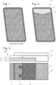
- FIG. 1 A molded part of a smartphone casing from the state of the art is shown.
- the molded part has a monocoque structure, which means it is single-shell and has only one wall material.
- the molded part was produced by pressing a prepreg in a mold. Prepregs are fabric mats soaked in a partially polymerized plastic.
- the partially polymerized plastic is epoxy resin or a vinyl ester. These are flexible when cold and can be laid in a mold. When pressed hot in a mold, the connecting plastic polymerizes, so that a solid mold is formed with a generally thin wall.
- a molded part 100 according to the invention for use in a smartphone or a tablet computer is shown.
- This molded part 100 consists of two materials.
- the majority of the molded part consists of carbon fiber reinforced plastic 101, which has been produced in a known manner by pressing a prepreg with epoxy resin, with melamine resin or with a vinyl ester resin.
- Thermoplastic materials are also used, with the individual carbon fibers being coated with a thermoplastic material.
- the carbon fiber reinforced molded part is only formed when the fabric is pressed in a mold under heat, with the coatings of neighboring carbon fibers fusing together.
- an antenna window 102 encompassing the entire wall thickness is introduced into the molded part 100.
- the antenna window 102 can consist of glass fiber reinforced epoxy resin, for example.
- the antenna window 102 is preferably accommodated at one end of an upright housing.
- the orientation of the fabric fibers of both plastics is the same.
- FIG 3 is a connection between the carbon fiber reinforced plastic 101 and the antenna window 102 in Figure 2 along the connecting edge between the carbon fiber reinforced plastic 101 and the antenna window 102.
- the carbon fiber reinforced plastic 101 in this embodiment consists of three layers A, B and C, which are equipped with carbon fiber fabric of a different bidirectional mesh density.
- the different layers A, B and C are connected to one another via a thermoplastic material TP.
- the innermost layer A consists, for example, of a carbon fiber reinforced plastic with a carbon fiber fabric with 12,000 carbon fibers per weave, so-called 12K fabric.
- the middle layer B consists, for example, of a carbon fiber reinforced plastic with a carbon fiber fabric with 3,000 carbon fibers, so-called 3K fabric
- the outermost layer C consists, for example, of a carbon fiber reinforced plastic with a carbon fiber fabric with 1,000 carbon fibers per weave, so-called 1K fabric.
- This thermoplastic material TP connecting the layers A and B serves as a connecting surface between the carbon fiber reinforced plastic and the glass fiber reinforced plastic of the antenna window 102.
- a glass fiber reinforced plastic rests on the tongue of the carbon fiber reinforced plastic 101 that is formed and has about half the wall thickness.
- This has individual undercuts 104 that protrude like pegs from the glass fiber reinforced plastic of the antenna window 102 and, when a prepreg is pressed, pour into corresponding and milled negative molds of the undercuts 104.
- the epoxy resin of the glass fiber reinforced plastic of the antenna window 102 bonds with the carbon fiber reinforced plastic 101 of the molded part.
- an overmolding 103 is provided, which is applied to the connecting edge of the two different materials by an injection molding system during pressing.
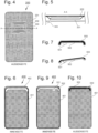
- an alternative embodiment of the molded part according to the invention is shown as a molded part 200.
- an antenna window 202 is embedded in the surface of the carbon fiber reinforced plastic 101.
- the layer that does not shield against electromagnetic radiation is only about half as thick as the wall thickness of the molded part 200.
- the antenna window 202 has an embedded antenna 300, which can also consist of carbon fibers.
- the ends of the individual fibers are passed through the fabric of the carbon fiber reinforced plastic 101 so that the ends can be connected to appropriate control electronics.
- Figure 5 a view of the section line AA in Figure 4 shown.
- the antenna 300 which can consist of individual carbon fibers, is embedded in the antenna window 202, with the antenna window 202 itself being embedded in the carbon fiber reinforced plastic 101.
- the embedding can be achieved by simply putting together a prepreg for pressing the carbon fiber reinforced plastic 101 and an antenna 300, with the plastic portion of the prepregs of the carbon fiber reinforced plastic 101 and the antenna 300 being placed around the individual carbon fibers in a correspondingly shaping manner when the put together prepregs are pressed.
- FIG. 6 a view of the inside of yet another embodiment of the molded part according to the invention is shown as a molded part 400.
- the molded part 400 has an antenna window 402, which itself is designed as a recess in the molded part 400.
- This recess serves to accommodate an insert antenna 500, which is firmly connected to the molded part 400 by overmolding.
- the insert antenna 500 is placed in the area of the antenna window 402 and connected to the antenna window 402 and the carbon fiber reinforced plastic 401 by overmolding in an injection mold.
- the insert antenna 500 protrudes from the molded part 400.
- the insert antenna 500 is shown in a top view. Visible from above is an electrical connection 501 and an electrical insulation body 502 for receiving the insert antenna 500 and for electrical insulation from the molded part 400.
- the same insert antenna 500 is shown in Figure 8 shown in perspective, the perspective view showing the shape of the insulating body 502.
- the insert antenna 500 shown here is shown together with the electrical insulating body 502.
- the insert antenna 500 is connected to the molded body 400 by overmolding with plastic in the mold, the electrical insulating body 502 being formed during the overmolding.
- FIG 8 the antenna is on Figure 7 shown in a perspective view.
- This insert antenna 500 is inserted with the narrower side into the recess of the antenna window 402 and connected to the molded part 400 by overmolding.
- the insulating body 502 is formed in the process.
- FIG 9 a view of the inside of the molded part 400 according to the invention Figure 6 with an insert antenna 500 molded in by overmolding.
- the electrical insulation body 502 insulates the insert antenna 500 from the molded part 400.
- the insert antenna 500 is shown in dashed lines because the electrical insulation body 502 covers the insert antenna 500.
- FIG 10 a view of the outside of the molded part 400 according to the invention Figure 6 with an insert antenna 500 molded in by overmolding.
- the electrical insulation body 502 insulates the insert antenna 500 from the molded part 400.
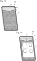
- FIG 11 a section through the molded part 100 according to the invention is shown in the area of a side wall 110.
- the carbon fiber reinforced plastic 101 is hot pressed in a mold.
- This border 112 can best be formed by a folded wall of the side wall 110 of the molded part, as shown in Figure 10 is shown.
- a border as 112' is injected as an overmold 105 into the edge of the molded part.
- the border 112' rests against the inner wall of the molded part and forms a border 105' for a display 111 in the area of the upper edge of the side wall 110, as shown in Figure 12
- the enclosure as 112' allows the top edge of the side wall 110 to be pressed into a mold without undercutting and can be easily demolded.
- a further embodiment of the molded part 600 according to the invention made of carbon fiber composite material is shown with an inserted antenna window 602 and a high-performance antenna 603.
- the high-performance antenna 603 can be made of metal and can receive signals for communication between the mobile terminal and a remote transmission tower.
- the material of the antenna window 602 accommodates and encloses the high-performance antenna 603 in a side wall of the molded part.
- the antenna window 602 serves for less powerful transmitting and receiving antennas, such as RFID antennas and antennas for near-field and medium-field communication.
- Figure 14 the molded part 100 from Figure 2 shown, wherein a circuit board 106 is arranged in the molded part 100 and is connected to an antenna 107.
- the antenna 107 is arranged in the area of the antenna window 102 so that the antenna 107 can transmit and receive without shielding.
Landscapes
- Chemical & Material Sciences (AREA)
- Engineering & Computer Science (AREA)
- Materials Engineering (AREA)
- Computer Networks & Wireless Communication (AREA)
- Manufacturing & Machinery (AREA)
- Inorganic Chemistry (AREA)
- Health & Medical Sciences (AREA)
- Chemical Kinetics & Catalysis (AREA)
- Medicinal Chemistry (AREA)
- Polymers & Plastics (AREA)
- Organic Chemistry (AREA)
- Microelectronics & Electronic Packaging (AREA)
- Signal Processing (AREA)
- Details Of Aerials (AREA)
- Casting Or Compression Moulding Of Plastics Or The Like (AREA)
Description
- Die Erfindung betrifft ein Formteil für ein mobiles Endgerät mit Sende und/oder Empfangsvorrichtung aus kohlenstofffaserverstärktem Kunststoff.
- Zur Herstellung von mobilen Endgeräten mit Sende und/oder Empfangsvorrichtung, wie Mobiltelefone oder Tablet-Computer, ist es bekannt, das Gehäuse des mobilen Endgerätes aus kohlenstofffaserverstärktem Kunststoff herzustellen. Der kohlenstofffaserverstärkte Kunststoff weist dabei ähnliche Festigkeitswerte auf wie aktuelle Formteile aus Aluminium/Magnesiumguss. Besonders an dem kohlenstofffaserverstärkten Kunststoff ist, dass dieser Schläge aufnehmen kann, wie es beim Herunterfallen eines Gerätes aus Handhöhe gelegentlich der Fall ist, wobei die aufgenommene kinetische Energie in dem Kohlenstofffaserverbund dissipiert wird und nicht an weitere Bauteile weitergleitet wird. Noch ein Vorteil der Gehäuse aus kohlenstofffaserverstärktem Kunststoff ist das geringe Gewicht. Aktuelle Mobiltelefone, die als sog. "Smartphones" bekannt sind, weisen nicht selten ein Gewicht von 200 g und mehr auf, was zum Tragen in einer Anzugjackeninnentasche schon zu einer unerwünschten Verzerrung des Anzugs führt. Das einseitige Gewicht des Smartphones wird auch als störend empfunden. Bei in naher Zukunft zu erwartenden Klapp-Smartphones, also Smartphones mit faltbarem Display, erhöht sich das Gewicht erheblich, weil jedes Formteil etwa das Gewicht eines heute einzelnen Smartphones erreicht.
- In der internationalen Patentanmeldung
WO 2017/202751 A1 werden Polycarbonat-Zusammensetzungen enthaltend Füllstoffe, eine Carbonsäure und deren Glycerol- oder Diglycerolester offenbart, wobei die Füllstoffe Kohlenstofffasern sind. Ein solcher Verbundwerkstoff wird zur Verwendung zum Aufbau einer Dünnwandanwendung wie sog. Ultrabooks oder Smartphones vorgestellt. Weiterhin offenbaren, das DokumentUS2015/0024811 A1 ein elektronisches Gerät das mit einem Abdeckelement aus faserverstärktem Kunststoff und das DokumentKR20140004336A - In der Regel werden Anwendungen von Kohlenstofffaserverbundwerkstoffen durch ihre mechanischen Eigenschaften und deren Gewicht charakterisiert. Ein eher modischer Nebeneffekt von Kohlenstofffaserverbundwerkstoffen ist die Sichtbarkeit des Kohlenstofffasergeleges oder des Kohlenstofffasergewebes.
- Der Einsatz von Kohlenstofffaserverbundwerkstoffen hat einen überraschenden Nebeneffekt. Durch die hohe elektrische Leitfähigkeit der Kohlenstofffasern hat eine Gehäusewand für ein Mobiltelefon, ein Tablet-Computer oder ein Smartphone eine Wirkung wie ein faradayscher Käfig. Der Effekt ist um so stärker ausgeprägt, in je mehr Richtungen die Kohlenstofffaserfilamente regelmäßig gelegt sind. Es gibt unidirektionale
- Kohlenstofffaserverbundwerkstoffe, die häufig mit UD-Verbund bezeichnet werden. Bei unidirektionalen Gelegen ist die Wirkung als faradayscher Käfig weniger stark ausgeprägt und die Abschirmung ist stark abhängig von der Gelegerichtung im Verhältnis zur Ausrichtung der Antenne innerhalb des mobilen Endgerätes. Weitere Einflussfaktoren sind die Frequenz der elektromagnetischen Strahlung und auch die Ausbreitung der elektromagnetischen Strahlung als Dipolantenne. Schon bei einem bidirektionalen Gewebe oder einem mehrlagigen Gelegen mit unterschiedlichen Richtungen der Filamente nimmt die Wirkung als faradayscher Käfig stark zu. Bei Geweben mit wenigen Filamenten, etwa 1.000 pro Strang, ist die abschirmende Wirkung so stark, dass ein Sende- und Empfangsvorgang nicht mehr möglich ist. Gegenüber einem anderen Kunststoffverbundwerkstoff hat Kohlenstofffaserverbundwerkstoff zunächst den Vorteil, dass die elektromagnetische Strahlung aus dem Mobiltelefon stark abgeschirmt wird. Die Abschirmleistung oder die Dämpfung der elektromagnetischen Strahlung ist vergleichbar mit der Dämpfung eines Gehäuses aus Aluminium/und/oder Magnesium.
- Um eine Sende- und Empfangsantenne in einem mobilen Endgerät zu betreiben, ist es bei Aluminium und/oder Magnesiumgehäusen bekannt, an eine Kante des Gehäuses vom Rest des Gehäuses galvanisch zu trennen. Die galvanisch abgetrennte Kante wird als Antenne für die Sende- und Empfangssignale des mobilen Endgerätes genutzt. Solche galvanischen Trennungen einer Kante eines mobilen Endgerätes sind äußerlich an scheinbaren Designstreifen erkennbar. Tatsächlich aber sind die Streifen aus Kunststoff oder Glas, um die galvanische Trennung zur Verfügung zu stellen.
- Ein vergleichbarer Aufbau eines Gehäuses aus kohlenstoffverstärktem Kunststoff ist nicht möglich.
- Aufgabe der Erfindung ist es daher, ein Formteil für mobile Geräte aus kohlenstofffaserverstärktem Kunststoff zur Verfügung zu stellen, welches einen Betrieb einer Sende- und Empfangsantenne innerhalb des mobilen Gerätes ermöglicht. Die erfindungsgemäße Aufgabe wird dadurch gelöst, dass ein Antennenfenster als Auslassung ausgebildet ist, in das eine Einlegeantenne eingesetzt ist, welche über einen elektrischen Isolationskörper mit dem Formteil verbunden ist, wobei die Einlegeantenne aus dem Formteil herausragt. Weitere vorteilhafte Ausgestaltungen sind in den Unteransprüchen zu Anspruch 1 angegeben.
- Nach dem Gedanken der Erfindung ist es vorgesehen, anders als es bei bekannten Formteilen für sendende, mobile Endgeräte bekannt ist, ein Antennenfenster in das Formteil einzubringen. Das Formteil besteht somit aus mindestens zwei verschiedenen Werkstoffen, wobei in vorteilhafter Weise der Werkstoff des Antennenfensters ebenso ein Faserverbundwerkstoff ist. Faserverstärkte Kunststoffe haben nämlich eine ausgeprägte Anisotropie in Bezug auf die Bruchfortpflanzung innerhalb ihres Gefüges. Um zu vermeiden, dass sich bei einem mechanischen Schlag auf das Gehäuse des mobilen Endgerätes, beispielsweise durch Herunterfallen, eine mechanische Stoßwelle an der Verbindung zwischen den unterschiedlichen Werkstoffen durch einen abrupten Wechsel der mechanischen Eigenschaften, wie örtlicher Elastizitätsmodul oder Schubmodul, so aufschaukelt, dass an der Verbindungslinie zwischen den unterschiedlichen Werkstoffen bevorzugt ein Riss entsteht, kann vorgesehen sein, dass das Antennenfenster aus glasfaserverstärktem Kunststoff besteht. Die Glasfasern können in identischer Richtung wie die Kohlenstofffasern verlegt oder mit dem gleichen Muster gewoben sein. Zwar sind die mechanischen Eigenschaften zwischen kohlenstofffaserverstärktem Kunststoff und glasfaserverstärktem Kunststoff unterschiedlich, aber die Anisotropie der lokalen mechanischen Eigenschaften der verschiedenen faserverstärkten Werkstoffe ist vergleichbar. Eine mechanische Stoßwelle breitet sich beim Übergang von dem einen Werkstoff zu dem zweiten Werkstoff gleichmäßiger aus. Ist das als Antennenfenster Auslassung ausgebildet, in das eine Einlegeantenne eingesetzt ist, so bildet die Einlegeantenne den zweiten Werkstoff des Antennenfensters aus.
- Um die elektromagnetische Dämpfung des Werkstoffes im Bereich des kohlenstofffaserverstärkten Kunststoffes zu erhöhen, und gleichzeitig um die Isotropie der mechanischen Stoßwellenausbreitung zu vergleichmäßigen, kann vorgesehen sein, dass der kohlenstofffaserverstärkte Kunststoff als mehraxiales Carbongewebe ausgeführt ist. Dem gegenüber kann das Antennenfenster zur Anpassung der Stoßwellenausbreitung und aus glasfaserverstärktem Kunststoff bestehen.
- Um die Stabilität im Bereich des Übergangs von kohlenstofffaserverstärktem Kunststoff und dem Antennenfenster zu erhöhen und eine Bruchneigung entlang der Verbindungslinie bei einem Schlag zu verringern, kann vorgesehen sein, dass die Verbindung zwischen dem kohlenstofffaserverstärkten Kunststoff und dem Antennenfenster als Hinterschneidung ausgebildet ist, wobei eine Negativform der Hinterschneidung in dem kohlenstofffaserverstärkten Kunststoff mit einer Positivform der Hinterschneidung am Antennenfenster korrespondiert, und wobei die Verbindung zwischen dem kohlenstofffaserverstärkten Kunststoff und dem Antennenfenster auf mindestens einer Seite mit einer Überspritzung überdeckt ist.
- Durch die Hinterschneidung greifen die verschiedenen Werkstoffe fest ineinander. Die Überspritzung, die im Spritzgießverfahren auf das Formteil aufgebracht werden kann, sichert die formschlüssige Verbindung der Positivform und der Negativform der Hinterschneidung vor einem lateralen Herausbrechen.
- Für eine weitere Stabilisierung der Verbindung zwischen dem kohlenstofffaserverstärkten Kunststoff und dem Antennenfenster kann vorgesehen sein, dass die Verbindung zwischen dem kohlenstofffaserverstärkten Kunststoff und dem Antennenfenster als Überlappung ausgebildet ist. Dazu kann der kohlenstofffaserverstärkte Kunststoff durch Fräsen auf etwa die Hälfte seiner Wandstärke reduziert sein. Das Antennenfenster kann durch Auflegen eines Prepregs und Pressen bei Hitze oder durch Auflegen eines thermoplastischen und glasfaserverstärkten Kunststoffes auf die abgefräste Fläche ausgebildet werden.
- Als Alternative zu einem für elektromagnetische Strahlung durchlässigen Fensters durch die gesamte Wandung kann auch vorgesehen sein, dass in einer Wand des Formteils ein Antennenfenster eingearbeitet ist, dass nur bis etwa zur Hälfte der Wandstärke reicht. Um das Antennenfenster zu nutzen, kann in dem Fenster eine Antenne eingearbeitet sein, welche eine elektrische Verbindung durch die kohlenstofffaserverstärkte Wand hat, um die Antenne mit innerhalb des Formteils angeordneter Elektronik zu verbinden.
- In besonderer Ausgestaltung der Erfindung kann vorgesehen sein, dass das Antennenfenster in die Oberfläche des Formteils aus kohlenstofffaserverstärktem Kunststoff eingebettet ist, wobei innerhalb des Antennenfensters eine Spulenantenne aus Kohlenstoffasern vorhanden ist. Kohlenstoffasern haben eine spezifische elektrische Leitfähigkeit, die mit metallischer elektrischer Leitfähigkeit vergleichbar ist und gegebenenfalls ist die Leitfähigkeit von Kohlenstofffasern noch höher. Kohlenstofffasern werden in der Regel mit thermoplastischem Kunststoff ummantelt, um sie beim Verpressen unter Hitze mit dem sie verbindenden Kunststoff zu verkleben. Diese Ummantelung führt zu einer guten elektrischen Isolierung der einzelnen Kohlenstofffasern. Werden nun in dem eingebetteten Antennenfenster die Kohlenstofffasern wie eine Spulenantenne gelegt, und werden die Enden der Kohlenstofffasern durch das Gewebe oder Gelege der Kohlenstofffasern zum Verstärken des Kunststoffes geführt, so kann die organische Kohlenstoffantenne wie eine metallische Antenne verwendet werden. Die Nutzung einer organischen Kohlenstofffaserantenne hat den weiteren Vorteil, dass die organische Hülle vollkommen transparent ist für Röntgenstrahlung. Mobiltelefone, Smartphones, Tablet-Computer können so bei einer Routinekontrolle am Flughafen oder in anderen Sicherheitsbereichen besser durchleuchtet werden. Zum Aufbau des Formteils kann vorgesehen sein, dass das Formteil ein mehraxiales Carbongewebe (Gewebe aus Kohlenstofffasern) aufweist, in welches eine Spule als Spulenantenne aus Kohlenstofffasern eingelegt ist, wobei die Enden der Kohlenstofffasern der Spulenantenne durch das mehraxiale Carbongewebe hindurchgeführt sind. Das mehrlagige Carbongewebe schirmt die innerhalb des Formteils vorhandene Elektronik gegenüber der Sendeleistung der Antenne ab.
- In weiterer, alternativer Ausgestaltung des Formteils kann vorgesehen sein, dass im Bereich des Antennenfensters eine Einlegeantenne angeordnet ist, welche durch Überspritzen des kohlenstofffaserverstärkten Kunststoffes mit dem Formteil verbunden ist. Es ist nach dieser optionalen Ausgestaltung der Erfindung also vorgesehen, dass das Formteil mit einer Einlegeantenne ausgestattet ist, wobei die Einlegeantenne durch das Antennenfenster senden und empfangen kann.
- Die Dichte der Kohlenstofffasern und die Dichte der Maschen des Gewebes haben einen Einfluss auf die abschirmende Wirkung gegenüber elektromagnetischer Strahlung im Bereich von 800 MHz bis 4 GHz. Als vorteilhafte Gewebemaschen haben sich solche Gewebe als vorteilhaft herausgestellt, die mit 1.000 Fasern pro Strang, mit 3.000 Fasern pro Strang und 12.000 Fasern pro Strang gewebt sind. Solche Kohlenstofffasergewebe werden im Handel als 1K (1.000 Fasern/Filamente), 3K (3.000 Fasern/Filamente) und 12K-Gewebe (12.000 Fasern/Filamente) angeboten. Das Formteil kann hergestellt werden durch Verpressen eines Prepregs in einer Form oder aus heißem Verformen eines thermoplastischen und kohlenstofffaserverstärkten Kunststoffes oder aus Fasern, die bereits mit einem thermoplastischen Kunststoff ummantelt sind.
- In einer speziellen Ausgestaltung des erfindungsgemäßen Formteils kann vorgesehen sein, dass eine Seitenwand des Formteils eine metallische Hochleistungsantenne umfasst, wobei das Material des Antennenfensters die metallische Hochleistungsantenne galvanisch von dem kohlenstofffaserverstärkten Kunststoff trennt.
- Die Erfindung wird anhand der folgenden Figuren näher erläutert. Es zeigt:
- Fig. 1
- ein Formteil eines Smartphones aus dem STAND DER TECHNIK, hier als einteilige Form einer Schale,
- Fig. 2
- ein erfindungsgemäßes Formteil aus Kohlenstofffaserverbundwerkstoff mit einem eingelassenen Antennenfenster,
- Fig. 3
- eine Darstellung einer Verbindung zwischen Kohlenstofffaserverbundwerkstoff und einem eingesetzten Antennenfenster,
- Fig. 4
- ein erfindungsgemäßes Formteil mit einem eingebettetem Antennenfenster und einer Kohlenstofffaserantenne,
- Fig. 5
- einen Ausschnitt einer vergrößerten Ansicht auf die Schnittlinie A-A in
Figur 4 , - Fig. 6
- eine Ansicht auf die Innenseite einer weiteren alternativen Ausgestaltung eines erfindungsgemäßen Formteils mit einem ausgelassenen Antennenfenster,
- Fig. 7
- eine Einlegeantenne,
- Fig. 8
- die Einlegeantenne aus
Figur 7 in einer perspektivischen Ansicht, - Fig. 9
- eine Ansicht auf die Innenseite das erfindungsgemäße Formteil aus
Figur 6 mit einer durch Überspritzung eingeformten Einlegeantenne, - Fig. 10
- eine Ansicht auf die Außenseite das erfindungsgemäße Formteil aus
Figur 6 mit einer durch Überspritzung eingeformten Einlegeantenne, - Fig. 11
- ein Detail der Seitenwand des erfindungsgemäßen Formteils mit einer Hinterschneidung,
- Fig. 12
- das Detail aus
Figur 10 , in welcher die Hinterschneidung durch eine Überspritzung vermieden worden ist, - Fig. 13
- eine weitere Ausführungsform des erfindungsgemäßen Formteils aus Kohlenstofffaserverbundwerkstoff mit einem eingesetzten Antennenfenster und einer Hochleistungsantenne.
- In
Figur 1 ist ein Formteil eines Gehäuses eines Smartphones aus dem Stand der Technik abgebildet. Das Formteil hat ein Monocoque-Aufbau, das bedeutet, es ist einschalig und weist nur ein einziges Wandmaterial auf. Das Formteil ist durch bekanntes Pressen eines Prepregs in einer Form hergestellt worden. Prepregs sind mit einem teilpolymerisierten Kunststoff getränkte Gewebematten. Der teilpolymerisierte Kunststoff ist dabei Epoxidharz oder ein Vinylester. Diese sind im kalten Zustand flexibel und können in einer Form vergelegt werden. Beim heißen Verpressen in einer Form polymerisiert der verbindende Kunststoff, so dass sich eine feste Form mit einer in der Regel dünnen Wand bildet. - In
Figur 2 ist ein erfindungsgemäßes Formteil 100 zur Verwendung für ein Smartphone oder ein Tablet-Computer gezeigt. Dieses Formteil 100 besteht aus zwei Werkstoffen. Der überwiegende Anteil des Formteils besteht aus kohlenstofffaserverstärktem Kunststoff 101, das in bekannter Weise durch Verpressen eines Prepregs mit Epoxidharz, mit Melaminharz oder mit einem Vinylesterharz hergestellt worden ist. Auch thermoplastische Werkstoffe kommen zum Einsatz, wobei die einzelnen Kohlenstofffasern mit einem thermoplastischen Werkstoff ummantelt sind. Erst beim Pressen des Gewebes in einer Form unter Hitze bildet sich das kohlenstofffaserverstärkte Formteil, wobei die Ummantelungen benachbarter Kohlenstofffasern miteinander verschmelzen. In dieser erfindungsgemäßen Ausgestaltung des Formteils ist vorgesehen, dass ein die gesamte Wandstärke umfassendes Antennenfenster 102 in das Formteil 100 eingebracht ist. Dabei kann das Antennenfenster 102 beispielsweise aus glasfaserverstärktem Epoxidharz bestehen. Das Antennenfenster 102 ist vorzugsweise an einem Ende eines Hochkantgehäuses untergebracht. An dieser Stelle befindet ich in bekannten Smartphones, Mobiltelefonen und/oder Tablet-Computern eine Antenne zum Senden und Empfangen von Radiostrahlung zur Kommunikation mit entfernten Sende- und Empfangsmasten. Um die lokalen mechanischen Eigenschaften des kohlenstofffaserverstärkten Kunststoffes 101 und des hier glasfaserverstärkten Epoxidharzes des Antennenfensters 102 aneinander anzupassen, kann vorgesehen sein, dass die Ausrichtung der Gewebefasern beider Kunststoffe gleichgerichtet ist. - In
Figur 3 ist eine Verbindung zwischen dem kohlenstofffaserverstärkten Kunststoff 101 und dem Antennenfenster 102 inFigur 2 entlang der Verbindungskante zwischen dem kohlenstofffaserverstärktem Kunststoff 101 und dem Antennenfenster 102 gezeigt. Der kohlenstofffaserverstärkte Kunststoff 101 besteht in dieser Ausführungsform aus drei Lagen A, B und C, die mit Kohlenstofffasergewebe einer unterschiedlichen bidirektionalen Maschendichte ausgestattet sind. Die unterschiedlichen Lagen A, B und C sind über einen thermoplastischen Werkstoff TP miteinander verbunden. Dabei besteht die innerste Lage A beispielsweise aus einem kohlenstofffaserverstärkten Kunststoff mit einem Kohlenstofffasergewebe mit 12.000 Kohlenstofffasern pro Webstrang, sogenanntes 12K-Gewebe. Die mittlere Schicht B besteht beispielsweise aus einem kohlenstofffaserverstärkten Kunststoff mit einem Kohlenstofffasergewebe mit 3.000 Kohlenstofffasern, sogenanntes 3K-Gewebe und die äußerste Schicht C besteht beispielsweise aus einem kohlenstofffaserverstärkten Kunststoff mit einem Kohlenstofffasergewebe mit 1.000 Kohlenstofffasern pro Webstrang, sogenanntes 1K-Gewebe. Zum Verbinden des kohlenstofffaserverstärkten Kunststoffes 101 mit dem Antennenfenster 102, das hier in diesem Beispiel aus einem glasfaserverstärkten Kunststoff besteht, wird das Formteil im Bereich der Kante des kohlenstofffaserverstärkten Kunststoffs 101 soweit abgetragen, dass die Schichtdicke nur noch etwa die Hälfte der gesamten Wandstärke des Formteils 100 entspricht, wobei jedoch ein Teil des die Lagen A und B verbindenden thermoplastischen Werkstoffes TP stehen bliebt. Dieser, die Lagen A und B verbindende thermoplastische Werkstoff TP dient als Verbindungsfläche zwischen dem kohlenstofffaserverstärkten Kunststoff und dem glasfaserverstärkten Kunststoff des Antennenfensters 102. Auf der sich ausbildende Zunge des kohlenstofffaserverstärkten Kunststoffs 101 mit etwa der halben Wandstärke liegt in diesem Beispiel ein glasfaserverstärkter Kunststoff auf. Dieser weist einzelne Hinterschneidungen 104 auf, die wie Zapfen aus dem glasfaserverstärkten Kunststoff des Antennenfensters 102 herausragen und sich beim Pressen eines Prepregs in korrespondierende und eingefräste Negativformen der Hinterschneidungen 104 ergießen. Beim Pressen des Prepregs des glasfaserverstärkten Kunststoffes für das Antennenfenster 102 verbindet sich das Epoxidharz des glasfaserverstärkten Kunststoffes das Antennenfensters 102 mit dem kohlenstofffaserverstärkten Kunststoff 101 des Formteils. Um die Hinterschneidungen davor zu bewahren aus den Negativformen herauszubrechen, ist eine Überspritzung 103 vorgesehen, die beim Pressen durch ein Spritzgusssystem auf die Verbindungskante der beiden unterschiedlichen Materialien aufgebracht wird. - In
Figur 4 ist eine alternative Ausgestaltung des erfindungsgemäßen Formteils als Formteil 200 gezeigt. In diesem Formteil ist ein Antennenfenster 202 in die Oberfläche des kohlenstofffaserverstärkten Kunststoffes 101 eingebettet. Dabei ist die elektromagnetische Strahlung nicht abschirmende Schicht nur etwa halb so dick, wie die Wanddicke des Formteils 200. Das Antennenfenster 202 hat in diesem Fall eine eingebettete Antenne 300, die auch aus Kohlenstofffasern bestehen kann. Im Fall der Kohlenstofffaserantenne sind die Enden der einzelnen Fasern durch das Gewebe des kohlenstofffaserverstärkten Kunststoffes 101 hindurchgeführt, so dass die Enden mit einer entsprechenden Ansteuerelektronik verbunden werden können. Um die Lage der eingebetteten Antenne 300 zu verdeutlichen, ist inFigur 5 eine Ansicht auf die Schnittlinie A-A inFigur 4 gezeigt. Die Antenne 300, die aus einzelnen Kohlenstofffasern bestehen kann, ist in das Antennenfenster 202 eingebettet, wobei das Antennenfenster 202 selbst in den kohlenstofffaserverstärkten Kunststoff 101 eingebettet ist. Die Einbettung kann durch einfaches Zusammenlegen eines Prepregs zum Pressen des kohlenstofffaserverstärkten Kunststoffes 101 und einer Antenne 300 erreicht werden, wobei beim sich beim Pressen der zusammengelegten Prepregs der Kunststoffanteil der Prepregs des kohlenstofffaserverstärkten Kunststoffes 101 und der Antenne 300 entsprechend formgebend um die einzelnen Kohlenstofffasern legt. - In
Figur 6 ist eine Ansicht auf die Innenseite einer noch weiteren Ausgestaltung des erfindungsgemäßen Formteils als Formteil 400 gezeigt. Das Formteil 400 weist ein Antennenfenster 402 auf, das selbst als Ausnehmung in das Formteil 400 ausgebildet ist. Diese Ausnehmung dient zur Aufnahme einer Einlegeantenne 500, die durch Überspritzen fest mit dem Formteil 400 verbunden ist. Dazu wird die Einlegeantenne 500 im Bereich des Antennenfensters 402 platziert und durch Überspritzen in einer Spritzform mit dem Antennenfenster 402 und dem kohlenstofffaserverstärkten Kunststoff 401 verbunden. Dabei ragt die Einlegeantenne 500 aus dem Formteil 400 heraus. - In
Figur 7 ist die Einlegeantenne 500 in einer Aufsicht dargestellt. Von oben erkennbar ist ein elektrischer Anschluss 501 und ein elektrischer Isolationskörper 502 zur Aufnahme der Einlegeantenne 500 und zur elektrischen Isolation gegenüber dem Formteil 400. Die gleiche Einlegeantenne 500 ist inFigur 8 perspektivisch dargestellt, wobei aus der perspektivischen Ansicht die auftragende Form des Isolationskörpers 502 hervorgeht. Die hier gezeigte Einlegeantenne 500 ist zusammen mit dem elektrischen Isolationskörper 502 gezeigt. Tatsächlich wird die Einlegeantenne 500 durch Überspritzen mit Kunststoff in der Form mit dem Formkörper 400 verbunden, wobei sich beim Überspritzen der elektrische Isolationskörper 502 ausbildet. - In
Figur 8 ist die Einlegeantenne aufFigur 7 in einer perspektivischen Ansicht gezeigt. Diese Einlegeantenne 500 wird mit der schmaleren Seite in die Ausnehmung des Antennenfenster 402 eingelegt und mit dem Formteil 400 durch Überspritzen verbunden. Dabei bildet sich der Isolationskörper 502 aus. - In
Figur 9 eine Ansicht auf die Innenseite das erfindungsgemäße Formteils 400 ausFigur 6 mit einer durch Überspritzung eingeformten Einlegeantenne 500 gezeigt. Der elektrische Isolationskörper 502 isoliert die Einlegeantenne 500 gegenüber dem Formteil 400. In dieser Ansicht ist die Einlegeantenne 500 gestrichelt gezeichnet, weil der elektrische Isolationskörper 502 die Einlegeantenne 500 verdeckt. - In
Figur 10 eine Ansicht auf die Außenseite das erfindungsgemäße Formteils 400 ausFigur 6 mit einer durch Überspritzung eingeformten Einlegeantenne 500 gezeigt. Der elektrische Isolationskörper 502 isoliert die Einlegeantenne 500 gegenüber dem Formteil 400. - In
Figur 11 ist ein Schnitt durch das erfindungsgemäße Formteil 100 im Bereich einer Seitenwand 110 gezeigt. Der kohlenstofffaserverstärkte Kunststoff 101 wird in einer Form heiß gepresst. Um die Oberfläche des Formteils mit einem Display 111 bündig zu verbinden, ist es notwendig, dass das Display in einer Einfassung 112 liegt. Diese Einfassung 112 kann am besten durch eine umgelegte Wandung der Seitenwand 110 des Formteils gebildet werden, wie es inFigur 10 gezeigt ist. - Um zu vermeiden, dass sich eine Hinterschneidung in der Form bildet, die eine komplexe Form zum Entformen erfordert, dann eine Einfassung als 112' als Überspritzung 105 in die Kante des Formteils eingespritzt werden. Die Einfassung 112' lehnt sich an die innere Wand des Formteils an und bildet im Bereich der Wandoberkante der Seitenwand 110 eine Einfassung 105' für ein Display 111, wie es in
Figur 12 gezeigt ist. Die Einfassung als 112' ermöglicht, dass die Wandoberkante der Seitenwand 110 ohne Hinterschneidung in einer Form gepresst werde und leicht entformt werden kann. - In
Figur 13 ist eine weitere Ausführungsform des erfindungsgemäßen Formteils 600 aus Kohlenstofffaserverbundwerkstoff mit einem eingesetzten Antennenfenster 602 und einer Hochleistungsantenne 603 dargestellt. Die Hochleistungsantenne 603 kann metallisch aufgebaut sein und Signale zur Kommunikation des mobilen Endgerätes zu einem entfernten Sendemast übernehmen. Um die Hochleistungsantenne 603 galvanisch von dem elektrisch leitfähigen, kohlenstofffaserverstärkten Kunststoff zu trennen, ist vorgesehen, dass das Material des Antennenfensters 602 die Hochleistungsantenne 603 in einer Seitenwand des Formteils aufnimmt und einfasst. Das Antennenfenster 602 dienst in diesem Beispiel für weniger leistungsstarke Sende- und Empfangsantennen, wie beispielsweise RFID-Antennen und Antennen für die Nahfeld- und Mittelfeldkommunikation. - In
Figur 14 das Formteil 100 ausFigur 2 dargestellt, wobei in dem Formteil 100 eine Platine 106 angeordnet ist, die mit einer Antenne 107 verbunden ist. Die Antenne 107 ist im Bereich des Antennenfensters 102 angeordnet, so dass die Antenne 107 ohne Abschirmung senden und empfangen kann. -
100 Formteil 400 Formteil 101 kohlenstofffaserverstärkter Kunststoff 401 kohlenstofffaserverstärkter Kunststoff 102 Antennenfenster 402 Antennenfenster 103 Überspritzung 404 elektrischer Anschluss 104 Hinterschneidung 105 Überspritzung 500 Einlegeantenne 105' Einfassung 501 elektrischer Anschluss 106 Platine 502 elektrischer Isolationskörper 107 Antenne 110 Seitenwand 600 Formteil 111 Display 601 kohlenstofffaserverstärkter Kunststoff 112 Einfassung 112' Einfassung 602 Antennenfenster 603 Hochleistungsantenne 200 Formteil 604 Seitenwand 201 kohlenstofffaserverstärkter Kunststoff A Schicht 202 Antennenfenster TP thermoplastischer Werkstoff 300 Spulenantenne B Schicht C Schicht
Claims (11)
- Formteil (400) für ein mobiles Endgerät mit Sende und/oder Empfangsvorrichtung aus kohlenstofffaserverstärktem Kunststoff (101, 401) dadurch gekennzeichnet, dassein Antennenfenster (402) als Auslassung ausgebildet ist, in das eine Einlegeantenne (500) eingesetzt ist, welche über einen elektrischen Isolationskörper (502) mit dem Formteil (400) verbunden ist,wobei die Einlegeantenne (500) aus dem Formteil 400 herausragt.
- Formteil nach Anspruch 1,
dadurch gekennzeichnet, dass
der kohlenstofffaserverstärkte Kunststoff (101) als mehraxiales Carbongewebe ausgeführt ist. - Formteil nach Anspruch 1 oder 2,
dadurch gekennzeichnet, dass
das Antennenfenster (102) aus glasfaserverstärktem Kunststoff besteht. - Formteil nach einem der Ansprüche 1 bis 3,
dadurch gekennzeichnet, dassdie Verbindung zwischen dem kohlenstofffaserverstärkten Kunststoff (101) und dem Antennenfenster (102) als Hinterschneidung (104) ausgebildet ist,wobei eine Negativform der Hinterschneidung (104) in dem kohlenstofffaserverstärkten Kunststoff (101) mit einer Positivform am Antennenfenster (102) korrespondiert, und wobeidie Verbindung zwischen dem kohlenstofffaserverstärkten Kunststoff (101) und dem Antennenfenster (102) auf mindestens einer Seite mit einer Überspritzung (103) überdeckt ist. - Formteil nach Anspruch 4,
dadurch gekennzeichnet, dass
die Verbindung zwischen dem kohlenstofffaserverstärkten Kunststoff (101) und dem Antennenfenster (102) als Überlappung ausgebildet ist. - Formteil nach Anspruch 1,
dadurch gekennzeichnet, dass
das Antennenfenster (202) in die Oberfläche des Formteils aus kohlenstofffaserverstärktem Kunststoff (101) eingebettet ist, wobei innerhalb des Antennenfensters (102) eine Spulenantenne (300) aus Kohlenstoffasern vorhanden ist. - Formteil nach Anspruch 6,
dadurch gekennzeichnet, dass
das Formteil (100) ein mehraxiales Carbongewebe aufweist, in welches eine Spule aus Spulenantenne (300) aus Kohlenstoffasern eingelegt ist, wobei die Enden der Kohlenstoffasern der Spulenantenne (300) aus Kohlenstoffasern durch das mehraxiale Carbongewebe hindurchgeführt sind. - Formteil nach einem der Ansprüche 1 bis 7,
dadurch gekennzeichnet, dass
im Bereich des Antennenfensters (402) eine Einlegeantenne (500) in einer Ausnehmung des Formteils angeordnet ist, welche durch Überspritzen des kohlenstofffaserverstärkten Kunststoffes (401) mit dem Formteil (400) verbunden ist. - Formteil nach einem der Ansprüche 1 bis 8,
dadurch gekennzeichnet, dass
der kohlenstofffaserverstärkte Kunststoff (101) aus mehr als einer Lage (A, B, C) besteht, bevorzugt zwischen 2 und 10 Lagen besteht, besonders bevorzugt aus drei Lagen besteht, in welchem die Kohlenstofffasern mit einer Leinwandbindung mit 1.000, 3.000 oder 12.000 Filamenten pro Bündel miteinander verwebt sind und benachbarte Lagen unterschiedliche Anzahl an Filamenten pro Bündel aufweisen. - Formteil nach einem der Ansprüche 1 bis 8,
dadurch gekennzeichnet, dass
kohlenstofffaserverstärkte Kunststoff (101) aus einem Prepreg oder aus mit thermoplastischem Kunststoff ummantelten Filamenten hergestellt ist. - Formteil nach einem der Ansprüche 1 bis 8,
dadurch gekennzeichnet, dass
eine Seitenwand (604) des Formteils (600) eine metallische Hochleistungsantenne (603) umfasst, wobei das Material des Antennenfensters (602) die metallische Hochleistungsantenne (603) galvanisch von dem kohlenstofffaserverstärkten Kunststoff (601) trennt.
Applications Claiming Priority (2)
| Application Number | Priority Date | Filing Date | Title |
|---|---|---|---|
| DE102020118348.8A DE102020118348B4 (de) | 2020-07-11 | 2020-07-11 | Formteil für ein mobiles Endgerät mit Sende und/oder Empfangsvorrichtung aus kohlenstofffaserverstärktem Kunststoff |
| PCT/IB2021/056173 WO2022013693A1 (de) | 2020-07-11 | 2021-07-09 | Formteil für ein mobiles endgerät mit sende und/oder empfangsvorrichtung aus kohlenstofffaserverstärktem kunststoff |
Publications (4)
| Publication Number | Publication Date |
|---|---|
| EP4179719A1 EP4179719A1 (de) | 2023-05-17 |
| EP4179719B1 true EP4179719B1 (de) | 2024-09-18 |
| EP4179719C0 EP4179719C0 (de) | 2024-09-18 |
| EP4179719B8 EP4179719B8 (de) | 2024-12-11 |
Family
ID=77168310
Family Applications (1)
| Application Number | Title | Priority Date | Filing Date |
|---|---|---|---|
| EP21749300.6A Active EP4179719B8 (de) | 2020-07-11 | 2021-07-09 | Formteil für ein mobiles endgerät mit sende und/oder empfangsvorrichtung aus kohlenstofffaserverstärktem kunststoff |
Country Status (4)
| Country | Link |
|---|---|
| US (1) | US20230318653A1 (de) |
| EP (1) | EP4179719B8 (de) |
| DE (1) | DE102020118348B4 (de) |
| WO (1) | WO2022013693A1 (de) |
Families Citing this family (3)
| Publication number | Priority date | Publication date | Assignee | Title |
|---|---|---|---|---|
| US20220110231A1 (en) * | 2020-10-06 | 2022-04-07 | Pranav Bollapragada | Electromagnetic field radiation and anti-microbial protection case assembly for electronic devices |
| CN118377348A (zh) * | 2023-01-13 | 2024-07-23 | 神基科技股份有限公司 | 防护套及可携式电子装置 |
| US20250251764A1 (en) * | 2024-02-02 | 2025-08-07 | Joseph Leo Wesley | Cooling case for electronic device |
Family Cites Families (14)
| Publication number | Priority date | Publication date | Assignee | Title |
|---|---|---|---|---|
| CN101437057B (zh) | 2007-11-16 | 2012-11-07 | 华硕电脑股份有限公司 | 移动通讯装置及其壳体结构 |
| DE202011110183U1 (de) | 2011-09-24 | 2013-03-28 | Oechsler Aktiengesellschaft | Mit einer Antenne ausgestattete Gehäuseschale fürinsbesondere ein mobiles Telekommunikationsgerät |
| CN103037642B (zh) | 2011-09-30 | 2017-08-25 | 深圳富泰宏精密工业有限公司 | 外壳的制造方法 |
| CN103891042B (zh) | 2011-10-19 | 2018-06-19 | 惠普发展公司,有限责任合伙企业 | 包括信号传递束和信号阻塞束的材料 |
| DE102011121034B4 (de) * | 2011-12-14 | 2013-11-07 | Oechsler Ag | Gehäuseschale, insbesondere eines tragbaren elektronischen Gerätes wie eines Kommunikationsgerätes, und Gerät mit derartiger Gehäuseschale |
| JPWO2013136398A1 (ja) | 2012-03-12 | 2015-07-30 | 日本電気株式会社 | 携帯端末装置 |
| KR20140004336A (ko) * | 2012-07-02 | 2014-01-13 | 엘지전자 주식회사 | 이동 단말기 및 이동 단말기 후면커버의 제조방법 |
| CN103935045A (zh) | 2013-01-21 | 2014-07-23 | 汉达精密电子(昆山)有限公司 | 碳纤维处理方法及其产品 |
| KR102066482B1 (ko) * | 2013-07-16 | 2020-01-15 | 삼성전자주식회사 | 섬유 강화 플라스틱 소재 및 그를 포함하는 전자 기기 |
| US9464360B2 (en) * | 2014-01-15 | 2016-10-11 | Htc Corporation | Electronic device and casing thereof |
| US9755682B2 (en) * | 2015-01-15 | 2017-09-05 | C. A. Byler | Cases having selectable RF shielding |
| EP3464440B1 (de) | 2016-05-24 | 2020-05-13 | Covestro Deutschland AG | Polycarbonat-zusammensetzungen enthaltend füllstoffe, eine carbonsäure und deren glycerol- oder diglycerolester |
| EP3478040A4 (de) | 2016-06-23 | 2020-02-26 | Toray Industries, Inc. | Gehäuse und verfahren zur herstellung eines gehäuses |
| US10630331B2 (en) * | 2016-07-29 | 2020-04-21 | Rowtan Technologies Llc | Devices for reflecting, deflecting, and/or absorbing electromagnetic radiation emitted from an electronic device and methods therefor |
-
2020
- 2020-07-11 DE DE102020118348.8A patent/DE102020118348B4/de active Active
-
2021
- 2021-07-09 EP EP21749300.6A patent/EP4179719B8/de active Active
- 2021-07-09 WO PCT/IB2021/056173 patent/WO2022013693A1/de not_active Ceased
- 2021-07-09 US US18/014,558 patent/US20230318653A1/en active Pending
Also Published As
| Publication number | Publication date |
|---|---|
| DE102020118348A1 (de) | 2022-01-13 |
| EP4179719B8 (de) | 2024-12-11 |
| DE102020118348B4 (de) | 2025-04-30 |
| US20230318653A1 (en) | 2023-10-05 |
| EP4179719A1 (de) | 2023-05-17 |
| EP4179719C0 (de) | 2024-09-18 |
| WO2022013693A1 (de) | 2022-01-20 |
Similar Documents
| Publication | Publication Date | Title |
|---|---|---|
| EP4179719B1 (de) | Formteil für ein mobiles endgerät mit sende und/oder empfangsvorrichtung aus kohlenstofffaserverstärktem kunststoff | |
| DE60318123T2 (de) | Millimeterwellen-Radar mit nebenkeulenabsorbierendem Radom | |
| DE102009055289B4 (de) | Antennenmuster-Rahmen und Verfahren zu dessen Herstellung | |
| DE60124196T2 (de) | Antennenanordnung in einer Mobilstation | |
| EP1745527B1 (de) | Antennenanordnung zur induktiven energieübertragung und verwendung der antennenanordnung | |
| DE3341468A1 (de) | Elektromagnetische abschirmung | |
| DE202012104339U1 (de) | Batteriegehäuseteil und Batteriegehäuse für eine Traktionsbatterie eines Elektrofahrzeugs | |
| DE102009046679A1 (de) | Gehäuse mit einer eingebetteten Antenne für ein Mobilfunkgerät, Verfahren zum Herstellen desselben und Mobilfunkgerät | |
| DE19528703A1 (de) | Antenne für das Senden oder Empfangen eines Hochfrequenzsignals, Sender und Empfänger zu einer Fernbedienung und Fernbedienungssystem für ein Kraftfahrzeug, in die sie eingebaut ist | |
| DE112017008496B4 (de) | Antennenvorrichtung | |
| DE212010000141U1 (de) | Form aus Verbundwerkstoff mit verbesserter Formoberfläche | |
| DE19506175A1 (de) | Antenne und Funktelephon, das dieselbe verwendet | |
| EP0854536A2 (de) | Faserverstärktes Kunststoff-Formteil mit integrierter Antenne | |
| EP4162342B1 (de) | Gehäuseteil aus kohlefaserverstärktem kunststoff für eine elektronische vorrichtung | |
| WO2012100859A1 (de) | Antenne für ein unterseeboot | |
| DE102010055206A1 (de) | Bordinformationssystem mit Mobilfunkantenne | |
| DE102020008085B4 (de) | Formteil für ein mobiles Endgerät mit Sende und/oder Empfangsvorrichtung aus kohlenstofffaserverstärktem Kunststoff | |
| DE102006018907A1 (de) | Drahtlostransceiver und Herstellungsverfahren hierfür | |
| DE102007008575B4 (de) | Antennenvorrichtung mit ionenimplantierter Resonanzstruktur | |
| DE102017216740A1 (de) | Leitender Kunststoffkörper, Fahrzeug-Erdungsstruktur und Verfahren zum Herstellen des leitenden Kunststoffkörpers | |
| DE202010014774U1 (de) | Gehäuse oder Gehäuseteil eines elektronischen Gerätes sowie elektronisches Gerät | |
| DE69602127T2 (de) | Selektivfunkrufempfänger | |
| DE102013114000A1 (de) | Verfahren zur Herstellung eines Türaußengriffs | |
| DE102009030402B4 (de) | Gehäuse für ein mobiles Kommunikationsendgerät sowie Verfahren zu dessen Herstellung | |
| EP2907945B1 (de) | Kommunikationseinrichtungen |
Legal Events
| Date | Code | Title | Description |
|---|---|---|---|
| STAA | Information on the status of an ep patent application or granted ep patent |
Free format text: STATUS: UNKNOWN |
|
| STAA | Information on the status of an ep patent application or granted ep patent |
Free format text: STATUS: THE INTERNATIONAL PUBLICATION HAS BEEN MADE |
|
| PUAI | Public reference made under article 153(3) epc to a published international application that has entered the european phase |
Free format text: ORIGINAL CODE: 0009012 |
|
| STAA | Information on the status of an ep patent application or granted ep patent |
Free format text: STATUS: REQUEST FOR EXAMINATION WAS MADE |
|
| 17P | Request for examination filed |
Effective date: 20230109 |
|
| AK | Designated contracting states |
Kind code of ref document: A1 Designated state(s): AL AT BE BG CH CY CZ DK EE ES FI FR GB GR HR HU IE IS IT LI LT LU LV MC MK MT NL NO PL PT RO RS SE SI SK SM TR |
|
| DAV | Request for validation of the european patent (deleted) | ||
| DAX | Request for extension of the european patent (deleted) | ||
| GRAP | Despatch of communication of intention to grant a patent |
Free format text: ORIGINAL CODE: EPIDOSNIGR1 |
|
| STAA | Information on the status of an ep patent application or granted ep patent |
Free format text: STATUS: GRANT OF PATENT IS INTENDED |
|
| INTG | Intention to grant announced |
Effective date: 20240402 |
|
| GRAS | Grant fee paid |
Free format text: ORIGINAL CODE: EPIDOSNIGR3 |
|
| GRAA | (expected) grant |
Free format text: ORIGINAL CODE: 0009210 |
|
| STAA | Information on the status of an ep patent application or granted ep patent |
Free format text: STATUS: THE PATENT HAS BEEN GRANTED |
|
| AK | Designated contracting states |
Kind code of ref document: B1 Designated state(s): AL AT BE BG CH CY CZ DK EE ES FI FR GB GR HR HU IE IS IT LI LT LU LV MC MK MT NL NO PL PT RO RS SE SI SK SM TR |
|
| REG | Reference to a national code |
Ref country code: GB Ref legal event code: FG4D Free format text: NOT ENGLISH |
|
| REG | Reference to a national code |
Ref country code: CH Ref legal event code: EP |
|
| REG | Reference to a national code |
Ref country code: IE Ref legal event code: FG4D Free format text: LANGUAGE OF EP DOCUMENT: GERMAN |
|
| U01 | Request for unitary effect filed |
Effective date: 20241010 |
|
| REG | Reference to a national code |
Ref country code: CH Ref legal event code: PK Free format text: BERICHTIGUNG B8 |
|
| RBV | Designated contracting states (corrected) |
Designated state(s): AL AT BE BG CH CY CZ DE DK EE ES FI FR GB GR HR HU IE IS IT LI LT LU LV MC MK MT NL NO PL PT RO RS SE SI SK SM TR |
|
| U07 | Unitary effect registered |
Designated state(s): AT BE BG DE DK EE FI FR IT LT LU LV MT NL PT RO SE SI Effective date: 20241107 |
|
| REG | Reference to a national code |
Ref country code: DE Ref legal event code: R096 Ref document number: 502021006015 Country of ref document: DE |
|
| PG25 | Lapsed in a contracting state [announced via postgrant information from national office to epo] |
Ref country code: NO Free format text: LAPSE BECAUSE OF FAILURE TO SUBMIT A TRANSLATION OF THE DESCRIPTION OR TO PAY THE FEE WITHIN THE PRESCRIBED TIME-LIMIT Effective date: 20241218 |
|
| PG25 | Lapsed in a contracting state [announced via postgrant information from national office to epo] |
Ref country code: GR Free format text: LAPSE BECAUSE OF FAILURE TO SUBMIT A TRANSLATION OF THE DESCRIPTION OR TO PAY THE FEE WITHIN THE PRESCRIBED TIME-LIMIT Effective date: 20241219 |
|
| PG25 | Lapsed in a contracting state [announced via postgrant information from national office to epo] |
Ref country code: HR Free format text: LAPSE BECAUSE OF FAILURE TO SUBMIT A TRANSLATION OF THE DESCRIPTION OR TO PAY THE FEE WITHIN THE PRESCRIBED TIME-LIMIT Effective date: 20240918 |
|
| PG25 | Lapsed in a contracting state [announced via postgrant information from national office to epo] |
Ref country code: RS Free format text: LAPSE BECAUSE OF FAILURE TO SUBMIT A TRANSLATION OF THE DESCRIPTION OR TO PAY THE FEE WITHIN THE PRESCRIBED TIME-LIMIT Effective date: 20241218 |
|
| PG25 | Lapsed in a contracting state [announced via postgrant information from national office to epo] |
Ref country code: RS Free format text: LAPSE BECAUSE OF FAILURE TO SUBMIT A TRANSLATION OF THE DESCRIPTION OR TO PAY THE FEE WITHIN THE PRESCRIBED TIME-LIMIT Effective date: 20241218 Ref country code: NO Free format text: LAPSE BECAUSE OF FAILURE TO SUBMIT A TRANSLATION OF THE DESCRIPTION OR TO PAY THE FEE WITHIN THE PRESCRIBED TIME-LIMIT Effective date: 20241218 Ref country code: HR Free format text: LAPSE BECAUSE OF FAILURE TO SUBMIT A TRANSLATION OF THE DESCRIPTION OR TO PAY THE FEE WITHIN THE PRESCRIBED TIME-LIMIT Effective date: 20240918 Ref country code: GR Free format text: LAPSE BECAUSE OF FAILURE TO SUBMIT A TRANSLATION OF THE DESCRIPTION OR TO PAY THE FEE WITHIN THE PRESCRIBED TIME-LIMIT Effective date: 20241219 |
|
| PG25 | Lapsed in a contracting state [announced via postgrant information from national office to epo] |
Ref country code: IS Free format text: LAPSE BECAUSE OF FAILURE TO SUBMIT A TRANSLATION OF THE DESCRIPTION OR TO PAY THE FEE WITHIN THE PRESCRIBED TIME-LIMIT Effective date: 20250118 |
|
| PG25 | Lapsed in a contracting state [announced via postgrant information from national office to epo] |
Ref country code: SM Free format text: LAPSE BECAUSE OF FAILURE TO SUBMIT A TRANSLATION OF THE DESCRIPTION OR TO PAY THE FEE WITHIN THE PRESCRIBED TIME-LIMIT Effective date: 20240918 |
|
| PG25 | Lapsed in a contracting state [announced via postgrant information from national office to epo] |
Ref country code: ES Free format text: LAPSE BECAUSE OF FAILURE TO SUBMIT A TRANSLATION OF THE DESCRIPTION OR TO PAY THE FEE WITHIN THE PRESCRIBED TIME-LIMIT Effective date: 20240918 |
|
| PG25 | Lapsed in a contracting state [announced via postgrant information from national office to epo] |
Ref country code: PL Free format text: LAPSE BECAUSE OF FAILURE TO SUBMIT A TRANSLATION OF THE DESCRIPTION OR TO PAY THE FEE WITHIN THE PRESCRIBED TIME-LIMIT Effective date: 20240918 Ref country code: CZ Free format text: LAPSE BECAUSE OF FAILURE TO SUBMIT A TRANSLATION OF THE DESCRIPTION OR TO PAY THE FEE WITHIN THE PRESCRIBED TIME-LIMIT Effective date: 20240918 |
|
| PG25 | Lapsed in a contracting state [announced via postgrant information from national office to epo] |
Ref country code: SK Free format text: LAPSE BECAUSE OF FAILURE TO SUBMIT A TRANSLATION OF THE DESCRIPTION OR TO PAY THE FEE WITHIN THE PRESCRIBED TIME-LIMIT Effective date: 20240918 |
|
| PLBE | No opposition filed within time limit |
Free format text: ORIGINAL CODE: 0009261 |
|
| STAA | Information on the status of an ep patent application or granted ep patent |
Free format text: STATUS: NO OPPOSITION FILED WITHIN TIME LIMIT |
|
| U20 | Renewal fee for the european patent with unitary effect paid |
Year of fee payment: 5 Effective date: 20250708 |
|
| 26N | No opposition filed |
Effective date: 20250619 |
|
| REG | Reference to a national code |
Ref country code: CH Ref legal event code: H13 Free format text: ST27 STATUS EVENT CODE: U-0-0-H10-H13 (AS PROVIDED BY THE NATIONAL OFFICE) Effective date: 20260224 |
|
| GBPC | Gb: european patent ceased through non-payment of renewal fee |
Effective date: 20250709 |
|
| PG25 | Lapsed in a contracting state [announced via postgrant information from national office to epo] |
Ref country code: GB Free format text: LAPSE BECAUSE OF NON-PAYMENT OF DUE FEES Effective date: 20250709 |
|
| PG25 | Lapsed in a contracting state [announced via postgrant information from national office to epo] |
Ref country code: CH Free format text: LAPSE BECAUSE OF NON-PAYMENT OF DUE FEES Effective date: 20250731 |