EP4179846B1 - Détermination d'éclatements d'étincelles pendant le déroulement d'un traitement par micro-ondes d'un appareil ménager à micro-ondes - Google Patents
Détermination d'éclatements d'étincelles pendant le déroulement d'un traitement par micro-ondes d'un appareil ménager à micro-ondes Download PDFInfo
- Publication number
- EP4179846B1 EP4179846B1 EP21737363.8A EP21737363A EP4179846B1 EP 4179846 B1 EP4179846 B1 EP 4179846B1 EP 21737363 A EP21737363 A EP 21737363A EP 4179846 B1 EP4179846 B1 EP 4179846B1
- Authority
- EP
- European Patent Office
- Prior art keywords
- microwave
- fluctuation range
- lms
- setting values
- operating parameter
- Prior art date
- Legal status (The legal status is an assumption and is not a legal conclusion. Google has not performed a legal analysis and makes no representation as to the accuracy of the status listed.)
- Active
Links
Images


Classifications
-
- H—ELECTRICITY
- H05—ELECTRIC TECHNIQUES NOT OTHERWISE PROVIDED FOR
- H05B—ELECTRIC HEATING; ELECTRIC LIGHT SOURCES NOT OTHERWISE PROVIDED FOR; CIRCUIT ARRANGEMENTS FOR ELECTRIC LIGHT SOURCES, IN GENERAL
- H05B6/00—Heating by electric, magnetic or electromagnetic fields
- H05B6/64—Heating using microwaves
- H05B6/6432—Aspects relating to testing or detecting leakage in a microwave heating apparatus
-
- H—ELECTRICITY
- H05—ELECTRIC TECHNIQUES NOT OTHERWISE PROVIDED FOR
- H05B—ELECTRIC HEATING; ELECTRIC LIGHT SOURCES NOT OTHERWISE PROVIDED FOR; CIRCUIT ARRANGEMENTS FOR ELECTRIC LIGHT SOURCES, IN GENERAL
- H05B6/00—Heating by electric, magnetic or electromagnetic fields
- H05B6/64—Heating using microwaves
- H05B6/66—Circuits
- H05B6/666—Safety circuits
Definitions
- the invention relates to a method for detecting sparking during a microwave treatment process of a household microwave appliance, in the course of which a setting value of at least one microwave operating parameter is varied.
- the invention also relates to a method for operating a household microwave appliance.
- the invention further relates to a household microwave appliance, having a microwave generator for generating microwaves, a microwave treatment chamber that can be acted upon by the generated microwaves, and a data processing device for detecting a sparking, wherein the household microwave appliance is set up to carry out at least one of the methods.
- the invention is particularly advantageously applicable to stand-alone microwave appliances and to ovens with a microwave function.
- spark gaps in microwave ovens is a common problem, especially when the appliances are operated at low loads and high power levels and/or when unsuitable cookware or accessories are used.
- the problem is but also with microwave generators equipped with inverters at high power levels.
- JP 2009019796 A a measuring method using a camera and microphone, which detects visible and audible effects of sparking.
- EP 3 5 16 928 A1 discloses a detection of sparkovers based on the presence of harmonics of the fundamental frequency of the fed-in microwaves.
- EP 2 880 963 A1 discloses how scattering parameters of the injected microwaves can be used for this purpose.
- EP 2 418 916 A1 and US 7 525 074 B disclose minimising the risk of sparks by detecting the presence of metallic bodies in the cooking chamber based on impedance measurements.
- EP 2 152 047 A1 discloses a safety device for detecting leakage radiation in a cooking appliance with a microwave function and a cooking appliance with such a safety device.
- the safety device comprises at least one microwave sensor, which comprises a probe in which an alternating current can be induced by leakage radiation, or which is suitable for tapping alternating currents that are induced in other objects by leakage radiation.
- the sensor also comprises a fuse through which the alternating current is passed.
- the safety device comprises a device that is suitable for switching off a microwave source of the cooking appliance as soon as the fuse is triggered.
- EP 2 148 553 A1 discloses methods for microwave leakage monitoring.
- microwave leakage radiation emerging from the cooking chamber is detected by means of a microwave sensor device and its temporal progression is stored.
- a subsequent evaluation of the stored microwave radiation values can in particular include a forecast of the future temporal progression of the detected microwave radiation and the early signaling of an expected exceedance of a predetermined threshold value based on the forecast progression.
- a corresponding device for microwave leakage monitoring and a cooking appliance equipped with such a device are also disclosed.
- DE 2 029 559 A1 discloses a safety device against the escape of radiation from microwave devices, using at least one gas tube sensitive to microwaves, which is arranged near the zone of possible radiation escape and is electrically connected to the control circuit of a controlled semiconductor diode which in turn is located in the supply circuit of a relay, the excitation of which causes the opening of the electrical supply circuit of a microwave generator.
- DE 195 37 755 A1 discloses a microwave oven, in particular for a laboratory, with a heating chamber surrounded by a housing, into which microwaves can be coupled, and which is accessible through a closable access opening.
- a microwave sensor In the area of a gap in the housing extending from the heating chamber, a microwave sensor is arranged in such a way that when microwave radiation exceeding a certain value enters and/or passes through the gap, the sensor activates the emission of a warning signal or switches off the microwave exposure to the heating chamber.
- the documents JP 2009 127923 A , JP2009 127 9222A and JP2009 250444A disclose measurement methods for detecting spark arcing during a microwave treatment process of a household microwave oven using a camera and microphone, which detect visible and audible effects of spark arcing.
- This method has the advantage of reliably detecting sparks that occur in the treatment room on and between the components involved, such as the walls of the treatment room, accessories and cookware.
- the technical implementation is also very cost-effective.
- the safety and protection function against sparks that is possible in this way can increase the service life of the cooking appliance and accessories and protects customers from injuries in areas that are overheated by sparks.
- This method uses the leakage radiation escaping through openings, cable feeds, etc. in the walls of a treatment room as a very sensitive indicator of the occurrence of sparks in the treatment room. This is based on the discovery that spark flashovers represent a disturbance of the microwave field conditions prevailing in the treatment room (distributions, modes, etc.) and thus also of the leakage radiation that depends on them. Due to their partially chaotic properties, the spark flashovers lead to a very clear spread or fluctuation in the measured values that represent the strength of the microwave leakage radiation.
- the microwave treatment process can be initiated, for example, by a user or by a cooking program.
- microwaves are fed into the treatment chamber of the household microwave oven, typically in order to treat the goods inside (e.g. food to be cooked) with microwaves.
- the household microwave appliance can be a household microwave cooking appliance, for example a stand-alone microwave appliance or a microwave/oven combination, e.g. a microwave appliance with at least one additional radiant heater or an oven with a microwave function.
- the treatment chamber can also be referred to as a cooking chamber, which is surrounded by a cooking chamber wall.
- the household microwave device typically has a microwave generator for generating microwaves and a treatment chamber that can be acted upon by the generated microwaves. It usually has a front loading opening that can be closed off microwave-tight by a door.
- the microwave generator can be a magnetron or a semiconductor-based microwave generator. It can be operated in a clocked manner or be inverter-controlled.
- the microwave frequency can be in the range of 915 MHz or 2.45 GHz, for example.
- the microwave generator can feed the microwaves into the treatment chamber directly or via a microwave guide.
- means for distributing the microwaves in the treatment chamber can be present, such as, in particular, rotatable feed antennas, mode stirrers, wobblers, etc.
- the generation and introduction of microwaves into the treatment chamber is basically well known and will therefore not be discussed further here.
- the leakage radiation emerging from the treatment chamber during a microwave operating sequence or when the treatment chamber is exposed to microwaves can be measured by means of at least one microwave detection device.
- the microwave detection device can be provided, for example, to detect microwave leakage radiation in an area of the household microwave appliance between a wall of the treatment chamber (also referred to as a cooking chamber wall or muffle) and an outer housing, but also in door gaps, etc.
- the microwaves can be fed into the treatment room in particular by setting a specific setting value from a set of several possible setting values of at least one variable microwave operating parameter. Each variable microwave operating parameter is therefore assigned a respective set of several adjustable setting values.
- at least some of the setting values of at least one of the microwave operating parameters can be varied, in particular according to a predetermined rule or sequence, e.g. cyclically.
- a microwave operating parameter can be understood in particular as an operating parameter which, when changed, can noticeably change the power distribution or mode pattern of the microwaves in the treatment room.
- the at least one microwave operating parameter can comprise exactly one microwave operating parameter or several microwave operating parameters.
- the measured value indicates the strength of the leakage radiation, for example its power, energy, amplitude, etc.
- the measured value can be an electrical parameter generated in the microwave detection device due to the irradiation with microwaves, such as a voltage or a digital value derived from it.
- the fact that the microwave leakage radiation is measured several times in succession under the same setting values of at least one microwave operating parameter or under the same combination of setting values includes in particular that the measurements are recorded under the same setting values of all microwave operating parameters that noticeably influence the field distribution of the microwaves in the treatment room (in the case of only one microwave operating parameter: under the same setting value).
- the fluctuation range is determined for at least one specific combination of setting values, since - under undisturbed conditions - with the same setting values, an equal field distribution of the microwaves in the treatment room results with high reproducibility. However, this field distribution is noticeably disturbed by sparking.
- the fluctuation range is determined in particular for all the microwaves that are used during the microwave treatment process. multiple accepted or set combinations of setting values.
- the "predetermined fluctuation range” corresponds to a threshold or limit value. If the measured fluctuation range remains below the predetermined fluctuation range, it is assumed that no sparking has occurred.
- the setting values of the rotating antenna with its microwave operating parameter "angle of rotation ⁇ " can, for example, fall into angle ranges [0°; 180°] or [0°; 360°], for example with a step size of 1°, 5° or 10°.
- the frequency f of the radiated microwaves can be varied between 2.4 GHz and 2.5 GHz, e.g. in steps of 0.01 GHz.
- only the setting values of the angle of rotation ⁇ of the rotating antenna are varied, e.g. in ascending or descending angle steps (e.g. 0°, 10°, 20°, ...) or in a different order (e.g. 0°, 30°, 20°, 60°, etc.).
- the "combinations of setting values" represent - since only a single Microwave operating parameters are varied - the setting values themselves. For each setting value of at least two measured values repeatedly (e.g. at least two measurements for the angle 0°, at least two measurements for the angle 10°, etc.) a respective fluctuation range is determined and compared with a predetermined fluctuation range or threshold or measured value.
- the setting values of the angle of rotation ⁇ of the rotating antenna and the setting values of the frequency f of the radiated microwaves are varied during a microwave treatment operation, multiple measurements of the strength of the leakage radiation are carried out for several, in particular all, combinations of setting values and a respective fluctuation range is determined for each of the combinations and compared with a predetermined fluctuation range.
- the measured values of the microwave leakage radiation are measured or recorded using a sniffer line arranged outside a treatment room, which represents a component of a microwave detection device.
- a "sniffer line” is understood to be an electrically conductive line in which alternating currents can be induced by microwaves. The strength (e.g. power, amplitude, etc.) of the induced alternating currents is representative of the strength of the inducing microwave leakage radiation.
- the sniffer line is connected to an evaluation circuit for the microwave leakage radiation, which converts the alternating currents into corresponding measured values ("leakage radiation measured values"), e.g. into an electrical voltage.
- the evaluation circuit can be connected to one or more sniffer lines.
- a sniffer line has the advantage that it can be laid in a particularly variable manner in the device, eg because it is functionally connected to the evaluation circuit at one end, but the other end is a freely positionable end.
- a wire, a cable, a conductor track applied to a substrate, etc. can be used as a sniffer line, for example, in which alternating currents can be induced by microwaves generated by the microwave generator.
- the fluctuation range is a difference between a minimum value and a maximum value from a set of several (i.e., at least two) leakage radiation measured values measured under the same setting values of the at least one microwave operating parameter.
- the fluctuation range is a standard deviation which has been calculated from a set of several leakage radiation measurement values measured under the same setting values of the at least one microwave operating parameter.
- One embodiment is that a sparkover is detected when the predetermined fluctuation range for exactly one combination of setting values of the at least one microwave operating parameter is reached or exceeded. This advantageously provides a particularly sensitive detection of a sparkover.
- One embodiment is that a sparkover is detected when the fluctuation range for several combinations of setting values of the at least one microwave operating parameter is reached or exceeded. This provides the advantage of providing particularly robust detection of a sparkover.
- different combinations of setting values are repeatedly set during a microwave treatment process, and the respective fluctuation ranges are determined and compared with a predetermined fluctuation range.
- the predetermined fluctuation ranges for at least two different combinations of setting values can be the same or different.
- the predetermined fluctuation range for the microwave treatment process is fixed.
- the predetermined fluctuation range can, for example, have been determined experimentally. It can be the same for all combinations of setting values or different for different combinations of setting values, e.g. different for different set angles of rotation of a rotating antenna.
- the specified fluctuation range is determined based on the measured values measured or recorded during the microwave treatment process is dynamically adjusted. This has the advantage that sparking can be detected particularly reliably.
- the fluctuation range specified for a specific combination of setting values of the microwave operating parameters corresponds to a product of an average fluctuation range determined for several - in particular for all - combinations of setting values and a factor A with A > 1.
- the factor A can, for example, have been determined empirically or experimentally.
- the factor A does not have to be an integer.
- the factor A can be the same or different for different combinations of setting values.
- the method is only carried out or started after a predetermined period of time has elapsed since the microwave treatment process has begun, in particular after the microwave generator has been switched on. This takes into account that the microwave generator has not yet reached a stable oscillation state during its heating phase and could cause a noticeable spread in the measured values during this initial period even without sparking.
- the method is only carried out five to ten seconds after the microwave treatment process has begun, since by then any fluctuation in the microwave leakage power or the leakage radiation measured values due to the heating effects of the microwave generator has already noticeably decreased or has become negligibly small.
- the object is also achieved by a method for operating a household microwave appliance, in which at least one action is triggered when a sparkover is detected by means of the method as described above.
- the method can be designed analogously to the method for detecting sparkovers and has the same advantages.
- the at least one action includes reducing the radiated microwave power for all setting values of the microwave operating parameters.
- This can be implemented in practice in such a way that the microwave power radiated into the treatment room is gradually reduced.
- the spark generation stops immediately, which is noticeable in a reduced fluctuation range.
- the microwave power can thus be gradually reduced until the measured fluctuation range falls below the specified limit value or the specified fluctuation range, in particular for all combinations of setting values of the microwave operating parameters.
- the fluctuation range can be recalculated after each reduction.
- the at least one action comprises reducing an irradiated microwave power only for combinations of setting values of the microwave operating parameters for which the predefined fluctuation range is exceeded.
- the irradiated microwave power can be maintained for other combinations of setting values of the microwave operating parameters for which the predefined fluctuation range is not exceeded, which supports a high power input into goods treated with microwaves such as water, food to be cooked, etc.
- the at least one action comprises a shortened feeding of microwave radiation into the treatment room for combinations of setting values of the microwave operating parameters with a high fluctuation range and/or a longer feeding of microwave radiation into the treatment room for combinations of setting values of the microwave operating parameters with a low fluctuation range.
- the shortened feeding of the microwave radiation can also comprise a suspension of the feeding.
- the at least one action includes issuing a user notice by the household microwave appliance to a user.
- the user For example, you may be advised to position accessories differently or reduce the microwave power setting.
- the object is also achieved by a household microwave appliance, having a microwave generator for generating microwaves, a treatment chamber that can be acted upon by the generated microwaves, a microwave detection device for measuring microwave leakage radiation emerging from the treatment chamber and a data processing device for detecting a sparkover by evaluating the microwave leakage radiation measured by the microwave leakage sensor, wherein the household microwave appliance is set up to carry out at least one of the methods as described above.
- the household microwave appliance can be designed analogously to the methods described above, and vice versa, and has the same advantages.
- the household microwave device can have a microwave detection device equipped with at least one sniffer line.
- This is used to detect microwave leakage radiation outside the treatment room, and it has at least one electrically conductive line (antenna or "sniffer line") in which alternating currents can be induced by microwaves, and an evaluation circuit connected to the at least one sniffer line, which is designed to determine alternating currents induced in the at least one sniffer line.
- the sniffer line can be very long and can be laid in a variety of ways in the household microwave device. This means that large areas of the household microwave device outside the treatment room can also be monitored for microwave leakage, which means that the number of detection devices and/or their components can be reduced compared to microwave detection devices that only measure at specific points.
- the evaluation circuit can be located far away from sources of radiation leakage in areas of the household microwave oven that are not subject to thermal, chemical and/or electromagnetic stress.
- the sniffer lines are noticeably more resistant and can easily pass through areas that are subject to thermal and chemical stress (e.g. hot and/or humid).
- microwave leakages can be detected with high sensitivity.
- At least one sniffer line can detect a dedicated sniffer line in the sense that it has no further signal-conducting function (ie, no power and/or data-conducting function), in particular it has no further function.
- Such a (“pure") sniffer line is only installed for the purpose of detecting microwave-based induction.
- at least one sniffer line can also have at least one signal-conducting function ("combination sniffer line").
- the evaluation circuit is particularly designed to determine the strength of a microwave-induced current induced in the at least one sniffer line, which is a measure of the strength of the leakage radiation.
- the evaluation circuit can have one or more electrical and/or electronic components and/or functional units such as capacitors, resistors, processors (e.g. microcontrollers, ASICs, FPGAs), rectifiers, A/D converters, etc.
- an evaluation circuit can be connected to exactly one sniffer line and therefore only evaluate this sniffer line or determine the strength of a microwave-induced current induced in this sniffer line.
- An alternative development is for an evaluation circuit to be connected to several sniffer lines. In this case, several sniffer lines can be evaluated together by the evaluation circuit. The joint evaluation enables the provision of a particularly simple and inexpensive detection device. The covered or detectable detection area can also be increased in this way, so that the evaluation unit can respond even more quickly in the event of a possible leak.
- several sniffer lines can be electrically connected and connected to the evaluation circuit at a common node. Alternatively, several sniffer lines can be evaluated individually using the same evaluation circuit, e.g. separately in time or in parallel. The individual evaluation enables an improved localization of a source of leakage radiation.
- the household microwave appliance can have several evaluation circuits, each connected to a sniffer line, for example. These can be arranged distributed over the household microwave appliance.
- the evaluation circuit is connected to the at least one sniffer line via at least one conductor track on a circuit board of the control device. This enables a particularly simple, space-saving and robust connection of the evaluation circuit to the at least one conductor track.
- a sniffer line is led to the circuit board in particular and connected to the conductor track there, e.g. by soldering points, terminals, plugs, etc.
- the evaluation circuit is connected to the at least one sniffer line via a coupling capacitor.
- This has the advantage that the sniffer line is galvanically isolated from the evaluation circuit, but alternating current signals can be transmitted through the coupling capacitor.
- the coupling capacitor thus achieves a DC voltage separation between the sniffer line and the evaluation circuit.
- one connection of the coupling capacitor is electrically connected to at least one sniffer line and the other connection is electrically connected to the evaluation circuit.
- the coupling capacitor can also represent part of the evaluation circuit.
- the coupling capacitor is a component of a high-pass filter.
- This has the advantage that the comparatively high-frequency microwave-induced alternating currents (which can have a frequency in the range of the microwave frequency, for example) are allowed to pass through to the evaluation circuit, while low-frequency alternating currents, such as those typically used to supply a consumer with alternating current (e.g. with a mains frequency of 50 Hz), are not allowed to pass through.
- low-frequency alternating currents such as those typically used to supply a consumer with alternating current (e.g. with a mains frequency of 50 Hz)
- This prevents interference with the measurement signal of the microwave leakage radiation by electrical currents in combination sniffer lines with lower frequencies, which in turn increases evaluation accuracy.
- the coupling capacitor together with a particularly grounded ohmic resistor forms the high-pass filter.
- the resistor can be a component of the evaluation circuit, e.g. its input resistance.
- T U 2 _
- U 1 _ 1 1 ⁇ i 2 ⁇ ⁇ e ⁇ R ⁇ C
- a lower limit frequency f u of the resulting high-pass filter is as high as the signal to be measured requires (the measurement signal has a typical microwave frequency of 915 MHz or 2.45 GHz).
- a pure sniffer line is connected to the evaluation circuit, this does not need to be electrically isolated from the evaluation circuit by a coupling capacitor. There is also no need to provide a high-pass filter.
- the pure sniffer line is connected via a coupling capacitor and/or a high-pass filter.
- At least one sniffer line has a length of at least 800 mm, in particular of at least 1000 mm, in particular of at least 1500 mm, in particular of at least 2000 mm.
- a long length offers the advantage that as many/large areas as possible inside the housing of the household microwave appliance can be covered with a sniffer line and thus locally distributed sources of leakage radiation can be sensed or detected with a small number of sniffer lines.
- the sniffer line Since the sources of leakage radiation are not only distributed locally, but often also emit at different levels over time (for example due to different mode distributions in the treatment room caused by the movement of a feed antenna, a mode stirrer and/or a turntable), it is advantageous for the sniffer line to have a property that integrates locally and, if necessary, over time. The superposition of the different microwave signals emitted then produces the sum signal present at the microwave sensor. This superposition is more pronounced the longer the sniffer line is.
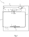
- Fig.1 shows a sectional side view of a sketch of a household microwave appliance 1 with a treatment chamber in the form of a cooking chamber 2.
- the household microwave appliance 1 can be, for example, an oven with microwave functionality.
- the cooking chamber 2 is surrounded by a cooking chamber wall or muffle 3, which has a front loading opening that can be closed with a door 4.
- the household microwave appliance 1 has at least one microwave generator 5 for treating goods located in the cooking chamber 2 (not shown), and possibly also further heating elements such as one or more resistance heating elements (not shown).
- the microwaves generated by the microwave generator 5 are fed into the cooking chamber 2 via a microwave guide 5a by means of a rotating antenna 5b that can be rotated about its longitudinal axis by a stepper motor (not shown).
- an operating device 6 which can have one or more operating elements and/or display devices, e.g. in the form of a touch-sensitive screen.
- the household microwave appliance 1 comprises a rotating plate 7 in the cooking chamber 2, which can be rotated by means of a motor 8 arranged outside the cooking chamber 2.
- the household microwave appliance 1 or its controllable components 5, 6, 8 can be controlled or actuated by means of a central control device 9 (also referred to as "appliance control").
- An evaluation circuit 10 is integrated into the control device 9 and is connected to a combination sniffer line 11.
- the combination sniffer line 11 is the electrical line that leads from the control device 9 to the motor 8 in order to supply the motor 8 with power and/or to transmit data to the motor 8 in order to control it.
- the combination sniffer line 11 is also suitable for alternating currents to be induced in it by microwaves.
- the evaluation circuit 10 is designed to determine alternating currents induced in the antenna line 11.
- the evaluation circuit 10 and the antenna line 11 form a detection device 10, 11 for detecting microwave leakage radiation outside the cooking chamber 2, in particular in a space between the muffle 3 and an outer housing 12 of the household microwave device 1.
- the combination sniffer line 11 therefore has a dual function, namely firstly for power and/or data transmission between the control device 9 and the motor 8 and secondly as a "sensor line" for detecting microwave leakage radiation.
- the combination sniffer line 11 can, for example, be routed around an opening in the muffle 3 through which a drive shaft of the motor 8 leads to the turntable 7.
- the combination sniffer line 11 can, for example, have at least one corrugated or meandering section which, for example, runs over assembly joints, further openings or the like in the muffle 3.
- the household microwave appliance 1 can have at least one pure sniffer line 13 connected to the evaluation circuit 10, e.g. a simple wire or a simple cable, which is only intended to serve as a sensor line.
- the evaluation circuit 10 e.g. a simple wire or a simple cable, which is only intended to serve as a sensor line.
- the combination sniffer line 11 and/or the pure sniffer line 13 can have a length of at least 800 mm, in particular of at least 1000 mm, in particular of at least 1500 mm, in particular of at least 2000 mm.
- Fig.2 shows a plan view of the evaluation circuit 10 integrated in the control device 9 with some other components present on the control device 9.
- Several electrical lines 15 are led to a circuit board 14 of the control device 9.
- the lines 15 can be combination sniffer lines 11, which are connected to their other ends are connected to functional units of the household microwave appliance 1 such as electrical consumers and/or sensors, and/or be pure sniffer lines 13.
- connection points 16 such as terminals or similar, where they merge into corresponding conductor tracks 17 of the circuit board 14.
- connection points 16 such as terminals or similar, where they merge into corresponding conductor tracks 17 of the circuit board 14.
- a processor 18 e.g. a microcontroller, ASIC or FPGA, of the control device 9.
- the evaluation circuit 10 is connected here from the conductor track 17 connected to the combination sniffer line 11 via a coupling capacitor 19, which causes a DC voltage separation between the evaluation circuit 10 and the combination sniffer line 11.
- the evaluation circuit 10 has, as shown in the enlarged section A, at least one ohmic resistor 20, which is connected on the one hand to the connection connected to the processor 18 and on the other hand to a predetermined reference potential or ground.
- the coupling capacitor 19 and the resistor 20 form a high-pass filter 19, 20 for the signal arriving from the combination sniffer line 11.
- the lower cut-off frequency f u is chosen so that practically only the microwave-induced voltage components are allowed to pass.
- the - eg analog - output signal of the evaluation circuit 10 is passed to the processor 18 for evaluation (eg to an analog input of a microcontroller).
- the evaluation circuit 10 can also have other components or parts (not shown), for example an A/D converter, operational amplifier, etc.
- the control device 9 can be set up to detect spark formation in the cooking chamber 2 during microwave operation based on a strength of the microwave-induced alternating current in the combination sniffer line 11, represented by the measurement/output signal or the measured values of the evaluation circuit 10, and to trigger at least one corresponding action if necessary, e.g. to reduce the power of the microwave generator 5, to issue a notice to a user, etc.
- Fig.3 shows a plot of a leakage radiation measurement value LM in mV, representing the strength of the leakage radiation, measured by the evaluation circuit 10, as output by the evaluation circuit 10, for example, against a rotation angle ⁇ of the rotating antenna 5b in degrees during microwave treatment with a power of 600 W of a water load introduced into the cooking chamber 2 without sparking.
- the at least one relevant variable microwave operating parameter here therefore only includes the angle of rotation ⁇ of the rotating antenna 5b, which can assume setting values in a range [0°; 360°], e.g. in steps of 1°, 5° or 10°.
- the rotating antenna 5b serves the purpose of equalizing the microwave power introduced into the food being cooked (not shown). During rotation of the rotating antenna 5b, the microwave field in the cooking chamber 2 is changed cyclically and can cause arcing under unfavorable but unforeseeable conditions and at certain angles of rotation.
- Fig.4 shows a plot of a leakage radiation measurement value LM in mV representing the strength of the leakage radiation against a rotation angle ⁇ of the rotating antenna 5b in degrees during microwave treatment with a power of 600 W, a water load introduced into the cooking chamber 2 and an additional metal baking tray inserted (not shown). Due to the inserted baking tray, microwave-based sparking now occurs.
- Fig.5 shows a plot of a fluctuation range LMS of the leakage radiation measured value LM in mV against a rotation angle ⁇ of the rotating antenna 5b in degrees for the leakage radiation measured values LM from Fig.3 and Fig.4 , each calculated from the standard deviation of the leakage radiation measurements LM for the individual rotation angles ⁇ .
- the number of antenna revolutions used for the evaluation is at least two, but can advantageously be more than two.
- the limit value LMS_thr can be calculated based on the average value of all fluctuation ranges LMS.
- the leakage radiation measured values LM or their curves are subjected to data processing.
- the leakage radiation measurements LM from the first (eg five to ten) seconds of microwave operation cannot be used, since the magnetron 5 is The heating phase has not yet reached a stable vibration state and would therefore possibly cause a spread of the leakage radiation measured values LM even without sparking.
- the leakage radiation measurements LM can also be subjected to curve fitting (e.g. by interpolation) and/or smoothing.
- one countermeasure can be to gradually reduce the microwave power radiated into the cooking chamber 2. As soon as the microwave power has been reduced to such an extent that the breakdown field strength is no longer reached, the spark generation stops immediately, which can be seen in a greatly reduced fluctuation range LMS.
- the household microwave appliance can also initiate an interaction with the user, instructing the user to remove the accessories, reposition them or reduce the set microwave power.
- a numerical value can also include exactly the number stated as well as a usual tolerance range, as long as this is not explicitly excluded.
Landscapes
- Physics & Mathematics (AREA)
- Electromagnetism (AREA)
- Electric Ovens (AREA)
- Control Of High-Frequency Heating Circuits (AREA)
Claims (15)
- Procédé de détermination d'éclatement d'étincelles dans un espace de traitement (2) d'un appareil ménager à micro-ondes (1) pendant le déroulement d'un traitement par micro-ondes au cours duquel une valeur de consigne d'au moins un paramètre d'exploitation à micro-ondes (ϕ) est modifiée, dans lequel dans le procédé- pendant le déroulement d'un traitement par micro-ondes, des valeurs de mesure (LM) d'un rayonnement de fuite sont mesurées plusieurs fois de suite en présence de valeurs de consigne identiques de l'au moins un paramètre d'exploitation à micro-ondes (ϕ) et- un éclatement d'étincelles est détecté lorsqu'une marge de fluctuation (LMS) des valeurs de mesure (LM) mesurées en présence de valeurs de consigne identiques, atteint ou excède une marge de fluctuation prédéfinie (LMS_thr).
- Procédé selon la revendication 1, dans lequel les valeurs de mesure (LM) du rayonnement de fuite sont mesurées au moyen d'une ligne de reniflement (11, 13) disposée en dehors d'un espace de traitement (2).
- Procédé selon l'une des revendications précédentes, dans lequel la marge de fluctuation (LMS) est une différence entre une valeur minimale et une valeur maximale de valeurs de mesure (LM) mesurées en présence de valeurs de consigne identiques de l'au moins un paramètre d'exploitation à micro-ondes.
- Procédé selon l'une des revendications 1 à 2, dans lequel la marge de fluctuation (LMS) est une variation standard de valeurs de mesure (LM) mesurées en présence de valeurs de consigne identiques de l'au moins un paramètre d'exploitation à micro-ondes.
- Procédé selon l'une des revendications précédentes, dans lequel un éclatement d'étincelles est détecté lorsque la marge de fluctuation (LMS) est atteinte ou excédée pour une combinaison de valeurs de consigne de l'au moins un paramètre d'exploitation à micro-ondes (ϕ).
- Procédé selon l'une des revendications 1 à 4, dans lequel un éclatement d'étincelles est détecté lorsque la marge de fluctuation (LMS) est respectivement atteinte ou excédée pour plusieurs combinaisons de valeurs de consigne de l'au moins un paramètre d'exploitation à micro-ondes (ϕ).
- Procédé selon l'une des revendications précédentes, dans lequel la marge de fluctuation prédéfinie (LMS_thr) est prédéfinie de manière fixe pour le déroulement d'un traitement par micro-ondes.
- Procédé selon l'une des revendications précédentes, dans lequel la marge de fluctuation prédéfinie (LMS_thr) est adaptée de façon dynamique à l'aide des valeurs de mesure mesurées (LM).
- Procédé selon la revendication 8, dans lequel la marge de fluctuation prédéfinie (LMS_thr) pour une combinaison déterminée de valeurs de consigne des paramètres d'exploitation à micro-ondes (ϕ) correspond à un produit d'une marge de fluctuation moyenne déterminée pour plusieurs combinaisons de valeurs de consigne et d'un facteur A, où A > 1.
- Procédé selon l'une des revendications précédentes, dans lequel l'au moins un paramètre d'exploitation à micro-ondes (ϕ) comprend au moins un paramètre d'exploitation à micro-ondes issu du groupe- angle de rotation (ϕ) d'au moins une antenne rotative (5b),- angle de rotation d'au moins un répartiteur d'ondes,- angle de rotation d'un plateau tournant (7),- puissance des micro-ondes émises,- fréquence des micro-ondes émises,- phase entre les micro-ondes émises par différents points d'alimentation.
- Procédé selon l'une des revendications précédentes, dans lequel le procédé est seulement effectué à partir d'une durée prédéfinie après le début du déroulement d'un traitement par micro-ondes.
- Procédé d'exploitation d'un appareil ménager à micro-ondes (1), dans lequel au moins une action est déclenchée lorsqu'un éclatement d'étincelles est détecté au moyen du procédé selon l'une des revendications précédentes.
- Procédé selon la revendication 12, dans lequel l'au moins une action comprend une réduction d'une puissance des micro-ondes émises pour l'ensemble des valeurs de consigne de l'au moins un paramètre d'exploitation à micro-ondes (ϕ).
- Procédé selon la revendication 12, dans lequel l'au moins une action comprend une réduction d'une puissance des micro-ondes émises uniquement pour les valeurs de consigne de l'au moins un paramètre d'exploitation à micro-ondes (ϕ) pour lesquelles la marge de fluctuation prédéfinie (LMS_thr) est excédée.
- Appareil ménager à micro-ondes (1), présentant un générateur de micro-ondes (5) pour la production de micro-ondes, un espace de traitement (2) pouvant être alimenté au moyen des micro-ondes produites, un dispositif de détection de micro-ondes (10, 11) pour mesurer le rayonnement de fuite de micro-ondes s'écoulant de l'espace de traitement (2) et un dispositif de traitement des données (10) pour la détection d'un éclatement d'étincelles par évaluation du rayonnement de fuite de micro-ondes (LM) mesuré par le dispositif de détection de micro-ondes (10, 11), dans lequel l'appareil ménager à micro-ondes (1) est aménagé afin d'effectuer le procéder selon l'une des revendications précédentes.
Applications Claiming Priority (2)
| Application Number | Priority Date | Filing Date | Title |
|---|---|---|---|
| DE102020208535.8A DE102020208535A1 (de) | 2020-07-08 | 2020-07-08 | Feststellen von Funkenüberschlägen während eines Mikrowellen-Behandlungsablaufs eines Haushalts-Mikrowellengeräts |
| PCT/EP2021/067287 WO2022008257A1 (fr) | 2020-07-08 | 2021-06-24 | Détermination d'éclatements d'étincelles pendant le déroulement d'un traitement par micro-ondes d'un appareil ménager à micro-ondes |
Publications (2)
| Publication Number | Publication Date |
|---|---|
| EP4179846A1 EP4179846A1 (fr) | 2023-05-17 |
| EP4179846B1 true EP4179846B1 (fr) | 2024-08-14 |
Family
ID=76765113
Family Applications (1)
| Application Number | Title | Priority Date | Filing Date |
|---|---|---|---|
| EP21737363.8A Active EP4179846B1 (fr) | 2020-07-08 | 2021-06-24 | Détermination d'éclatements d'étincelles pendant le déroulement d'un traitement par micro-ondes d'un appareil ménager à micro-ondes |
Country Status (5)
| Country | Link |
|---|---|
| US (1) | US12507326B2 (fr) |
| EP (1) | EP4179846B1 (fr) |
| CN (1) | CN115777235A (fr) |
| DE (1) | DE102020208535A1 (fr) |
| WO (1) | WO2022008257A1 (fr) |
Families Citing this family (3)
| Publication number | Priority date | Publication date | Assignee | Title |
|---|---|---|---|---|
| KR102955361B1 (ko) * | 2021-08-27 | 2026-04-20 | 삼성전자주식회사 | 플라즈마의 파라미터를 계측하는 방법, 플라즈마 파라미터를 계측하는 장치, 플라즈마 처리 시스템 및 웨이퍼 처리 방법 |
| DE102022202795A1 (de) * | 2022-03-22 | 2023-09-28 | Robert Bosch Gesellschaft mit beschränkter Haftung | Verfahren zur Ermittlung einer Wiederholstreuung |
| CN116908636B (zh) * | 2023-07-17 | 2024-06-25 | 北京中陆汇能科技有限公司 | 一种基于自调节比较点的火花闪络判断方法和电路 |
Family Cites Families (17)
| Publication number | Priority date | Publication date | Assignee | Title |
|---|---|---|---|---|
| DE2029559C3 (de) | 1970-01-17 | 1974-08-08 | Industrie A. Zanussi S.P.A., Pordenone (Italien) | Sicherheitsvorrichtung gegen den Austritt von Strahlungen aus Mikrowellengeräten |
| US3746824A (en) | 1972-08-07 | 1973-07-17 | Gen Electric | Microwave oven leakage radiation detecting device |
| US3748424A (en) | 1972-08-07 | 1973-07-24 | Gen Electric | Built-in leakage radiation detecting device for a microwave oven |
| US4354153A (en) * | 1979-11-19 | 1982-10-12 | Litton Systems, Inc. | Microwave oven leakage detector and method of using same to test door seal leakage |
| DE19537755A1 (de) | 1995-10-10 | 1997-04-30 | Mikrowellen Systeme Mws Gmbh | Mikrowellenofen, insbesondere für ein Labor |
| US7525074B2 (en) | 2006-05-31 | 2009-04-28 | International Business Machines Corporation | Method and apparatus for detecting metal placed within a microwave oven |
| JP2009019796A (ja) | 2007-07-11 | 2009-01-29 | Panasonic Corp | 電子レンジ |
| DE102007051638B8 (de) * | 2007-10-26 | 2010-06-10 | Rational Ag | Verfahren zur Erkennung des Beladungszustandes eines Gargerätes mit Mikrowellengaren und Gargerät zur Durchführung solch eines Verfahrens |
| JP2009127923A (ja) * | 2007-11-22 | 2009-06-11 | Panasonic Corp | 電子レンジ |
| JP2009127922A (ja) * | 2007-11-22 | 2009-06-11 | Panasonic Corp | 電子レンジ |
| JP2009250444A (ja) | 2008-04-01 | 2009-10-29 | Panasonic Corp | 電子レンジ |
| DE502008002740D1 (de) | 2008-07-21 | 2011-04-14 | Topinox Sarl | Verfahren und Vorrichtung zur Mikrowellen-Leckageüberwachung bei einem Gargerät |
| EP2152047A1 (fr) | 2008-08-04 | 2010-02-10 | Topinox Sarl | Dispositif de sécurité destiné à la détection de rayonnement de fuite |
| DE102010036913A1 (de) | 2010-08-09 | 2012-02-09 | Miele & Cie. Kg | Gargerät |
| EP2880963A4 (fr) | 2012-08-06 | 2015-08-12 | Goji Ltd | Procédé permettant de détecter une décharge obscure et dispositif utilisant le procédé |
| US11032878B2 (en) | 2016-09-26 | 2021-06-08 | Illinois Tool Works Inc. | Method for managing a microwave heating device and microwave heating device |
| JP6361049B2 (ja) * | 2017-08-07 | 2018-07-25 | 光洋サーモシステム株式会社 | マイクロ波監視装置、マイクロ波加熱装置、および、マイクロ波監視方法 |
-
2020
- 2020-07-08 DE DE102020208535.8A patent/DE102020208535A1/de not_active Withdrawn
-
2021
- 2021-06-24 EP EP21737363.8A patent/EP4179846B1/fr active Active
- 2021-06-24 CN CN202180048394.6A patent/CN115777235A/zh active Pending
- 2021-06-24 WO PCT/EP2021/067287 patent/WO2022008257A1/fr not_active Ceased
- 2021-06-24 US US18/010,476 patent/US12507326B2/en active Active
Also Published As
| Publication number | Publication date |
|---|---|
| WO2022008257A1 (fr) | 2022-01-13 |
| DE102020208535A1 (de) | 2022-01-13 |
| CN115777235A (zh) | 2023-03-10 |
| US12507326B2 (en) | 2025-12-23 |
| US20230135333A1 (en) | 2023-05-04 |
| EP4179846A1 (fr) | 2023-05-17 |
Similar Documents
| Publication | Publication Date | Title |
|---|---|---|
| EP2236004B1 (fr) | Plaque de cuisson à induction munie d'une pluralité d'éléments chauffants à induction | |
| DE60028485T2 (de) | Objekterfassungssystem, welches zum Beispiel die Anwesenheit eines metallischen Kochgerätes auf einer nichtmetallischen Kochoberfläche erfasst | |
| DE102007051638B3 (de) | Verfahren zur Erkennung des Beladungszustandes eines Gargerätes mit Mikrowellengaren und Gargerät zur Durchführung solch eines Verfahrens | |
| EP4179846A1 (fr) | Détermination d'éclatements d'étincelles pendant le déroulement d'un traitement par micro-ondes d'un appareil ménager à micro-ondes | |
| DE102011052847A1 (de) | Verfahren und Vorrichtung zur Entstörung von Feuchtesensor-Signalen | |
| EP3861359B1 (fr) | Procédé pour déterminer un court-circuit à l'apparition d'un arc électrique sur un conducteur électrique | |
| EP1087640A2 (fr) | Dispositif de reconnaissance de présence et/ou de taille d'un pot | |
| DE10150545C1 (de) | Mikrowellenofen mit Magnetfeld-Erfassungsvorrichtung | |
| EP3105000B1 (fr) | Machine de découpe par plasma avec système de protection ainsi que procédé d'exploitation de la machine de découpe par plasma | |
| EP3637948B1 (fr) | Dispositif de chauffage et procédé d'enregistrement de température sur un dispositif de chauffage | |
| EP1705687B1 (fr) | Procédé de détection d'arc | |
| DE2507175A1 (de) | Temperaturueberwachungsvorrichtung fuer mikrowellenherde | |
| EP3977817B1 (fr) | Appareil ménager à micro-ondes à équipement de détection pour la détection de rayonnement de fuite de micro-ondes | |
| EP3997961B1 (fr) | Four à micro-ondes domestique avec dispositif de variation de mode | |
| EP2418916B1 (fr) | Appareil de cuisson | |
| DE69809536T2 (de) | Magnetronsteuersschaltung bei einem Mikrowellenofen | |
| DE202004020402U1 (de) | Vorrichtung zur Erkennung von Störlichtbögen | |
| EP3368829B1 (fr) | Dispositif de chauffage d'appareil ménager | |
| DE19754351C1 (de) | Verfahren und Vorrichtung zur Messung der Temperatur einer Wicklung | |
| DE102018105901A1 (de) | Gargerät, umfassend einen Garraum und ein Magnetron zur Erzeugung von elektromagnetischer Energie, und Verfahren zum Betrieb eines derartigen Gargeräts | |
| EP1768461A1 (fr) | Méthode pour générer, traiter et évaluer un signal en correlation avec la température, et dispositif correspondant | |
| EP3443267A1 (fr) | Appareil de cuisson présentant une antenne plane et procédé pour faire fonctionner l'appareil de cuisson | |
| EP4042836B1 (fr) | Détection d'un arrêt d'un dispositif rotatif de distribution de micro-ondes | |
| EP4539602B1 (fr) | Capteur de température à coeur et appareil de cuisson combiné avec capteur de température à coeur | |
| EP3496509A1 (fr) | Dispositif formant appareil de cuisson |
Legal Events
| Date | Code | Title | Description |
|---|---|---|---|
| STAA | Information on the status of an ep patent application or granted ep patent |
Free format text: STATUS: UNKNOWN |
|
| STAA | Information on the status of an ep patent application or granted ep patent |
Free format text: STATUS: THE INTERNATIONAL PUBLICATION HAS BEEN MADE |
|
| PUAI | Public reference made under article 153(3) epc to a published international application that has entered the european phase |
Free format text: ORIGINAL CODE: 0009012 |
|
| STAA | Information on the status of an ep patent application or granted ep patent |
Free format text: STATUS: REQUEST FOR EXAMINATION WAS MADE |
|
| 17P | Request for examination filed |
Effective date: 20230208 |
|
| AK | Designated contracting states |
Kind code of ref document: A1 Designated state(s): AL AT BE BG CH CY CZ DE DK EE ES FI FR GB GR HR HU IE IS IT LI LT LU LV MC MK MT NL NO PL PT RO RS SE SI SK SM TR |
|
| DAV | Request for validation of the european patent (deleted) | ||
| DAX | Request for extension of the european patent (deleted) | ||
| GRAP | Despatch of communication of intention to grant a patent |
Free format text: ORIGINAL CODE: EPIDOSNIGR1 |
|
| STAA | Information on the status of an ep patent application or granted ep patent |
Free format text: STATUS: GRANT OF PATENT IS INTENDED |
|
| INTG | Intention to grant announced |
Effective date: 20240402 |
|
| GRAS | Grant fee paid |
Free format text: ORIGINAL CODE: EPIDOSNIGR3 |
|
| GRAA | (expected) grant |
Free format text: ORIGINAL CODE: 0009210 |
|
| STAA | Information on the status of an ep patent application or granted ep patent |
Free format text: STATUS: THE PATENT HAS BEEN GRANTED |
|
| AK | Designated contracting states |
Kind code of ref document: B1 Designated state(s): AL AT BE BG CH CY CZ DE DK EE ES FI FR GB GR HR HU IE IS IT LI LT LU LV MC MK MT NL NO PL PT RO RS SE SI SK SM TR |
|
| REG | Reference to a national code |
Ref country code: GB Ref legal event code: FG4D Free format text: NOT ENGLISH |
|
| REG | Reference to a national code |
Ref country code: CH Ref legal event code: EP |
|
| REG | Reference to a national code |
Ref country code: DE Ref legal event code: R096 Ref document number: 502021004794 Country of ref document: DE |
|
| REG | Reference to a national code |
Ref country code: NL Ref legal event code: FP |
|
| REG | Reference to a national code |
Ref country code: IE Ref legal event code: FG4D Free format text: LANGUAGE OF EP DOCUMENT: GERMAN |
|
| REG | Reference to a national code |
Ref country code: LT Ref legal event code: MG9D |
|
| PG25 | Lapsed in a contracting state [announced via postgrant information from national office to epo] |
Ref country code: NO Free format text: LAPSE BECAUSE OF FAILURE TO SUBMIT A TRANSLATION OF THE DESCRIPTION OR TO PAY THE FEE WITHIN THE PRESCRIBED TIME-LIMIT Effective date: 20241114 |
|
| PG25 | Lapsed in a contracting state [announced via postgrant information from national office to epo] |
Ref country code: FI Free format text: LAPSE BECAUSE OF FAILURE TO SUBMIT A TRANSLATION OF THE DESCRIPTION OR TO PAY THE FEE WITHIN THE PRESCRIBED TIME-LIMIT Effective date: 20240814 Ref country code: GR Free format text: LAPSE BECAUSE OF FAILURE TO SUBMIT A TRANSLATION OF THE DESCRIPTION OR TO PAY THE FEE WITHIN THE PRESCRIBED TIME-LIMIT Effective date: 20241115 Ref country code: PL Free format text: LAPSE BECAUSE OF FAILURE TO SUBMIT A TRANSLATION OF THE DESCRIPTION OR TO PAY THE FEE WITHIN THE PRESCRIBED TIME-LIMIT Effective date: 20240814 Ref country code: PT Free format text: LAPSE BECAUSE OF FAILURE TO SUBMIT A TRANSLATION OF THE DESCRIPTION OR TO PAY THE FEE WITHIN THE PRESCRIBED TIME-LIMIT Effective date: 20241216 |
|
| PG25 | Lapsed in a contracting state [announced via postgrant information from national office to epo] |
Ref country code: BG Free format text: LAPSE BECAUSE OF FAILURE TO SUBMIT A TRANSLATION OF THE DESCRIPTION OR TO PAY THE FEE WITHIN THE PRESCRIBED TIME-LIMIT Effective date: 20240814 |
|
| PG25 | Lapsed in a contracting state [announced via postgrant information from national office to epo] |
Ref country code: LV Free format text: LAPSE BECAUSE OF FAILURE TO SUBMIT A TRANSLATION OF THE DESCRIPTION OR TO PAY THE FEE WITHIN THE PRESCRIBED TIME-LIMIT Effective date: 20240814 |
|
| PG25 | Lapsed in a contracting state [announced via postgrant information from national office to epo] |
Ref country code: IS Free format text: LAPSE BECAUSE OF FAILURE TO SUBMIT A TRANSLATION OF THE DESCRIPTION OR TO PAY THE FEE WITHIN THE PRESCRIBED TIME-LIMIT Effective date: 20241214 |
|
| PG25 | Lapsed in a contracting state [announced via postgrant information from national office to epo] |
Ref country code: HR Free format text: LAPSE BECAUSE OF FAILURE TO SUBMIT A TRANSLATION OF THE DESCRIPTION OR TO PAY THE FEE WITHIN THE PRESCRIBED TIME-LIMIT Effective date: 20240814 |
|
| PG25 | Lapsed in a contracting state [announced via postgrant information from national office to epo] |
Ref country code: RS Free format text: LAPSE BECAUSE OF FAILURE TO SUBMIT A TRANSLATION OF THE DESCRIPTION OR TO PAY THE FEE WITHIN THE PRESCRIBED TIME-LIMIT Effective date: 20241114 Ref country code: ES Free format text: LAPSE BECAUSE OF FAILURE TO SUBMIT A TRANSLATION OF THE DESCRIPTION OR TO PAY THE FEE WITHIN THE PRESCRIBED TIME-LIMIT Effective date: 20240814 |
|
| PG25 | Lapsed in a contracting state [announced via postgrant information from national office to epo] |
Ref country code: RS Free format text: LAPSE BECAUSE OF FAILURE TO SUBMIT A TRANSLATION OF THE DESCRIPTION OR TO PAY THE FEE WITHIN THE PRESCRIBED TIME-LIMIT Effective date: 20241114 Ref country code: PT Free format text: LAPSE BECAUSE OF FAILURE TO SUBMIT A TRANSLATION OF THE DESCRIPTION OR TO PAY THE FEE WITHIN THE PRESCRIBED TIME-LIMIT Effective date: 20241216 Ref country code: PL Free format text: LAPSE BECAUSE OF FAILURE TO SUBMIT A TRANSLATION OF THE DESCRIPTION OR TO PAY THE FEE WITHIN THE PRESCRIBED TIME-LIMIT Effective date: 20240814 Ref country code: NO Free format text: LAPSE BECAUSE OF FAILURE TO SUBMIT A TRANSLATION OF THE DESCRIPTION OR TO PAY THE FEE WITHIN THE PRESCRIBED TIME-LIMIT Effective date: 20241114 Ref country code: LV Free format text: LAPSE BECAUSE OF FAILURE TO SUBMIT A TRANSLATION OF THE DESCRIPTION OR TO PAY THE FEE WITHIN THE PRESCRIBED TIME-LIMIT Effective date: 20240814 Ref country code: IS Free format text: LAPSE BECAUSE OF FAILURE TO SUBMIT A TRANSLATION OF THE DESCRIPTION OR TO PAY THE FEE WITHIN THE PRESCRIBED TIME-LIMIT Effective date: 20241214 Ref country code: HR Free format text: LAPSE BECAUSE OF FAILURE TO SUBMIT A TRANSLATION OF THE DESCRIPTION OR TO PAY THE FEE WITHIN THE PRESCRIBED TIME-LIMIT Effective date: 20240814 Ref country code: GR Free format text: LAPSE BECAUSE OF FAILURE TO SUBMIT A TRANSLATION OF THE DESCRIPTION OR TO PAY THE FEE WITHIN THE PRESCRIBED TIME-LIMIT Effective date: 20241115 Ref country code: FI Free format text: LAPSE BECAUSE OF FAILURE TO SUBMIT A TRANSLATION OF THE DESCRIPTION OR TO PAY THE FEE WITHIN THE PRESCRIBED TIME-LIMIT Effective date: 20240814 Ref country code: ES Free format text: LAPSE BECAUSE OF FAILURE TO SUBMIT A TRANSLATION OF THE DESCRIPTION OR TO PAY THE FEE WITHIN THE PRESCRIBED TIME-LIMIT Effective date: 20240814 Ref country code: BG Free format text: LAPSE BECAUSE OF FAILURE TO SUBMIT A TRANSLATION OF THE DESCRIPTION OR TO PAY THE FEE WITHIN THE PRESCRIBED TIME-LIMIT Effective date: 20240814 |
|
| PG25 | Lapsed in a contracting state [announced via postgrant information from national office to epo] |
Ref country code: SM Free format text: LAPSE BECAUSE OF FAILURE TO SUBMIT A TRANSLATION OF THE DESCRIPTION OR TO PAY THE FEE WITHIN THE PRESCRIBED TIME-LIMIT Effective date: 20240814 Ref country code: RO Free format text: LAPSE BECAUSE OF FAILURE TO SUBMIT A TRANSLATION OF THE DESCRIPTION OR TO PAY THE FEE WITHIN THE PRESCRIBED TIME-LIMIT Effective date: 20240814 Ref country code: DK Free format text: LAPSE BECAUSE OF FAILURE TO SUBMIT A TRANSLATION OF THE DESCRIPTION OR TO PAY THE FEE WITHIN THE PRESCRIBED TIME-LIMIT Effective date: 20240814 |
|
| PG25 | Lapsed in a contracting state [announced via postgrant information from national office to epo] |
Ref country code: EE Free format text: LAPSE BECAUSE OF FAILURE TO SUBMIT A TRANSLATION OF THE DESCRIPTION OR TO PAY THE FEE WITHIN THE PRESCRIBED TIME-LIMIT Effective date: 20240814 |
|
| PG25 | Lapsed in a contracting state [announced via postgrant information from national office to epo] |
Ref country code: CZ Free format text: LAPSE BECAUSE OF FAILURE TO SUBMIT A TRANSLATION OF THE DESCRIPTION OR TO PAY THE FEE WITHIN THE PRESCRIBED TIME-LIMIT Effective date: 20240814 |
|
| PG25 | Lapsed in a contracting state [announced via postgrant information from national office to epo] |
Ref country code: SK Free format text: LAPSE BECAUSE OF FAILURE TO SUBMIT A TRANSLATION OF THE DESCRIPTION OR TO PAY THE FEE WITHIN THE PRESCRIBED TIME-LIMIT Effective date: 20240814 Ref country code: IT Free format text: LAPSE BECAUSE OF FAILURE TO SUBMIT A TRANSLATION OF THE DESCRIPTION OR TO PAY THE FEE WITHIN THE PRESCRIBED TIME-LIMIT Effective date: 20240814 |
|
| REG | Reference to a national code |
Ref country code: DE Ref legal event code: R097 Ref document number: 502021004794 Country of ref document: DE |
|
| PLBE | No opposition filed within time limit |
Free format text: ORIGINAL CODE: 0009261 |
|
| STAA | Information on the status of an ep patent application or granted ep patent |
Free format text: STATUS: NO OPPOSITION FILED WITHIN TIME LIMIT |
|
| PGFP | Annual fee paid to national office [announced via postgrant information from national office to epo] |
Ref country code: DE Payment date: 20250630 Year of fee payment: 5 |
|
| PGFP | Annual fee paid to national office [announced via postgrant information from national office to epo] |
Ref country code: GB Payment date: 20250620 Year of fee payment: 5 |
|
| PGFP | Annual fee paid to national office [announced via postgrant information from national office to epo] |
Ref country code: NL Payment date: 20250618 Year of fee payment: 5 |
|
| PGFP | Annual fee paid to national office [announced via postgrant information from national office to epo] |
Ref country code: FR Payment date: 20250624 Year of fee payment: 5 |
|
| 26N | No opposition filed |
Effective date: 20250515 |
|
| PGFP | Annual fee paid to national office [announced via postgrant information from national office to epo] |
Ref country code: AT Payment date: 20250721 Year of fee payment: 5 |
|
| PG25 | Lapsed in a contracting state [announced via postgrant information from national office to epo] |
Ref country code: SE Free format text: LAPSE BECAUSE OF FAILURE TO SUBMIT A TRANSLATION OF THE DESCRIPTION OR TO PAY THE FEE WITHIN THE PRESCRIBED TIME-LIMIT Effective date: 20240814 |
|
| REG | Reference to a national code |
Ref country code: CH Ref legal event code: H13 Free format text: ST27 STATUS EVENT CODE: U-0-0-H10-H13 (AS PROVIDED BY THE NATIONAL OFFICE) Effective date: 20260127 |
|
| PG25 | Lapsed in a contracting state [announced via postgrant information from national office to epo] |
Ref country code: MC Free format text: LAPSE BECAUSE OF FAILURE TO SUBMIT A TRANSLATION OF THE DESCRIPTION OR TO PAY THE FEE WITHIN THE PRESCRIBED TIME-LIMIT Effective date: 20240814 |
|
| PG25 | Lapsed in a contracting state [announced via postgrant information from national office to epo] |
Ref country code: LU Free format text: LAPSE BECAUSE OF NON-PAYMENT OF DUE FEES Effective date: 20250624 |
|
| REG | Reference to a national code |
Ref country code: BE Ref legal event code: MM Effective date: 20250630 |
|
| PG25 | Lapsed in a contracting state [announced via postgrant information from national office to epo] |
Ref country code: IE Free format text: LAPSE BECAUSE OF NON-PAYMENT OF DUE FEES Effective date: 20250624 |
|
| PG25 | Lapsed in a contracting state [announced via postgrant information from national office to epo] |
Ref country code: BE Free format text: LAPSE BECAUSE OF NON-PAYMENT OF DUE FEES Effective date: 20250630 |
|
| PG25 | Lapsed in a contracting state [announced via postgrant information from national office to epo] |
Ref country code: CH Free format text: LAPSE BECAUSE OF NON-PAYMENT OF DUE FEES Effective date: 20250630 |