EP4179871A1 - Système de remplissage d'eau pour centre de jardin d'intérieur et son procédé de fonctionnement - Google Patents
Système de remplissage d'eau pour centre de jardin d'intérieur et son procédé de fonctionnement Download PDFInfo
- Publication number
- EP4179871A1 EP4179871A1 EP21841305.2A EP21841305A EP4179871A1 EP 4179871 A1 EP4179871 A1 EP 4179871A1 EP 21841305 A EP21841305 A EP 21841305A EP 4179871 A1 EP4179871 A1 EP 4179871A1
- Authority
- EP
- European Patent Office
- Prior art keywords
- air
- flow
- chamber
- stopping
- hydration
- Prior art date
- Legal status (The legal status is an assumption and is not a legal conclusion. Google has not performed a legal analysis and makes no representation as to the accuracy of the status listed.)
- Pending
Links
- XLYOFNOQVPJJNP-UHFFFAOYSA-N water Substances O XLYOFNOQVPJJNP-UHFFFAOYSA-N 0.000 title claims abstract description 50
- 238000011017 operating method Methods 0.000 title abstract 2
- 239000012530 fluid Substances 0.000 claims abstract description 17
- 238000004891 communication Methods 0.000 claims abstract description 15
- 230000003287 optical effect Effects 0.000 claims abstract description 6
- 238000010413 gardening Methods 0.000 claims description 63
- 230000036571 hydration Effects 0.000 claims description 62
- 238000006703 hydration reaction Methods 0.000 claims description 62
- 238000000034 method Methods 0.000 claims description 28
- 230000001105 regulatory effect Effects 0.000 claims description 17
- 239000007788 liquid Substances 0.000 claims description 13
- 238000001514 detection method Methods 0.000 claims description 10
- 230000012010 growth Effects 0.000 abstract description 7
- 239000003595 mist Substances 0.000 abstract description 5
- 241000196324 Embryophyta Species 0.000 description 36
- 239000003507 refrigerant Substances 0.000 description 19
- 230000007613 environmental effect Effects 0.000 description 14
- 238000005192 partition Methods 0.000 description 13
- 238000012545 processing Methods 0.000 description 8
- 235000015097 nutrients Nutrition 0.000 description 7
- 238000012986 modification Methods 0.000 description 5
- 230000004048 modification Effects 0.000 description 5
- 239000000203 mixture Substances 0.000 description 4
- 230000000712 assembly Effects 0.000 description 3
- 238000000429 assembly Methods 0.000 description 3
- 238000001816 cooling Methods 0.000 description 3
- 230000008635 plant growth Effects 0.000 description 3
- 238000012546 transfer Methods 0.000 description 3
- 230000005540 biological transmission Effects 0.000 description 2
- 238000007599 discharging Methods 0.000 description 2
- 238000010438 heat treatment Methods 0.000 description 2
- 230000000887 hydrating effect Effects 0.000 description 2
- 239000000463 material Substances 0.000 description 2
- 230000003134 recirculating effect Effects 0.000 description 2
- 230000004044 response Effects 0.000 description 2
- 239000011555 saturated liquid Substances 0.000 description 2
- 239000007921 spray Substances 0.000 description 2
- 238000011144 upstream manufacturing Methods 0.000 description 2
- 235000001674 Agaricus brunnescens Nutrition 0.000 description 1
- 241000195493 Cryptophyta Species 0.000 description 1
- 241000233866 Fungi Species 0.000 description 1
- 230000009286 beneficial effect Effects 0.000 description 1
- 230000000903 blocking effect Effects 0.000 description 1
- 239000003086 colorant Substances 0.000 description 1
- 238000007906 compression Methods 0.000 description 1
- 238000010276 construction Methods 0.000 description 1
- 230000001276 controlling effect Effects 0.000 description 1
- 239000012153 distilled water Substances 0.000 description 1
- 230000000694 effects Effects 0.000 description 1
- 238000005516 engineering process Methods 0.000 description 1
- 239000000835 fiber Substances 0.000 description 1
- 238000001914 filtration Methods 0.000 description 1
- 239000007789 gas Substances 0.000 description 1
- 239000011521 glass Substances 0.000 description 1
- 229910052736 halogen Inorganic materials 0.000 description 1
- 150000002367 halogens Chemical class 0.000 description 1
- 238000003306 harvesting Methods 0.000 description 1
- 235000008216 herbs Nutrition 0.000 description 1
- 230000006698 induction Effects 0.000 description 1
- 238000005259 measurement Methods 0.000 description 1
- 230000007246 mechanism Effects 0.000 description 1
- 238000012544 monitoring process Methods 0.000 description 1
- 230000037361 pathway Effects 0.000 description 1
- 230000029553 photosynthesis Effects 0.000 description 1
- 238000010672 photosynthesis Methods 0.000 description 1
- 230000010287 polarization Effects 0.000 description 1
- 238000013138 pruning Methods 0.000 description 1
- 239000004065 semiconductor Substances 0.000 description 1
- 238000000638 solvent extraction Methods 0.000 description 1
- 238000005507 spraying Methods 0.000 description 1
- 230000001360 synchronised effect Effects 0.000 description 1
- 238000011282 treatment Methods 0.000 description 1
- 235000013311 vegetables Nutrition 0.000 description 1
Images





Classifications
-
- A—HUMAN NECESSITIES
- A01—AGRICULTURE; FORESTRY; ANIMAL HUSBANDRY; HUNTING; TRAPPING; FISHING
- A01G—HORTICULTURE; CULTIVATION OF VEGETABLES, FLOWERS, RICE, FRUIT, VINES, HOPS OR SEAWEED; FORESTRY; WATERING
- A01G9/00—Cultivation in receptacles, forcing-frames or greenhouses; Edging for beds, lawn or the like
- A01G9/24—Devices or systems for heating, ventilating, regulating temperature, illuminating, or watering, in greenhouses, forcing-frames, or the like
- A01G9/246—Air-conditioning systems
-
- A—HUMAN NECESSITIES
- A01—AGRICULTURE; FORESTRY; ANIMAL HUSBANDRY; HUNTING; TRAPPING; FISHING
- A01G—HORTICULTURE; CULTIVATION OF VEGETABLES, FLOWERS, RICE, FRUIT, VINES, HOPS OR SEAWEED; FORESTRY; WATERING
- A01G27/00—Self-acting watering devices, e.g. for flower-pots
- A01G27/001—Self-acting watering devices, e.g. for flower-pots with intermittent watering means
-
- A—HUMAN NECESSITIES
- A01—AGRICULTURE; FORESTRY; ANIMAL HUSBANDRY; HUNTING; TRAPPING; FISHING
- A01G—HORTICULTURE; CULTIVATION OF VEGETABLES, FLOWERS, RICE, FRUIT, VINES, HOPS OR SEAWEED; FORESTRY; WATERING
- A01G27/00—Self-acting watering devices, e.g. for flower-pots
- A01G27/003—Control of self-acting watering devices
-
- A—HUMAN NECESSITIES
- A01—AGRICULTURE; FORESTRY; ANIMAL HUSBANDRY; HUNTING; TRAPPING; FISHING
- A01G—HORTICULTURE; CULTIVATION OF VEGETABLES, FLOWERS, RICE, FRUIT, VINES, HOPS OR SEAWEED; FORESTRY; WATERING
- A01G27/00—Self-acting watering devices, e.g. for flower-pots
- A01G27/006—Reservoirs, separate from plant-pots, dispensing directly into rooting medium
-
- A—HUMAN NECESSITIES
- A01—AGRICULTURE; FORESTRY; ANIMAL HUSBANDRY; HUNTING; TRAPPING; FISHING
- A01G—HORTICULTURE; CULTIVATION OF VEGETABLES, FLOWERS, RICE, FRUIT, VINES, HOPS OR SEAWEED; FORESTRY; WATERING
- A01G9/00—Cultivation in receptacles, forcing-frames or greenhouses; Edging for beds, lawn or the like
-
- A—HUMAN NECESSITIES
- A01—AGRICULTURE; FORESTRY; ANIMAL HUSBANDRY; HUNTING; TRAPPING; FISHING
- A01G—HORTICULTURE; CULTIVATION OF VEGETABLES, FLOWERS, RICE, FRUIT, VINES, HOPS OR SEAWEED; FORESTRY; WATERING
- A01G9/00—Cultivation in receptacles, forcing-frames or greenhouses; Edging for beds, lawn or the like
- A01G9/24—Devices or systems for heating, ventilating, regulating temperature, illuminating, or watering, in greenhouses, forcing-frames, or the like
- A01G9/247—Watering arrangements
-
- A—HUMAN NECESSITIES
- A01—AGRICULTURE; FORESTRY; ANIMAL HUSBANDRY; HUNTING; TRAPPING; FISHING
- A01G—HORTICULTURE; CULTIVATION OF VEGETABLES, FLOWERS, RICE, FRUIT, VINES, HOPS OR SEAWEED; FORESTRY; WATERING
- A01G9/00—Cultivation in receptacles, forcing-frames or greenhouses; Edging for beds, lawn or the like
- A01G9/24—Devices or systems for heating, ventilating, regulating temperature, illuminating, or watering, in greenhouses, forcing-frames, or the like
- A01G9/26—Electric devices
-
- A—HUMAN NECESSITIES
- A01—AGRICULTURE; FORESTRY; ANIMAL HUSBANDRY; HUNTING; TRAPPING; FISHING
- A01G—HORTICULTURE; CULTIVATION OF VEGETABLES, FLOWERS, RICE, FRUIT, VINES, HOPS OR SEAWEED; FORESTRY; WATERING
- A01G9/00—Cultivation in receptacles, forcing-frames or greenhouses; Edging for beds, lawn or the like
- A01G9/02—Receptacles, e.g. flower-pots or boxes; Glasses for cultivating flowers
- A01G9/021—Pots formed in one piece; Materials used therefor
-
- A—HUMAN NECESSITIES
- A01—AGRICULTURE; FORESTRY; ANIMAL HUSBANDRY; HUNTING; TRAPPING; FISHING
- A01G—HORTICULTURE; CULTIVATION OF VEGETABLES, FLOWERS, RICE, FRUIT, VINES, HOPS OR SEAWEED; FORESTRY; WATERING
- A01G9/00—Cultivation in receptacles, forcing-frames or greenhouses; Edging for beds, lawn or the like
- A01G9/02—Receptacles, e.g. flower-pots or boxes; Glasses for cultivating flowers
- A01G9/022—Pots for vertical horticulture
- A01G9/023—Multi-tiered planters
-
- A—HUMAN NECESSITIES
- A01—AGRICULTURE; FORESTRY; ANIMAL HUSBANDRY; HUNTING; TRAPPING; FISHING
- A01G—HORTICULTURE; CULTIVATION OF VEGETABLES, FLOWERS, RICE, FRUIT, VINES, HOPS OR SEAWEED; FORESTRY; WATERING
- A01G9/00—Cultivation in receptacles, forcing-frames or greenhouses; Edging for beds, lawn or the like
- A01G9/02—Receptacles, e.g. flower-pots or boxes; Glasses for cultivating flowers
- A01G9/027—Pots connected in horizontal rows
-
- Y—GENERAL TAGGING OF NEW TECHNOLOGICAL DEVELOPMENTS; GENERAL TAGGING OF CROSS-SECTIONAL TECHNOLOGIES SPANNING OVER SEVERAL SECTIONS OF THE IPC; TECHNICAL SUBJECTS COVERED BY FORMER USPC CROSS-REFERENCE ART COLLECTIONS [XRACs] AND DIGESTS
- Y02—TECHNOLOGIES OR APPLICATIONS FOR MITIGATION OR ADAPTATION AGAINST CLIMATE CHANGE
- Y02A—TECHNOLOGIES FOR ADAPTATION TO CLIMATE CHANGE
- Y02A40/00—Adaptation technologies in agriculture, forestry, livestock or agroalimentary production
- Y02A40/10—Adaptation technologies in agriculture, forestry, livestock or agroalimentary production in agriculture
- Y02A40/25—Greenhouse technology, e.g. cooling systems therefor
-
- Y—GENERAL TAGGING OF NEW TECHNOLOGICAL DEVELOPMENTS; GENERAL TAGGING OF CROSS-SECTIONAL TECHNOLOGIES SPANNING OVER SEVERAL SECTIONS OF THE IPC; TECHNICAL SUBJECTS COVERED BY FORMER USPC CROSS-REFERENCE ART COLLECTIONS [XRACs] AND DIGESTS
- Y02—TECHNOLOGIES OR APPLICATIONS FOR MITIGATION OR ADAPTATION AGAINST CLIMATE CHANGE
- Y02P—CLIMATE CHANGE MITIGATION TECHNOLOGIES IN THE PRODUCTION OR PROCESSING OF GOODS
- Y02P60/00—Technologies relating to agriculture, livestock or agroalimentary industries
- Y02P60/20—Reduction of greenhouse gas [GHG] emissions in agriculture, e.g. CO2
- Y02P60/21—Dinitrogen oxide [N2O], e.g. using aquaponics, hydroponics or efficiency measures
Definitions
- the present subject matter relates generally to systems for gardening plants indoors, and more particularly, to a system and method for hydrating plants within an indoor gardening appliance.
- indoor garden centers include a cabinet defining a grow chamber having a number of trays or racks positioned therein to support seedlings or plant material, e.g., for growing herbs, vegetables, or other plants in an indoor environment.
- indoor garden centers may include an environmental control system that maintains the growing chamber at a desired temperature or humidity.
- Certain indoor garden centers may also include hydration systems for watering the plants and/or artificial lighting systems that provide the light necessary for such plants to grow.
- Conventional hydration systems provide water and/or nutrients onto the plant roots by periodically misting or otherwise providing a flow of liquid into the root chamber. After a hydration cycle, small droplets of water gently float throughout the root chamber and are slowly deposited on roots and walls. Notably, if cooling air flows through the root chamber during these periods of high droplet density, the droplets may fail to reach roots as effectively.
- an improved indoor garden center would be useful. More particularly, an indoor garden center with features that facilitate improved hydration cycles would be particularly beneficial.
- a gardening appliance including a liner positioned within a cabinet and defining a grow chamber, a grow module mounted within the liner and defining a root chamber, and a plurality of apertures defined through the grow module for receiving one or more plant pods that extend into the root chamber.
- a hydration system selectively implements a hydration cycle to provide a flow of liquid into the root chamber and an air circulation system is fluidly coupled to the root chamber for urging a flow of air through the root chamber.
- a controller is in operative communication with the hydration system and the air circulation system, the controller being configured for stopping the flow of air during the hydration cycle.
- a method of operating a gardening appliance includes a grow module defining a root chamber, a hydration system, and an air circulation system.
- the method includes operating the air circulation system to urge a flow of air through the root chamber, stopping the flow of air prior to commencement of a hydration cycle, implementing a hydration cycle by using the hydration system to provide a flow of liquid into the root chamber, and preventing the flow of air until after the hydration cycle has ended.
- upstream and downstream refer to the relative direction with respect to fluid flow in a fluid pathway. For example, “upstream” refers to the direction from which the fluid flows, and “downstream” refers to the direction to which the fluid flows.
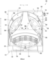
- FIG. 1 provides a front view of a gardening appliance 100 according to an exemplary embodiment of the present subject matter.
- gardening appliance 100 may be used as an indoor garden center for growing plants. It should be appreciated that the embodiments described herein are intended only for explaining aspects of the present subject matter. Variations and modifications may be made to gardening appliance 100 while remaining within the scope of the present subject matter.
- Gardening appliance 100 includes a housing or cabinet 102 that extends between a top 104 and a bottom 106 along a vertical direction V, between a first side 108 and a second side 110 along a lateral direction L, and between a front side 112 and a rear side 114 along a transverse direction T.
- Each of the vertical direction V, lateral direction L, and transverse direction T are mutually perpendicular to one another and form an orthogonal direction system.
- Gardening appliance 100 may include an insulated liner 120 positioned within cabinet 102.
- Liner 120 may at least partially define a temperature controlled, referred to herein generally as a grow chamber 122, within which plants 124 may be grown.
- a temperature controlled referred to herein generally as a grow chamber 122
- plants 124 may be grown.
- growing plants 124 it should be appreciated that other organisms or living things may be grown or stored in gardening appliance 100.
- algae, fungi e.g., including mushrooms
- other living organisms may be grown or stored in gardening appliance 100.
- the specific application described herein is not intended to limit the scope of the present subject matter.
- Cabinet 102 may define a substantially enclosed back region or portion 130.
- cabinet 102 and liner 120 may define a front opening, referred to herein as front display opening 132, through which a user of gardening appliance 100 may access grow chamber 122, e.g., for harvesting, planting, pruning, or otherwise interacting with plants 124.
- enclosed back portion 130 may be defined as a portion of liner 120 that defines grow chamber 122 proximate rear side 114 of cabinet 102.
- front display opening 132 may generally be positioned proximate or coincide with front side 112 of cabinet 102.
- Gardening appliance 100 may further include one or more doors 134 that are rotatably mounted to cabinet 102 for providing selective access to grow chamber 122.
- FIG. 1 illustrates doors 134 in the closed position such that they may help insulate grow chamber 122.
- FIG. 2 illustrates doors 134 in the open positioned for accessing grow chamber 122 and plants 124 stored therein.
- Doors 134 may further include a transparent window 136 through which a user may observe plants 124 without opening doors 134.
- doors 134 are illustrated as being rectangular and being mounted on front side 112 of cabinet 102 in FIGS. 1 and 2 , it should be appreciated that according to alternative embodiments, doors 134 may have different shapes, mounting locations, etc. For example, doors 134 may be curved, may be formed entirely from glass, etc. In addition, doors 134 may have integral features for controlling light passing into and/or out of grow chamber 122, such as internal louvers, tinting, UV treatments, polarization, etc. One skilled in the art will appreciate that other chamber and door configurations are possible and within the scope of the present invention.
- cabinet 102 further defines a drawer 138 positioned proximate bottom 106 of cabinet 102 and being slidably mounted to cabinet for providing convenient storage for plant nutrients, system accessories, water filters, etc.
- a mechanical compartment 140 for receipt of an environmental control system including a sealed system for regulating the temperature within grow chamber 122, as described in more detail below.
- FIG. 3 provides a schematic view of certain components of an environmental control system 148 that may be used to regulate a temperature within grow chamber 122.
- environmental control system 148 may include a sealed system 150, a duct system 160, and a hydration system 270, or any other suitable components or subsystems for regulating an environment within grow chamber 122, e.g., for facilitating improved or regulated growth of plants 124 positioned therein.
- FIG. 3 illustrates sealed system 150 within mechanical compartment 140.
- sealed system 150 may include additional or alternative components, different ducting configurations, etc.
- sealed system 150 includes a compressor 152, a first heat exchanger or evaporator 154 and a second heat exchanger or condenser 156.
- compressor 152 is generally operable to circulate or urge a flow of refrigerant through sealed system 150, which may include various conduits which may be utilized to flow refrigerant between the various components of sealed system 150.
- evaporator 154 and condenser 156 may be between and in fluid communication with each other and compressor 152.
- refrigerant flows from evaporator 154 and to compressor 152, and compressor 152 is generally configured to direct compressed refrigerant from compressor 152 to condenser 156.
- refrigerant may exit evaporator 154 as a fluid in the form of a superheated vapor.
- compressor 152 Upon exiting evaporator 154, the refrigerant may enter compressor 152, which is operable to compress the refrigerant. Accordingly, the pressure and temperature of the refrigerant may be increased in compressor 152 such that the refrigerant becomes a more superheated vapor.
- Condenser 156 is disposed downstream of compressor 152 and is operable to reject heat from the refrigerant.
- the superheated vapor from compressor 152 may enter condenser 156 and transfer energy to air surrounding condenser 156 (e.g., to create a flow of heated air).
- the refrigerant condenses into a saturated liquid and/or liquid vapor mixture.
- a condenser fan (not shown) may be positioned adjacent condenser 156 and may facilitate or urge the flow of heated air across the coils of condenser 156 (e.g., from ambient atmosphere) in order to facilitate heat transfer.
- variable electronic expansion valve 158 may be further provided to regulate refrigerant expansion.
- variable electronic expansion valve 158 may generally expand the refrigerant, lowering the pressure and temperature thereof.
- refrigerant may exit condenser 156 in the form of high liquid quality/saturated liquid vapor mixture and travel through variable electronic expansion valve 158 before flowing through evaporator 154.
- Variable electronic expansion valve 158 is generally configured to be adjustable, e.g., such that the flow of refrigerant (e.g., volumetric flow rate in milliliters per second) through variable electronic expansion valve 158 may be selectively varied or adjusted.
- Evaporator 154 is disposed downstream of variable electronic expansion valve 158 and is operable to heat refrigerant within evaporator 154, e.g., by absorbing thermal energy from air surrounding the evaporator (e.g., to create a flow of cooled air).
- the liquid or liquid vapor mixture refrigerant from variable electronic expansion valve 158 may enter evaporator 154.
- the refrigerant from variable electronic expansion valve 158 receives energy from the flow of cooled air and vaporizes into superheated vapor and/or high quality vapor mixture.
- An air handler or evaporator fan (not shown) is positioned adjacent evaporator 154 and may facilitate or urge the flow of cooled air across evaporator 154 in order to facilitate heat transfer. From evaporator 154, refrigerant may return to compressor 152 and the vapor-compression cycle may continue.
- environmental control system 148 includes a sealed system 150 for providing a flow of heated air or a flow cooled air throughout grow chamber 122 as needed.
- environmental control system 148 includes a duct system 160 for directing the flow of temperature regulated air, identified herein simply as flow of air 162 (see, e.g., FIG. 3 ).
- an evaporator fan can generate a flow of cooled air as the air passes over evaporator 154 and a condenser fan can generate a flow of heated air as the air passes over condenser 156.
- environmental control system 148 may generally include a plurality of ducts, dampers, diverter assemblies, and/or air handlers to facilitate operation in a cooling mode, in a heating mode, in both a heating and cooling mode, or any other mode suitable for regulating the environment within grow chamber 122.
- duct system 160 may vary in complexity and may regulate the flows of air from sealed system 150 in any suitable arrangement through any suitable portion of grow chamber 122.
- Gardening appliance 100 may include a control panel 170.
- Control panel 170 includes one or more input selectors 172, such as e.g., knobs, buttons, push buttons, touchscreen interfaces, etc.
- input selectors 172 may be used to specify or set various settings of gardening appliance 100, such as e.g., settings associated with operation of sealed system 150.
- Input selectors 172 may be in communication with a processing device or controller 174. Control signals generated in or by controller 174 operate gardening appliance 100 in response to input selectors 172.
- control panel 170 may include a display 176, such as an indicator light or a screen. Display 176 is communicatively coupled with controller 174 and may display information in response to signals from controller 174. Further, as will be described herein, controller 174 may be communicatively coupled with other components of gardening appliance 100, such as e.g., one or more sensors, motors, or other components.
- processing device or “controller” may refer to one or more microprocessors or semiconductor devices and is not restricted necessarily to a single element.
- the processing device can be programmed to operate gardening appliance 100.
- the processing device may include, or be associated with, one or more memory elements (e.g., non-transitory storage media).
- the memory elements include electrically erasable, programmable read only memory (EEPROM).
- EEPROM electrically erasable, programmable read only memory
- the memory elements can store information accessible processing device, including instructions that can be executed by processing device.
- the instructions can be software or any set of instructions and/or data that when executed by the processing device, cause the processing device to perform operations.
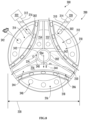
- gardening appliance 100 generally includes a rotatable carousel, referred to herein as a grow module 200 that is mounted within liner 120, e.g., such that it is within grow chamber 122.
- grow module 200 includes a central hub 202 that extends along and is rotatable about a central axis 204.
- central axis 204 is parallel to the vertical direction V.
- central axis 204 could alternatively extend in any suitable direction, e.g., such as the horizontal direction.
- grow module 200 generally defines an axial direction, i.e., parallel to central axis 204, a radial direction R that extends perpendicular to central axis 204, and a circumferential direction C that extends around central axis 204 (e.g. in a plane perpendicular to central axis 204).
- Grow module 200 may further include a plurality of partitions 206 that extend from central hub 202 substantially along the radial direction R.
- grow module 200 defines a plurality of chambers, referred to herein generally by reference numeral 210, by dividing or partitioning grow chamber 122.
- grow module 200 includes three partitions 206 to define a first chamber 212, a second chamber 214, and a third chamber 216, which are circumferentially spaced relative to each other.
- the plurality of chambers 210 define substantially separate and distinct growing environments, e.g., for growing plants 124 having different growth needs.
- partitions 206 may extend from central hub 202 to a location immediately adjacent liner 120. Although partitions 206 are described as extending along the radial direction, it should be appreciated that they need not be entirely radially extending. For example, according to the illustrated embodiment, the distal ends of each partition is joined with an adjacent partition using an arcuate wall 218, which is generally used to support plants 124.
- grow module 200 may define a grow module diameter 220 (e.g., defined by its substantially circular footprint formed in a horizontal plane).
- enclosed back portion 130 of liner 120 may be substantially cylindrical and may define a liner diameter 222.
- liner diameter 222 may be substantially equal to or slightly larger than grow module diameter 220.
- gardening appliance 100 may further include a motor 230 or another suitable driving element or device for selectively rotating grow module 200 during operation of gardening appliance 100.
- motor 230 is positioned below grow module 200, e.g., within mechanical compartment 140, and is operably coupled to grow module 200 along central axis 204 for rotating grow module 200.
- motor may refer to any suitable drive motor and/or transmission assembly for rotating grow module 200.
- motor 230 may be a brushless DC electric motor, a stepper motor, or any other suitable type or configuration of motor.
- motor 230 may be an AC motor, an induction motor, a permanent magnet synchronous motor, or any other suitable type of AC motor.
- motor 230 may include any suitable transmission assemblies, clutch mechanisms, or other components.
- motor 230 may be operably coupled to controller 174, which is programmed to rotate grow module 200 according to predetermined operating cycles, based on user inputs (e.g. via touch buttons 172), etc.
- controller 174 may be communicatively coupled to one or more sensors, such as temperature or humidity sensors, positioned within the various chambers 210 for measuring temperatures and/or humidity, respectively. Controller 174 may then operate motor 230 in order to maintain desired environmental conditions for each of the respective chambers 210.
- gardening appliance 100 includes features for providing certain locations of gardening appliance 100 with light, temperature control, proper moisture, nutrients, and other requirements for suitable plant growth. Motor 230 may be used to position specific chambers 210 where needed to receive such growth requirements.
- controller 174 may operate motor 230 to index grow module 200 sequentially through a number of preselected positions. More specifically, motor 230 may rotate grow module 200 in a counterclockwise direction (e.g. when viewed from a top of grow module 200) in 120° increments to move chambers 210 between sealed positions and display positions.
- a chamber 210 is considered to be in a "sealed position" when that chamber 210 is substantially sealed between grow module 200 (i.e., central hub 202 and adjacent partitions 206) and liner 120.
- a chamber 210 is considered to be in a "display position" when that chamber 210 is at least partially exposed to front display opening 132, such that a user may access plants 124 positioned within that chamber 210.
- first chamber 212 and second chamber 214 are both in a sealed position, whereas third chamber 216 is in a display position.
- motor 230 rotates grow module 200 by 120 degrees in the counterclockwise direction, second chamber 214 will enter the display position, while first chamber 212 and third chamber 216 will be in the sealed positions. Motor 230 may continue to rotate grow module 200 in such increments to cycle grow chambers 210 between these sealed and display positions.
- grow module 200 defines a plurality of apertures 240 which are generally configured for receiving plant pods 242 into an internal root chamber 244.
- Plant pods 242 generally contain seedlings or other material for growing plants positioned within a mesh or other support structure through which roots of plants 124 may grow within grow module 200.
- a user may insert a portion of plant pod 242 (e.g., a seed end or root end 246) having the desired seeds through one of the plurality of apertures 240 into root chamber 244.
- a plant end 248 of the plant pod 242 may remain within grow chamber 210 such that plants 124 may grow from grow module 200 such that they are accessible by a user.
- grow module 200 defines root chamber 244, e.g., within at least one of central hub 202 and the plurality of partitions 206.
- root chamber 244 e.g., within at least one of central hub 202 and the plurality of partitions 206.
- water and other nutrients may be supplied to the root end 246 of plant pods 242 within root chamber 244.
- apertures 240 may be covered by a flat flapper seal (not shown) to prevent water from escaping root chamber 244 when no plant pod 242 is installed.
- grow module 200 may further include an internal divider 250 that is positioned within root chamber 244 to divide root chamber 244 into a plurality of root chambers, each of the plurality of root chambers being in fluid communication with one of the plurality of grow chambers 210 through the plurality of apertures 240. More specifically, according to the illustrated embodiment, internal divider 250 may divide root chamber 244 into a first root chamber 252, a second root chamber 254, and a third root chamber 256.
- first root chamber 252 may provide water and nutrients to plants 124 positioned in the first grow chamber 212
- second root chamber 254 may provide water and nutrients to plants 124 positioned in the second grow chamber 214
- third root chamber 256 may provide water and nutrients to plants 124 positioned in the third grow chamber 216.
- environmental control system 148 may control the temperature and/or humidity of each of the plurality of chambers 212-216 and the plurality of root chambers 252-256 independently of each other.
- Environmental control system 148 may further include a hydration system 270 which is generally configured for providing water to plants 124 to support their growth.
- hydration system 270 generally includes a water supply 272 and misting device 274 (e.g., such as a fine mist spray nozzle or nozzles).
- water supply 272 may be a reservoir containing water (e.g., distilled water) or may be a direct connection municipal water supply.
- Misting device 274 may be positioned at a bottom of root chamber 244 and may be configured for charging root chamber 244 with mist for hydrating the roots of plants 124.
- misting devices 274 may pass through central hub 204 along the vertical direction V and periodically include a nozzle for spraying a mist or water into root chamber 244.
- hydration system 270 may alternatively include a plurality of misting devices 274, e.g., all coupled to water supply 272, but being selectively operated to charge each of first root chamber 252, second root chamber 254, and third root chamber 256 independently of each other.
- the term "hydration cycle" is intended generally to refer to the time period or periods during which hydration system 270 is providing liquid into gardening appliance 100, e.g., directly into root chamber 244.
- environmental control system 148 described above is generally configured for regulating the temperature and humidity (e.g., or some other suitable water level quantity or measurement) within one or all of the plurality of chambers 210 and/or root chambers 252-256 independently of each other. In this manner, a versatile and desirable growing environment may be obtained for each and every chamber 210.
- temperature and humidity e.g., or some other suitable water level quantity or measurement
- gardening appliance 100 may further include a light assembly 280 which is generally configured for providing light into selected grow chambers 210 to facilitate photosynthesis and growth of plants 124.
- light assembly 280 may include a plurality of light sources 282 stacked in an array, e.g., extending along the vertical direction V.
- light sources 282 may be mounted directly to liner 120 within grow chamber 122, or may alternatively be positioned behind liner 120 such that light is projected through a transparent window or light pipe into grow chamber 122.
- the position, configuration, and type of light sources 282 described herein are not intended to limit the scope of the present subject matter in any manner.
- Light sources 282 may be provided as any suitable number, type, position, and configuration of electrical light source(s), using any suitable light technology and illuminating in any suitable color.
- light source 282 includes one or more light emitting diodes (LEDs), which may each illuminate in a single color (e.g., white LEDs), or which may each illuminate in multiple colors (e.g., multi-color or RGB LEDs) depending on the control signal from controller 174.
- LEDs light emitting diodes
- light sources 282 may include any other suitable traditional light bulbs or sources, such as halogen bulbs, fluorescent bulbs, incandescent bulbs, glow bars, a fiber light source, etc.
- light generated from light assembly 280 may result in light pollution within a room where gardening appliance 100 is located. Therefore, aspects of the present subject matter are directed to features for reducing light pollution, or to the blocking of light from light sources 282 through front display opening 132.
- light assembly 280 is positioned only within the enclosed back portion 130 of liner 120 such that only grow chambers 210 which are in a sealed position are exposed to light from light sources 282.
- grow module 200 acts as a physical partition between light assemblies 280 and front display opening 132. In this manner, as illustrated in FIG. 5 , no light may pass from first chamber 212 or second chamber 214 through grow module 200 and out front display opening 132.
- a single light assembly may be used to reduce costs, whereby only a single grow chamber 210 will be lit at a single time.
- gardening appliance 100 may be a simplified to a two-chamber embodiment with a square liner 120 and a grow module 200 having two partitions 206 extending from opposite sides of central hub 202 to define a first grow chamber and a second grow chamber.
- the first chamber may alternate between the sealed position (e.g., facing rear side 114 of cabinet 102) and the display position (e.g., facing front side 112 of cabinet 102).
- the same rotation will move the second chamber from the display position to the sealed position.
- gardening appliance 100 may include a three chamber grow module 200 but may have a modified cabinet 102 such that front display opening 132 is wider and two of the three grow chambers 210 are displayed at a single time.
- first chamber 212 may be in the sealed position
- second chamber 214 and third chamber 216 may be in the display positions.
- grow module 200 is rotated counterclockwise, first chamber 212 is moved into the display position and third chamber 216 is moved into the sealed position.
- environmental control system 148 includes an air circulation system 300 that is generally configured for providing a flow of air (e.g., identified generally herein by reference numeral 302) into and throughout gardening appliance 100, e.g., such as directly into root chamber 244.
- a flow of air e.g., identified generally herein by reference numeral 302
- the flow of air 302 may include any suitable combination of gases at any suitable concentrations.
- air circulation system 300 includes a supply duct 310 and an outlet duct 312 that are in fluid communication with grow chamber 122. More specifically, according to the illustrated embodiment, supply duct 310 and outlet duct 312 are directly fluidly coupled to a bottom of root chamber 244. In this manner, air circulation system 300 may circulate flow of air 302 through root chamber 244 using ducts 310, 312 in order to maintain desired temperatures within gardening appliance 100. It should be appreciated that air circulation system 300 may include any suitable number, type, position, and configuration of flow regulating devices to control the flow of air 302.
- air circulation system 300 includes a supply damper 314 that is operably coupled with supply duct 310 for regulating the flow of air 302 through supply duct 310.
- air circulation system 300 includes an outlet damper 316 that is operably coupled to outlet duct 312 for regulating the flow of air 302 through outlet duct 312.
- Air circulation assembly 300 may further include a fan assembly or a circulation fan 320 that is in fluid communication with grow chamber 122 through one or both of supply duct 310 and outlet duct 312.
- controller 174 may selectively operate circulation fan 320 to circulate the flow of air 302 throughout root chamber 244.
- the circulation fan 320 may be any flow regulating device that is configured for recirculating or urging a flow of air.
- the circulation fan 320 may include one or more axial fans, centrifugal fans, etc.
- the circulation fan 320 may be positioned at any suitable location on or in ducts 310, 312 or otherwise in fluid communication with grow chamber 122.
- outlet duct 312 fluidly couples root chamber 244 to an ambient environment 322, e.g., for discharging the flow of air 302.
- air circulation system 300 may include a duct system and flow regulating features for recirculating, filtering, treating, and/or reusing the flow of air 302.
- gardening appliance 100 may include one or more devices or subsystems for monitoring moisture levels or water content within grow chamber 122.
- gardening appliance 100 includes a water detection device 340 that is positioned within root chamber 244 for measuring a moisture level within root chamber 244.
- water detection device 340 comprises one or more optical sensors 342 positioned at different locations within root chamber 244.
- optical sensors 342 may transmit and receive a beam of light energy 344 in order to determine the amount of water within root chamber 244, e.g., based on distortion of the beam of light energy 344.
- an optical sensor is described herein, it should be appreciated that according to alternative embodiments, any suitable humidity sensors or other moisture detection systems and methods may be used while remaining within the scope of the present subject matter.
- exemplary method 400 of operating a gardening appliance will be described. Although the discussion below refers to the exemplary method 400 of operating gardening appliance 100, one skilled in the art will appreciate that the exemplary method 400 is applicable to the operation of a variety of other gardening appliances or for use in any suitable application. In exemplary embodiments, the various method steps as disclosed herein may be performed by controller 174 or a separate, dedicated controller.
- hydration system 270 provides a mist or flow of liquid into root chamber 244. After the spray nozzles finish discharging water, small droplets of water gently flow through root chamber 244. These droplets are slowly deposited onto the roots and walls to hydrate the roots of plants 124. However, if air from air circulation system 300 is provided into root chamber 244 during these periods of high droplet density, the droplets may fail to reach the roots of plants 124 effectively.
- FIG. 9 illustrates an exemplary hydration cycle of gardening appliance 100, with a measure of the amount of water in the air illustrated by reference numeral 350.
- hydration system 270 provides a flow of water to nozzles or misting devices within root chamber 244.
- the droplet density or water level percentage profile 350 may increase quickly until an end time 354 of the hydration cycle.
- the water level 350 slowly decays. Therefore, as explained below, aspects of the present subject matter are directed to a system and method for regulating airflow in order to reduce negative effects on the hydration cycle.
- method 400 includes, at step 410, operating an air circulation system to urge the flow of air through a root chamber of a gardening appliance.
- air circulation system 300 may urge the flow of air 302 through root chamber 244, e.g., to maintain desired temperatures within root chamber 244.
- method 400 may generally include stopping the flow of air during the hydration cycle. The amount of time that the flow of air is stopped may depend in part on the water levels 350 or may be time-based, e.g., such that air circulation system 300 is operated based at least in part on the operation of hydration system 270 (e.g., based on start and stop times of the hydration system 270).
- method 400 may include stopping the flow of air slightly before the start of the hydration cycle and preventing the flow of air for a certain duration after the end of the hydration cycle.
- air circulation system 300 may include any suitable means for stopping or slowing the flow of air 302.
- the flow of air 302 may be stopped by closing supply damper 314, closing outlet damper 316, and/or stopping circulation fan 320.
- step 420 includes stopping the flow of air prior to commencement of a hydration cycle.
- the air stop time 356 of the flow of air may be a first predetermined amount of time 358 before start time 352 of the hydration cycle.
- Step 430 includes implementing the hydration cycle by using a hydration system to provide a flow of liquid into the root chamber.
- Step 440 may include preventing the flow of air until after the hydration cycle has ended.
- the flow of air may not commence until an air start time 360, which may be after a second predetermined amount of time 362 has passed since the end time 354 of the hydration cycle.
- stopping the flow of air at 420 and preventing the flow of air at 440 may include determining a start time and an end time of a hydration cycle. From the start time and the end time of the hydration cycle, an air stop time 356 and an air start time 360 may be determined. It should be appreciated that during the time between air stop time 356 and air start time 360, air circulation system 300 prevents the flow of air 302 through root chamber 244. Outside of this no flow period, air may or may not be supplied depending on commands of an environmental control system 148, e.g., based on the temperature within root chamber 244.
- the first predetermined amount of time 358 and the second predetermined amount of time 362 may be set by the manufacturer, selected by the user, may be determined empirically, or may be calculated using controller 174. In addition, these times 358, 362 may vary depending on a variety of factors, such as nozzle flow rates, chamber humidity, air flow rates, or any other suitable factors.
- the first predetermined amount of time 358 is generally selected to be a suitable amount of time to permit air currents within grow chamber 244 to dissipate below a threshold.
- the first predetermined amount of time 358 may be between about 0.1 seconds and 20 seconds, between about 0.5 seconds and 10 seconds, between about 1 second and 4 seconds, or about 3 seconds.
- the second predetermined amount of time 362 may be determined based at least in part on the decay of water level 350, e.g., how long it takes water level 350 to drop below a suitable threshold.
- the second predetermined amount of time 362 may be between about 1 second and 60 seconds, between about 5 seconds and 30 seconds, between about 10 seconds and 20 seconds, or about 15 seconds.
- stopping the flow of air and preventing the flow of air may include regulating airflow based on a moisture level or water level within root chamber 244.
- controller 174 may measure a moisture level (e.g., water level 350) using water detection device 340.
- the air stop time 356 and/or the air start time 360 may be determined based on this water level 350.
- the water level threshold may vary according to the particular application while remaining within the scope of the present subject matter.
- other factors and considerations may affect the air stop time 356 and the air start time 360.
- FIG. 10 depicts steps performed in a particular order for purposes of illustration and discussion. Those of ordinary skill in the art, using the disclosures provided herein, will understand that the steps of any of the methods discussed herein can be adapted, rearranged, expanded, omitted, or modified in various ways without deviating from the scope of the present disclosure. Moreover, although aspects of method 400 are explained using gardening appliance 100 as an example, it should be appreciated that these methods may be applied to the operation of any suitable gardening appliance.
Landscapes
- Life Sciences & Earth Sciences (AREA)
- Environmental Sciences (AREA)
- Engineering & Computer Science (AREA)
- Water Supply & Treatment (AREA)
- Cultivation Of Plants (AREA)
- Greenhouses (AREA)
Applications Claiming Priority (2)
| Application Number | Priority Date | Filing Date | Title |
|---|---|---|---|
| US16/927,130 US11559008B2 (en) | 2020-07-13 | 2020-07-13 | Hydration system for an indoor garden center and a method of operating the same |
| PCT/CN2021/105012 WO2022012389A1 (fr) | 2020-07-13 | 2021-07-07 | Système de remplissage d'eau pour centre de jardin d'intérieur et son procédé de fonctionnement |
Publications (2)
| Publication Number | Publication Date |
|---|---|
| EP4179871A1 true EP4179871A1 (fr) | 2023-05-17 |
| EP4179871A4 EP4179871A4 (fr) | 2024-01-03 |
Family
ID=79171635
Family Applications (1)
| Application Number | Title | Priority Date | Filing Date |
|---|---|---|---|
| EP21841305.2A Pending EP4179871A4 (fr) | 2020-07-13 | 2021-07-07 | Système de remplissage d'eau pour centre de jardin d'intérieur et son procédé de fonctionnement |
Country Status (5)
| Country | Link |
|---|---|
| US (1) | US11559008B2 (fr) |
| EP (1) | EP4179871A4 (fr) |
| JP (1) | JP7522294B2 (fr) |
| CN (1) | CN115802885B (fr) |
| WO (1) | WO2022012389A1 (fr) |
Families Citing this family (1)
| Publication number | Priority date | Publication date | Assignee | Title |
|---|---|---|---|---|
| US11696534B2 (en) * | 2021-07-21 | 2023-07-11 | Haier Us Appliance Solutions, Inc. | Climate control system for an indoor garden center |
Family Cites Families (34)
| Publication number | Priority date | Publication date | Assignee | Title |
|---|---|---|---|---|
| US5749170A (en) * | 1995-06-30 | 1998-05-12 | Fulta Electric Machinery Co., Ltd. | Automatic water supply device |
| US20020116870A1 (en) * | 2002-03-05 | 2002-08-29 | Chen Carl Wan-Cheng | Automatic houseplant watering apparatus for homes and offices |
| US20070267515A1 (en) * | 2006-05-18 | 2007-11-22 | Sargent Ronald J | Apparatus for monitoring and regulating soil moisture |
| JP2008125432A (ja) | 2006-11-21 | 2008-06-05 | Fuji Work:Kk | 緑化基盤、この緑化基盤を用いた水分センサーの設置方法並びに緑化基盤の潅水システム |
| JP4893502B2 (ja) | 2007-06-28 | 2012-03-07 | Mkvドリーム株式会社 | 多段式植物育成装置の育成棚各段への加湿空気流供給システム |
| US20090293357A1 (en) | 2008-05-27 | 2009-12-03 | Ross Vickers | Aeroponic atomizer for horticulture |
| CA2736254A1 (fr) | 2008-09-19 | 2010-03-25 | Martin Mittelmark | Dispositif de micro-irrigation, systeme et procede de purification de l'air interieur par des plantes et bioregeneration par filtre de purification |
| KR20110051917A (ko) * | 2009-11-11 | 2011-05-18 | (주)유스텍 | 송풍수단을 갖는 케비넷형 식물 재배기 |
| JP6331248B2 (ja) * | 2012-01-16 | 2018-05-30 | パナソニックIpマネジメント株式会社 | 植物育成装置 |
| CN102948360A (zh) * | 2012-03-22 | 2013-03-06 | 中国林业科学研究院华北林业实验中心 | 一种立体自控植物气雾培养装置 |
| CO7150305A1 (es) | 2013-05-29 | 2014-12-29 | Univ Nac De Colombia | Dispositivo y método para la obtención de cultivos sin tierra |
| JP5639701B1 (ja) | 2013-09-12 | 2014-12-10 | パナソニック株式会社 | 水耕栽培装置及び水耕栽培方法 |
| CN104654720A (zh) * | 2013-11-18 | 2015-05-27 | 明廷超 | 一种可种菜的冰箱 |
| PL2923561T3 (pl) | 2014-03-28 | 2018-04-30 | Plantui Oy | Hydroponiczny sposób uprawy ogrodniczej w pomieszczeniach |
| US9807949B2 (en) | 2014-08-15 | 2017-11-07 | John W. Hamlin | Root environment control system and method |
| US20160128288A1 (en) | 2014-11-07 | 2016-05-12 | Ohneka Farms LLC | Self-watering, self-lighting hydroponic system |
| WO2016164652A1 (fr) | 2015-04-09 | 2016-10-13 | Growx Inc. | Systèmes, procédés et dispositifs pour ensemble de diodes électroluminescentes et appareil d'horticulture |
| CN105165591B (zh) * | 2015-08-24 | 2018-08-24 | 桂林国宏裕民科技有限公司 | 一种柜式芽苗菜培育装置 |
| WO2017059172A1 (fr) | 2015-10-01 | 2017-04-06 | United Electrical Systems Llc | Temporisateur intelligent pour réfrigérateurs et appareils similaires |
| JP6664613B2 (ja) | 2016-01-18 | 2020-03-13 | 本多電子株式会社 | 垂直型の超音波霧化栽培装置 |
| CN106376374A (zh) * | 2016-08-29 | 2017-02-08 | 深圳前海弘稼科技有限公司 | 一种用于种植箱的自动降温补氧方法和种植箱 |
| KR102726844B1 (ko) | 2016-10-07 | 2024-11-05 | 스캇 매시 | 식물 재배 장치 및 방법 |
| US20180125016A1 (en) * | 2016-11-08 | 2018-05-10 | Stephen A. Dufresne | Multi-level horizontal air flow distribution system |
| US10668493B2 (en) * | 2017-03-16 | 2020-06-02 | Boulind, Inc. | Spray system with dynamically configurable droplet sizes |
| CN107166550B (zh) * | 2017-05-23 | 2019-12-10 | 南京哈恩科技有限公司 | 室内环境调节设备 |
| US11206774B2 (en) * | 2018-08-02 | 2021-12-28 | Pod Farms, LLC | Vertical hydroponic growing system and method |
| WO2020034009A1 (fr) * | 2018-08-17 | 2020-02-20 | Manski Pty Ltd | Système agricole commandé par ordinateur |
| CN112867393A (zh) * | 2018-08-20 | 2021-05-28 | 合利博尼克斯有限责任公司 | 旋转式气培设备和方法 |
| US20200110933A1 (en) * | 2018-10-05 | 2020-04-09 | AI Gronomy LLC | System and method for automated plant growth |
| JP2020065522A (ja) | 2018-10-28 | 2020-04-30 | 株式会社恵葉&菜健康野菜 | ミスト型水耕栽培システム、および、水流噴射型水耕栽培システム、および水耕栽培方法 |
| CN109673501A (zh) * | 2019-01-31 | 2019-04-26 | 湖南农业大学 | 一种超声波智能气雾栽培装置 |
| US11147395B2 (en) * | 2019-05-08 | 2021-10-19 | Haier Us Appliance Solutions, Inc. | Indoor garden center with rotating compartments |
| KR102121023B1 (ko) * | 2019-06-05 | 2020-06-09 | 한긍우 | 식물재배용기를 이용한 재배 시스템 |
| KR102102831B1 (ko) * | 2019-10-30 | 2020-04-22 | (주)엠티이에스 | 실내 정원을 이용한 공기조화시스템 |
-
2020
- 2020-07-13 US US16/927,130 patent/US11559008B2/en active Active
-
2021
- 2021-07-07 JP JP2023502769A patent/JP7522294B2/ja active Active
- 2021-07-07 WO PCT/CN2021/105012 patent/WO2022012389A1/fr not_active Ceased
- 2021-07-07 EP EP21841305.2A patent/EP4179871A4/fr active Pending
- 2021-07-07 CN CN202180048151.2A patent/CN115802885B/zh active Active
Also Published As
| Publication number | Publication date |
|---|---|
| EP4179871A4 (fr) | 2024-01-03 |
| JP2023537216A (ja) | 2023-08-31 |
| CN115802885B (zh) | 2024-09-10 |
| CN115802885A (zh) | 2023-03-14 |
| WO2022012389A1 (fr) | 2022-01-20 |
| JP7522294B2 (ja) | 2024-07-24 |
| US20220007593A1 (en) | 2022-01-13 |
| US11559008B2 (en) | 2023-01-24 |
Similar Documents
| Publication | Publication Date | Title |
|---|---|---|
| US11147395B2 (en) | Indoor garden center with rotating compartments | |
| US11240974B2 (en) | Indoor garden center with a resilient sealing element | |
| US20210084828A1 (en) | System and method for suggestive lighting in an indoor gardening appliance | |
| US20220174890A1 (en) | Method of operating a lighting system for an indoor garden center | |
| US20210105955A1 (en) | Atmosphere control system for an indoor gardening appliance | |
| US20210084845A1 (en) | Nutrient dosing system for an indoor gardening appliance | |
| US11766000B2 (en) | Gas sensing assembly for an indoor garden center | |
| US11343976B2 (en) | Indoor garden center with a plant pod detection system | |
| US11160218B2 (en) | Indoor garden center with rotating compartments and environmental control | |
| US11457580B2 (en) | Indoor garden center with a nutrient cartridge system | |
| US11980145B2 (en) | Drive assembly for rotating a grow tower in an indoor garden center | |
| US11533859B2 (en) | Hydration system for an indoor gardening appliance | |
| US11503774B2 (en) | Grow lighting profiles for indoor garden center | |
| US11723326B2 (en) | Pod mounting interface for an indoor garden center | |
| US11559008B2 (en) | Hydration system for an indoor garden center and a method of operating the same | |
| US11503776B2 (en) | Method of operating a sealed system for an indoor garden center | |
| US20220007595A1 (en) | Hydration system for an indoor gardening appliance | |
| US11240968B2 (en) | Pollen distribution system for an indoor gardening appliance | |
| US11696534B2 (en) | Climate control system for an indoor garden center | |
| US11528851B2 (en) | Indoor garden center with a moisture management system | |
| US12114626B2 (en) | Indoor garden center environmental control system | |
| US20220007664A1 (en) | Indoor garden center with a ripening control system | |
| US20230397544A1 (en) | System and method for thermal radiation management for gardening appliance | |
| US20230172127A1 (en) | Plant growing appliance with a camera |
Legal Events
| Date | Code | Title | Description |
|---|---|---|---|
| STAA | Information on the status of an ep patent application or granted ep patent |
Free format text: STATUS: THE INTERNATIONAL PUBLICATION HAS BEEN MADE |
|
| PUAI | Public reference made under article 153(3) epc to a published international application that has entered the european phase |
Free format text: ORIGINAL CODE: 0009012 |
|
| STAA | Information on the status of an ep patent application or granted ep patent |
Free format text: STATUS: REQUEST FOR EXAMINATION WAS MADE |
|
| 17P | Request for examination filed |
Effective date: 20230113 |
|
| AK | Designated contracting states |
Kind code of ref document: A1 Designated state(s): AL AT BE BG CH CY CZ DE DK EE ES FI FR GB GR HR HU IE IS IT LI LT LU LV MC MK MT NL NO PL PT RO RS SE SI SK SM TR |
|
| DAV | Request for validation of the european patent (deleted) | ||
| DAX | Request for extension of the european patent (deleted) | ||
| A4 | Supplementary search report drawn up and despatched |
Effective date: 20231206 |
|
| RIC1 | Information provided on ipc code assigned before grant |
Ipc: A01G 9/00 20180101ALI20231130BHEP Ipc: A01G 9/24 20060101ALI20231130BHEP Ipc: A01G 13/02 20060101ALI20231130BHEP Ipc: A01G 7/04 20060101ALI20231130BHEP Ipc: A01G 9/02 20180101ALI20231130BHEP Ipc: A01G 31/02 20060101AFI20231130BHEP |