EP4179943B1 - Machine de nettoyage de sol guidée à la main - Google Patents
Machine de nettoyage de sol guidée à la main Download PDFInfo
- Publication number
- EP4179943B1 EP4179943B1 EP22206011.3A EP22206011A EP4179943B1 EP 4179943 B1 EP4179943 B1 EP 4179943B1 EP 22206011 A EP22206011 A EP 22206011A EP 4179943 B1 EP4179943 B1 EP 4179943B1
- Authority
- EP
- European Patent Office
- Prior art keywords
- joint
- base
- joint element
- envelope
- cleaning machine
- Prior art date
- Legal status (The legal status is an assumption and is not a legal conclusion. Google has not performed a legal analysis and makes no representation as to the accuracy of the status listed.)
- Active
Links
Images


Classifications
-
- A—HUMAN NECESSITIES
- A47—FURNITURE; DOMESTIC ARTICLES OR APPLIANCES; COFFEE MILLS; SPICE MILLS; SUCTION CLEANERS IN GENERAL
- A47L—DOMESTIC WASHING OR CLEANING; SUCTION CLEANERS IN GENERAL
- A47L11/00—Machines for cleaning floors, carpets, furniture, walls, or wall coverings
- A47L11/29—Floor-scrubbing machines characterised by means for taking-up dirty liquid
- A47L11/30—Floor-scrubbing machines characterised by means for taking-up dirty liquid by suction
- A47L11/302—Floor-scrubbing machines characterised by means for taking-up dirty liquid by suction having rotary tools
- A47L11/305—Floor-scrubbing machines characterised by means for taking-up dirty liquid by suction having rotary tools the tools being disc brushes
-
- A—HUMAN NECESSITIES
- A47—FURNITURE; DOMESTIC ARTICLES OR APPLIANCES; COFFEE MILLS; SPICE MILLS; SUCTION CLEANERS IN GENERAL
- A47L—DOMESTIC WASHING OR CLEANING; SUCTION CLEANERS IN GENERAL
- A47L11/00—Machines for cleaning floors, carpets, furniture, walls, or wall coverings
-
- A—HUMAN NECESSITIES
- A47—FURNITURE; DOMESTIC ARTICLES OR APPLIANCES; COFFEE MILLS; SPICE MILLS; SUCTION CLEANERS IN GENERAL
- A47L—DOMESTIC WASHING OR CLEANING; SUCTION CLEANERS IN GENERAL
- A47L11/00—Machines for cleaning floors, carpets, furniture, walls, or wall coverings
- A47L11/28—Floor-scrubbing machines, motor-driven
- A47L11/282—Floor-scrubbing machines, motor-driven having rotary tools
- A47L11/283—Floor-scrubbing machines, motor-driven having rotary tools the tools being disc brushes
-
- A—HUMAN NECESSITIES
- A47—FURNITURE; DOMESTIC ARTICLES OR APPLIANCES; COFFEE MILLS; SPICE MILLS; SUCTION CLEANERS IN GENERAL
- A47L—DOMESTIC WASHING OR CLEANING; SUCTION CLEANERS IN GENERAL
- A47L11/00—Machines for cleaning floors, carpets, furniture, walls, or wall coverings
- A47L11/40—Parts or details of machines not provided for in groups A47L11/02 - A47L11/38, or not restricted to one of these groups, e.g. handles, arrangements of switches, skirts, buffers, levers
- A47L11/4013—Contaminants collecting devices, i.e. hoppers, tanks or the like
- A47L11/4016—Contaminants collecting devices, i.e. hoppers, tanks or the like specially adapted for collecting fluids
-
- A—HUMAN NECESSITIES
- A47—FURNITURE; DOMESTIC ARTICLES OR APPLIANCES; COFFEE MILLS; SPICE MILLS; SUCTION CLEANERS IN GENERAL
- A47L—DOMESTIC WASHING OR CLEANING; SUCTION CLEANERS IN GENERAL
- A47L11/00—Machines for cleaning floors, carpets, furniture, walls, or wall coverings
- A47L11/40—Parts or details of machines not provided for in groups A47L11/02 - A47L11/38, or not restricted to one of these groups, e.g. handles, arrangements of switches, skirts, buffers, levers
- A47L11/4036—Parts or details of the surface treating tools
- A47L11/4038—Disk shaped surface treating tools
-
- A—HUMAN NECESSITIES
- A47—FURNITURE; DOMESTIC ARTICLES OR APPLIANCES; COFFEE MILLS; SPICE MILLS; SUCTION CLEANERS IN GENERAL
- A47L—DOMESTIC WASHING OR CLEANING; SUCTION CLEANERS IN GENERAL
- A47L11/00—Machines for cleaning floors, carpets, furniture, walls, or wall coverings
- A47L11/40—Parts or details of machines not provided for in groups A47L11/02 - A47L11/38, or not restricted to one of these groups, e.g. handles, arrangements of switches, skirts, buffers, levers
- A47L11/4061—Steering means; Means for avoiding obstacles; Details related to the place where the driver is accommodated
-
- A—HUMAN NECESSITIES
- A47—FURNITURE; DOMESTIC ARTICLES OR APPLIANCES; COFFEE MILLS; SPICE MILLS; SUCTION CLEANERS IN GENERAL
- A47L—DOMESTIC WASHING OR CLEANING; SUCTION CLEANERS IN GENERAL
- A47L11/00—Machines for cleaning floors, carpets, furniture, walls, or wall coverings
- A47L11/40—Parts or details of machines not provided for in groups A47L11/02 - A47L11/38, or not restricted to one of these groups, e.g. handles, arrangements of switches, skirts, buffers, levers
- A47L11/4075—Handles; levers
-
- A—HUMAN NECESSITIES
- A47—FURNITURE; DOMESTIC ARTICLES OR APPLIANCES; COFFEE MILLS; SPICE MILLS; SUCTION CLEANERS IN GENERAL
- A47L—DOMESTIC WASHING OR CLEANING; SUCTION CLEANERS IN GENERAL
- A47L13/00—Implements for cleaning floors, carpets, furniture, walls, or wall coverings
-
- F—MECHANICAL ENGINEERING; LIGHTING; HEATING; WEAPONS; BLASTING
- F16—ENGINEERING ELEMENTS AND UNITS; GENERAL MEASURES FOR PRODUCING AND MAINTAINING EFFECTIVE FUNCTIONING OF MACHINES OR INSTALLATIONS; THERMAL INSULATION IN GENERAL
- F16C—SHAFTS; FLEXIBLE SHAFTS; ELEMENTS OR CRANKSHAFT MECHANISMS; ROTARY BODIES OTHER THAN GEARING ELEMENTS; BEARINGS
- F16C11/00—Pivots; Pivotal connections
- F16C11/04—Pivotal connections
- F16C11/06—Ball-joints; Other joints having more than one degree of angular freedom, i.e. universal joints
- F16C11/0619—Ball-joints; Other joints having more than one degree of angular freedom, i.e. universal joints the female part comprising a blind socket receiving the male part
- F16C11/0623—Construction or details of the socket member
- F16C11/0628—Construction or details of the socket member with linings
Definitions
- the present invention relates to a hand-held floor cleaning machine, in particular a scrubber-drier, with a base and an operating handle, wherein the base has a cleaning element arrangement with at least one driven cleaning element and wherein the operating handle extends along a longitudinal axis between a proximal end and an actuating end and is pivotally attached to the base via a joint, so that the operating handle can be pivoted in any direction relative to the base.
- the EP 2 962 614 B1 a floor cleaning machine that has a base on which a cleaning element arrangement with two rotating cleaning elements is provided.
- An operating handle is pivotably attached to the base, and can be pivoted relative to the base about two separate pivot axes that run perpendicular to each other.
- the joint arrangement is designed in such a way that by pivoting the operating handle about its longitudinal axis, the base can be rotated about a vertical axis that extends perpendicular to the floor surface to be cleaned. It is therefore possible to use the operating handle to exert a torque about the vertical axis on the base in order to control it, i.e. to change its orientation on the floor surface to be cleaned.
- the object of the present invention is to provide a floor cleaning machine as described above with an operating handle and a base in which the joint between the operating handle and the base is simple and compact.
- a floor cleaning machine with a base and an operating handle
- the base has a cleaning element arrangement with at least one driven cleaning element, on which at least one Engagement element are provided, wherein the cleaning element is designed to engage with a floor surface to be cleaned with the at least one engagement element provided thereon.
- the operating handle extends along a longitudinal axis between a proximal end and a confirmation end and is pivotally attached to the base via a joint such that the operating handle can be pivoted in any direction relative to the base.
- the joint has a first joint element, the envelope of which is spherical shell-shaped, and a second joint element, wherein the first joint element is received in the second joint element and supported therein such that the first joint element can be pivoted relative to the second joint element about a pivot point which is fixed in relation to the second joint element and coincides with the center of the envelope, and that the center of the envelope is non-displaceable relative to the second joint element.
- At least two circular segment-shaped grooves are provided on one of the first and second joint elements, which are open towards the envelope and extend along the envelope, and at least one first engagement part and one second engagement part are provided on the other of the first and second joint elements, wherein the first engagement part extends into the first of the grooves and the second engagement part extends into the second of the grooves.
- the first joint element is attached to one of the base and the proximal end of the operating handle and the second joint element is attached to the other of the base and the proximal end of the operating handle.
- the floor cleaning machine has a base and an operating handle.
- a cleaning element arrangement with at least one driven cleaning element is provided on the base, wherein the at least one cleaning element has at least one engagement element, the free end of which can engage with the floor surface to be cleaned.
- the cleaning element can be a brush, wherein the engagement elements are then bristles, the free ends of which engage with the floor surface to be cleaned.
- the cleaning element is a so-called pad, in which the engagement element is formed by a flat material provided on the pad, the surface of which comes into contact with the floor surface to be cleaned.
- the present invention is not limited to these two examples, but can also be any other form of cleaning element can be used.
- the cleaning elements can be driven in a rotating or linear manner or they can perform an orbital movement.
- the present invention is not limited to these drive options, but the cleaning elements can also be driven in any other desired manner.
- the operating handle extending along a longitudinal axis away from the base has a proximal and an actuating end, the proximal end being arranged adjacent to the base, while the actuating end is provided at the end of the operating handle remote from the base and preferably has means such as handles or the like so that it can be guided by a user.
- a joint is also provided between the proximal end of the operating handle and the base, which joint is initially designed such that the operating handle can be pivoted in any direction relative to the base.
- the joint has a first joint element whose envelope is in the shape of a spherical shell.
- the fact that the envelope of the first joint element is in the shape of a spherical shell means that the first joint element itself can be spherical.
- the first joint element it is also possible for the first joint element to have a plurality of flat elements whose outer edges are in the shape of a circular segment. It is therefore not absolutely necessary for the first joint element to be spherical; it is sufficient if the first joint element is designed such that an envelope has the shape of a sphere.
- a second joint element which receives the first joint element and supports it in such a way that the first joint element can be pivoted relative to the second joint element about a pivot point which is stationary relative to the second joint element.
- the pivot point coincides with the center of the spherical shell-shaped envelope of the first joint element.
- At least two grooves are provided on one of the first and the second joint element, which grooves are open towards the envelope and extend along the envelope. If the grooves are provided on the first joint element with the spherical shell-shaped envelope, the grooves extend inwards from the envelope and run along a line in the shape of a segment of a circle along the envelope. Alternatively, if the grooves are provided on the second joint element, they are formed on an inner surface of the second joint element and open towards the first joint element. They also extend along a line in the shape of a segment of a circle and around the envelope of the first joint element.
- At least one first engagement part and one second engagement part are provided on the other of the first and the second joint element, the first engagement part extending into the first of the grooves and the second engagement part extending into the second of the grooves. It is therefore provided according to the invention that engagement parts which engage with the grooves are provided either on the inner surface of the second joint element or on the outer surface of the first joint element.
- the engagement between the engagement parts and the grooves ensures that a torque is transmitted to the base when the operating handle pivots about its longitudinal axis. This is independent of how the operating handle is pivoted relative to the base. This is possible because, according to the invention, either the first or the second joint element is attached to the base, while the second or the first joint element is attached to the proximal end of the operating handle.
- the joint formed from the first and the second joint element is compactly constructed, since the first joint element is accommodated in the second joint element, and it is also possible to transfer a torque from the first to the second joint element and thus from the operating bar to the base.
- the grooves are arranged diametrically opposite one another on one of the first and second joint elements with respect to the center of the envelope. Accordingly, the first and second grooves run in a plane that runs through the center of the envelope. In this way, even larger torques can be reliably transmitted from the operating bar to the base.
- first and second engagement parts are arranged in a central plane running through the center of the envelope and perpendicular to the longitudinal axis of the operating handle and are diametrically opposite one another.
- the engagement between the engagement parts and the grooves takes place at the greatest possible distance from the longitudinal axis of the operating handle, from which the torque is to be transmitted to the first joint. This large distance minimizes the load on the engagement parts and the grooves.
- the grooves extend over more than 150° around the envelope.
- the second joint element has a circular receiving opening with a diameter that is smaller than the diameter of the envelope. This ensures that the first joint element cannot slip out of the second joint element, but is guided therein in the manner already described.
- first and/or the second engagement part are designed as balls which are fixedly and rotatably mounted on the other of the first and second joint elements and can roll in one of the grooves. In this way, the friction between the first and second joint elements is minimized when the operating handle is pivoted relative to the base and when the operating handle pivots about its longitudinal axis.
- the circular segment-shaped grooves are provided on the first joint element, while the second joint element has the first engagement part and the second engagement part on its inner wall. Furthermore, it is preferred if the first joint element with the spherical shell-shaped envelope is attached to the base and the second joint element is attached to the proximal end of the operating handle.
- first joint element is attached to the base and the second joint element is attached to the proximal end of the operating handle.
- the joint has a locking arrangement which is designed such that it can be moved into a release position and a locking position, wherein in the release position a pivoting movement of the second joint element about the first joint element is possible and in the locking position a pivoting movement of the second joint element about the first joint element is impossible.
- the locking it is also possible to lock the control handle relative to the base in a predetermined position. This makes it easier in particular to park the floor cleaning machine, wherein the control handle then remains in a predetermined position.
- one of the first and second joint elements has a receiving recess, the opening of which extends towards the envelope, wherein a locking element is provided on the other of the first and second joint elements, which can be displaced in a direction that runs perpendicular to the envelope relative to the other of the first and second joint elements, so that in the release position it does not extend beyond the envelope towards one of the first and second joint elements and in the locking position it extends beyond the envelope towards one of the first and second joint elements into the receiving recess.
- the position of the receiving recess in one of the first and second joint elements determines the pivot position in which the control bar can be locked relative to the base.
- the displaceable locking element is provided on the second joint element and is displaceable relative to the latter along the longitudinal axis along which the operating bar extends.
- the receiving recess is then provided in the first joint element, the envelope of which is in the shape of a spherical shell.
- the actuating mechanism for the locking arrangement can then be comparatively simple It is then only necessary to guide an operating rod or a Bowden cable along the longitudinal axis of the operating handle to its operating end.
- the at least one engagement part of the at least one cleaning element has a free end, wherein the at least one free end defines a cleaning plane in which the at least one engagement part engages with the floor surface, wherein the operating handle can be pivoted relative to the base into a vertical position in which the longitudinal axis of the operating handle extends upwards away from, preferably perpendicular to, the cleaning plane.
- the operating handle is in the vertical position in the locking position.
- the operating handle can be locked relative to the base by means of the locking arrangement such that the operating handle extends in a substantially vertical direction. This is particularly advantageous if the floor cleaning machine according to the invention is to be transported or stored when it is not in operation.
- the floor cleaning machine can be designed in such a way that it can be moved in a main working direction over the floor area to be cleaned during cleaning operation, wherein a pre-tensioning element is provided which is designed to apply a force to the operating handle in a position pivoted from the vertical position against the main working direction towards the vertical position.
- a pre-tensioning element is provided which is designed to apply a force to the operating handle in a position pivoted from the vertical position against the main working direction towards the vertical position.
- the pre-tensioning element can be designed as a compression spring that is compressed when the operating handle is pivoted against the main working direction.
- the pre-tensioning element is designed as an elastic tension element that is tensioned when the operating handle is pivoted against the main working direction from the vertical position.
- the pretensioning element is designed as a spring element with a first end attached to the operating handle, the second end of which is connected to a belt element, wherein the belt element is guided from the operating handle to the base on the side of the joint pointing in the main working direction and is attached to the base.
- the distance between the articulation point of the belt element on the base and the point at which the belt element is attached to the spring element increases. This in turn leads to the spring element being pulled apart, which in turn creates a force that pushes the operating handle back into the vertical position. In this way, the torque that must be applied by a user to prevent the operating handle from pivoting completely downwards towards the floor surface is reduced.
- the belt element is attached to the base at a distance from the joint and is guided slidably on the base by a guide at a distance from the attachment point. This enables a user to grasp the portion of the belt element between the attachment point and the guide, thereby forming a handle portion which makes it possible to easily lift the base.
- a floor cleaning machine 1 which here is designed as a hand-held scrubber-drier and is provided with a cleaning element arrangement with which the cleaning liquid is applied to the floor surface 3 (see Figure 1 and 2 ) and which has cleaning elements for engagement with the floor surface 3 to be cleaned. Furthermore, the scrubber-drier is provided with a suction foot with which scrubbing residues including the cleaning liquid can be sucked off again.
- the embodiment of a floor cleaning machine 1 described here has an operating handle 7, described in more detail below, attached to a base 5 of the floor cleaning machine 1, wherein the operating handle 7 is pivotably attached to the base 5 via a joint 9.
- the embodiment of a floor cleaning machine 1 comprises, as already mentioned, the base 5, to which the operating handle 7 is attached via a joint 9, which will be described in more detail below.
- the operating handle 7 extends from the joint 9, via which it is pivotally connected to the base 5, along a longitudinal axis 11 from a proximal end 13 to an actuating end 15, wherein the proximal end 13 of the operating handle 7 is provided adjacent to the joint 9 and is connected to it.
- the joint 9 is designed such that when the operating handle 7 is pivoted or rotated about the longitudinal axis 11, a torque is exerted on the base 5, so that it is pivoted about a vertical axis 17 relative to the floor surface 3, wherein the vertical axis 17 runs perpendicular to the floor surface 3. Due to its design, the joint 9 enables a user who grasps the operating handle 7 at its operating end 15 to steer the base 5. The exact design of the joint is described below.
- a cleaning fluid container 19 and a dirty water tank 21 are detachably attached to the operating handle 7 and are connected to the base 5 and a suction foot 23 pivotably mounted on the base 5 via lines 25, 27.
- the suction foot 23 can be pivoted between the position shown in the figures, in which it is opposite the floor surface 3 to be cleaned, and a folded-up position in which it is spaced apart from the floor surface 3.
- a cleaning element arrangement 29 is provided on the underside of the base 5 facing the floor surface 3 to be cleaned (see Figures 1 and 2 ) which is designed to engage with the floor surface 3 to be cleaned, wherein the cleaning element arrangement 29 is driven by a drive motor (not shown) arranged in a housing 31 on the base 5.
- the drive motor can be, for example, an electric motor which is supplied by a battery unit (not shown in the figures) attached to the base 5 or the control bar 7.
- the present invention is not limited to electric motors, and it is also possible in principle for the drive motor to be driven by compressed air. This can be the case when the floor cleaning machine is used as an additional device on a self-propelled machine.
- a suction turbine (not shown), the suction side of which is connected to the upper end of the dirty water tank 21.
- the dirty water tank 21 is in turn connected to the suction foot 23 via the line 25.
- the suction turbine forms a suction device with the help of which a suction air flow is generated from the suction foot 23 into the dirty water tank 21, so that cleaning liquid can be sucked off the floor surface 3 to be cleaned.
- additional lines 27 are provided on the base 5, via which cleaning liquid can be applied from the cleaning liquid container 19 through the base 5 into the area of the cleaning element arrangement 29 and thereby onto the floor surface 3 to be cleaned.
- the cleaning element arrangement 29 has two driven cleaning elements 33, which are mounted in a manner not shown such that an outer cleaning element surrounds an inner one and the cleaning elements 33 are driven such that they perform orbital movements that are 180° out of phase with one another.
- This type of drive ensures that the cleaning elements together do not generate any propulsion acting on the base 5 relative to the floor surface 3 to be cleaned when they are moved.
- the cleaning elements 33 are designed as brush elements, so that engagement elements in the form of bristles 35 extend away from a base body, the free ends of the bristles 35 engaging with the floor surface 3 to be cleaned and the free ends thus defining a cleaning plane 37 that coincides with the plane of the floor surface 3.
- the vertical axis 17 therefore also extends perpendicular to the cleaning plane 37.
- the engagement elements are designed as bristles 35 and the cleaning elements are provided as brushes.
- the cleaning elements are provided as brushes.
- other types of cleaning elements are used.
- pads can be used which are driven and whose surfaces extending to the floor surface 3 to be cleaned or in the cleaning plane 37 form the engagement elements.
- the present invention is not limited to the use of brushes.
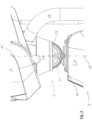
- a first joint element 39 is attached to the upper end of the housing 31 facing the operating handle 7, wherein this first joint element 39 is designed such that an envelope enclosing the first joint element 39 is designed in the shape of a spherical shell. This means that the first joint element 39 itself can be spherical.
- the first joint element 39 is formed, for example, from a plurality of disks arranged parallel to one another, the outer edges of which run in the shape of a circular segment with different diameters, so that the envelope as a whole is in the shape of a spherical shell.
- the first joint element 39 has a projection 41 extending parallel to the vertical axis 17, which is received by an age 43 fastened to the housing 31.
- the first joint element 39 has grooves 45 which are open towards the envelope and which run in the form of a circular segment, which in the embodiment described here are arranged diametrically opposite one another relative to the center of the first joint element 39 and its envelope and run along the envelope. Furthermore, each of the grooves 45 extends over more than 150° in relation to the center of the envelope of the first joint element 39, in the present case even over 180°.
- the joint 9 has a second joint element 47, which is attached to the proximal end 13 of the operating bar and delimits a cavity 49 in which the first joint element 39 is accommodated.
- the cavity 49 is designed in such a way that the first joint element 39 is supported therein in such a way that it can be pivoted about a pivot point 51 that is fixed in relation to the second joint element 47, wherein the pivot point 51 coincides with the center of the envelope of the first joint element 39.
- the support of the first joint element 39 within the second joint element 47 is such that the first joint element 39 and in particular its center cannot be displaced relative to the second joint element 47.
- the first joint element 39 is thus accommodated in the second joint element 47 in a non-displaceable manner.
- the inwardly directed facing surface of the second joint element 47 which delimits the cavity 49, is designed in the shape of a spherical shell. Rather, it is sufficient if sufficiently large support elements 53 are provided inside the second joint element 47, which on the one hand ensure the pivoting movement about the pivot point 51 and on the other hand ensure that the first joint element 39 is held in a non-displaceable manner.
- the second joint element 47 has a circular receiving opening 55, the diameter of which is smaller than the diameter of the envelope of the first joint element 39. This already prevents the first joint element 39 from moving out of the cavity 49.
- engagement parts in the form of rotatably mounted balls 57 are provided on the second joint element 47 on the surface facing inwards towards the cavity 49, which extend into the grooves 45 in the first joint element 39.
- the balls 57 are thus held in a fixed position in the second joint element 47 and can roll in the grooves 45.
- the balls 57 in this embodiment are arranged in a central plane running through the center of the envelope or the pivot point 51 and perpendicular to the longitudinal axis 11 of the operating bar 7.
- they are mounted diametrically opposite relative to the pivot point 51 or center of the envelope.
- the engagement of the engagement parts in the form of the balls 57 with the grooves 45 ensures that even when the longitudinal axis 11 of the operating handle 7 is pivoted relative to the vertical axis 17, a torque is transmitted from the operating handle 7 to the base 5 during a pivoting movement of the operating handle 7 about the longitudinal axis 11, wherein the transmitted torque causes a pivoting movement of the base 5 about the vertical axis 17. Because the balls 57 are rotatably mounted in the second joint element 47 and can roll in the grooves 45, the friction occurring during such a pivoting movement of the operating handle 7 about its longitudinal axis 11 is comparatively low. The base 5 can therefore be easily controlled by a user grasping the actuating end 15.
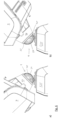
- the joint 9 has a locking arrangement with which the operating handle 7 can be locked in a defined position relative to the base 5 when the locking arrangement is in the locking position.
- the position in which the operating handle 7 can be locked is selected such that the operating handle 7 then extends with its longitudinal axis 11 in such a way that the longitudinal axis 11 runs parallel to an axis that is perpendicular to the cleaning plane 37 or the floor surface 3.
- its longitudinal axis 11 also extends parallel to the vertical axis 17 and is therefore in a vertical position.
- the locking arrangement is in the release position, the operating handle 7 can be pivoted unhindered relative to the base 5.
- the locking arrangement has a locking element 59 which is mounted on the second joint element 47 in such a way that it can be moved along the longitudinal axis 11 of the operating bar 7 and thus perpendicular to the envelope of the first joint element 39 between a release position (see Figure 4 ) and a locking position (see Figure 5 ), whereby this displacement can be effected by an actuating element provided on the actuating field 15 of the operating handle 7 (not shown).
- the actuating element can be coupled to the locking element 59 via an actuating rod or a Bowden cable (not shown).
- the locking element 59 lies opposite a receiving recess 61 in the first joint element 39 when the locking element 59 is in the release position.
- the locking element 59 can extend into the receiving recess 61, which is only possible when the operating handle 7 is in the vertical position already described. If the locking element 59 extends into the receiving recess 61, the operating handle 7 is prevented from pivoting out of the vertical position.
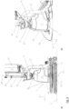
- the arrow 63 indicates a main working direction of the floor cleaning machine 1.
- the main working direction 63 is the direction along which the floor cleaning machine 1 is moved over the floor surface 3 to be cleaned in normal operation, so that this direction 63 indicates the straight-ahead direction during operation.
- a compression spring 65 is arranged on the housing 31 of the base 5, wherein when the operating bar 7 is pivoted against the main working direction 63 relative to the base 5, the compression spring 65 comes into contact with the second joint element 47.
- the compression spring 65 acts as a pre-tensioning element which applies a force to the operating bar 7 in the position shown, pivoted from the vertical position against the main working direction 63, towards the vertical position. In this way, it is achieved that when the operating bar 7, as in Figure 7b ), is pivoted backwards towards the user, the user no longer has to hold the entire weight of the operating handle 7, but is instead supported by the compression spring 65.
- FIG 8 an alternative embodiment of a pre-tensioning element is shown, which reduces the force that a user has to apply in order to hold the operating handle 7 in a position pivoted backwards from the vertical position against the main working direction 63.
- An elastic tension element 67 is provided, which, as Figure 8b ) shows, is stretched when the operating handle 7 is pivoted out of the vertical position against the main working direction 63.
- a force is then exerted on the operating handle 7, by which it is pulled towards the vertical position, which in turn reduces the force that a user must apply to hold the operating handle 7 in the inclined position against the effect of gravity.
- Figure 9 shows a further preferred embodiment of an arrangement with a prestressing element in side view (part a)) and in perspective view (part b)).
- the pretensioning element is designed as a spring element 71 such as a helical spring, which has a first end 69 attached to the operating handle 7 and whose second end 73 is connected to a belt element 75.
- the belt element 75 is guided along the side of the joint 9 pointing in the main working direction 63 from the operating handle 7 to the base 5.
- the belt element 75 is guided adjacent to the joint 9 by a guide element 77, the guide therein being such that the belt element 75 can slide through the guide element 77 and is thus displaceable relative to the guide element 77.
- the belt element 75 is fastened with a fastening end 79 to the base 5 and in this case to its housing 31.
- the belt element 75 is not fastened to the base 5 or its housing 31. It is therefore possible to grasp the belt element 75 in this section between the fastening end 79 and the guide element 77 and to pull it away from the housing 31, whereby the spring element 71 is then stretched. In this way, a gripping loop is then formed, by means of which a user can easily lift in particular the base 5.
- the floor cleaning machine 1 according to the invention with the joint 9 is constructed in such a way that the joint 9 is compact and at the same time enables a transmission of a torque about the longitudinal axis 11 of the operating handle 7 to the base 5.
Landscapes
- Engineering & Computer Science (AREA)
- General Engineering & Computer Science (AREA)
- Mechanical Engineering (AREA)
- Cleaning Implements For Floors, Carpets, Furniture, Walls, And The Like (AREA)
Claims (15)
- Machine de nettoyage du sol (l) comportantune base (5) etune barre de commande (7),dans laquelle la base (5) comporte un agencement d'éléments de nettoyage (27) comportant au moins un élément de nettoyage (33) entraîné, sur lequel est fourni au moins un élément de mise en prise (35),dans laquelle l'élément de nettoyage (33 61) est conçu pour venir en prise, au moyen de l'au moins un élément de mise en prise (35) fourni sur celui-ci, avec une surface de sol (3) à nettoyer,dans laquelle la barre de commande (7) s'étend le long d'un axe longitudinal (11) entre une extrémité proximale (13) et une extrémité d'actionnement (15) et est montée de manière pivotante sur la base (5) par l'intermédiaire d'une articulation (9) de telle sorte que la barre de commande (7) peut pivoter dans n'importe quelle direction par rapport à la base (5),dans laquelle l'articulation (9)comporte un premier élément d'articulation (39) dont l'enveloppe est en forme de cuvette sphérique, etun second élément d'articulation (47),dans laquelle le premier élément d'articulation (39) est logé dans le second élément d'articulation (47) et y est supporté de telle sorteque le premier élément d'articulation (39) peut pivoter par rapport au second élément d'articulation (47) autour d'un point de pivotement (51), lequel est fixe par rapport au second élément d'articulation (47) et lequel coïncide avec le centre de l'enveloppe etque le centre de l'enveloppe est immobile par rapport au second élément d'articulation (47),caractérisée en ce quesur le premier ou le second élément d'articulation (39, 47), sont fournies au moins deux rainures (45) s'étendant en forme de section circulaire, lesquelles sont ouvertes vers l'enveloppe et s'étendent le long de l'enveloppe, et, sur l'autre du premier et du second élément d'articulation (39, 47), sont fournies au moins une première partie de mise en prise (57) et une seconde partie de mise en prise (57), dans laquelle la première partie de mise en prise (57) s'étend dans la première des rainures (45) et la seconde partie de mise en prise (57) s'étend dans la seconde des rainures (45),dans laquelle le premier élément d'articulation (39) est monté sur la base (5) ou l'extrémité proximale (13) de la barre de commande (7) et le second élément d'articulation (47) est appliqué sur l'autre élément parmi la base (5) et l'extrémité proximale (13) de la barre de commande (7).
- Machine de nettoyage du sol selon la revendication 1, dans laquelle les rainures (45) sont agencées diamétralement opposées au premier ou au second éléments d'articulation (39, 47) par rapport au centre de l'enveloppe.
- Machine de nettoyage du sol selon la revendication 1 ou 2, dans laquelle les première et seconde parties de mise en prise (57) sont agencées dans un plan central passant par le centre de l'enveloppe et perpendiculaire à l'axe longitudinal (11) de la barre de commande (7) et diamétralement opposés l'une à l'autre.
- Machine de nettoyage du sol selon l'au moins une des revendications 1 à 3, dans laquelle les rainures (45) s'étendent sur plus de 150 ° autour de l'enveloppe.
- Machine de nettoyage du sol selon l'au moins une des revendications 1 à 4, dans laquelle le second élément d'articulation (47) comporte une ouverture de réception (55) circulaire dont le diamètre est inférieur au diamètre de l'enveloppe.
- Machine de nettoyage du sol selon l'au moins une des revendications 1 à 5, dans laquelle la première et/ou la seconde partie de mise en prise sont réalisées sous la forme de billes (57), lesquelles sont maintenues fixes et rotatives sur l'autre du premier et du second élément d'articulation (39, 47) et peuvent rouler dans l'une des rainures (45).
- Machine de nettoyage du sol selon l'au moins une des revendications 1 à 6, dans laquelle les deux rainures (45) s'étendant en forme de section (45) circulaire sont fournies sur le premier élément d'articulation (39) et la première partie de mise en prise et la seconde partie de mise en prise (57) sont fournies sur le second élément d'articulation (47).
- Machine de nettoyage du sol selon l'au moins une des revendications 1 à 7, dans laquelle le premier élément d'articulation (39) est monté sur la base (5) et le second élément d'articulation (47) est monté sur l'extrémité proximale (13) de la barre de commande (7).
- Machine de nettoyage du sol selon l'au moins une des revendications 1 à 8, dans laquelle l'articulation (9) comporte un agencement de verrouillage, lequel est conçu de telle sorte qu'il puisse être amené dans une position de libération et une position de verrouillage,dans laquelle, dans la position de libération, un mouvement de pivotement du second élément d'articulation (47) autour du premier élément d'articulation (39) est possible etdans laquelle, dans la position de verrouillage, un mouvement de pivotement du second élément d'articulation (47) autour du premier élément d'articulation (39) est impossible.
- Machine de nettoyage du sol selon la revendication 9, dans laquelle le premier ou le second élément d'articulation (39, 47) comporte un évidement de réception (61) dont l'ouverture s'étend vers l'enveloppe,
dans laquelle sur l'autre des premier et second éléments d'articulation (39, 47) est fourni un élément de blocage (59), lequel est déplaçable dans une direction, laquelle s'étend perpendiculairement à l'enveloppe, par rapport à l'autre des premier et second éléments d'articulation (39, 47), de telle sorte que dans la position de libération, il ne s'étend pas au-delà de l'enveloppe vers l'un des premier et second éléments d'articulation (39, 47) et dans la position de verrouillage, il s'étend au-delà de l'enveloppe vers le premier ou le second élément d'articulation (39, 47) dans l'évidement de réception. - Machine de nettoyage du sol selon la revendication 10, dans laquelle l'évidement de réception (61) est fourni sur le premier élément d'articulation (39) et l'élément de blocage (59) est fourni sur le second élément d'articulation (47).
- Machine de nettoyage du sol selon l'au moins une des revendications 1 à 11, dans laquelle l'au moins un élément de mise en prise (35) comporte une extrémité libre,dans laquelle l'au moins une extrémité libre définit un plan de nettoyage dans lequel l'au moins un élément de mise en prise (35) vient en prise avec la surface de sol (3), etdans laquelle la barre de commande (7) peut pivoter par rapport à la base (5) dans une position verticale dans laquelle l'axe longitudinal (11) de la barre de commande (7) s'étend vers le haut en s'éloignant, de préférence perpendiculairement, du plan de nettoyage (37).
- Machine de nettoyage du sol selon l'au moins une des revendications 8 à 11 et selon la revendication 12, dans laquelle, dans la position de verrouillage, la barre de commande (7) est en position verticale.
- Machine de nettoyage du sol selon la revendication 12 ou 13, dans laquelle la machine de nettoyage du sol (1) est conçue pour être déplacée dans une direction de travail principale (63) sur la surface de sol (3) à nettoyer pendant l'opération de nettoyage, et
dans laquelle est fourni un élément de sollicitation (65, 67), lequel est conçu pour exercer une force vers la position verticale sur la barre de commande (7) dans une position pivotée depuis la position verticale contre la direction de travail principale (63). - Machine de nettoyage du sol selon la revendication 14, dans laquelle l'élément de sollicitation est conçu sous la forme d'un élément à ressort (71), fixé à la barre de commande (7) au moyen d'une première extrémité (69), dont la seconde extrémité (73) est reliée à un élément de sangle (75),
dans laquelle l'élément de sangle (75) est guidé depuis la barre de commande (7) jusqu'à la base (5) sur le côté de l'articulation (9) orienté dans la direction de travail principale (63) et est fixé à la base (5).
Applications Claiming Priority (1)
| Application Number | Priority Date | Filing Date | Title |
|---|---|---|---|
| DE102021129923.3A DE102021129923B4 (de) | 2021-11-16 | 2021-11-16 | Handgeführte Bodenreinigungsmaschine |
Publications (3)
| Publication Number | Publication Date |
|---|---|
| EP4179943A1 EP4179943A1 (fr) | 2023-05-17 |
| EP4179943C0 EP4179943C0 (fr) | 2024-07-24 |
| EP4179943B1 true EP4179943B1 (fr) | 2024-07-24 |
Family
ID=84330681
Family Applications (1)
| Application Number | Title | Priority Date | Filing Date |
|---|---|---|---|
| EP22206011.3A Active EP4179943B1 (fr) | 2021-11-16 | 2022-11-08 | Machine de nettoyage de sol guidée à la main |
Country Status (5)
| Country | Link |
|---|---|
| US (1) | US20230148821A1 (fr) |
| EP (1) | EP4179943B1 (fr) |
| KR (1) | KR20230071759A (fr) |
| CN (1) | CN116135125B (fr) |
| DE (1) | DE102021129923B4 (fr) |
Families Citing this family (6)
| Publication number | Priority date | Publication date | Assignee | Title |
|---|---|---|---|---|
| IT202300013308A1 (it) * | 2023-06-27 | 2024-12-27 | Diversey Inc | Dispositivo per la pulizia di pavimenti |
| IT202300013302A1 (it) * | 2023-06-27 | 2024-12-27 | Diversey Inc | Dispositivo per la pulizia di pavimenti |
| IT202300013299A1 (it) * | 2023-06-27 | 2024-12-27 | Diversey Inc | Dispositivo per la pulizia di pavimenti |
| CN117281430B (zh) * | 2023-11-07 | 2025-09-02 | 珠海格力电器股份有限公司 | 清洁刷 |
| CN117257178B (zh) * | 2023-11-07 | 2026-01-30 | 珠海格力电器股份有限公司 | 清洁刷 |
| DE102024105830A1 (de) * | 2024-02-29 | 2025-09-04 | Alfred Kärcher SE & Co. KG | Bodenreinigungsmaschine mit Sperreinrichtung |
Family Cites Families (17)
| Publication number | Priority date | Publication date | Assignee | Title |
|---|---|---|---|---|
| US1090698A (en) | 1911-07-24 | 1914-03-17 | Otto Elbe | Cleaning-tool. |
| US1139736A (en) | 1912-10-16 | 1915-05-18 | Domestic Appliances Company | Cleaning-tool. |
| FR488397A (fr) * | 1917-05-05 | 1918-09-24 | Brown | Dispositif pour le compoundage d'un moteur de laminoir réversible |
| CH149047A (de) * | 1933-05-19 | 1931-08-31 | Jaeck Ernst | Wasch-, Schleif- und Polier-Apparat. |
| DE946260C (de) | 1954-04-14 | 1956-07-26 | Gerhard Unger | Bohnergeraet |
| CN2328331Y (zh) * | 1998-01-22 | 1999-07-14 | 徐载昇 | 一种家用环境清洁器 |
| US6582146B2 (en) * | 2001-02-13 | 2003-06-24 | Trw Inc. | Ball joint seal |
| US7013528B2 (en) * | 2002-01-28 | 2006-03-21 | Bissell Homecare, Inc. | Floor cleaner with dusting |
| AU2010201890B8 (en) * | 2009-05-12 | 2014-07-17 | Bissell Inc. | Upright steam mop sweeper |
| DE102009028944A1 (de) | 2009-08-27 | 2011-03-03 | Rudolf Franke | Handgeführtes Bodenbearbeitungsgerät |
| US8667643B2 (en) * | 2010-09-10 | 2014-03-11 | Euro-Pro Operating Llc | Method and apparatus for assisting pivot motion of a handle in a floor treatment device |
| EP2773254B1 (fr) * | 2011-11-02 | 2019-02-27 | Alfred Kärcher SE & Co. KG | Machine d'entretien du sol poussèe a man |
| WO2015013008A1 (fr) * | 2013-07-22 | 2015-01-29 | The Procter & Gamble Company | Dispositif de nettoyage de sol comportant une plaque formant semelle pouvant recevoir, de manière amovible, une feuille de nettoyage |
| GB2542999B (en) * | 2014-07-25 | 2021-04-28 | Sharkninja Operating Llc | Surface cleaning apparatus with a sideways pivoting handle |
| KR101996272B1 (ko) * | 2017-09-29 | 2019-07-04 | 주식회사 아너스 | 회전식 걸레 청소기 |
| KR102041877B1 (ko) * | 2019-04-26 | 2019-11-06 | 김제훈 | 다기능 밀대 걸레 |
| TWI718691B (zh) * | 2019-10-03 | 2021-02-11 | 燕成祥 | 清潔輪結構 |
-
2021
- 2021-11-16 DE DE102021129923.3A patent/DE102021129923B4/de active Active
-
2022
- 2022-11-08 EP EP22206011.3A patent/EP4179943B1/fr active Active
- 2022-11-14 CN CN202211421815.8A patent/CN116135125B/zh active Active
- 2022-11-15 US US17/987,178 patent/US20230148821A1/en active Pending
- 2022-11-16 KR KR1020220153454A patent/KR20230071759A/ko active Pending
Also Published As
| Publication number | Publication date |
|---|---|
| US20230148821A1 (en) | 2023-05-18 |
| CN116135125A (zh) | 2023-05-19 |
| CN116135125B (zh) | 2025-04-04 |
| DE102021129923B4 (de) | 2024-07-04 |
| DE102021129923A1 (de) | 2023-05-17 |
| KR20230071759A (ko) | 2023-05-23 |
| EP4179943C0 (fr) | 2024-07-24 |
| EP4179943A1 (fr) | 2023-05-17 |
Similar Documents
| Publication | Publication Date | Title |
|---|---|---|
| EP4179943B1 (fr) | Machine de nettoyage de sol guidée à la main | |
| DE69829920T2 (de) | Vorschubsteuereinheit für Rohrreinigungswerkzeuge | |
| DE102021116685B3 (de) | Bodenreinigungsmaschine | |
| DE10329771B4 (de) | Antriebsvorrichtung für einen Reinigungsroboter | |
| DE3525374A1 (de) | Hoeheneinstelleinrichtung fuer einen fahrzeugsitz | |
| DE3903041C5 (de) | Handbiegegerät für Rohre, Stangen und dgl. | |
| DE1507254B1 (de) | Zusammenlegbare Lenkstange fuer Rasenmaeher | |
| EP0098482B1 (fr) | Dispositif de levage ou de dépose pour des réceptacles transportables, par exemple conteneurs, abris, structures amovibles ou semblables | |
| DE2619031C2 (fr) | ||
| DE202007004390U1 (de) | Auswringbarer Mopp | |
| DE102021116683B4 (de) | Bodenreinigungsmaschine | |
| DE19916626C1 (de) | Wischmop mit Stiel | |
| DE2949271A1 (de) | Greifzange zum handhaben oder anheben von blechen o.dgl. | |
| EP1176892B1 (fr) | Dispositif d'ajustement pour faire pivoter l'element pivotant d'un meuble relevant de l'ameublement domestique, de l'ameublement de bureau ou de celui du domaine des soins, par rapport a un element fixe dudit meuble | |
| EP0180831A1 (fr) | Pince à tuyaux | |
| EP3503788B1 (fr) | Balai | |
| EP0993265A1 (fr) | Appareil nettoyeur | |
| DE4131858C2 (fr) | ||
| DE102024103773B4 (de) | Koppelmechanismus | |
| DE19838080C2 (de) | Vorrichtung zur Bodenbearbeitung | |
| DE1507254C (fr) | ||
| DE2620874C3 (de) | Vorrichtung zum Antrieb eines Transportbodens | |
| DE3515657A1 (de) | Abziehvorrichtung fuer lkw-raeder | |
| DE202026100243U1 (de) | Teleskopischer Greifer | |
| DE8510957U1 (de) | Höhenverstellbare Anhängevorrichtung |
Legal Events
| Date | Code | Title | Description |
|---|---|---|---|
| PUAI | Public reference made under article 153(3) epc to a published international application that has entered the european phase |
Free format text: ORIGINAL CODE: 0009012 |
|
| STAA | Information on the status of an ep patent application or granted ep patent |
Free format text: STATUS: THE APPLICATION HAS BEEN PUBLISHED |
|
| AK | Designated contracting states |
Kind code of ref document: A1 Designated state(s): AL AT BE BG CH CY CZ DE DK EE ES FI FR GB GR HR HU IE IS IT LI LT LU LV MC ME MK MT NL NO PL PT RO RS SE SI SK SM TR |
|
| STAA | Information on the status of an ep patent application or granted ep patent |
Free format text: STATUS: REQUEST FOR EXAMINATION WAS MADE |
|
| 17P | Request for examination filed |
Effective date: 20231115 |
|
| RBV | Designated contracting states (corrected) |
Designated state(s): AL AT BE BG CH CY CZ DE DK EE ES FI FR GB GR HR HU IE IS IT LI LT LU LV MC ME MK MT NL NO PL PT RO RS SE SI SK SM TR |
|
| REG | Reference to a national code |
Ref country code: HK Ref legal event code: DE Ref document number: 40094950 Country of ref document: HK |
|
| GRAP | Despatch of communication of intention to grant a patent |
Free format text: ORIGINAL CODE: EPIDOSNIGR1 |
|
| STAA | Information on the status of an ep patent application or granted ep patent |
Free format text: STATUS: GRANT OF PATENT IS INTENDED |
|
| RIC1 | Information provided on ipc code assigned before grant |
Ipc: A47L 13/00 20060101ALI20240122BHEP Ipc: A47L 11/40 20060101ALI20240122BHEP Ipc: A47L 11/00 20060101AFI20240122BHEP |
|
| INTG | Intention to grant announced |
Effective date: 20240214 |
|
| GRAS | Grant fee paid |
Free format text: ORIGINAL CODE: EPIDOSNIGR3 |
|
| GRAA | (expected) grant |
Free format text: ORIGINAL CODE: 0009210 |
|
| STAA | Information on the status of an ep patent application or granted ep patent |
Free format text: STATUS: THE PATENT HAS BEEN GRANTED |
|
| AK | Designated contracting states |
Kind code of ref document: B1 Designated state(s): AL AT BE BG CH CY CZ DE DK EE ES FI FR GB GR HR HU IE IS IT LI LT LU LV MC ME MK MT NL NO PL PT RO RS SE SI SK SM TR |
|
| REG | Reference to a national code |
Ref country code: GB Ref legal event code: FG4D Free format text: NOT ENGLISH |
|
| REG | Reference to a national code |
Ref country code: CH Ref legal event code: EP |
|
| REG | Reference to a national code |
Ref country code: DE Ref legal event code: R096 Ref document number: 502022001301 Country of ref document: DE |
|
| REG | Reference to a national code |
Ref country code: IE Ref legal event code: FG4D Free format text: LANGUAGE OF EP DOCUMENT: GERMAN |
|
| U01 | Request for unitary effect filed |
Effective date: 20240823 |
|
| U07 | Unitary effect registered |
Designated state(s): AT BE BG DE DK EE FI FR IT LT LU LV MT NL PT RO SE SI Effective date: 20240902 |
|
| U20 | Renewal fee for the european patent with unitary effect paid |
Year of fee payment: 3 Effective date: 20241125 |
|
| PG25 | Lapsed in a contracting state [announced via postgrant information from national office to epo] |
Ref country code: NO Free format text: LAPSE BECAUSE OF FAILURE TO SUBMIT A TRANSLATION OF THE DESCRIPTION OR TO PAY THE FEE WITHIN THE PRESCRIBED TIME-LIMIT Effective date: 20241024 |
|
| PG25 | Lapsed in a contracting state [announced via postgrant information from national office to epo] |
Ref country code: GR Free format text: LAPSE BECAUSE OF FAILURE TO SUBMIT A TRANSLATION OF THE DESCRIPTION OR TO PAY THE FEE WITHIN THE PRESCRIBED TIME-LIMIT Effective date: 20241025 Ref country code: PL Free format text: LAPSE BECAUSE OF FAILURE TO SUBMIT A TRANSLATION OF THE DESCRIPTION OR TO PAY THE FEE WITHIN THE PRESCRIBED TIME-LIMIT Effective date: 20240724 |
|
| PG25 | Lapsed in a contracting state [announced via postgrant information from national office to epo] |
Ref country code: IS Free format text: LAPSE BECAUSE OF FAILURE TO SUBMIT A TRANSLATION OF THE DESCRIPTION OR TO PAY THE FEE WITHIN THE PRESCRIBED TIME-LIMIT Effective date: 20241124 |
|
| PG25 | Lapsed in a contracting state [announced via postgrant information from national office to epo] |
Ref country code: HR Free format text: LAPSE BECAUSE OF FAILURE TO SUBMIT A TRANSLATION OF THE DESCRIPTION OR TO PAY THE FEE WITHIN THE PRESCRIBED TIME-LIMIT Effective date: 20240724 |
|
| PG25 | Lapsed in a contracting state [announced via postgrant information from national office to epo] |
Ref country code: RS Free format text: LAPSE BECAUSE OF FAILURE TO SUBMIT A TRANSLATION OF THE DESCRIPTION OR TO PAY THE FEE WITHIN THE PRESCRIBED TIME-LIMIT Effective date: 20241024 Ref country code: ES Free format text: LAPSE BECAUSE OF FAILURE TO SUBMIT A TRANSLATION OF THE DESCRIPTION OR TO PAY THE FEE WITHIN THE PRESCRIBED TIME-LIMIT Effective date: 20240724 |
|
| PG25 | Lapsed in a contracting state [announced via postgrant information from national office to epo] |
Ref country code: RS Free format text: LAPSE BECAUSE OF FAILURE TO SUBMIT A TRANSLATION OF THE DESCRIPTION OR TO PAY THE FEE WITHIN THE PRESCRIBED TIME-LIMIT Effective date: 20241024 Ref country code: PL Free format text: LAPSE BECAUSE OF FAILURE TO SUBMIT A TRANSLATION OF THE DESCRIPTION OR TO PAY THE FEE WITHIN THE PRESCRIBED TIME-LIMIT Effective date: 20240724 Ref country code: NO Free format text: LAPSE BECAUSE OF FAILURE TO SUBMIT A TRANSLATION OF THE DESCRIPTION OR TO PAY THE FEE WITHIN THE PRESCRIBED TIME-LIMIT Effective date: 20241024 Ref country code: IS Free format text: LAPSE BECAUSE OF FAILURE TO SUBMIT A TRANSLATION OF THE DESCRIPTION OR TO PAY THE FEE WITHIN THE PRESCRIBED TIME-LIMIT Effective date: 20241124 Ref country code: HR Free format text: LAPSE BECAUSE OF FAILURE TO SUBMIT A TRANSLATION OF THE DESCRIPTION OR TO PAY THE FEE WITHIN THE PRESCRIBED TIME-LIMIT Effective date: 20240724 Ref country code: GR Free format text: LAPSE BECAUSE OF FAILURE TO SUBMIT A TRANSLATION OF THE DESCRIPTION OR TO PAY THE FEE WITHIN THE PRESCRIBED TIME-LIMIT Effective date: 20241025 Ref country code: ES Free format text: LAPSE BECAUSE OF FAILURE TO SUBMIT A TRANSLATION OF THE DESCRIPTION OR TO PAY THE FEE WITHIN THE PRESCRIBED TIME-LIMIT Effective date: 20240724 |
|
| PG25 | Lapsed in a contracting state [announced via postgrant information from national office to epo] |
Ref country code: SM Free format text: LAPSE BECAUSE OF FAILURE TO SUBMIT A TRANSLATION OF THE DESCRIPTION OR TO PAY THE FEE WITHIN THE PRESCRIBED TIME-LIMIT Effective date: 20240724 |
|
| PG25 | Lapsed in a contracting state [announced via postgrant information from national office to epo] |
Ref country code: CZ Free format text: LAPSE BECAUSE OF FAILURE TO SUBMIT A TRANSLATION OF THE DESCRIPTION OR TO PAY THE FEE WITHIN THE PRESCRIBED TIME-LIMIT Effective date: 20240724 |
|
| PG25 | Lapsed in a contracting state [announced via postgrant information from national office to epo] |
Ref country code: SK Free format text: LAPSE BECAUSE OF FAILURE TO SUBMIT A TRANSLATION OF THE DESCRIPTION OR TO PAY THE FEE WITHIN THE PRESCRIBED TIME-LIMIT Effective date: 20240724 |
|
| PLBE | No opposition filed within time limit |
Free format text: ORIGINAL CODE: 0009261 |
|
| STAA | Information on the status of an ep patent application or granted ep patent |
Free format text: STATUS: NO OPPOSITION FILED WITHIN TIME LIMIT |
|
| 26N | No opposition filed |
Effective date: 20250425 |
|
| PG25 | Lapsed in a contracting state [announced via postgrant information from national office to epo] |
Ref country code: MC Free format text: LAPSE BECAUSE OF FAILURE TO SUBMIT A TRANSLATION OF THE DESCRIPTION OR TO PAY THE FEE WITHIN THE PRESCRIBED TIME-LIMIT Effective date: 20240724 |
|
| PG25 | Lapsed in a contracting state [announced via postgrant information from national office to epo] |
Ref country code: IE Free format text: LAPSE BECAUSE OF NON-PAYMENT OF DUE FEES Effective date: 20241108 |
|
| REG | Reference to a national code |
Ref country code: CH Ref legal event code: U11 Free format text: ST27 STATUS EVENT CODE: U-0-0-U10-U11 (AS PROVIDED BY THE NATIONAL OFFICE) Effective date: 20251201 |
|
| U20 | Renewal fee for the european patent with unitary effect paid |
Year of fee payment: 4 Effective date: 20251117 |
|
| PGFP | Annual fee paid to national office [announced via postgrant information from national office to epo] |
Ref country code: CH Payment date: 20251201 Year of fee payment: 4 |
|
| PG25 | Lapsed in a contracting state [announced via postgrant information from national office to epo] |
Ref country code: HU Free format text: LAPSE BECAUSE OF FAILURE TO SUBMIT A TRANSLATION OF THE DESCRIPTION OR TO PAY THE FEE WITHIN THE PRESCRIBED TIME-LIMIT; INVALID AB INITIO Effective date: 20221108 |
|
| PG25 | Lapsed in a contracting state [announced via postgrant information from national office to epo] |
Ref country code: CY Free format text: LAPSE BECAUSE OF FAILURE TO SUBMIT A TRANSLATION OF THE DESCRIPTION OR TO PAY THE FEE WITHIN THE PRESCRIBED TIME-LIMIT; INVALID AB INITIO Effective date: 20221108 |