EP4179946A1 - Procédé de fonctionnement d'un appareil ménager à circulation d'eau - Google Patents
Procédé de fonctionnement d'un appareil ménager à circulation d'eau Download PDFInfo
- Publication number
- EP4179946A1 EP4179946A1 EP22210043.0A EP22210043A EP4179946A1 EP 4179946 A1 EP4179946 A1 EP 4179946A1 EP 22210043 A EP22210043 A EP 22210043A EP 4179946 A1 EP4179946 A1 EP 4179946A1
- Authority
- EP
- European Patent Office
- Prior art keywords
- water
- filter element
- rinsing process
- annular flow
- washing
- Prior art date
- Legal status (The legal status is an assumption and is not a legal conclusion. Google has not performed a legal analysis and makes no representation as to the accuracy of the status listed.)
- Granted
Links
Images


Classifications
-
- A—HUMAN NECESSITIES
- A47—FURNITURE; DOMESTIC ARTICLES OR APPLIANCES; COFFEE MILLS; SPICE MILLS; SUCTION CLEANERS IN GENERAL
- A47L—DOMESTIC WASHING OR CLEANING; SUCTION CLEANERS IN GENERAL
- A47L15/00—Washing or rinsing machines for crockery or tableware
- A47L15/0018—Controlling processes, i.e. processes to control the operation of the machine characterised by the purpose or target of the control
- A47L15/0021—Regulation of operational steps within the washing processes, e.g. optimisation or improvement of operational steps depending from the detergent nature or from the condition of the crockery
- A47L15/0039—Filter cleaning phases
-
- A—HUMAN NECESSITIES
- A47—FURNITURE; DOMESTIC ARTICLES OR APPLIANCES; COFFEE MILLS; SPICE MILLS; SUCTION CLEANERS IN GENERAL
- A47L—DOMESTIC WASHING OR CLEANING; SUCTION CLEANERS IN GENERAL
- A47L15/00—Washing or rinsing machines for crockery or tableware
- A47L15/42—Details
- A47L15/4202—Water filter means or strainers
- A47L15/4208—Arrangements to prevent clogging of the filters, e.g. self-cleaning
-
- A—HUMAN NECESSITIES
- A47—FURNITURE; DOMESTIC ARTICLES OR APPLIANCES; COFFEE MILLS; SPICE MILLS; SUCTION CLEANERS IN GENERAL
- A47L—DOMESTIC WASHING OR CLEANING; SUCTION CLEANERS IN GENERAL
- A47L15/00—Washing or rinsing machines for crockery or tableware
- A47L15/42—Details
- A47L15/4214—Water supply, recirculation or discharge arrangements; Devices therefor
- A47L15/4219—Water recirculation
- A47L15/4221—Arrangements for redirection of washing water, e.g. water diverters to selectively supply the spray arms
-
- B—PERFORMING OPERATIONS; TRANSPORTING
- B01—PHYSICAL OR CHEMICAL PROCESSES OR APPARATUS IN GENERAL
- B01D—SEPARATION
- B01D29/00—Filters with filtering elements stationary during filtration, e.g. pressure or suction filters, not covered by groups B01D24/00 - B01D27/00; Filtering elements therefor
- B01D29/11—Filters with filtering elements stationary during filtration, e.g. pressure or suction filters, not covered by groups B01D24/00 - B01D27/00; Filtering elements therefor with bag, cage, hose, tube, sleeve or like filtering elements
- B01D29/114—Filters with filtering elements stationary during filtration, e.g. pressure or suction filters, not covered by groups B01D24/00 - B01D27/00; Filtering elements therefor with bag, cage, hose, tube, sleeve or like filtering elements arranged for inward flow filtration
-
- B—PERFORMING OPERATIONS; TRANSPORTING
- B01—PHYSICAL OR CHEMICAL PROCESSES OR APPARATUS IN GENERAL
- B01D—SEPARATION
- B01D29/00—Filters with filtering elements stationary during filtration, e.g. pressure or suction filters, not covered by groups B01D24/00 - B01D27/00; Filtering elements therefor
- B01D29/62—Regenerating the filter material in the filter
- B01D29/64—Regenerating the filter material in the filter by scrapers, brushes, nozzles, or the like, acting on the cake side of the filtering element
- B01D29/6438—Regenerating the filter material in the filter by scrapers, brushes, nozzles, or the like, acting on the cake side of the filtering element nozzles
-
- C—CHEMISTRY; METALLURGY
- C02—TREATMENT OF WATER, WASTE WATER, SEWAGE, OR SLUDGE
- C02F—TREATMENT OF WATER, WASTE WATER, SEWAGE, OR SLUDGE
- C02F1/00—Treatment of water, waste water, or sewage
- C02F1/001—Processes for the treatment of water whereby the filtration technique is of importance
-
- C—CHEMISTRY; METALLURGY
- C02—TREATMENT OF WATER, WASTE WATER, SEWAGE, OR SLUDGE
- C02F—TREATMENT OF WATER, WASTE WATER, SEWAGE, OR SLUDGE
- C02F2103/00—Nature of the water, waste water, sewage or sludge to be treated
- C02F2103/002—Grey water, e.g. from clothes washers, showers or dishwashers
-
- C—CHEMISTRY; METALLURGY
- C02—TREATMENT OF WATER, WASTE WATER, SEWAGE, OR SLUDGE
- C02F—TREATMENT OF WATER, WASTE WATER, SEWAGE, OR SLUDGE
- C02F2303/00—Specific treatment goals
- C02F2303/16—Regeneration of sorbents, filters
-
- C—CHEMISTRY; METALLURGY
- C02—TREATMENT OF WATER, WASTE WATER, SEWAGE, OR SLUDGE
- C02F—TREATMENT OF WATER, WASTE WATER, SEWAGE, OR SLUDGE
- C02F2307/00—Location of water treatment or water treatment device
- C02F2307/12—Location of water treatment or water treatment device as part of household appliances such as dishwashers, laundry washing machines or vacuum cleaners
Definitions
- the present invention relates to a water-bearing household appliance and a method for operating a water-bearing household appliance.
- a dishwasher has a washing compartment, on the bottom of which a pump sump can be provided.
- a filter sieve for filtering washing liquor is usually arranged in the pump well. To clean the filter screen, it can be removed and cleaned manually.
- the U.S. 7,431,774 B2 a dishwasher with a sump and a filter arranged in the sump.
- Cleaning nozzles are provided in the sump and have a large number of fluid outlet openings for spraying on the filter.
- an object of the present invention is to provide an improved water-conducting household appliance.
- a water-conducting domestic appliance in particular a domestic dishwasher, is provided with a pump sump, a filter element arranged at least in sections in the pump sump, and a nozzle device that is arranged on the pump sump, the nozzle device being set up to emit a flow in only one direction around the To generate filter element flowing annular flow between the sump and the filter element for detaching dirt from the filter element.
- annular flow means a fluid mass flow, in particular a washing liquor mass flow.
- washing liquor means a fluid such as water, for example, which can contain cleaning additives and dirt, for example.
- the nozzle device is preferably a component which is separate from the pump sump and comprises, for example, plastic or metal or is formed from plastic or metal. Alternatively, the nozzle device can be integrally formed onto the pump sump.
- the nozzle device preferably comprises a channel for channeling a fluid or washing liquor.
- the filter element comprises a microfilter which is tubular, a microfilter inside surrounding an interior of the microfilter and a microfilter outside, the nozzle device being set up to generate the annular flow around the microfilter outside, so that the dirt from the microfilter inside to the interior to be replaced.
- the filter element can include a coarse filter, which is arranged above the microfilter and is connected to it, for example.
- the filter element can include a fine filter, which is arranged, for example, above the microfilter and optionally around the coarse filter.
- the fine filter can be designed, for example, as a flat and fine screen structure.
- the coarse filter can, for example, have the shape of a pot and be designed as a coarse sieve structure.
- the microfilter can also be designed as a sieve structure.
- tubular sieve structure that differs from the sieve structure
- the microfilter can thus be formed from different screen structures, for example.
- the inside of the microfilter and/or the outside of the microfilter can, for example, essentially have the shape of a cylinder jacket.
- the inside of the microfilter and/or the outside of the microfilter can have, for example, an endless bellows-shaped design.
- tubular means that the microfilter has a ring-shaped cross section, in particular a circular ring-shaped design.
- the nozzle device preferably comprises only fluid outlet openings or one fluid outlet opening, each set up for this purpose are to form or ensure a fluid outlet running essentially tangentially to a tube shape of the microfilter.
- the water-carrying household appliance includes a drain pump which is set up to suck the washing solution and dirt directly out of the interior.
- the pump well comprises, for example, an opening which faces the interior of the microfilter and through which the drain pump draws in washing liquor from the interior of the microfilter.
- the drain pump is set up, for example, to suck off or convey washing liquor together with the dirt to a drain outside the household appliance.
- the pump sump has a side wall which surrounds the filter element, so that an annular gap is formed between the filter element and the side wall.
- the side wall is a wall of the filter mount of the pump sump.
- a bottom wall for example, can be formed onto the side wall, which together form the filter holder.
- the side wall and the filter element are arranged in such a way that the annular flow is shaped or formed.
- the annular flow runs along the wall.
- the side wall surrounds the filter element radially, for example, and extends in a depth direction, which points vertically downwards, for example.
- the side wall has a radial opening through which washing liquor filtered by the filter element and flowing from the interior of the microfilter to the annular gap can be conveyed.
- the annular gap can be seen as an annular space between the microfilter and the filter mount.
- the nozzle device comprises a first nozzle section which protrudes into the annular gap from above.
- the first nozzle section has one or more fluid outlet openings, each of which is set up to shape or ensure the fluid outlet running essentially tangentially to the tube shape of the microfilter.
- the nozzle device comprises a second nozzle section, onto which the first nozzle section is formed and which extends away from the annular gap.
- the second nozzle section extends, for example, radially or tangentially away from the tube shape of the microfilter. This has the advantage that flow losses can be reduced since a channel of the second nozzle section has fewer or no bends.
- the first nozzle section is curved around the filter element.
- the first nozzle section fits ideally into the annular gap, since the first nozzle section follows the course of the annular gap in a section of the annular gap, for example.
- the first nozzle section is in the form of a segment of a circular ring.
- the water-carrying domestic appliance comprises a water diverter which is set up to interrupt a fluid supply to the nozzle device, so that the annular flow is interrupted.
- the water-bearing household appliance comprises a spray arm and/or two spray arms and/or a ceiling spray device, the water diverter being set up to interrupt and/or close a fluid supply to the spray arm and/or the two spray arms and/or the ceiling spray device steer.
- the sump includes a circulating pump which is set up to circulate washing liquor and to supply the first spray arm and/or the second spray arm and/or the ceiling spray device with washing liquor. It goes without saying that corresponding channels are formed.
- a method for operating a water-bearing household appliance in particular as described above, is provided, with the aid of a nozzle device generating an annular flow flowing around a filter element in only one direction of flow between a pump well and the filter element for removing dirt from the filter element.
- the annular flow is generated for between 20 and 240 seconds, preferably between 40 and 220 seconds and more preferably between 60 and 180 seconds.
- a first rinsing process is carried out, in which the washing liquor circulates within the water-bearing household appliance, with the washing liquor and dirt being sucked off using a drain pump after the first rinsing process, and the annular flow during, in particular at the end of, the first rinsing process is generated.
- the annular flow is interrupted before the washing liquor is first drawn off.
- suction can also be referred to as pumping out.
- a second rinsing process in which the rinsing water circulates within the water-bearing household appliance, is carried out, wherein after the second rinsing process a second suction of rinsing water and dirt is carried out with the aid of the drain pump, and the annular flow during, in particular at the end of the second rinsing process.
- the ring flow is interrupted before the second suction of washing liquor.
- the annular flow is generated while the washing liquor and dirt are being suctioned off with the aid of a drain pump.
- the annular flow is switched on by switching over a water diverter.
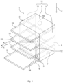
- the 1 shows a schematic perspective view of a water-bearing domestic appliance 1, in particular a domestic dishwasher.
- the household appliance 1 includes a washing compartment 2, which can be closed by a door 3, which is in particular watertight.
- a sealing device can be provided between the door 3 and the washing container 2 .
- the washing compartment 2 is preferably cuboid.
- the washing container 2 can be arranged in a housing of the household appliance 1 .
- the washing compartment 2 and the door 3 can form a washing chamber 4 for washing items to be washed.
- Door 3 is in the 1 shown in their open position.
- the door 3 can be closed or opened by pivoting about a pivot axis 5 provided at a lower end of the door 3 .
- a loading opening 6 of the washing compartment 2 can be closed or opened.
- the washing compartment 2 has a base plate 7, a cover 8 arranged opposite the base plate 7, a rear wall 9 arranged opposite the closed door 3 and two side walls 10, 11 arranged opposite one another.
- the floor panel 7, the ceiling 8, the rear wall 9 and the side walls 10, 11 can be made of sheet steel, for example.
- the floor panel 7 can be made of a different material than the cover 8 and the side walls 10, 11.
- the floor panel 7 can be made of the material 1.4301, the cover 8 and the side walls 10, 11 can be made of the material 1.4016 and the rear wall 9 also be made of the material 1.4016.
- the floor panel 7 can also be made of a plastic material.
- the household appliance 1 also has a floor arrangement 12 provided on the floor panel 7 .
- the domestic appliance 1 also has at least one washware holder 13 to 15 .
- washware holders 13 to 15 can be provided, with the washware holder 13 being a lower washware holder or a lower rack, the washware holder 14 being an upper washware holder or an upper rack and the washware holder 15 being a cutlery drawer.
- the washing items receptacles 13 to 15 are arranged one above the other in the washing compartment 2 .
- Each wash item holder 13 to 15 can be moved either into or out of the washing container 2 .
- each washware receptacle 13 to 15 can be pushed into the washing compartment 2 in an insertion direction E and pulled out of the washing compartment 2 in a pull-out direction A counter to the insertion direction E.
- a ceiling spray device 16 is provided on the ceiling 6 , which is set up to spray washing liquor in the washing compartment 4 .
- a spray arm 38 (here also referred to as the first spray arm) is provided between the base plate 7 and the washware receptacle 13 .
- the spray arm 38 is rotatably connected to the floor panel 7 and/or the floor arrangement 12 and is set up to spray washing liquor in the washing compartment 4 .
- a spray arm 39 (here also referred to as a second spray arm) is provided, which is rotatably connected to an underside of the wash items receptacle 14 and which is set up to spray wash liquor in the wash cabinet 4 .
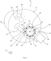
- the base arrangement 12 comprises a pump well 17, a filter element 18 which is arranged at least in sections in the pump well 17 and a nozzle device 19 which is arranged at least in sections between the pump well 17 and the filter element 18, the nozzle device 19 being set up to produce a flow in only one direction R to generate an annular flow 20 flowing around the filter element 18 between a side wall 21 of the sump 17 and the filter element 18 for detaching dirt from the filter element 18 .
- the pump sump 17 can be formed in one piece, in particular in one piece of material, with the washing container 2 , in particular with the base plate 7 .
- the side wall 21 extends in a depth direction z, which extends from the ceiling 8 (see 1 ) vertically downwards to the floor panel 7 (see 1 ) shows. Furthermore, the flow direction R runs perpendicularly to the depth direction z and, for example, counterclockwise when viewed from above. Alternatively, the direction of flow R can run clockwise when viewed from above.
- a base wall 22 is formed on the side wall 21 and preferably runs essentially perpendicularly to the side wall 21 and on which the filter element 18 stands. The side wall 21 and the bottom wall 22 form a filter receptacle of the pump sump 17 .
- the filter element 18 comprises a microfilter 23 which is tubular in design and has a microfilter inner side 25 which encloses an interior space 24 of the microfilter 23 and a microfilter outside 26, wherein the nozzle device 19 is set up to generate the annular flow 20 around the microfilter outside 26, so that the dirt is detached from the microfilter inside 25 to the interior 24.
- the floor arrangement 12 also includes a drain pump 27 which is set up to suck the washing solution and dirt directly out of the interior 24 .
- an opening 28 of the pump sump 17 arranged below the interior 24 is provided, which faces the inner space 24 and is fluidly connected to the drain pump 27 with the aid of a fluid channel (not shown) arranged below the opening 28 .
- the side wall 21 surrounds the filter element 18 in such a way that an annular gap 29 is formed between the filter element 18 and the side wall 21 .
- the side wall 21 has an angular shape, with the side wall 21 having rounded and flattened wall sections.
- the side wall 21 could have no corners when viewed from above and could have a circular or oval contour, for example.
- the nozzle device 19 comprises a first nozzle section 30 which protrudes into the annular gap 29 from above and has a fluid outlet opening 32 from which a fluid jet leaves the nozzle device 19 to form the annular flow 20 .
- the nozzle device 19 comprises a second nozzle section 31 on which the first nozzle section 30 is formed, the second nozzle section 31 extending away from the annular gap 29 .
- only fluid outlet openings 32 are provided on the nozzle device 19 , which are each set up to shape or ensure a fluid outlet running essentially tangentially to the annular shape of the microfilter 23 . In other words, for example, no fluid outlet opening is provided on the nozzle device 19 that forms a fluid outlet directly towards the interior space 24 .
- the bottom arrangement 12 comprises a water diverter 33 which is set up to interrupt a fluid supply to the nozzle device 19 so that the annular flow 20 is interrupted. Furthermore, the water diverter 33 is set up to supply fluid to the spray arm 38 (see 1 ) and/or the spray arm 39 (see 1 ) and/or the ceiling spray device 16 (see 1 ) to interrupt and/or control.
- the sump 17 further includes a first opening 34, by means of which the Ceiling spray device 16 is supplied with washing liquid and/or a second opening 35, by means of which the spray arm 39 is supplied with washing liquid and/or a third opening 36, by means of which the spray arm 38 is supplied with washing liquid.
- FIG 3 shows a second embodiment of the base arrangement 12 of the household appliance 1 viewed from a schematic top view.
- the first nozzle section 30 is curved around the filter element 18 .
- a wall 37 of the first nozzle section 30 faces the filter element 18 and is adapted to the tube shape of the microfilter 23 . This has the advantage that the first nozzle section 30 fits ideally into the annular gap 29 since the first nozzle section 30 follows the course of the annular gap 29 at least in sections.
- the first nozzle section 30 extends out of the annular gap 29 counter to the depth direction z and merges into the second nozzle section 31 , which extends towards the water diverter 33 .
- the second nozzle section 31 extends essentially perpendicular to the depth direction z.
- FIG 4 shows a schematic diagram of an exemplary rinsing process 40 for the water-bearing household appliance 1 according to FIG 1 .
- the rinsing process 40 begins at a point in time t0. Between the point in time t0 and a point in time t1, the quantity M of rinsing liquor is increased by supplying fresh water. A pre-rinsing process 41 is started between times t1 and t2. The drain pump 27 is activated between the point in time t2 and a point in time t3, thereby reducing the quantity M of washing liquor. Subsequently, the amount of washing liquor M is increased up to a point in time t4 and a rinsing process 42 (here also referred to as the first rinsing process) is started, which is carried out up to the point in time t6.
- a rinsing process 42 here also referred to as the first rinsing process
- rinsing liquor circulates within the water-bearing domestic appliance 1.
- the circulating (or circulating) is carried out with the aid of the circulating pump.
- the drain pump 27 is activated and the washing liquor is essentially completely, for example or partially pumped out. This can be referred to as suction 45 (here also referred to as first suction).
- the annular flow 20 is preferably generated during, in particular at the end of, the flushing process 42 between a point in time t5 and point in time t6 and/or point in time t7.
- the rinsing process 43 in which the rinsing water circulates within the water-bearing household appliance 1, is carried out, with the rinsing process 43 being followed by the suction 46 of rinsing water and dirt with the aid of the drain pump 27, and the annular flow 20 during, in particular on End of the second rinsing process 43 is generated between a point in time t9 and the point in time t10 and/or t11.
- the ring flow 20 is generated during, in particular at the end, of the rinsing process 44 between a point in time t13 and a point in time t14 and/or t15.
- the washing liquor pumped out during suction 47 has a higher temperature than the washing liquor pumped out during suction 45 or suction 46 .
- the temperature of the washing liquor can be 55°C to 65°C, in particular 58°C or 63°C, before or during suction. Because of the higher temperature, an increased cleaning effect on the filter element 18 can be achieved become.
- the annular flow 20 may be activated between time t13 and time t14 or time t15 longer than the annular flow 20 between time t5 and time t6 or time t7 and/or than the annular flow 20 between time t9 and time t9 t10 or time t11.
- the annular flow 20 can be generated, for example, for between 20 and 240 seconds, preferably between 40 and 220 seconds and more preferably between 60 and 180 seconds.
- the annular flow 20 is generated for 90 seconds between times t5 and t6 or t7.
- the annular flow 20 is generated between times t9 and t10 or t11 for 90 seconds.
- the annular flow 20 is generated between times t13 and t14 or t15 for 180 seconds.
- the annular flow 20 is generated with the aid of the drain pump 27 during a suction 45 , 46 , 47 of washing liquor together with the dirt.
- the annular flow 20 can, for example, also be activated exactly once, twice, three times, four times or five times during the flushing process 40, e.g. during the pre-rinse process 41 and/or during the rinse process 42 and/or during the rinse process 43 and/or during the final-rinse process 44 and/or during the suction 45 and/or during the suction 46 and/or during the suction 47.
- the annular flow 20 is switched on in each case with the aid of switching over the water diverter 33 .
- the amount of washing liquid M remains essentially constant.
- the rinsing process 42 can be referred to as the cleaning phase and the rinsing process 43 as the intermediate rinsing phase.
- the drain pump 27 and the nozzle device 19 can be activated simultaneously in order to bring about an increased detachment effect on the dirt.
Landscapes
- Chemical & Material Sciences (AREA)
- Engineering & Computer Science (AREA)
- Water Supply & Treatment (AREA)
- Chemical Kinetics & Catalysis (AREA)
- Life Sciences & Earth Sciences (AREA)
- Hydrology & Water Resources (AREA)
- Environmental & Geological Engineering (AREA)
- Organic Chemistry (AREA)
- Washing And Drying Of Tableware (AREA)
- Cleaning By Liquid Or Steam (AREA)
- Structures Of Non-Positive Displacement Pumps (AREA)
- Apparatus For Making Beverages (AREA)
Applications Claiming Priority (3)
| Application Number | Priority Date | Filing Date | Title |
|---|---|---|---|
| DE102017217801.9A DE102017217801A1 (de) | 2017-10-06 | 2017-10-06 | Wasserführendes Haushaltsgerät und Verfahren zum Betreiben eines wasserführenden Haushaltsgeräts |
| EP18779347.6A EP3691507B1 (fr) | 2017-10-06 | 2018-09-26 | Appareil ménager à circulation d'eau et procédé permettant de faire fonctionner un appareil ménager à circulation d'eau |
| PCT/EP2018/076070 WO2019068528A1 (fr) | 2017-10-06 | 2018-09-26 | Appareil ménager à circulation d'eau et procédé permettant de faire fonctionner un appareil ménager à circulation d'eau |
Related Parent Applications (2)
| Application Number | Title | Priority Date | Filing Date |
|---|---|---|---|
| EP18779347.6A Division EP3691507B1 (fr) | 2017-10-06 | 2018-09-26 | Appareil ménager à circulation d'eau et procédé permettant de faire fonctionner un appareil ménager à circulation d'eau |
| EP18779347.6A Division-Into EP3691507B1 (fr) | 2017-10-06 | 2018-09-26 | Appareil ménager à circulation d'eau et procédé permettant de faire fonctionner un appareil ménager à circulation d'eau |
Publications (2)
| Publication Number | Publication Date |
|---|---|
| EP4179946A1 true EP4179946A1 (fr) | 2023-05-17 |
| EP4179946B1 EP4179946B1 (fr) | 2025-12-31 |
Family
ID=63708376
Family Applications (2)
| Application Number | Title | Priority Date | Filing Date |
|---|---|---|---|
| EP22210043.0A Active EP4179946B1 (fr) | 2017-10-06 | 2018-09-26 | Procédé de fonctionnement d'un appareil ménager à circulation d'eau |
| EP18779347.6A Active EP3691507B1 (fr) | 2017-10-06 | 2018-09-26 | Appareil ménager à circulation d'eau et procédé permettant de faire fonctionner un appareil ménager à circulation d'eau |
Family Applications After (1)
| Application Number | Title | Priority Date | Filing Date |
|---|---|---|---|
| EP18779347.6A Active EP3691507B1 (fr) | 2017-10-06 | 2018-09-26 | Appareil ménager à circulation d'eau et procédé permettant de faire fonctionner un appareil ménager à circulation d'eau |
Country Status (6)
| Country | Link |
|---|---|
| US (1) | US11910979B2 (fr) |
| EP (2) | EP4179946B1 (fr) |
| CN (1) | CN111182826B (fr) |
| DE (1) | DE102017217801A1 (fr) |
| PL (2) | PL3691507T3 (fr) |
| WO (1) | WO2019068528A1 (fr) |
Families Citing this family (5)
| Publication number | Priority date | Publication date | Assignee | Title |
|---|---|---|---|---|
| DE102020207043A1 (de) * | 2020-06-05 | 2021-12-09 | Robert Bosch Gesellschaft mit beschränkter Haftung | Vorrichtung zum Filtern von Wasser |
| US12232677B2 (en) | 2022-09-12 | 2025-02-25 | Haier Us Appliance Solutions, Inc. | Filter cleaning assembly for a dishwasher appliance |
| EP4393370A1 (fr) | 2022-12-29 | 2024-07-03 | Arçelik Anonim Sirketi | Lave-vaisselle comprenant un filtre |
| DE102023210432A1 (de) * | 2023-10-23 | 2025-04-24 | BSH Hausgeräte GmbH | Haushalts-Geschirrspülmaschine und Verfahren |
| EP4578365A1 (fr) | 2023-12-28 | 2025-07-02 | Arçelik Anonim Sirketi | Lave-vaisselle comprenant un filtre |
Citations (5)
| Publication number | Priority date | Publication date | Assignee | Title |
|---|---|---|---|---|
| GB2096456A (en) * | 1981-04-10 | 1982-10-20 | Bosch Siemens Hausgeraete | Dishwashing machine sump filter |
| DE3745169C2 (de) * | 1986-11-13 | 1999-07-22 | Candy Elettrodomestici | Geschirrspülmaschine |
| KR20020047874A (ko) * | 2000-12-14 | 2002-06-22 | 구자홍 | 식기세척기 |
| US7431774B2 (en) | 2002-11-28 | 2008-10-07 | Lg Electronics Inc. | Filter assembly of dishwasher |
| WO2011080090A1 (fr) * | 2009-12-31 | 2011-07-07 | Arcelik Anonim Sirketi | Lave-vaisselle comportant un microfiltre |
Family Cites Families (14)
| Publication number | Priority date | Publication date | Assignee | Title |
|---|---|---|---|---|
| US6274375B1 (en) * | 1996-07-11 | 2001-08-14 | Allied Directives, Llc | System and method for vent hood cleaning and comprehensive bioremediation of kitchen grease |
| CN1223721C (zh) * | 2002-06-11 | 2005-10-19 | 金羚电器有限公司 | 具有侧壁循环流道的洗衣机 |
| DE102004062242A1 (de) * | 2004-12-23 | 2006-07-13 | BSH Bosch und Siemens Hausgeräte GmbH | Wasserführendes Haushaltsgerät und Verfahren zum Betreiben desselben |
| KR100829376B1 (ko) | 2006-12-20 | 2008-05-13 | 동부일렉트로닉스 주식회사 | 반도체 소자의 세정방법 |
| DE102007060195A1 (de) | 2007-12-14 | 2009-06-18 | BSH Bosch und Siemens Hausgeräte GmbH | Wasserführendes Haushaltsgerät |
| DE102007060197B4 (de) * | 2007-12-14 | 2016-07-07 | BSH Hausgeräte GmbH | Wasserführendes Haushaltsgerät |
| CN102105203A (zh) * | 2008-06-20 | 2011-06-22 | 帕克过滤股份有限公司 | 过滤器组件 |
| KR101633932B1 (ko) * | 2009-11-25 | 2016-06-27 | 엘지전자 주식회사 | 식기 세척기 |
| US20130270165A1 (en) * | 2010-08-25 | 2013-10-17 | Jerry Shevitz | Fluid Filtration Systems |
| CN102485309B (zh) * | 2010-12-06 | 2015-09-16 | 汉斯萨塞拉思有限责任两合公司 | 反流冲洗过滤器 |
| DE102013014453A1 (de) | 2013-08-30 | 2015-03-05 | Rt-Filtertechnik Gmbh | Filtervorrichtung für Fluide |
| DE102014017027A1 (de) | 2013-11-19 | 2015-05-21 | Mann + Hummel Gmbh | Filtereinsatz für eine Filtereinrichtung |
| DE102014201908A1 (de) | 2014-02-03 | 2015-08-06 | Duerr Cyplan Ltd. | Verfahren zur Führung eines Fluidstroms, Strömungsapparat und dessen Verwendung |
| CN106180062B (zh) * | 2016-08-31 | 2018-06-19 | 老肯医疗科技股份有限公司 | 一种具有自清洁管路的硬镜超声波清洗机 |
-
2017
- 2017-10-06 DE DE102017217801.9A patent/DE102017217801A1/de not_active Withdrawn
-
2018
- 2018-09-26 PL PL18779347.6T patent/PL3691507T3/pl unknown
- 2018-09-26 PL PL22210043.0T patent/PL4179946T3/pl unknown
- 2018-09-26 CN CN201880065086.2A patent/CN111182826B/zh active Active
- 2018-09-26 US US16/641,665 patent/US11910979B2/en active Active
- 2018-09-26 WO PCT/EP2018/076070 patent/WO2019068528A1/fr not_active Ceased
- 2018-09-26 EP EP22210043.0A patent/EP4179946B1/fr active Active
- 2018-09-26 EP EP18779347.6A patent/EP3691507B1/fr active Active
Patent Citations (5)
| Publication number | Priority date | Publication date | Assignee | Title |
|---|---|---|---|---|
| GB2096456A (en) * | 1981-04-10 | 1982-10-20 | Bosch Siemens Hausgeraete | Dishwashing machine sump filter |
| DE3745169C2 (de) * | 1986-11-13 | 1999-07-22 | Candy Elettrodomestici | Geschirrspülmaschine |
| KR20020047874A (ko) * | 2000-12-14 | 2002-06-22 | 구자홍 | 식기세척기 |
| US7431774B2 (en) | 2002-11-28 | 2008-10-07 | Lg Electronics Inc. | Filter assembly of dishwasher |
| WO2011080090A1 (fr) * | 2009-12-31 | 2011-07-07 | Arcelik Anonim Sirketi | Lave-vaisselle comportant un microfiltre |
Also Published As
| Publication number | Publication date |
|---|---|
| EP3691507A1 (fr) | 2020-08-12 |
| US11910979B2 (en) | 2024-02-27 |
| WO2019068528A1 (fr) | 2019-04-11 |
| PL4179946T3 (pl) | 2026-03-23 |
| US20200214529A1 (en) | 2020-07-09 |
| CN111182826B (zh) | 2023-01-31 |
| PL3691507T3 (pl) | 2024-06-24 |
| EP4179946B1 (fr) | 2025-12-31 |
| CN111182826A (zh) | 2020-05-19 |
| DE102017217801A1 (de) | 2019-04-11 |
| EP3691507B1 (fr) | 2024-03-27 |
Similar Documents
| Publication | Publication Date | Title |
|---|---|---|
| EP3691507B1 (fr) | Appareil ménager à circulation d'eau et procédé permettant de faire fonctionner un appareil ménager à circulation d'eau | |
| DE102007060197B4 (de) | Wasserführendes Haushaltsgerät | |
| DE102015203133B4 (de) | Spülmaschine in Gestalt einer als Programmautomat ausgebildeten gewerblichen Utensilien- oder Geschirrspülmaschine | |
| DE102012103434B4 (de) | Ultramikron-Filter für einen Geschirrspüler | |
| EP2478818B1 (fr) | Lave-vaisselle avec dispositif de nettoyage du filtre | |
| EP2094145B1 (fr) | Procédé de désinfection de systèmes de conduites d'un appareil ménager à débit d'eau, et appareil ménager de ce type | |
| DE102010042576A1 (de) | Geschirrspülmaschine mit zumindest einer Sprüheinrichtung | |
| DE102012109386A1 (de) | Geschirrspüler mit Hilfs-Spülmittelausgabe | |
| EP2072000A1 (fr) | Lave-vaisselle en forme d'automate de programmation et son procédé de fonctionnement | |
| EP4003127B1 (fr) | Lave-vaisselle domestique | |
| DE102015111883A1 (de) | Spülmaschine in Gestalt einer als Programmautomat ausgebildeten gewerblichen Utensilien- oder Geschirrspülmaschine | |
| EP2381827B1 (fr) | Procédé de vidange d'un liquide d'un appareil électroménager à circulation d'eau | |
| EP2217124B1 (fr) | Lave-vaisselle et procédé permettant de le faire fonctionner | |
| DE102008013549A1 (de) | Geschirrspülmaschine und Verfahren zum Reinigen von Spülgut | |
| EP3866663B1 (fr) | Lave-vaisselle ménager pourvu d'un système de filtre autonettoyant | |
| EP3624664B1 (fr) | Lave-vaisselle et procédé pour faire fonctionner un lave-vaisselle | |
| DE68915972T2 (de) | Verfahren und Maschine zum Spülen von Geschirr. | |
| EP3585238A1 (fr) | Lave-vaisselle à dispositif hydraulique permettant de nettoyer un appareil de filtrage et procédé | |
| EP3473155B1 (fr) | Lave-vaisselle | |
| EP4072391B1 (fr) | Lave-vaisselle domestique et procédé | |
| WO2025087741A1 (fr) | Lave-vaisselle domestique | |
| DE102024132061A1 (de) | Spülmaschine mit waschsystem und reinigungsöffnung | |
| WO2025087740A1 (fr) | Lave-vaisselle à usage domestique | |
| WO2025087742A1 (fr) | Lave-vaisselle à usage domestique et procédé | |
| WO2025087739A1 (fr) | Lave-vaisselle domestique |
Legal Events
| Date | Code | Title | Description |
|---|---|---|---|
| PUAI | Public reference made under article 153(3) epc to a published international application that has entered the european phase |
Free format text: ORIGINAL CODE: 0009012 |
|
| STAA | Information on the status of an ep patent application or granted ep patent |
Free format text: STATUS: THE APPLICATION HAS BEEN PUBLISHED |
|
| AC | Divisional application: reference to earlier application |
Ref document number: 3691507 Country of ref document: EP Kind code of ref document: P |
|
| AK | Designated contracting states |
Kind code of ref document: A1 Designated state(s): AL AT BE BG CH CY CZ DE DK EE ES FI FR GB GR HR HU IE IS IT LI LT LU LV MC MK MT NL NO PL PT RO RS SE SI SK SM TR |
|
| STAA | Information on the status of an ep patent application or granted ep patent |
Free format text: STATUS: REQUEST FOR EXAMINATION WAS MADE |
|
| 17P | Request for examination filed |
Effective date: 20231117 |
|
| RBV | Designated contracting states (corrected) |
Designated state(s): AL AT BE BG CH CY CZ DE DK EE ES FI FR GB GR HR HU IE IS IT LI LT LU LV MC MK MT NL NO PL PT RO RS SE SI SK SM TR |
|
| GRAP | Despatch of communication of intention to grant a patent |
Free format text: ORIGINAL CODE: EPIDOSNIGR1 |
|
| STAA | Information on the status of an ep patent application or granted ep patent |
Free format text: STATUS: GRANT OF PATENT IS INTENDED |
|
| INTG | Intention to grant announced |
Effective date: 20250826 |
|
| GRAS | Grant fee paid |
Free format text: ORIGINAL CODE: EPIDOSNIGR3 |
|
| GRAA | (expected) grant |
Free format text: ORIGINAL CODE: 0009210 |
|
| STAA | Information on the status of an ep patent application or granted ep patent |
Free format text: STATUS: THE PATENT HAS BEEN GRANTED |
|
| AC | Divisional application: reference to earlier application |
Ref document number: 3691507 Country of ref document: EP Kind code of ref document: P |
|
| AK | Designated contracting states |
Kind code of ref document: B1 Designated state(s): AL AT BE BG CH CY CZ DE DK EE ES FI FR GB GR HR HU IE IS IT LI LT LU LV MC MK MT NL NO PL PT RO RS SE SI SK SM TR |
|
| REG | Reference to a national code |
Ref country code: CH Ref legal event code: F10 Free format text: ST27 STATUS EVENT CODE: U-0-0-F10-F00 (AS PROVIDED BY THE NATIONAL OFFICE) Effective date: 20251231 Ref country code: GB Ref legal event code: FG4D Free format text: NOT ENGLISH |
|
| REG | Reference to a national code |
Ref country code: DE Ref legal event code: R096 Ref document number: 502018016300 Country of ref document: DE |
|
| REG | Reference to a national code |
Ref country code: IE Ref legal event code: FG4D Free format text: LANGUAGE OF EP DOCUMENT: GERMAN |
|
| REG | Reference to a national code |
Ref country code: LT Ref legal event code: MG9D |
|
| PG25 | Lapsed in a contracting state [announced via postgrant information from national office to epo] |
Ref country code: NO Free format text: LAPSE BECAUSE OF FAILURE TO SUBMIT A TRANSLATION OF THE DESCRIPTION OR TO PAY THE FEE WITHIN THE PRESCRIBED TIME-LIMIT Effective date: 20260331 |
|
| PG25 | Lapsed in a contracting state [announced via postgrant information from national office to epo] |
Ref country code: HR Free format text: LAPSE BECAUSE OF FAILURE TO SUBMIT A TRANSLATION OF THE DESCRIPTION OR TO PAY THE FEE WITHIN THE PRESCRIBED TIME-LIMIT Effective date: 20251231 Ref country code: FI Free format text: LAPSE BECAUSE OF FAILURE TO SUBMIT A TRANSLATION OF THE DESCRIPTION OR TO PAY THE FEE WITHIN THE PRESCRIBED TIME-LIMIT Effective date: 20251231 |
|
| PG25 | Lapsed in a contracting state [announced via postgrant information from national office to epo] |
Ref country code: RS Free format text: LAPSE BECAUSE OF FAILURE TO SUBMIT A TRANSLATION OF THE DESCRIPTION OR TO PAY THE FEE WITHIN THE PRESCRIBED TIME-LIMIT Effective date: 20260331 |
|
| PG25 | Lapsed in a contracting state [announced via postgrant information from national office to epo] |
Ref country code: LV Free format text: LAPSE BECAUSE OF FAILURE TO SUBMIT A TRANSLATION OF THE DESCRIPTION OR TO PAY THE FEE WITHIN THE PRESCRIBED TIME-LIMIT Effective date: 20251231 |