EP4179947B1 - Appareil ménager - Google Patents
Appareil ménager Download PDFInfo
- Publication number
- EP4179947B1 EP4179947B1 EP22207771.1A EP22207771A EP4179947B1 EP 4179947 B1 EP4179947 B1 EP 4179947B1 EP 22207771 A EP22207771 A EP 22207771A EP 4179947 B1 EP4179947 B1 EP 4179947B1
- Authority
- EP
- European Patent Office
- Prior art keywords
- color
- door
- lighting device
- panel
- home appliance
- Prior art date
- Legal status (The legal status is an assumption and is not a legal conclusion. Google has not performed a legal analysis and makes no representation as to the accuracy of the status listed.)
- Active
Links
Images




Classifications
-
- G—PHYSICS
- G02—OPTICS
- G02B—OPTICAL ELEMENTS, SYSTEMS OR APPARATUS
- G02B6/00—Light guides; Structural details of arrangements comprising light guides and other optical elements, e.g. couplings
- G02B6/0001—Light guides; Structural details of arrangements comprising light guides and other optical elements, e.g. couplings specially adapted for lighting devices or systems
- G02B6/0011—Light guides; Structural details of arrangements comprising light guides and other optical elements, e.g. couplings specially adapted for lighting devices or systems the light guides being planar or of plate-like form
- G02B6/0033—Means for improving the coupling-out of light from the light guide
- G02B6/0035—Means for improving the coupling-out of light from the light guide provided on the surface of the light guide or in the bulk of it
- G02B6/0036—2-D arrangement of prisms, protrusions, indentations or roughened surfaces
-
- F—MECHANICAL ENGINEERING; LIGHTING; HEATING; WEAPONS; BLASTING
- F25—REFRIGERATION OR COOLING; COMBINED HEATING AND REFRIGERATION SYSTEMS; HEAT PUMP SYSTEMS; MANUFACTURE OR STORAGE OF ICE; LIQUEFACTION SOLIDIFICATION OF GASES
- F25D—REFRIGERATORS; COLD ROOMS; ICE-BOXES; COOLING OR FREEZING APPARATUS NOT OTHERWISE PROVIDED FOR
- F25D11/00—Self-contained movable devices, e.g. domestic refrigerators
- F25D11/02—Self-contained movable devices, e.g. domestic refrigerators with cooling compartments at different temperatures
-
- A—HUMAN NECESSITIES
- A47—FURNITURE; DOMESTIC ARTICLES OR APPLIANCES; COFFEE MILLS; SPICE MILLS; SUCTION CLEANERS IN GENERAL
- A47L—DOMESTIC WASHING OR CLEANING; SUCTION CLEANERS IN GENERAL
- A47L15/00—Washing or rinsing machines for crockery or tableware
- A47L15/42—Details
-
- E—FIXED CONSTRUCTIONS
- E06—DOORS, WINDOWS, SHUTTERS, OR ROLLER BLINDS IN GENERAL; LADDERS
- E06B—FIXED OR MOVABLE CLOSURES FOR OPENINGS IN BUILDINGS, VEHICLES, FENCES OR LIKE ENCLOSURES IN GENERAL, e.g. DOORS, WINDOWS, BLINDS, GATES
- E06B3/00—Window sashes, door leaves, or like elements for closing wall or like openings; Layout of fixed or moving closures, e.g. windows in wall or like openings; Features of rigidly-mounted outer frames relating to the mounting of wing frames
- E06B3/70—Door leaves
- E06B3/7001—Coverings therefor; Door leaves imitating traditional raised panel doors, e.g. engraved or embossed surfaces, with trim strips applied to the surfaces
-
- F—MECHANICAL ENGINEERING; LIGHTING; HEATING; WEAPONS; BLASTING
- F21—LIGHTING
- F21S—NON-PORTABLE LIGHTING DEVICES; SYSTEMS THEREOF; VEHICLE LIGHTING DEVICES SPECIALLY ADAPTED FOR VEHICLE EXTERIORS
- F21S10/00—Lighting devices or systems producing a varying lighting effect
- F21S10/005—Lighting devices or systems producing a varying lighting effect using light guides
-
- F—MECHANICAL ENGINEERING; LIGHTING; HEATING; WEAPONS; BLASTING
- F21—LIGHTING
- F21V—FUNCTIONAL FEATURES OR DETAILS OF LIGHTING DEVICES OR SYSTEMS THEREOF; STRUCTURAL COMBINATIONS OF LIGHTING DEVICES WITH OTHER ARTICLES, NOT OTHERWISE PROVIDED FOR
- F21V33/00—Structural combinations of lighting devices with other articles, not otherwise provided for
- F21V33/0004—Personal or domestic articles
- F21V33/0044—Household appliances, e.g. washing machines or vacuum cleaners
-
- F—MECHANICAL ENGINEERING; LIGHTING; HEATING; WEAPONS; BLASTING
- F21—LIGHTING
- F21V—FUNCTIONAL FEATURES OR DETAILS OF LIGHTING DEVICES OR SYSTEMS THEREOF; STRUCTURAL COMBINATIONS OF LIGHTING DEVICES WITH OTHER ARTICLES, NOT OTHERWISE PROVIDED FOR
- F21V9/00—Elements for modifying spectral properties, polarisation or intensity of the light emitted, e.g. filters
-
- F—MECHANICAL ENGINEERING; LIGHTING; HEATING; WEAPONS; BLASTING
- F25—REFRIGERATION OR COOLING; COMBINED HEATING AND REFRIGERATION SYSTEMS; HEAT PUMP SYSTEMS; MANUFACTURE OR STORAGE OF ICE; LIQUEFACTION SOLIDIFICATION OF GASES
- F25D—REFRIGERATORS; COLD ROOMS; ICE-BOXES; COOLING OR FREEZING APPARATUS NOT OTHERWISE PROVIDED FOR
- F25D23/00—General constructional features
-
- F—MECHANICAL ENGINEERING; LIGHTING; HEATING; WEAPONS; BLASTING
- F25—REFRIGERATION OR COOLING; COMBINED HEATING AND REFRIGERATION SYSTEMS; HEAT PUMP SYSTEMS; MANUFACTURE OR STORAGE OF ICE; LIQUEFACTION SOLIDIFICATION OF GASES
- F25D—REFRIGERATORS; COLD ROOMS; ICE-BOXES; COOLING OR FREEZING APPARATUS NOT OTHERWISE PROVIDED FOR
- F25D23/00—General constructional features
- F25D23/02—Doors; Covers
-
- F—MECHANICAL ENGINEERING; LIGHTING; HEATING; WEAPONS; BLASTING
- F25—REFRIGERATION OR COOLING; COMBINED HEATING AND REFRIGERATION SYSTEMS; HEAT PUMP SYSTEMS; MANUFACTURE OR STORAGE OF ICE; LIQUEFACTION SOLIDIFICATION OF GASES
- F25D—REFRIGERATORS; COLD ROOMS; ICE-BOXES; COOLING OR FREEZING APPARATUS NOT OTHERWISE PROVIDED FOR
- F25D23/00—General constructional features
- F25D23/02—Doors; Covers
- F25D23/028—Details
-
- F—MECHANICAL ENGINEERING; LIGHTING; HEATING; WEAPONS; BLASTING
- F25—REFRIGERATION OR COOLING; COMBINED HEATING AND REFRIGERATION SYSTEMS; HEAT PUMP SYSTEMS; MANUFACTURE OR STORAGE OF ICE; LIQUEFACTION SOLIDIFICATION OF GASES
- F25D—REFRIGERATORS; COLD ROOMS; ICE-BOXES; COOLING OR FREEZING APPARATUS NOT OTHERWISE PROVIDED FOR
- F25D23/00—General constructional features
- F25D23/02—Doors; Covers
- F25D23/04—Doors; Covers with special compartments, e.g. butter conditioners
-
- F—MECHANICAL ENGINEERING; LIGHTING; HEATING; WEAPONS; BLASTING
- F25—REFRIGERATION OR COOLING; COMBINED HEATING AND REFRIGERATION SYSTEMS; HEAT PUMP SYSTEMS; MANUFACTURE OR STORAGE OF ICE; LIQUEFACTION SOLIDIFICATION OF GASES
- F25D—REFRIGERATORS; COLD ROOMS; ICE-BOXES; COOLING OR FREEZING APPARATUS NOT OTHERWISE PROVIDED FOR
- F25D23/00—General constructional features
- F25D23/08—Parts formed wholly or mainly of plastics materials
-
- F—MECHANICAL ENGINEERING; LIGHTING; HEATING; WEAPONS; BLASTING
- F25—REFRIGERATION OR COOLING; COMBINED HEATING AND REFRIGERATION SYSTEMS; HEAT PUMP SYSTEMS; MANUFACTURE OR STORAGE OF ICE; LIQUEFACTION SOLIDIFICATION OF GASES
- F25D—REFRIGERATORS; COLD ROOMS; ICE-BOXES; COOLING OR FREEZING APPARATUS NOT OTHERWISE PROVIDED FOR
- F25D27/00—Lighting arrangements
-
- F—MECHANICAL ENGINEERING; LIGHTING; HEATING; WEAPONS; BLASTING
- F25—REFRIGERATION OR COOLING; COMBINED HEATING AND REFRIGERATION SYSTEMS; HEAT PUMP SYSTEMS; MANUFACTURE OR STORAGE OF ICE; LIQUEFACTION SOLIDIFICATION OF GASES
- F25D—REFRIGERATORS; COLD ROOMS; ICE-BOXES; COOLING OR FREEZING APPARATUS NOT OTHERWISE PROVIDED FOR
- F25D27/00—Lighting arrangements
- F25D27/005—Lighting arrangements combined with control means
-
- F—MECHANICAL ENGINEERING; LIGHTING; HEATING; WEAPONS; BLASTING
- F26—DRYING
- F26B—DRYING SOLID MATERIALS OR OBJECTS BY REMOVING LIQUID THEREFROM
- F26B25/00—Details of general application not covered by group F26B21/00 or F26B23/00
- F26B25/06—Chambers, containers, or receptacles
- F26B25/08—Parts thereof
- F26B25/12—Walls or sides; Doors
-
- G—PHYSICS
- G02—OPTICS
- G02B—OPTICAL ELEMENTS, SYSTEMS OR APPARATUS
- G02B6/00—Light guides; Structural details of arrangements comprising light guides and other optical elements, e.g. couplings
- G02B6/0001—Light guides; Structural details of arrangements comprising light guides and other optical elements, e.g. couplings specially adapted for lighting devices or systems
- G02B6/0011—Light guides; Structural details of arrangements comprising light guides and other optical elements, e.g. couplings specially adapted for lighting devices or systems the light guides being planar or of plate-like form
- G02B6/0066—Light guides; Structural details of arrangements comprising light guides and other optical elements, e.g. couplings specially adapted for lighting devices or systems the light guides being planar or of plate-like form characterised by the light source being coupled to the light guide
- G02B6/0073—Light emitting diode [LED]
-
- A—HUMAN NECESSITIES
- A47—FURNITURE; DOMESTIC ARTICLES OR APPLIANCES; COFFEE MILLS; SPICE MILLS; SUCTION CLEANERS IN GENERAL
- A47L—DOMESTIC WASHING OR CLEANING; SUCTION CLEANERS IN GENERAL
- A47L15/00—Washing or rinsing machines for crockery or tableware
- A47L15/42—Details
- A47L15/4251—Details of the casing
- A47L15/4257—Details of the loading door
- A47L15/4265—Arrangements of door covering/decoration panels or plinths, e.g. for integrated dishwashers
-
- A—HUMAN NECESSITIES
- A47—FURNITURE; DOMESTIC ARTICLES OR APPLIANCES; COFFEE MILLS; SPICE MILLS; SUCTION CLEANERS IN GENERAL
- A47L—DOMESTIC WASHING OR CLEANING; SUCTION CLEANERS IN GENERAL
- A47L15/00—Washing or rinsing machines for crockery or tableware
- A47L15/42—Details
- A47L15/4293—Arrangements for programme selection, e.g. control panels; Indication of the selected programme, programme progress or other parameters of the programme, e.g. by using display panels
-
- A—HUMAN NECESSITIES
- A47—FURNITURE; DOMESTIC ARTICLES OR APPLIANCES; COFFEE MILLS; SPICE MILLS; SUCTION CLEANERS IN GENERAL
- A47L—DOMESTIC WASHING OR CLEANING; SUCTION CLEANERS IN GENERAL
- A47L2401/00—Automatic detection in controlling methods of washing or rinsing machines for crockery or tableware, e.g. information provided by sensors entered into controlling devices
- A47L2401/34—Other automatic detections
-
- A—HUMAN NECESSITIES
- A47—FURNITURE; DOMESTIC ARTICLES OR APPLIANCES; COFFEE MILLS; SPICE MILLS; SUCTION CLEANERS IN GENERAL
- A47L—DOMESTIC WASHING OR CLEANING; SUCTION CLEANERS IN GENERAL
- A47L2501/00—Output in controlling method of washing or rinsing machines for crockery or tableware, i.e. quantities or components controlled, or actions performed by the controlling device executing the controlling method
- A47L2501/26—Indication or alarm to the controlling device or to the user
-
- D—TEXTILES; PAPER
- D06—TREATMENT OF TEXTILES OR THE LIKE; LAUNDERING; FLEXIBLE MATERIALS NOT OTHERWISE PROVIDED FOR
- D06F—LAUNDERING, DRYING, IRONING, PRESSING OR FOLDING TEXTILE ARTICLES
- D06F2103/00—Parameters monitored or detected for the control of domestic laundry washing machines, washer-dryers or laundry dryers
-
- D—TEXTILES; PAPER
- D06—TREATMENT OF TEXTILES OR THE LIKE; LAUNDERING; FLEXIBLE MATERIALS NOT OTHERWISE PROVIDED FOR
- D06F—LAUNDERING, DRYING, IRONING, PRESSING OR FOLDING TEXTILE ARTICLES
- D06F2105/00—Systems or parameters controlled or affected by the control systems of washing machines, washer-dryers or laundry dryers
- D06F2105/58—Indications or alarms to the control system or to the user
-
- D—TEXTILES; PAPER
- D06—TREATMENT OF TEXTILES OR THE LIKE; LAUNDERING; FLEXIBLE MATERIALS NOT OTHERWISE PROVIDED FOR
- D06F—LAUNDERING, DRYING, IRONING, PRESSING OR FOLDING TEXTILE ARTICLES
- D06F34/00—Details of control systems for washing machines, washer-dryers or laundry dryers
- D06F34/28—Arrangements for program selection, e.g. control panels therefor; Arrangements for indicating program parameters, e.g. the selected program or its progress
- D06F34/32—Arrangements for program selection, e.g. control panels therefor; Arrangements for indicating program parameters, e.g. the selected program or its progress characterised by graphical features, e.g. touchscreens
-
- D—TEXTILES; PAPER
- D06—TREATMENT OF TEXTILES OR THE LIKE; LAUNDERING; FLEXIBLE MATERIALS NOT OTHERWISE PROVIDED FOR
- D06F—LAUNDERING, DRYING, IRONING, PRESSING OR FOLDING TEXTILE ARTICLES
- D06F39/00—Details of washing machines not specific to a single type of machines covered by groups D06F9/00 - D06F27/00
- D06F39/12—Casings; Tubs
- D06F39/14—Doors or covers; Securing means therefor
-
- E—FIXED CONSTRUCTIONS
- E06—DOORS, WINDOWS, SHUTTERS, OR ROLLER BLINDS IN GENERAL; LADDERS
- E06B—FIXED OR MOVABLE CLOSURES FOR OPENINGS IN BUILDINGS, VEHICLES, FENCES OR LIKE ENCLOSURES IN GENERAL, e.g. DOORS, WINDOWS, BLINDS, GATES
- E06B3/00—Window sashes, door leaves, or like elements for closing wall or like openings; Layout of fixed or moving closures, e.g. windows in wall or like openings; Features of rigidly-mounted outer frames relating to the mounting of wing frames
- E06B3/70—Door leaves
- E06B2003/7049—Specific panel characteristics
-
- F—MECHANICAL ENGINEERING; LIGHTING; HEATING; WEAPONS; BLASTING
- F21—LIGHTING
- F21W—INDEXING SCHEME ASSOCIATED WITH SUBCLASSES F21K, F21L, F21S and F21V, RELATING TO USES OR APPLICATIONS OF LIGHTING DEVICES OR SYSTEMS
- F21W2131/00—Use or application of lighting devices or systems not provided for in codes F21W2102/00-F21W2121/00
- F21W2131/30—Lighting for domestic or personal use
- F21W2131/305—Lighting for domestic or personal use for refrigerators
-
- F—MECHANICAL ENGINEERING; LIGHTING; HEATING; WEAPONS; BLASTING
- F21—LIGHTING
- F21Y—INDEXING SCHEME ASSOCIATED WITH SUBCLASSES F21K, F21L, F21S and F21V, RELATING TO THE FORM OR THE KIND OF THE LIGHT SOURCES OR OF THE COLOUR OF THE LIGHT EMITTED
- F21Y2115/00—Light-generating elements of semiconductor light sources
- F21Y2115/10—Light-emitting diodes [LED]
-
- F—MECHANICAL ENGINEERING; LIGHTING; HEATING; WEAPONS; BLASTING
- F24—HEATING; RANGES; VENTILATING
- F24C—DOMESTIC STOVES OR RANGES ; DETAILS OF DOMESTIC STOVES OR RANGES, OF GENERAL APPLICATION
- F24C15/00—Details
- F24C15/02—Doors specially adapted for stoves or ranges
- F24C15/04—Doors specially adapted for stoves or ranges with transparent panels
-
- F—MECHANICAL ENGINEERING; LIGHTING; HEATING; WEAPONS; BLASTING
- F25—REFRIGERATION OR COOLING; COMBINED HEATING AND REFRIGERATION SYSTEMS; HEAT PUMP SYSTEMS; MANUFACTURE OR STORAGE OF ICE; LIQUEFACTION SOLIDIFICATION OF GASES
- F25D—REFRIGERATORS; COLD ROOMS; ICE-BOXES; COOLING OR FREEZING APPARATUS NOT OTHERWISE PROVIDED FOR
- F25D2327/00—Lighting arrangements not provided for in other groups of this subclass
- F25D2327/001—Lighting arrangements on the external side of the refrigerator, freezer or cooling box
-
- F—MECHANICAL ENGINEERING; LIGHTING; HEATING; WEAPONS; BLASTING
- F25—REFRIGERATION OR COOLING; COMBINED HEATING AND REFRIGERATION SYSTEMS; HEAT PUMP SYSTEMS; MANUFACTURE OR STORAGE OF ICE; LIQUEFACTION SOLIDIFICATION OF GASES
- F25D—REFRIGERATORS; COLD ROOMS; ICE-BOXES; COOLING OR FREEZING APPARATUS NOT OTHERWISE PROVIDED FOR
- F25D2400/00—General features of, or devices for refrigerators, cold rooms, ice-boxes, or for cooling or freezing apparatus not covered by any other subclass
- F25D2400/18—Aesthetic features
Definitions
- U.S. Patent No. 8789900 discloses a structure in which a decor panel forming the front exterior of a refrigerator door is mounted on the front surface of the refrigerator door, and the decor panel is detachably provided to form the front exterior of the door according to a user's preference.
- a refrigerator capable of changing the front surface of a refrigerator door, that is, the front exterior of a refrigerator without disassembling the refrigerator door, has been developed.
- Chinese Patent No. 103250018 discloses a refrigerator in which a reflective layer and a transparent panel are provided on the front surface of a refrigerator door, and a light emitting member having a color is mounted on both side ends of the reflective layer so that the transparent panel is able to shine in a set color.
- US 2019/307263 A1 relates to a refrigerator, which includes a refrigerating compartment, a freezing compartment, and a door assembly.
- the freezing compartment is adjacent to the refrigerating compartment.
- the door assembly selectively opens the refrigerating compartment and the freezing compartment.
- the door assembly includes a glass member defining a frontal exterior thereof and allowing an inside of the refrigerating compartment or the freezing compartment to be seen therethrough when the door assembly is closed, a deposition treated layer formed on a rear surface of the glass member to allow light to partially pass through the glass member, and a transparent plate spaced a predetermined distance from the glass member.
- US 2018/010846 A1 relates to a handle lighting assembly for an appliance including features that allow a consumer to readily change the color of a light emitted from the handle lighting assembly as desired.
- a refrigerator appliance comprises: a cabinet; a door rotatably hinged with the cabinet; a handle assembly connected with or integrally formed with the door and having a handle body defining a recess, the handle assembly further comprising: a lighting assembly connected to the handle body and disposed within the recess, the lighting assembly comprising: an elongated body having a length extending between a first end and a second end and having a lens extending along at least a portion of the length; a light source; an end cap integral with or operatively connected to the elongated body at one of the first end and the second end, the end cap defining a slit; a film removably insertable into the slit; wherein when the film is inserted into the slit, the film is positioned between the light source and the lens.
- WO 2014/208585 A1 relates to a refrigerator provided with: a refrigerator body having an open front surface; heat-insulating doors attached to the front surface opening part of the refrigerator body; door-opening devices for performing a forcible door-opening action on the doors, the door-opening devices being attached to the refrigerator body; a control operation unit for performing an operation to change the specifics of refrigerator cooling control; door-opening operation units for operating the door-opening action performed by the door-opening devices; and a controller for inputting an operation signal from the control operation unit and the door-opening operation units and performing the corresponding cooling control and door-opening control.
- the portion at which a door-opening operation input is applied to each of the door-opening operation units is a part of the front surface plate of each of the doors and is integrally continuous from the front surface plates.
- the operation performed on the control operation unit and the operation performed on the door-opening operation units are performed using different operation methods.
- CN 106 123 457 A relates to a refrigerator including a door body comprising a front panel, a rear panel, side panels, a light source assembly, and a control unit, wherein the side panels are connected with the front panel and the rear panel to form a foaming space; the front panel is made of a light transmitting material; the light source assembly is arranged in the foaming space and comprises a composite light source for emitting composite light and a chromatic dispersion piece arranged between the composite light source and the front panel; and the control unit is used for controlling the composite light source to be turned on and off.
- the color light band is formed on the front panel of the door body through matching of the composite light source and the chromatic dispersion piece, and a dynamic color light band is further formed on the front panel of the door body through the position, on and off of the composite light source.
- US 2020/173716 A1 relates to a refrigerator including a cabinet forming a storage space, a main door that opens and closes the storage space while defining an opening part that is in communication with the storage space, a sub-door mounted to the main door and configured to open and close the opening part, the sub-door including a panel assembly for allowing selective viewing of an inside of the opening part, an injection port is provided at a lower side of the sub-door to direct an insulating foaming solution to a space in the sub-door, a detection device for detecting an operation of a user, a lighting unit inside the refrigerator that turns on based on user operation to allow selective viewing of the inner side of the opening part, and a display unit inside the refrigerator at a position corresponding to the panel.
- US 2011/134627 A1 relates to an integrated control system for use with various home appliances, such as washing machine, dryers, refrigerators, dishwashers, and the like, wherein integrated controls are incorporated into a polycarbonate clear door panel, and proximity switches and controls are incorporated to provide control and operation of the appliance.
- LEDs Light emitting diodes
- opaque glass technology may be incorporated into one or more surfaces of the appliance which enables an opaque panel to become transparent to view the content of the interior of the appliance, such as a refrigerator.
- US 2017/191746 A1 relates to a refrigerator including a cabinet defining a storage space, a main door for opening and closing the cabinet, the main door defining an opening part that is in communication with the storage space, a sub-door rotatably mounted on the main door and configured to open and close the opening part, a panel assembly forming a front surface of the sub-door and made of a half glass material, a detection device provided to the sub-door and configured to detect a user's operation, and a door lighting unit provided to the main door and configured to, based on the sub-door being closed, turn on and off according to a signal from the detection device to allow selective viewing of an inside of the opening part through the panel assembly.
- a home appliance e.g. a kitchen appliance such as a refrigerator, having a front surface configured to emit light.
- a home appliance e.g. a kitchen appliance such as a refrigerator
- the entire front surface of the appliance e.g. a front surface of a door
- a home appliance e.g. a kitchen appliance such as a refrigerator
- a home appliance e.g. a kitchen appliance such as a refrigerator
- a front surface of the appliance e.g. a front surface of the door
- a home appliance e.g. a kitchen appliance such as a refrigerator, having a front surface, e.g. a front surface of a door, that is configured to express various colors set or selected by a user.
- a home appliance e.g. a kitchen appliance such as a refrigerator, having a front surface, e.g. a front surface of a door, that is configured to change its color to various colors set or selected by a user using colored light passing through the front surface.
- a home appliance e.g. a kitchen appliance such as a refrigerator, having a luxurious appearance and texture.
- a home appliance includes a cabinet having a (storage) space formed therein; a door configured to open and close an open front of the cabinet; a panel assembly mounted on a front surface of the door; and a controller, wherein the panel assembly includes: a front plate forming a front exterior of the door and transmitting light; and a lighting device emitting light of a set color, wherein the front plate includes: a base layer; and a colored layer formed on one surface of the base layer and has a first color, wherein the front surface of the door has the first color when the lighting device is turned off, and wherein the front surface of the door shines in a color selected by a user when the lighting device is turned on.
- the home appliance according to claim 1 includes the following features:
- the front plate of the door has the first color when the lighting device is turned off, and a another color different from the first color when the lighting device is turned on.
- the front plate is configured to change its color depending on a state of the lighting device, i.e. an emission state of the lighting device.
- the front plate forms an exterior surface of the door.
- the lighting device may be disposed at a rear surface or rear side of the front plate.
- the lighting device is configured to emit light of different colors.
- the colored layer may be formed on an inner surface of the base layer, i.e. on a surface of the base layer facing the space of the cabinet in a closed state of the door. That is, the colored layer may be formed on a rear surface of the base layer, i.e. on a surface of the base layer facing the lighting device and/or the space in a closed state of the door.
- the controller is configured to receive information about the third color selected by a user, e.g. from a remote control device and/or from a user interface of the home appliance.
- the third color is selectable from a plurality of (different) colors.
- the controller is configured to control the lighting device to emit light in a second color adjusted such that the front plate has the third color, e.g. selected by the user, in consideration of the first color.
- the first color and the second color may be colors having different RGB values.
- the first color, the second color, and the third color may be colors all having different RGB values.
- the controller may be configured to receive information on a RGB value of the third color selected by the user, and to calculate a RGB value of the second color in consideration of the received RGB value of the second color and a previously stored RGB value of the first color.
- the first color may have a lightness greater than 0.
- the lighting device may include a plurality of light sources.
- the light sources may be RGB LEDs.
- the lighting device may include a plurality of light sources configured to emit light of different colors.
- the colored layer may have a lightness greater than 0.
- the front plate may further include the colored layer formed on a rear surface of the base layer, the front plate may further include a pattern layer provided on a front surface of the base layer to form a texture on the front plate, and the front plate may further include a protective layer formed on a rear surface of the colored layer and including an anti-scattering film.
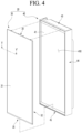
- FIG. 5 is an exploded perspective view of the panel assembly
- the front plate 31 may be formed in a rectangular plate shape, and may be formed of a material capable of transmitting light.
- the front plate 31 may be formed of a glass material such as blue glass, white glass, and deposition glass, or another material capable of transmitting light such as ABS (acrylonitrile butadiene styrene), PMMA (polymethyl methacrylate), PC (polycarbonate), or the like.
- the front plate 31 may be called a transparent plate, an out plate, or a panel.
- the front plate 31 may be formed to be transparent such that light reflected by the light guide plate 33 may be transmitted.
- transparency may be defined to an extent that light reflected from the light guide plate is transmitted and emitted to the outside.
- the front plate 31 may be configured such that the light emitted from the lighting device 36 is transmitted but the components behind the front plate 31 are not reflected. That is, in the front plate 31, the internal components of the panel assembly 30 may be prevented from being seen from the outside through the front plate 31, by the color of the front plate 31 itself when the lighting device 36 is turned off.
- the front plate 31 may be formed to have at least a color with a lightness of 0 or more, not black, when the front plate 31 is turned off. That is, in a state in which the refrigerator 1 is installed, the front surface of the refrigerator 1 may be seen in a color other than black, and the color of the front surface of the refrigerator may be changed according to the operation of the lighting device 36.
- the front plate 31 may be formed to correspond to the size of the front surface of the panel assembly 30 exposed to the outside. Specifically, the front plate 31 may be formed to have the same size as the panel assembly 30 at the upper end and the left and right-side ends except for the lower end. In addition, in a state in which the panel assembly 30 is mounted, the exposed portion of the lower bracket 35 may be shielded by the lower cap decoration 45. Accordingly, the entire front surface of the front plate 31 exposed to the outside in a state in which the panel assembly 30 is mounted may be formed by the front plate 31.
- the front plate 31 may be formed to be larger than the light guide plate 33.
- the rear surface of the front plate 31 may be coupled to the front surface of the support member 32. Therefore, in a state in which the front plate 31 is mounted on the support member 32, a separate configuration does not exist on the periphery of the front plate 31, and the front plate 31 forms the front exterior of the panel assembly 30.
- the light guide plate 33 may be positioned at a rear position spaced apart from the front plate 31, and may be configured to guide light emitted from the lighting device 36 disposed below the light guide plate 33.
- the light guide plate 33 may be formed of a transparent polymer material such as acrylic.
- the light guide plate 33 may be provided with a diffusion agent for diffusing the light incident on the light guide plate 33, or a pattern for light diffusion may be formed in the light guide plate 33. Accordingly, light can be transmitted to the front plate 31 by the light guide plate 33, and the pattern of the light guide plate 33 is set such that the entire front surface of the front plate 31 may shine with uniform brightness.
- the support member 32 may be provided between the front plate 31 and the light guide plate 33.
- the light guide plate 33 and the front plate 31 are fixedly mounted to the support member 32, and in particular, the light guide plate 33 may be spaced apart from the front plate 31 at a predetermined distance by the support member 33.
- the support member 32 may be formed such that a front surface supports the front plate 31, and both ends constrain both ends of the light guide plate 33.
- the support member 32 may be formed of a material capable of transmitting light, and may be formed by injection or extruding as a single component.
- the support member 32 may be formed of a material such as ABC, PC, or acryl, and the light reflected from the light guide plate 33 may be transmitted through the front plate 31.
- the support member 32 may be formed entirely of a transparent or translucent material, and the support member 32 itself may be formed to have a color. Accordingly, when viewed from the front of the panel assembly 30, the color, texture, or shape of the front of the panel assembly 30 may be determined by the support member 32.
- the front surface of the support member 32 through which light is transmitted may be formed to have corrosion or pattern, and may be formed such that the corrosion or pattern appears when viewed from the front of the panel assembly 30.
- the upper bracket 34 may be provided at an upper end of the panel assembly 30.
- the upper bracket 34 may form an upper surface of the panel assembly 30.
- the upper bracket 34 may be injection-formed from a plastic material, and may be formed to have a structure coupled to the support member 32 and a structure coupled to the back cover 39.
- a lower bracket 35 may be provided at a lower end of the panel assembly 30.
- the lower bracket 35 may constitute a lower surface of the panel assembly 30.
- the lower bracket 35 may be injection-formed from a plastic material, and may be formed to have a structure coupled to the support member 32 and a structure coupled to the back cover 39.
- the panel assembly 30 may include a plate supporter 47.
- the plate supporter 47 may form the exterior of the lower end of the panel assembly 30, and may allow the lower end of the panel assembly 30 to be fixed to the door body 40.
- the plate supporter 47 may include a decorative front surface and a decorative lower surface.
- the lower bracket 35 may be inserted and mounted by the decorative front surface and the decorative lower surface.
- a lower protrusion 473 extending rearward and then protruding upward is provided at the rear end of the decorative lower surface 472, and is coupled to a lower portion of the door body 40.
- the plate supporter 47 may be referred to as a lower decoration in that the plate supporter 47 is disposed at the lower end of the front plate 31.
- the back cover 39 may be coupled to the rear surface of the lower bracket 35.
- the back cover 39 may be coupled to the back cover 39 by fastening a screw.
- the rear surface of the light guide plate 33 may be supported on the front surface of the lower bracket 35. That is, when the back cover 39 is coupled, the lower bracket 35 may support the light guide plate 33 from the rear side.
- a lighting device 36 may be mounted in the lower bracket 35.
- the lighting device 36 is configured to emit light to determine the color and brightness of the front surface of the panel assembly, and to emit light toward the light guide plate 33.
- the lighting device 36 may be provided inside the lower bracket 35, and may be assembled and mounted together with the lower bracket 35 while being mounted in the lower bracket 35.
- the back cover 39 forms a rear surface of the panel assembly 30, and may be coupled to the upper bracket 34 and the lower bracket 35.
- the back cover 39 may be formed of a metal material such as stainless steel or aluminum.
- the back cover 39 may be formed to have a size corresponding to the size of the panel assembly 30, and may form the entire rear surface of the panel assembly 30.
- FIG. 6 is a cross-sectional view taken along line VI-VI' of FIG. 4 .
- FIG. 7 is a cross-sectional view showing the configuration of the front plate according to an embodiment of the present disclosure.
- FIG. 8 is a cross-sectional view showing the configuration of the front plate according to another embodiment of the present disclosure.
- FIG. 9 is a cross-sectional view showing the configuration of the front plate according to another embodiment of the present disclosure.
- the entire support member 32 may be injection-molded of a resin material, and is formed of a transparent material such that light reflected forward through the light guide plate 33 transmits through the support member 32 and directs the front plate 31.
- the support member 32 may include a plate-shaped front portion 321 and side portions 322 protruding rearward from both left and right-side ends of the front portion 321.
- the front portion 321 may be disposed between the front plate 31 and the light guide plate 33, and a front surface of the front portion 321 may support the front plate 31, and a rear surface of the front portion 321 may support the light guide plate 33.
- the side portions 322 include first surfaces 322a extending rearward from both left and right-side ends of the front portion 321 and a second surface 322b bent at the end of the first surface 322a.
- the first surfaces 322a may extend from both left and right-side ends of the front portion 321 to be perpendicular to the front portion 321 and may be formed to form side surfaces of the panel assembly 30. That is, the extended length of the first surface 322a may correspond to the side width of the panel assembly 30.
- An inner space of the panel assembly 30 may be defined by the first surfaces 322a, and a space in which at least the light guide plate 33, the upper bracket 34, and the lower bracket 35 are mounted may be formed.
- a side rib 323 may divide the space formed by the side portions 322 in a front-rear direction to form spaces into which the light guide plate 33, the upper bracket 34, and the lower bracket 35 are slidably inserted.
- the front plate 31 may implement the color of the front exterior of the refrigerator 1 by the basic color of the front plate 31 itself.
- the light reflected from the light guide plate may transmit through the front plate 31 to implement the front exterior of the refrigerator 1 in a color selected by the user.
- the basic color of the front plate 31 may be different from a set color implemented by the lighting device 36.
- the front plate 31 may implement the basic color of the front exterior of the refrigerator 1, and when the lighting device 36 is operated, the front plate 31 may be configured such that the front exterior of the refrigerator 1 has a color set by the user.
- the front plate 31 forms an overall exterior, and may include a base layer 31a formed of a material capable of transmitting light, and a colored layer 31b provided on one surface of the base layer 31a and implementing the overall color and image of the exterior panel 30.
- a pattern layer 31c forming a texture of the front exterior may be provided on the base layer 31a.
- a protective layer 31d for preventing the base layer 31a from being damaged and from scattering when the base layer 31a is damaged may be further included on the base layer 31a.
- upward direction or “downward direction” means directions based on directions shown in FIG. 6 .
- upward direction may be defined as a direction corresponding to the front surface (front) of the front plate 31.
- downstream direction may be defined as a direction corresponding to the rear surface (rear) of the front plate 31.
- the front plate 31 has a pattern layer 31c provided above the base layer 31a, and a colored layer 31b and a protective layer 31d provided below the base layer 31a to implement a basic color.
- the base layer 31a may be formed of a glass material.
- the pattern layer 31c may be formed with a pattern by the imprinting method described above, and the protective layer 31d may include an anti-shattering film to prevent the base layer 31a from scattering due to damage to the base layer 31a made of a glass material.
- the pattern layer 31c is provided above the base layer 31a, and the colored layer 31b is provided below the base layer 31a to implement a basic color.
- the base layer 31a may be formed of a light-transmitting transparent plastic material.
- a plastic material ABS, PMMA, or PC may be used.
- the pattern layer 31c may provide a texture to the front plate 31 by an imprinting method.
- a separate protective layer 31d may not be required.
- the front plate 31 may include a base layer 31a made of a glass or plastic material, and a pattern layer 31c provided above the base layer 31a, and the colored layer 31b provided below the base layer 31a.
- a deposition layer 31e may be further included above or below the base layer 31a.
- the deposition layer 31e may make it possible to more clearly realize the texture of the metal material.
- a protective layer 31d may be further provided below the colored layer 31b.
- the base layer 31a is formed of glass or a material capable of transmitting light to transmit light emitted by the lighting device 36.
- the base layer 31a When the base layer 31a is formed of glass, the base layer 31a may be formed of a blue glass, a white glass, or a glass whose surface has been subjected to deposition treatment. In order to prevent damage to the front plate 31, a tempered glass may be included.
- the "deposition treatment” may refer to a process in which, when an irregular surface is present on a glass, the irregular surface is treated to be smooth or flat, and a predetermined color is implemented on the surface of the glass.
- the base layer 31a is made of a deposited glass
- an irregular surface present in the glass may be polished, so that the exterior panel may be made more luxurious.
- the deposition process may be performed by an "evaporation" process in which a metal source is heated, dissolved, and evaporated using high-temperature heat to be deposited on a wafer, that is, the glass.
- a metal source is heated, dissolved, and evaporated using high-temperature heat to be deposited on a wafer, that is, the glass.
- various colors of the glass may be realized, making the color of the exterior panel luxurious.
- the deposition process may be performed by a sputtering process in which plasma is formed by a high voltage generated by a voltage generator and the plasma ions collide with a target to attach metal atoms to the wafer, that is, the glass surface to form a metal film.
- the base layer 31a when the base layer 31a is formed of a transparent plastic material capable of transmitting light, the base layer 31a may be formed of ABS, PMMA, or PC resin.
- a deposition layer 31e made of a film deposited with a metal may be further provided on one surface of the base layer 31a.
- the deposition layer 31e may be a film deposited with one metal selected from aluminum, chromium, zinc, copper, stainless steel, gold, silver, nickel, cobalt, iron, and tin.
- the deposition method is not particularly limited.
- the deposition layer 31e may optionally be replaced by directly performing a deposition process on the base layer 31a as described above.
- the colored layer 31b for implementing the basic color of the front plate 31 is provided on one surface of the base layer 31a. That is, the colored layer 31b is provided to implement a predetermined color, and may implement the main color of the exterior panel 30 when the lighting device 36 is turned off.
- the colored layer 31b may be formed in various colors and may be formed to have light transmittance.
- the lighting device 36 When the lighting device 36 is turned on, the light emitted from the lighting device 36 passes through the base layer 31a, so that the color of the exterior panel 30 is realized by the light sources of the lighting device 36.
- the lighting device 36 may freely select the color of the light source by the user's operation, so that the overall color of the exterior panel 30 may be be changed according to the user's selection.
- the color implemented by the colored layer 31b is seen through the transparent base layer 31a, thereby realizing the overall color of the exterior panel 30. That is, the colored layer 31b serves to set the basic color of the exterior panel 30 when the lighting device 36 is turned off.
- the base layer 31a is made of a material capable of transmitting light, other structures such as the lighting device 36 and the support member 32 disposed inside the exterior panel 30 may be seen from the front.
- the colored layer 31b implements a color or pattern behind the base layer 31a to conceal structures disposed behind the base layer 31a. Accordingly, it is possible to prevent the exterior of other structures such as the lighting device 36 from being exposed to the front of the exterior panel 30.
- a method of implementing a color in the colored layer 31b is not limited, but a deposition film or a film subjected to transfer printing is applied, or a silk screen printing method, so-called screen process may be performed to print and implement the color.
- an organic component an inorganic component, and an organic-inorganic composite component may be deposited.
- the pigment for realizing the color is not limited thereto, but an inorganic or organic pigment may be used.
- the colored layer 31b is preferably implemented by a silk screen printing method that can be used for a material made of glass because the silk screen printing method can express a variety of colors and can be performed regardless of size or material.
- the silk screen printing is so-called a screen process in which, when a fabric made of silk or chemical fiber is stretched to make a screen, a non-image portion is covered with paper or glue, and then ink is applied thereon, the ink passes through only the screen of an image portion and printing is performed.
- the silk screen printing method does not require a separate high-temperature compression process such as the gravure printing method, it is possible to easily form the colored layer 31b on the surface of the base layer 31a made of a glass material or a light-transmitting plastic material.
- the pattern layer 31c may be provided above the base layer 31a, that is, in front of the base layer 31a when the exterior panel 30 is viewed from the front.
- the pattern layer 31c may provide the exterior panel 30 with a beautiful appearance by providing texture and a sense of luxury to the exterior panel 30.
- the pattern layer 31c may include, for example, a plurality of protrusions protruding to an upper side of the base layer 31a by a predetermined height so that the user can feel the unevenness or the stone texture.
- Such texture implementation may be implemented through imprinting on a film, etching, silk screen or glass printing method.
- a uniform pattern may be formed irrespective of the length of the exterior panel 30 in the longitudinal direction, and an imprinting method capable of implementing various roughnesses may be used.
- the pattern layer 31c may be formed by performing an imprinting process on at least one surface of a film to provide various patterns such as a matte pattern or a hairline pattern to the at least one surface of the film.
- a luxurious texture may be implemented on the entire surface of the exterior panel 30 by the pattern layer 31c.
- the film forming the pattern layer 31c may be a transparent film, and may be formed of a resin material.
- the film may include at least one resin selected from the group consisting of polyethylene terephthalate (PET), polybutylene terephthalate (PBT), polypropylene (PP), polyethylene (PE), polyvinyl chloride (PVC), polymethylmethacrylate (PMMA), acrynitrilebutadienestyrene (ABS), polycarbonate (PC), and styrene-acrylonitrile copolymer (SAN).
- PET polyethylene terephthalate
- PBT polybutylene terephthalate
- PP polypropylene
- PE polyethylene
- PVC polyvinyl chloride
- PMMA polymethylmethacrylate
- ABS acrynitrilebutadienestyrene
- PC polycarbonate
- SAN styrene-acrylonitrile copolymer
- the pattern layer 31c is formed by imprinting of UV curable resin composition applied on the film with a molding roller having a pattern on the film, and UV curing is performed to implement the pattern formed on the molding roller on the film.
- the UV curable resin composition may include, but is not limited to, an acrylate-based oligomer, a monomer, a photoinitiator, and an additive.
- the acrylate-based oligomer may be, for example, one selected from urethane-based, epoxy-based, ester-based, ether-based, and silicone-based.
- a polyurethane acrylate prepared by reacting diisocyanate, polyol and methacrylate may be used, but is not necessarily limited thereto.
- a release paper coated with an adhesive may be further provided on the pattern layer 31c.
- the adhesive is preferably a hot-melt type adhesive that is adhered by heat and pressure.
- the protective layer 31d may protect the base layer 31a, and when the base layer 31a made of a glass material is damaged, prevent or alleviates scattering of the base layer 31a to reduce the risk of cuts. When the base layer 31a is made of a plastic material, the protective layer 31d may be omitted.
- This protective layer 31d may include a scattering prevention film.
- the protective layer 31d may be formed of a film in which a polymer resin is laminated, together with the scattering prevention film.
- the protective layer 31d includes a polymer resin in the scattering prevention film, the scattering prevention function and the impact resistance may be improved.
- the polymer resin is preferably formed of a material capable of transmitting light, and may include, for example, at least one of polyethylene terephthalate (PET), polyethylene naphthalate (PEN), polyether sulfone (PES), polyimide (PI), polycarbonate ( PC) and polymethyl methacrylate (PMMA) but is not limited thereto.
- PET polyethylene terephthalate
- PEN polyethylene naphthalate
- PES polyether sulfone
- PI polyimide
- PC polycarbonate
- PMMA polymethyl methacrylate
- the protective layer 31d may include an adhesive for strengthening adhesion to the base layer 31a or the colored layer 31b.
- the adhesive is not limited thereto, but may be provided by an acrylic or silicone-based adhesive.
- the protective layer 31d is provided at the rear of the base layer 31a, and is formed of a light-transmitting material such that the light emitted from the lighting device 36 can be transmitted to the base layer 31a, and the protective layer preferably has a white or white-based color.
- the protective layer 31d may be disposed behind the base layer 31a when the base layer 31a is viewed from the upper side, that is, the panel assembly 30 is viewed from the front.
- the front plate 31 will be described as a panel 31.
- FIG. 10 is a block diagram illustrating a flow of a control signal of a refrigerator.
- the controller 13 may be configured to control the lighting device 36 based on a signal received from an operation part 14 of the refrigerator and/or from a user detection sensor 151 of the refrigerator and/or of an illuminance sensor 152 of the refrigerator and/or from a microphone 18 of the refrigerator and/or from a timer 16 of the refrigerator and/or from a remote device or remote control device 2, e.g. a mobile device, PDA or mobile phone.
- FIG. 11 is a cross-sectional view showing a light emitting state of the panel assembly.
- FIG. 12 is a view showing an example of adjusting colors of home appliances to which the panel assembly is applied using the remote device.
- the exterior of the home appliance according to claim 1 is formed by the panel assembly 30, and the appearance is changed to have a color set by the user according to the operation of the lighting device 36.
- the panel assembly is expressed in various colors by light emitted from the rear side.
- the home appliance may be any one of a refrigerator 1, an air conditioner 5, a dishwasher 6, a clothes manager 7, a washing machine 8, or a cooking appliance 9, each of which may employ the same structure as that of the panel assembly 30 of the embodiment of the present invention such that the color of the front exterior thereof can be freely changed.
- the panel assembly 30 may be provided on the front surface of the door 20 that opens and closes the cabinet 10.
- the panel assembly 30 may shine in a set color by a user setting, and the color of the front exterior of the refrigerator 1 may be changed.
- the indoor unit of the air conditioner 5 may have a space, in which a heat exchange device, a fan and the like are provided, inside a case 51(or a cabinet) that forms an exterior.
- the front surface of the case 51 may be formed by a panel assembly 511.
- the panel assembly 511 may have the same structure as the panel assembly 30 of the refrigerator 1 to emit light.
- the panel assembly 511 may shine in a set color by the user setting, and the color of the front exterior of the indoor unit of the air conditioner 5 may be changed to the set color.
- the dishwasher 6 may have a space for washing of dishes inside a case 61 (or a cabinet) that forms an exterior.
- the front surface of the case 61 may be opened and closed by the door 62, and the front surface of the door 62 may be formed by the panel assembly 621.
- the panel assembly 621 may have the same structure as the panel assembly 30 of the refrigerator 1 to emit light.
- the panel assembly 511 may shine in a set color by the user setting, and the color of the front exterior of the dishwasher 6 may be changed to the set color.
- the clothes manager 7 may have a space for storing clothes inside a case 71 (or a cabinet) that forms an exterior.
- the front surface of the case 71 may be opened and closed by the door 72, and the front surface of the door 72 may be formed by the panel assembly 721.
- the panel assembly 721 may have the same structure as the panel assembly 30 of the refrigerator 1 to emit light.
- the panel assembly 721 may shine in a set color by the user setting, and the color of the front exterior of the clothes manager 7 may be changed to the set color.
- the washing machine 8 or the dryer may have a space for washing or drying inside a case 81 (or cabinet) forming the exterior.
- the front of the case 81 may be opened and closed by the door 82.
- the front of the case 81 may be formed by a panel assembly 811.
- the panel assembly 811 may have the same structure as the panel assembly 30 of the refrigerator 1 to emit light.
- the panel assembly 30 may shine in a set color by the user setting, and the color of the front exterior of the washing machine 8 or the dryer may be changed to the set color.
- the cooking appliance 9 may have a space for cooking food may be formed inside a case 91 (or a cabinet) that forms an exterior.
- the front surface of the case 91 may be opened and closed by the door 92, and the front surface of the door 92 may be formed by the panel assembly 921.
- the panel assembly 921 may have the same structure as the panel assembly 30 of the refrigerator 1 to emit light.
- the panel assembly 921 may shine in a set color by the user setting, and the color of the front exterior of the cooking appliance 9 may be changed to the set color.
- a color of the front exterior is expressed by the color of the panel 31.
- a color displayed on the panel 31 when the lighting device 36 is turned off is referred to as a first color.
- the color of the panel 31 is changed according to the color of the light emitted from the lighting device 36, and the color of the front exterior of the door 20 is expressed in the selected color.
- the color of the light emitted from the lighting device 36 is referred to as a second color
- the color of the panel that is changed when the lighting device 36 is turned on is referred to as a third color.
- the second color may be different from the third color, and the third color of the panel 31 selected by the user is implemented by a second color adjusted in consideration of the first color of the panel 31 itself. That is, the light of the second color emitted from the lighting device 36 is determined by the controller 13 in consideration of the first color of the panel 31 itself, and the panel 31 finally appears in the third color selected by the user while the light with the second color passing through the panel of the first color.
- the color of the panel 31 is determined by the selective operation of the lighting device 36.
- the lighting device 36 may be operated and set through a remote device 2 separated from the refrigerator 1.
- the refrigerator 1 may communicate with the remote device 2 through the communication device 17 connected to the controller 13, and the user operates the lighting device 36 through the remote device 2.
- the communication device 17 may communicate with the remote device 2 in various ways.
- the communication device 17 may have a structure capable of communicating in at least one communication method of wired, wireless and short-range communication (Bluetooth, Wi-Fi, Zigbee, NFC, or the like) methods.
- the remote device 2 may be various devices capable of communication, such as a dedicated terminal, a mobile phone, a tablet, a portable PC, a desktop PC, a remote control, and a Bluetooth speaker.
- the user may generally operate and set an operating state of the lighting device 36 by operating the remote device 2, such as the operating time, operating conditions, and luminous color of the light source of the lighting device 36.
- an operating state of the lighting device 36 by operating the remote device 2, such as the operating time, operating conditions, and luminous color of the light source of the lighting device 36.
- a simple operation and setting of the lighting device 36 may be possible through an application installed on the user's mobile phone or a dedicated program.
- the selection of a changed color of the panel 31 through the remote device 2 will be described as follows.
- the user may select a desired color of the panel 31 through the screen 2a of the remote device 2 such as a mobile phone or a terminal.
- the remote device When the user operates the remote device 2, the remote device first outputs a menu screen 2b to enable the user to operate a panel color change menu 2b1 through the menu screen 2b.
- the remote device 2 may output a color selection screen 2c on the menu screen 2b, and the user may select change a position of the panel 31 to be changed and the color of the panel 31 to be changed on the menu screen 2b.
- a panel position selection menu 2c1 is displayed on the color selection screen 2c to enable the user to select the panel 31 mounted on the door 20 at a desired position among the plurality of doors 20.
- the panel 31 of the door 20 selected by the user may be displayed in the panel position selection menu 2c1.
- the user may select and input color selection menus 2c2 and 2c3 displayed on the color selection screen 2c.
- all colors displayable by the panel 31 may be displayed in the form of a color picker capable of identifying and extracting a color code.
- the color selection menus 2c2 and 2c3 may be referred to as a palette because combinations and selection of various colors are possible.
- the color selection menus 2c2 and 2c3 may include a circular-shaped first selection part 2c2 and a bar-shaped second selection part 2c3. A color may be selected through the first selection part 2c2, and an intensity of the selected color may be selected through the the second selection part 2c3.
- the color selection menus 2c2 and 2c3 may include either one of the first selection part 2c2 and the second selection part 2c3.
- the user can select the color of the panel 31, that is, the third color, from among various colors through the color selection menus 2c2 and 2c3.
- the color selection menus 2c2 and 2c3 may be configured to be inputable in the form of letters, codes, and numbers.
- the user may input a color through an operation part 14 provided in the refrigerator 1 without using the remote device 2.
- the operation of the lighting device 36 may be controlled through the user's operation of the operation part 14.
- the operation part 14 may be provided at one side of the refrigerator 1, for example, at one side of the cabinet 10. It is noted that the operation part 14 may be provided on the door 20 as needed, and an input may be performed by operation such as touching or knocking on the panel 31. That is, the user may set the operation of the lighting device 36 by directly operating the operation part 14, and may turn the lighting device 36 on or off.
- the lighting device 36 may be operated by a sensor.
- the sensor may be, for example, a user detection sensor 151 that detects a user's proximity.
- the user detection sensor 151 may be implemented by various devices capable of detecting the proximity of the user to the vicinity of the refrigerator, such as an infrared sensor, an ultrasonic sensor, or a laser sensor.
- the user detection sensor 151 may be provided on one side of the cabinet or door 20, and may be disposed in various positions for detecting the proximity of the user. Further, a plurality of the sensors may be provided at different positions.
- the user detection sensor 151 detects it and transmits a signal to the controller 13 to allow the lighting device 36 to be turned on. In addition, when the user moves away from the refrigerator 1, the user detection sensor 151 detects it and transmits a signal to the controller 13 to allow the lighting device 36 to be turned off.
- the lighting device 36 may be turned off or the brightness may be gradually dimmed to prevent glare of the user.
- the lighting device 36 may be turned on again or may return to the original brightness.
- the sensor may be an illuminance sensor 152.
- the illuminance sensor 152 detects the illuminance of an indoor space and may be disposed at the same location as the user detection sensor 151.
- the lighting device 36 may be operated according to the detected illuminance of the illuminance sensor 152. For example, when the illuminance detected by the illuminance sensor 152 is less than a set illuminance and it is dark, the controller 13 may turn on the lighting device 36, and when the illuminance detected by the illuminance sensor 152 is equal to or greater than the set illuminance and it is bright, the control unit 13 may turn off the lighting device 36.
- the senor may include both the illuminance sensor 152 and the user detection sensor 151, and the controller 13 may allow the lighting device 36 to be turned on and off in cooperation with the illuminance sensor 152 and the user detection sensor 151.
- the controller 13 may be connected to a microphone 18. Therefore, the controller may allow the LED 362 to emit light in a set color according to a voice signal received from the microphone 18, and display the input state of the voice signal or the setting state of the function through the front color of the door 20.
- the controller 13 may adjust a temperature in the refrigerator to a set temperature, and operate the lighting device 36 such that the color of the front surface of the door 20 is changed to a color corresponding to the temperature.
- the lighting device 36 may be turned on and off at a time set by a timer 16. That is, the lighting device 36 may be turned on according to the time period during which the user is mainly active, and may be maintained in an off state outside the set time period. In addition, the lighting device 36 may be turned off during the day and turned on during the night, regardless of actual illuminance.
- the brightness and color of the front surface of the door 20 may be adjusted according to a user's settings regardless of the operating state of the refrigerator 1.
- the lighting device 36 may include a state in which brightness is adjusted in addition to an on state and an off state. That is, the controller 13 may adjust the output of the light emitted through the lighting device 36 to change the brightness of the panel 31. Also, the operating state of the refrigerator 1 may be indicated through the brightness of the panel 31.
- the operating state of the lighting device 36 operated by the controller 13 is described specifically.
- the light emitted by the LED 362 may be emitted toward the lower end of the light guide plate 33.
- the light emitted from the LED 362 is emitted in the second color selected by the controller 13. That is, the LED 362 is an RGB LED and emits light of the second color adjusted by the controller 13 such that the surface of the panel 31 is able to shine in the third color selected by the user.
- Light incident through the lower end of the light guide plate 33 may be diffused and reflected along the light guide plate 33, and may move along the light guide plate 33.
- the light guided by the light guide plate 33 may be reflected forward by the reflective layer 331 and be transmitted to the outside by passing through the panel 31.
- Light directed forward through the light guide plate 33 passes through the transmitting member 32 to illuminate the panel 31, and the front surface of the door 20 may shine with a set brightness or color.
- the light guide plate 33 may direct light of sufficient brightness from the entire surface forward by the LEDs 362 disposed to both ends of an LED mounting portion 361a, and thus the entire surface of the panel 31 including both ends of the panel 31 shines with uniform brightness.
- a color of the panel 31 itself is defined as a first color. Further, a color of light emitted by light sources of the lighting device is defined as a second color. In addition, a color selected by a user is defined as a third color.
- the color of the panel 31 itself is formed to have a color with a lightness of 0 or more rather than black. Therefore, in the process in which the color of the light emitted by the light source passes through the panel 31, the color of the light source and the color of the panel itself are mixed, interfered, or absorbed, so that the color of the light emitted by the light source is distorted.
- the RGB LEDs constituting the light source implement the third color selected by the user and emit light toward the panel 31, a color other than the third color is seen due to the first color of the panel 31 itself.
- the controller performs adjustment such that the entire panel is able to appear in the third color selected by the user.
- the controller receives third color information set by the user (S1).
- a user may select a desired color through a remote device or a manipulation device as the third color.
- the third color may be freely set from a palette in which combinations and selections for various color are possible.
- the controller may store the RGB values of the first color of the panel 31 in advance. Then, the controller may calculate a second color adjusted in consideration of the RGB value of the third color and the RGB value of the first color.
- the second color information may be calculated by, for example, reflecting an adjustment value calculated in consideration of the first color to the RGB value of the third color using a relational expression derived through an experiment.
- the controller controls the light sources of the lighting device to emit light with the calculated second color (S3).
- the light sources emit light in the second color
- the light passes through the panel 31 of the first color, so that the front surface of the panel 31 shines in the third color.
- the screen may correspond to the aforementioned panel 31.
- a home appliance may include a cabinet having a predetermined space; a door that opens and closes the space; a screen installed on the front surface of the door to change from a first color recognized by the user to a third color selected by the user at the front of the door and perform display; an operation part that enables the user to select third color; and RGB LEDs that emit light with a second color toward the screen, the second color being generated by mixing light of the light emitting elements.
- the controller may perform control such that the third color is displayed on the screen, the third color being generated by mixing the first color when the RGB LEDs are turned off and the second color when the RGB LEDs are turned on.
- a home appliance includes a cabinet having a first space and a second space; a first door for opening and closing the first space; a second door for opening and closing a second space; a first screen installed on the front surface of the first door to perform change to a third color selected by the user and display the third color; a second screen installed on the front surface of the second door to perform change to a fourth color selected by the user and display the fourth color; a remote communication terminal for enabling the user to select the first door and then set the third color or select the second door and then set the fourth color; a first RGB LED for emitting light of a color generated by mixing light from light emitting elements toward the first screen according to selection of the third color through the remote communication terminal; and a second RGB LED for emitting light of a color generated by mixing light from light emitting elements toward the second screen according to selection of the fourth color through the remote communication terminal.
- the front surface of the door 20 does not shine, and the original color of the panel assembly 30, that is, the first color is visible.
- the panel assembly 30 has a structure that is separable from the door body 40, so that a user can select an initial color of the panel 31 by mounting the panel assembly 30 of a desired color. It is noted that, if necessary, the user may change the color of the panel 31 when the lighting device 36 is turned off, by exchanging the panel assembly 30 itself.
- the color of the front surface of the door 20 is seen as the color of the panel 31, and the texture and pattern formed on the panel 31 may be seen.
- the panel 31 may be formed to have a color having a lightness greater than 0, other than black.
- the surface of the front surface of the door 20 is seen in the first color that is the color of the panel 31, and in this case, the components inside the panel assembly 30 cannot be seen from the outside by the color of the panel 31 without seeing through the panel 31.
- the lighting device 36 may be turned on, and when the lighting device 36 is turned on, the front surface of the door 20 shines in a color selected by the user.
- the controller 13 performs control such that the front surface of the door 20 shines in a third color different from the first color, and the lighting device 36 allows the LED 362s to emit light of the second color under the control of the controller 13.
- the third color is selected by the user, and the color of the panel 31 may be selected by the operation of the remote device 2 or the operation of the operation part 14.
- the LED 362 emits light in the second color
- the light reflected by the light guide plate 33 passes through the front surface of the panel 31, and the front surface of the door 20, that is, the panel 31 is seen in the third color.
- the controller 13 instructs the lighting device 36 to change the color of the light emitted from the lighting device 36 while the front exterior of the refrigerator 1 shines in the third color
- the panel 31 may shine in a different color reset by the controller 13.
- the controller 13 may instruct the panel 31 to shine in a fourth color different from the third color, and the lighting device 36 may allow the LED 362 to emit light of a different color under the control of the controller 13.
- the LED 362 emits light in the different color
- the light reflected by the light guide plate 33 passes through the panel 31, and the front surface of the door 20, that is, the panel 31 may be seen in the fourth color.
- the panel 31 constituting some doors 20 of the plurality of doors 20 forming the front exterior of the refrigerator 1 emits light or the panels 31 constituting the plurality of doors 20 may independent emit light to form the front exterior of the refrigerator 1 in set colors.
- the refrigerator 1 may be operated such that the panel 31 of some doors 20 among the plurality of doors 20 shines or shines in a specific color. That is, not all of the lighting devices 36 provided in the doors 20 are operated, but may be configured such that only some doors 201a of all doors 20 shine.
- any one door 201a of the refrigerating chamber doors 201 may shine. That is, the left refrigerating chamber door 201a among the left refrigerating chamber door 201a and the right refrigerating chamber door 201b may shine.
- any one of the freezing chamber doors 202 may shine.
- the left refrigerating chamber door 201a and the right refrigerating chamber door 201b may shine in different colors.
- colors of at least two or more of the doors 20 may be sequentially changed, and at least two or more of the doors 20 may be sequentially turned on and off.
- the refrigerating chamber door 20 or the freezing chamber door 20 among the doors may be controlled to shine in different colors.
- the controller 13 may control the lighting device 36 such that the panels of the pair of refrigerating chamber doors 201 are seen in one color.
- the controller 13 may control the lighting device 36 such that the pair of refrigerating chamber doors 201 are seen in different colors.
- the refrigerating chamber door 201 and the freezing chamber door 202 may be distinguished by colors, and the colors of the refrigerating chamber door 201 and the freezing chamber door 202 may be changed according to a change in temperature of the refrigerator.
- the user can intuitively grasp the operating state of each storage space as well as distinguish between the refrigerating chamber and the freezing chamber through colors of the front surface of the door 20.
- a storage space may be partitioned on left and right sides, and the doors may include a refrigerating chamber door and a freezing chamber door on the left and right sides.
- the another embodiment of the present disclosure has the same structure as the above-described embodiment except for the arrangement of the storage spaces and the doors, and the same reference numerals are used for the same components, and detailed descriptions thereof will be omitted.
Landscapes
- Engineering & Computer Science (AREA)
- Physics & Mathematics (AREA)
- General Engineering & Computer Science (AREA)
- Mechanical Engineering (AREA)
- Chemical & Material Sciences (AREA)
- Combustion & Propulsion (AREA)
- Thermal Sciences (AREA)
- General Physics & Mathematics (AREA)
- Optics & Photonics (AREA)
- Microelectronics & Electronic Packaging (AREA)
- Civil Engineering (AREA)
- Structural Engineering (AREA)
- Spectroscopy & Molecular Physics (AREA)
- Textile Engineering (AREA)
- Devices That Are Associated With Refrigeration Equipment (AREA)
- Refrigerator Housings (AREA)
- Led Devices (AREA)
- Control Of Throttle Valves Provided In The Intake System Or In The Exhaust System (AREA)
- Gyroscopes (AREA)
- Arrangement Of Elements, Cooling, Sealing, Or The Like Of Lighting Devices (AREA)
Claims (13)
- Appareil ménager comportant :une armoire (10) ayant un espace formé dans celle-ci ;une porte (20) configurée pour ouvrir et fermer l'armoire (10) et incluant un ensemble de panneau (30), dans lequel l'ensemble de panneau (30) inclut un dispositif d'éclairage (36) configuré pour émettre de la lumière et une plaque avant (31) formant un extérieur de la porte (20), la plaque avant (31) étant configurée pour transmettre la lumière provenant du dispositif d'éclairage (36) ; etune commande (13) configurée pour commander le dispositif d'éclairage (36),dans lequel la plaque avant (31) inclut une couche de base (31a) et une couche colorée (31b) formée sur la couche de base (31a), la couche colorée (31b) ayant une première couleur,dans lequel la plaque avant (31) a la première couleur lorsque le dispositif d'éclairage (36) est éteint, et une troisième couleur sélectionnable par un utilisateur parmi une pluralité de différentes couleurs et différente de la première couleur lorsque le dispositif d'éclairage (36) est allumé, etcaractérisé en ce quela commande (36) est configurée pour commander au dispositif d'éclairage (36) d'émettre de la lumière dans une deuxième couleur ajustée en fonction de la première couleur de telle sorte que la plaque avant (31) a la troisième couleur.
- Appareil ménager selon l'une quelconque des revendications précédentes, dans lequel le dispositif d'éclairage peut inclure une pluralité de LED RGB.
- Appareil ménager selon l'une quelconque des revendications précédentes, dans lequel la couche de base (31a) est constituée d'au moins un élément parmi un matériau transparent, du verre, une matière plastique transparente, de l'ABS (acrylonitrile butadiène styrène), du PMMA (polyméthacrylate de méthyle) ou une résine de PC (polycarbonate).
- Appareil ménager selon l'une quelconque des revendications précédentes, dans lequel la couche colorée (31b) a une luminosité supérieure à 0.
- Appareil ménager selon l'une quelconque des revendications précédentes, dans lequel la couche colorée (31b) est formée par un procédé d'impression par sérigraphie sur la couche de base (31a).
- Appareil ménager selon l'une quelconque des revendications précédentes, dans lequel la couche colorée (31b) est formée sur une surface arrière de la couche de base (31a).
- Appareil ménager selon l'une quelconque des revendications précédentes, dans lequel la plaque avant (31) inclut en outre une couche de motif (31c) formée sur ou dans une surface avant de la couche de base (31a) pour définir une texture de la porte (20).
- Appareil ménager selon la revendication 7, dans lequel la couche de motif (31c) inclut un film transparent formé d'un matériau en résine.
- Appareil ménager selon la revendication 7 ou 8, dans lequel la couche de motif (31c) inclut une empreinte de composition de résine durcie aux UV.
- Appareil ménager selon l'une quelconque des revendications précédentes, dans lequel la plaque avant (31) inclut en outre une couche protectrice (31d) formée sur une surface de la couche colorée (31b) opposée à la couche de base (31a).
- Appareil ménager selon la revendication 10, dans lequel la couche protectrice (31d) inclut un film anti-diffusion.
- Appareil ménager selon l'une quelconque des revendications précédentes, incluant en outre une couche de dépôt (31e) entre la couche de base (31a) et la couche colorée (31b).
- Appareil ménager selon l'une quelconque des revendications précédentes, dans lequel l'appareil ménager est un appareil quelconque parmi un réfrigérateur, un lave-linge, un appareil de gestion de vêtements, une machine à laver, un lave-vaisselle et un appareil de cuisson.
Applications Claiming Priority (1)
| Application Number | Priority Date | Filing Date | Title |
|---|---|---|---|
| KR1020210157921A KR20230071576A (ko) | 2021-11-16 | 2021-11-16 | 가전기기 |
Publications (3)
| Publication Number | Publication Date |
|---|---|
| EP4179947A1 EP4179947A1 (fr) | 2023-05-17 |
| EP4179947B1 true EP4179947B1 (fr) | 2025-07-02 |
| EP4179947C0 EP4179947C0 (fr) | 2025-07-02 |
Family
ID=84358902
Family Applications (1)
| Application Number | Title | Priority Date | Filing Date |
|---|---|---|---|
| EP22207771.1A Active EP4179947B1 (fr) | 2021-11-16 | 2022-11-16 | Appareil ménager |
Country Status (5)
| Country | Link |
|---|---|
| US (2) | US12019263B2 (fr) |
| EP (1) | EP4179947B1 (fr) |
| KR (1) | KR20230071576A (fr) |
| CN (1) | CN116136353A (fr) |
| AU (1) | AU2022271422B2 (fr) |
Families Citing this family (4)
| Publication number | Priority date | Publication date | Assignee | Title |
|---|---|---|---|---|
| KR20210153887A (ko) * | 2020-06-11 | 2021-12-20 | 삼성전자주식회사 | 식기세척기 및 가전기기 |
| KR20230071576A (ko) * | 2021-11-16 | 2023-05-23 | 엘지전자 주식회사 | 가전기기 |
| KR20250130145A (ko) * | 2024-02-23 | 2025-09-01 | 엘지전자 주식회사 | 가전기기용 도어 및 이를 포함하는 가전기기 |
| US20250369606A1 (en) * | 2024-05-29 | 2025-12-04 | Anthony Klingshirn | Color Changing Cabinets Device |
Citations (2)
| Publication number | Priority date | Publication date | Assignee | Title |
|---|---|---|---|---|
| US20130194167A1 (en) * | 2012-01-31 | 2013-08-01 | Samsung Electronics Co., Ltd. | Display apparatus, display panel, and display method |
| US10561256B2 (en) * | 2017-06-30 | 2020-02-18 | Sam Allen | Locker with illuminated indicia |
Family Cites Families (25)
| Publication number | Priority date | Publication date | Assignee | Title |
|---|---|---|---|---|
| US6840773B2 (en) * | 2002-03-07 | 2005-01-11 | Jan Anderson | Decorative magnetic sheet and method for decorating an appliance |
| US7246926B2 (en) * | 2004-05-11 | 2007-07-24 | Harwood Ronald P | Color changing light fixture |
| DE102005021607A1 (de) | 2005-05-10 | 2006-11-23 | BSH Bosch und Siemens Hausgeräte GmbH | Tür für ein Haushaltsgerät |
| KR101576672B1 (ko) * | 2008-02-21 | 2015-12-10 | 엘지전자 주식회사 | 냉장고 및 냉장고 도어 |
| CN101551188A (zh) * | 2008-03-31 | 2009-10-07 | 无锡松下冷机有限公司 | 电冰箱及其控制方法 |
| CN101650109A (zh) * | 2008-08-14 | 2010-02-17 | 博西华家用电器有限公司 | 家用电器以及用于家用电器的玻璃面板 |
| US8567976B2 (en) * | 2009-12-08 | 2013-10-29 | Magna International Inc. | Appliance doors having integrated lighting and controls |
| CA2760815A1 (fr) * | 2010-02-01 | 2011-08-04 | Lg Electronics Inc. | Refrigerateur et son procede de commande |
| TR201010199A2 (tr) | 2010-12-08 | 2012-06-21 | Bsh Ev Aletleri̇ San. Ve Ti̇c. A.Ş. | Işiklandırılmış kapıya sahip bir soğutucu cihaz |
| US20140078407A1 (en) * | 2012-03-06 | 2014-03-20 | Planar Systems, Inc. | Transparent electronic image display apparatus for refrigerated merchandisers and the like |
| EP2870504A1 (fr) * | 2012-07-09 | 2015-05-13 | Red Bull GmbH | Dispositif d'affichage transparent |
| JP6373653B2 (ja) * | 2013-06-25 | 2018-08-15 | 東芝ライフスタイル株式会社 | 冷蔵庫 |
| US9702619B2 (en) * | 2013-07-31 | 2017-07-11 | Whirlpool Corporation | Controlled, dynamic lighting of interior of appliance |
| US9857072B2 (en) * | 2014-03-12 | 2018-01-02 | American Heating Technologies Inc. | Apparatuses, methods, and systems for illuminating panels used as cabinet doors and drawer panels |
| KR102058456B1 (ko) * | 2015-08-31 | 2019-12-23 | 삼성전자주식회사 | 디스플레이 장치 및 이를 포함하는 가전기기 |
| KR102399724B1 (ko) * | 2015-09-24 | 2022-05-20 | 삼성전자주식회사 | 디스플레이 장치, 그를 가지는 도어 및 냉장고 |
| KR101829352B1 (ko) * | 2016-01-05 | 2018-03-29 | 엘지전자 주식회사 | 냉장고 |
| KR101810760B1 (ko) * | 2016-01-05 | 2017-12-19 | 엘지전자 주식회사 | 냉장고 및 냉장고의 제어 방법 |
| CN106123457B (zh) * | 2016-06-23 | 2018-09-04 | 青岛海尔股份有限公司 | 冰箱 |
| KR101815383B1 (ko) * | 2016-06-30 | 2018-01-30 | 엘지전자 주식회사 | 냉장고 및 냉장고 디스플레이 어셈블리 |
| US10415876B2 (en) * | 2016-07-11 | 2019-09-17 | Haier Us Appliance Solutions, Inc. | Handle lighting assembly for an appliance |
| EP4085799B1 (fr) * | 2017-03-24 | 2025-01-29 | LG Electronics Inc. | Réfrigérateur |
| US10420186B2 (en) * | 2017-05-31 | 2019-09-17 | Nbcuniversal Media, Llc | Color tunable light with zone control |
| TWI813920B (zh) * | 2019-12-06 | 2023-09-01 | 美商伊路米納有限公司 | 電子裝置及其封閉件 |
| KR20230071576A (ko) * | 2021-11-16 | 2023-05-23 | 엘지전자 주식회사 | 가전기기 |
-
2021
- 2021-11-16 KR KR1020210157921A patent/KR20230071576A/ko active Pending
-
2022
- 2022-11-15 CN CN202211431565.6A patent/CN116136353A/zh active Pending
- 2022-11-16 EP EP22207771.1A patent/EP4179947B1/fr active Active
- 2022-11-16 US US17/988,384 patent/US12019263B2/en active Active
- 2022-11-16 AU AU2022271422A patent/AU2022271422B2/en active Active
-
2024
- 2024-05-14 US US18/663,373 patent/US20240295683A1/en active Pending
Patent Citations (2)
| Publication number | Priority date | Publication date | Assignee | Title |
|---|---|---|---|---|
| US20130194167A1 (en) * | 2012-01-31 | 2013-08-01 | Samsung Electronics Co., Ltd. | Display apparatus, display panel, and display method |
| US10561256B2 (en) * | 2017-06-30 | 2020-02-18 | Sam Allen | Locker with illuminated indicia |
Also Published As
| Publication number | Publication date |
|---|---|
| CN116136353A (zh) | 2023-05-19 |
| US12019263B2 (en) | 2024-06-25 |
| KR20230071576A (ko) | 2023-05-23 |
| AU2022271422B2 (en) | 2024-05-02 |
| AU2022271422A1 (en) | 2023-06-01 |
| EP4179947C0 (fr) | 2025-07-02 |
| US20230152504A1 (en) | 2023-05-18 |
| EP4179947A1 (fr) | 2023-05-17 |
| US20240295683A1 (en) | 2024-09-05 |
Similar Documents
| Publication | Publication Date | Title |
|---|---|---|
| EP4179947B1 (fr) | Appareil ménager | |
| KR20250031181A (ko) | 가전기기 | |
| EP4119873B1 (fr) | Appareil ménager | |
| EP2245401A1 (fr) | Réfrigérateur et porte de réfrigérateur | |
| US20260016220A1 (en) | Refrigerator | |
| EP4119878A1 (fr) | Ensemble panneau pour un appareil ménager et appareil ménager le comprenant | |
| EP4174423A1 (fr) | Appareil ménager et réfrigérateur | |
| US12215917B2 (en) | Refrigerator and home appliance | |
| US20250189208A1 (en) | Home appliance | |
| KR20230011153A (ko) | 냉장고 및 가전기기 | |
| KR20230011150A (ko) | 냉장고 및 가전기기 | |
| KR20230011154A (ko) | 냉장고 및 가전기기 | |
| US12215850B2 (en) | Home appliance | |
| US20250035367A1 (en) | Home appliance | |
| KR20230011147A (ko) | 냉장고 및 가전기기 | |
| KR20230071625A (ko) | 가전 기기 | |
| KR20230011148A (ko) | 냉장고 및 가전기기 | |
| CN115615096A (zh) | 家用电器 |
Legal Events
| Date | Code | Title | Description |
|---|---|---|---|
| PUAI | Public reference made under article 153(3) epc to a published international application that has entered the european phase |
Free format text: ORIGINAL CODE: 0009012 |
|
| STAA | Information on the status of an ep patent application or granted ep patent |
Free format text: STATUS: REQUEST FOR EXAMINATION WAS MADE |
|
| 17P | Request for examination filed |
Effective date: 20221116 |
|
| AK | Designated contracting states |
Kind code of ref document: A1 Designated state(s): AL AT BE BG CH CY CZ DE DK EE ES FI FR GB GR HR HU IE IS IT LI LT LU LV MC ME MK MT NL NO PL PT RO RS SE SI SK SM TR |
|
| RBV | Designated contracting states (corrected) |
Designated state(s): AL AT BE BG CH CY CZ DE DK EE ES FI FR GB GR HR HU IE IS IT LI LT LU LV MC ME MK MT NL NO PL PT RO RS SE SI SK SM TR |
|
| REG | Reference to a national code |
Ref country code: DE Ref legal event code: R079 Free format text: PREVIOUS MAIN CLASS: A47L0015420000 Ref country code: DE Ref legal event code: R079 Ref document number: 602022016802 Country of ref document: DE Free format text: PREVIOUS MAIN CLASS: A47L0015420000 Ipc: F25D0023020000 |
|
| GRAP | Despatch of communication of intention to grant a patent |
Free format text: ORIGINAL CODE: EPIDOSNIGR1 |
|
| STAA | Information on the status of an ep patent application or granted ep patent |
Free format text: STATUS: GRANT OF PATENT IS INTENDED |
|
| RIC1 | Information provided on ipc code assigned before grant |
Ipc: F25D 27/00 20060101ALI20250207BHEP Ipc: F25D 23/02 20060101AFI20250207BHEP |
|
| INTG | Intention to grant announced |
Effective date: 20250219 |
|
| GRAS | Grant fee paid |
Free format text: ORIGINAL CODE: EPIDOSNIGR3 |
|
| GRAA | (expected) grant |
Free format text: ORIGINAL CODE: 0009210 |
|
| STAA | Information on the status of an ep patent application or granted ep patent |
Free format text: STATUS: THE PATENT HAS BEEN GRANTED |
|
| AK | Designated contracting states |
Kind code of ref document: B1 Designated state(s): AL AT BE BG CH CY CZ DE DK EE ES FI FR GB GR HR HU IE IS IT LI LT LU LV MC ME MK MT NL NO PL PT RO RS SE SI SK SM TR |
|
| REG | Reference to a national code |
Ref country code: GB Ref legal event code: FG4D |
|
| REG | Reference to a national code |
Ref country code: CH Ref legal event code: EP |
|
| REG | Reference to a national code |
Ref country code: DE Ref legal event code: R096 Ref document number: 602022016802 Country of ref document: DE |
|
| REG | Reference to a national code |
Ref country code: IE Ref legal event code: FG4D |
|
| U01 | Request for unitary effect filed |
Effective date: 20250717 |
|
| U07 | Unitary effect registered |
Designated state(s): AT BE BG DE DK EE FI FR IT LT LU LV MT NL PT RO SE SI Effective date: 20250724 |
|
| U20 | Renewal fee for the european patent with unitary effect paid |
Year of fee payment: 4 Effective date: 20251124 |
|
| PG25 | Lapsed in a contracting state [announced via postgrant information from national office to epo] |
Ref country code: IS Free format text: LAPSE BECAUSE OF FAILURE TO SUBMIT A TRANSLATION OF THE DESCRIPTION OR TO PAY THE FEE WITHIN THE PRESCRIBED TIME-LIMIT Effective date: 20251102 |
|
| PG25 | Lapsed in a contracting state [announced via postgrant information from national office to epo] |
Ref country code: NO Free format text: LAPSE BECAUSE OF FAILURE TO SUBMIT A TRANSLATION OF THE DESCRIPTION OR TO PAY THE FEE WITHIN THE PRESCRIBED TIME-LIMIT Effective date: 20251002 |
|
| PG25 | Lapsed in a contracting state [announced via postgrant information from national office to epo] |
Ref country code: HR Free format text: LAPSE BECAUSE OF FAILURE TO SUBMIT A TRANSLATION OF THE DESCRIPTION OR TO PAY THE FEE WITHIN THE PRESCRIBED TIME-LIMIT Effective date: 20250702 |
|
| PG25 | Lapsed in a contracting state [announced via postgrant information from national office to epo] |
Ref country code: GR Free format text: LAPSE BECAUSE OF FAILURE TO SUBMIT A TRANSLATION OF THE DESCRIPTION OR TO PAY THE FEE WITHIN THE PRESCRIBED TIME-LIMIT Effective date: 20251003 |
|
| PG25 | Lapsed in a contracting state [announced via postgrant information from national office to epo] |
Ref country code: CZ Free format text: LAPSE BECAUSE OF FAILURE TO SUBMIT A TRANSLATION OF THE DESCRIPTION OR TO PAY THE FEE WITHIN THE PRESCRIBED TIME-LIMIT Effective date: 20250702 |
|
| PG25 | Lapsed in a contracting state [announced via postgrant information from national office to epo] |
Ref country code: PL Free format text: LAPSE BECAUSE OF FAILURE TO SUBMIT A TRANSLATION OF THE DESCRIPTION OR TO PAY THE FEE WITHIN THE PRESCRIBED TIME-LIMIT Effective date: 20250702 |
|
| PG25 | Lapsed in a contracting state [announced via postgrant information from national office to epo] |
Ref country code: RS Free format text: LAPSE BECAUSE OF FAILURE TO SUBMIT A TRANSLATION OF THE DESCRIPTION OR TO PAY THE FEE WITHIN THE PRESCRIBED TIME-LIMIT Effective date: 20251002 |
|
| PG25 | Lapsed in a contracting state [announced via postgrant information from national office to epo] |
Ref country code: ES Free format text: LAPSE BECAUSE OF FAILURE TO SUBMIT A TRANSLATION OF THE DESCRIPTION OR TO PAY THE FEE WITHIN THE PRESCRIBED TIME-LIMIT Effective date: 20250702 |
|
| PG25 | Lapsed in a contracting state [announced via postgrant information from national office to epo] |
Ref country code: SM Free format text: LAPSE BECAUSE OF FAILURE TO SUBMIT A TRANSLATION OF THE DESCRIPTION OR TO PAY THE FEE WITHIN THE PRESCRIBED TIME-LIMIT Effective date: 20250702 |